

Overvoltage Simulation Analysis and Suppression of Breaking in a 35 kV Shunt Reactor

Abstract
1. Introduction
2. Analysis of Phase-to-Phase Overvoltage Caused by Shunt Reactor Breaking
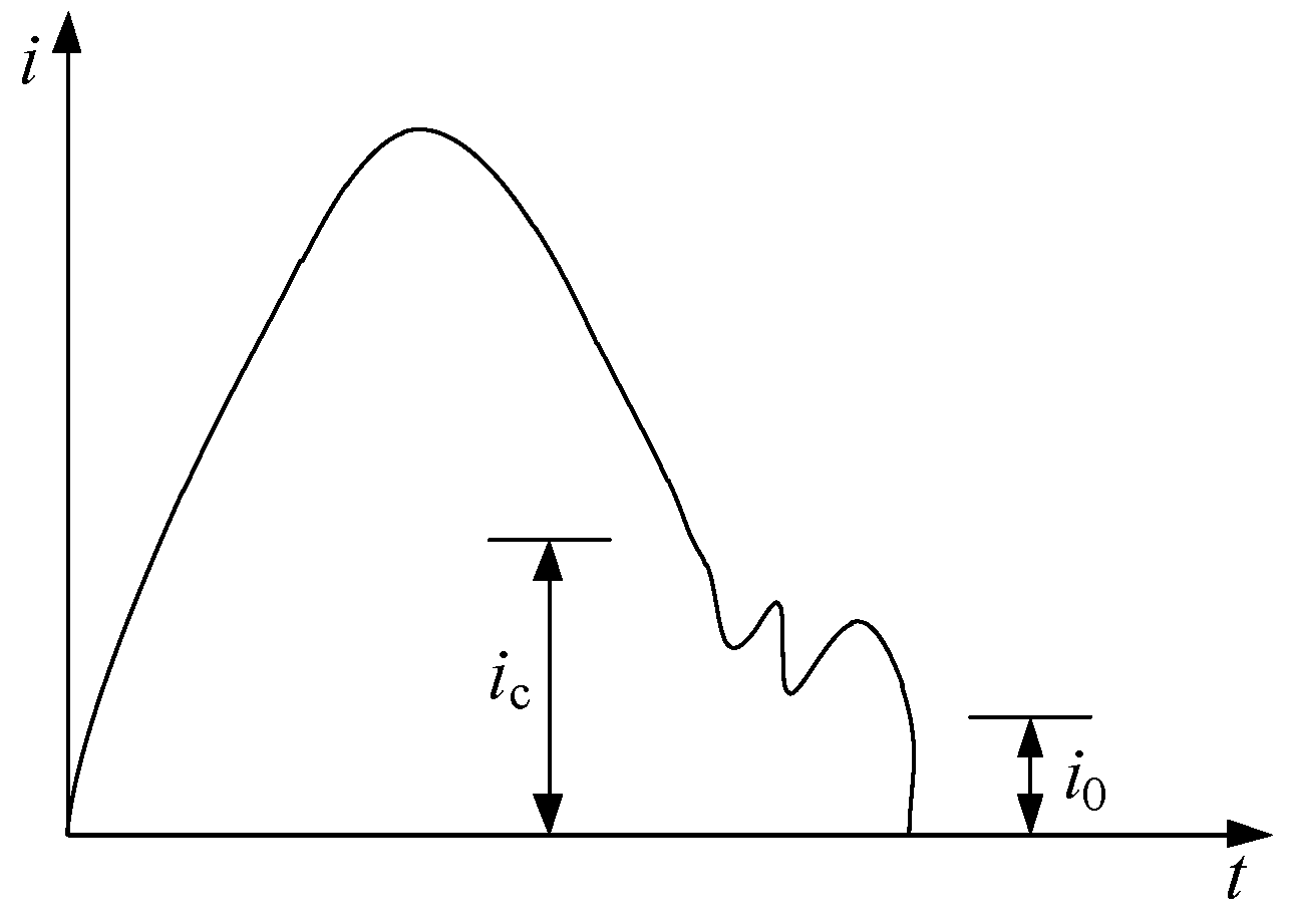
2.1. Cut-Off Current Overvoltage
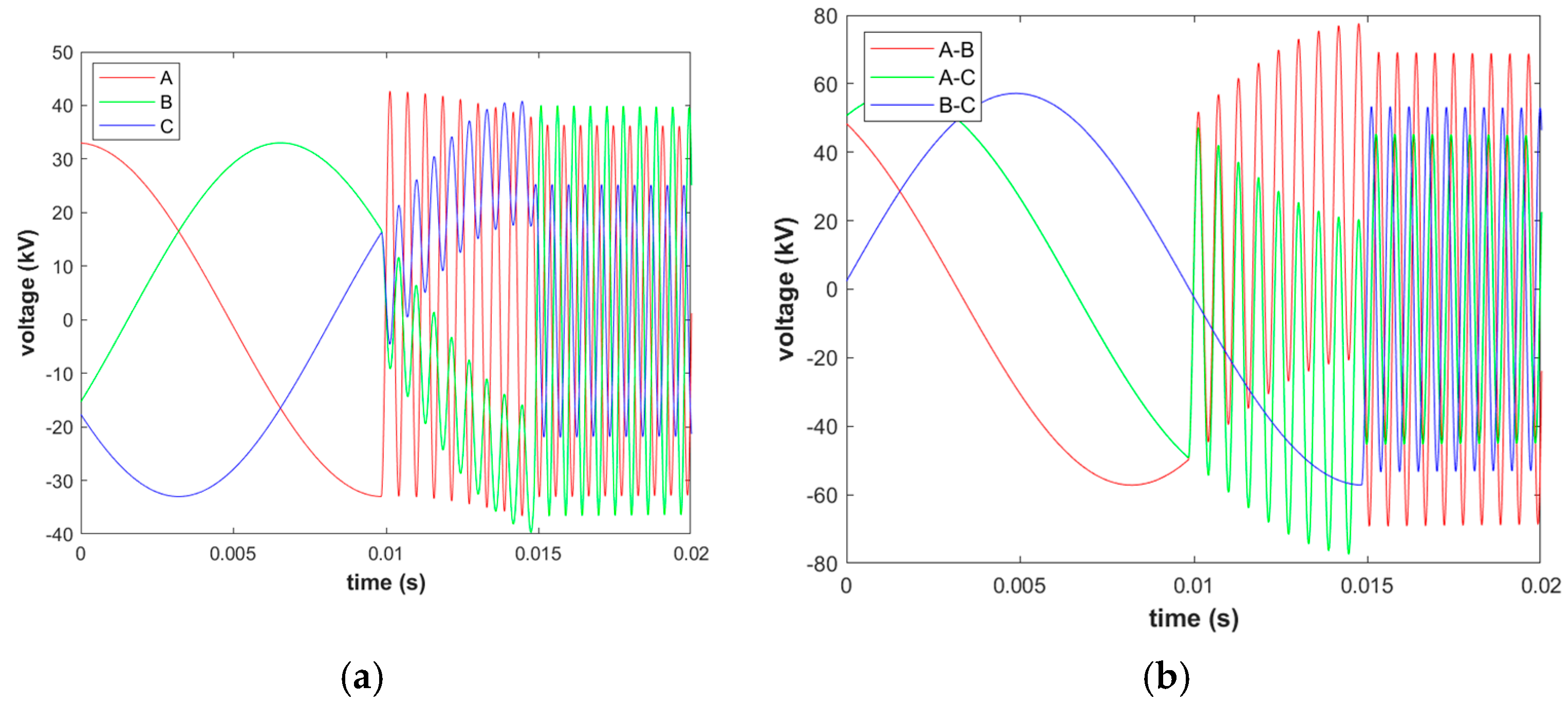
2.2. Restrike Overvoltage
- (1)
- There is no obvious change in the overvoltage when the first open phase is reignited, and it can be judged that the overvoltage caused by the reignition is not strong.
- (2)
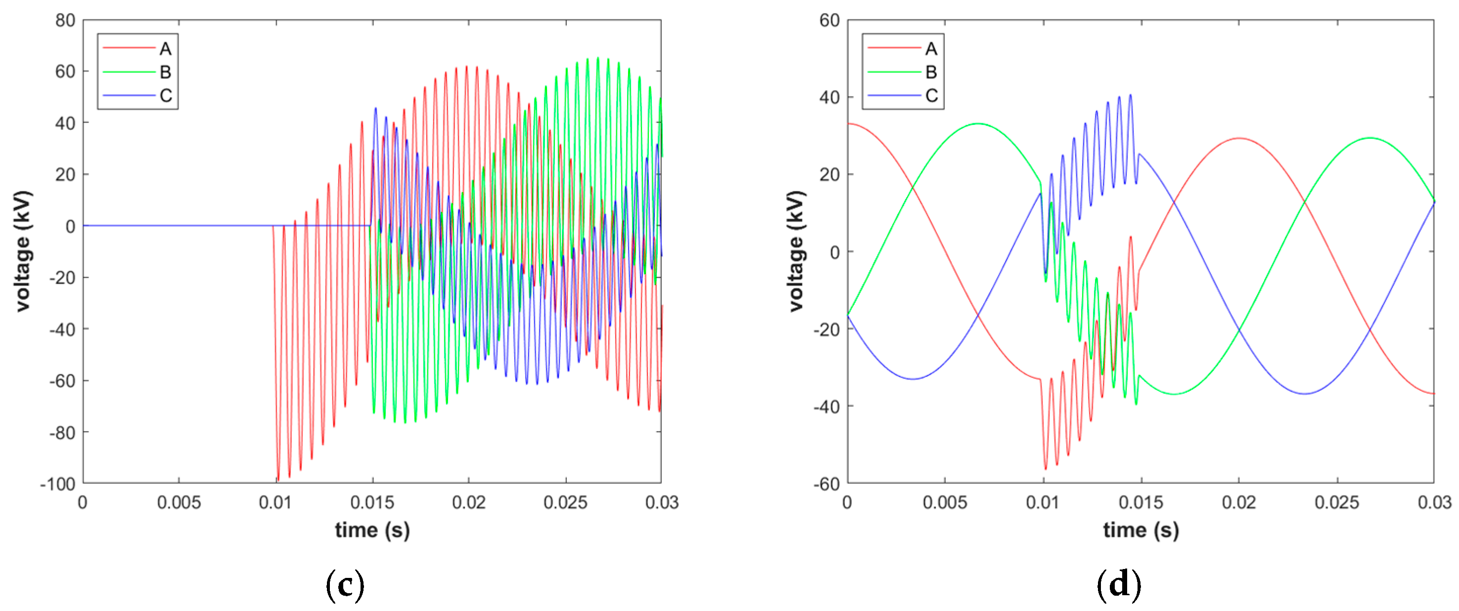
- With the increase in the number of reignitions in the first open phase, the reignition current increases continuously and the anti-side-to-ground overvoltage shows an upward trend. The repeated reignition is equivalent to continuously replenishing the energy, bringing about a step-up in the voltage.
- (3)
- With the increase in the number of reignitions in the first open phase, the phase-to-phase overvoltage between the first open phase A and the other two phases B and C on the anti-side will increase. However, in the simulation calculation, the overvoltage of the latter two phases is small: the B-C phase-to-phase overvoltage multiple is only 1.73 p.u., and with the increase in the number of repeated reignitions, it does not change much.
- (4)
- The overvoltage of the bus side relative to the ground increases with the increase in the number of reignitions in the first phase.
2.3. Equivalent Cut-Off Overvoltage
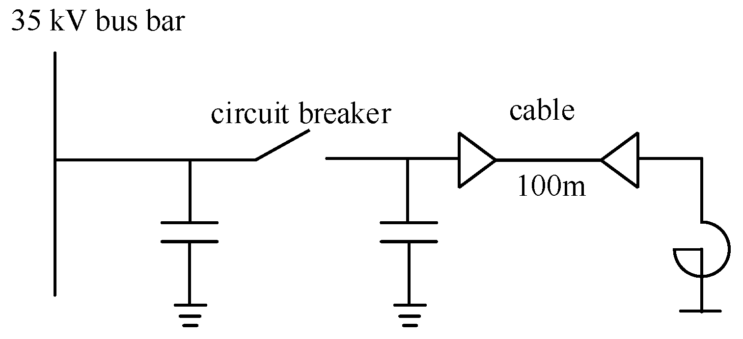
3. Simulation of a 35 kV Shunt Reactor Breaking Overvoltage
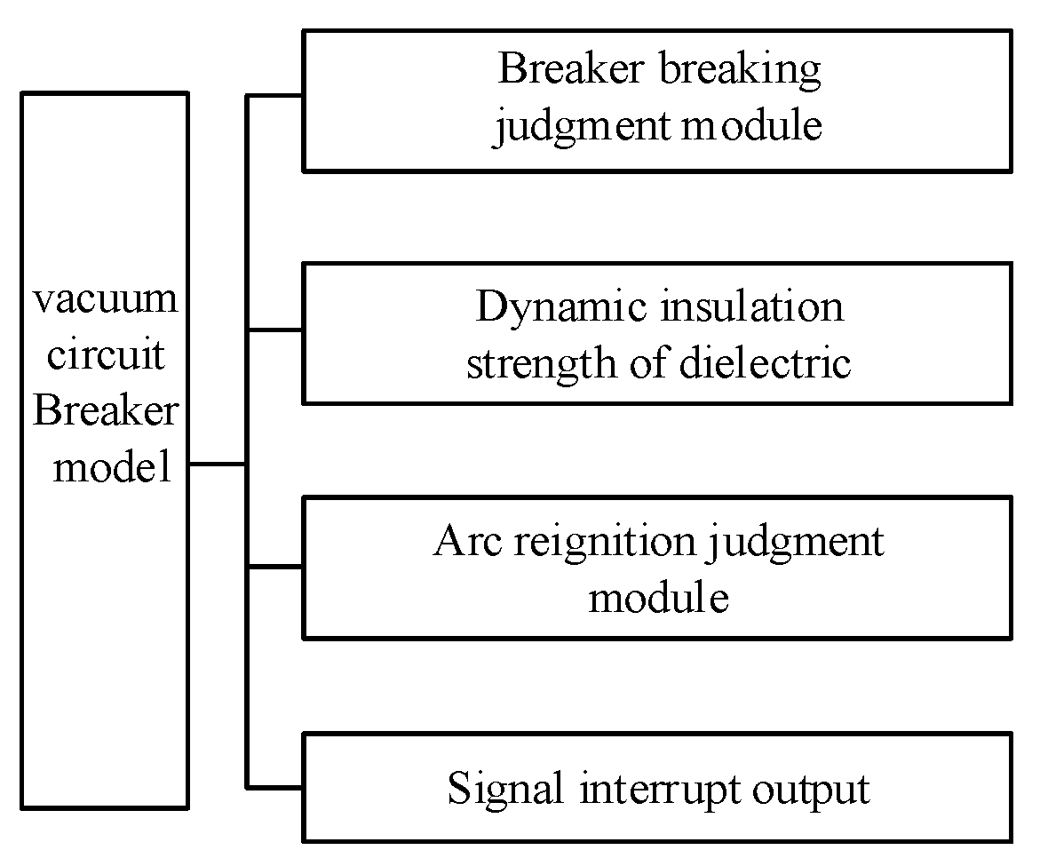
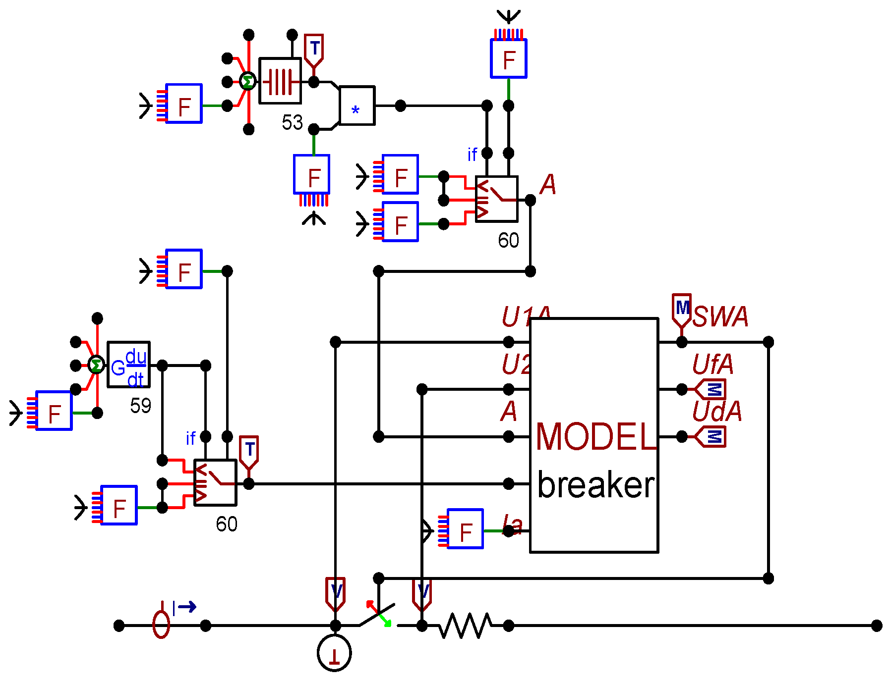
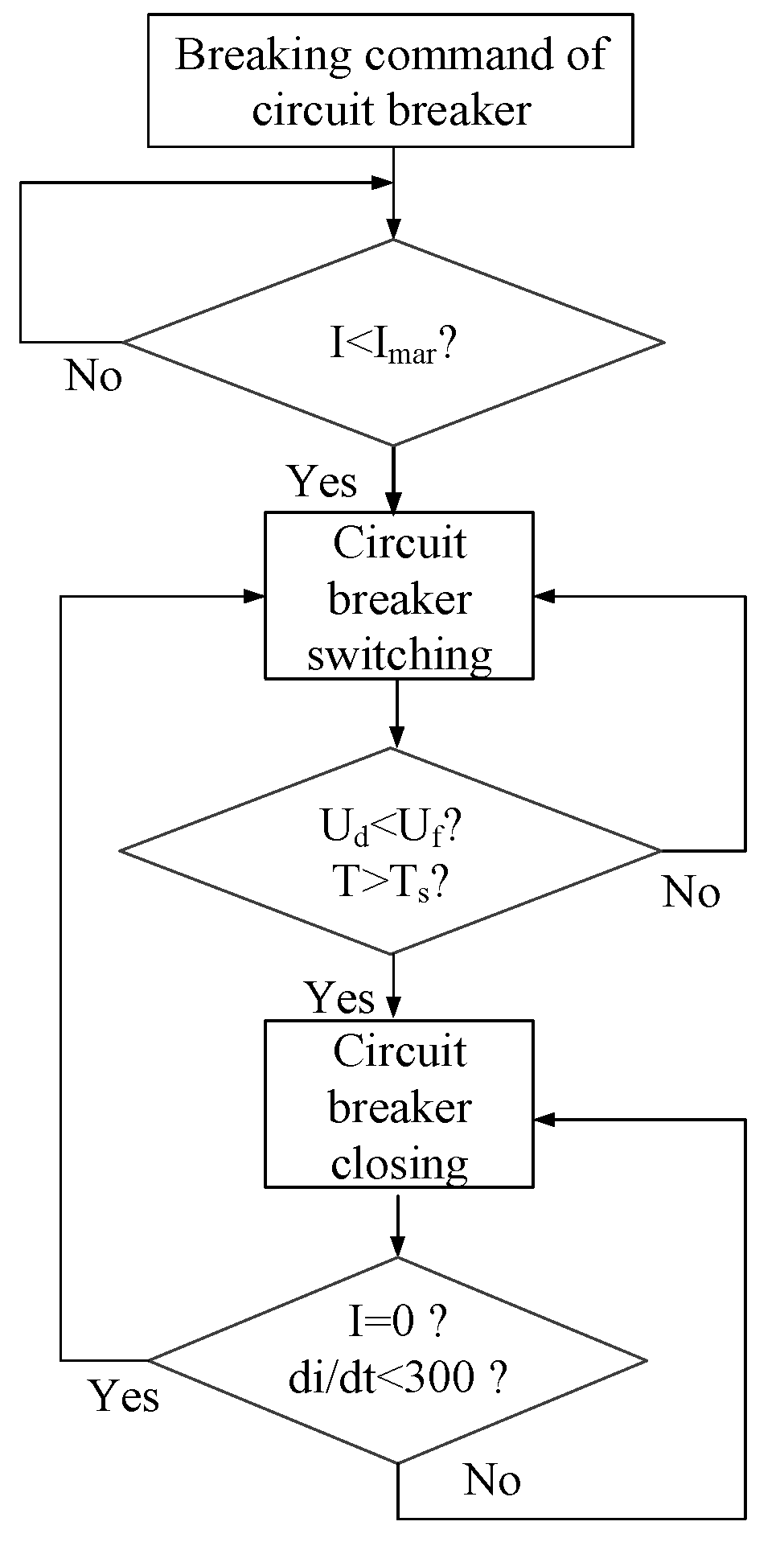
3.1. Modeling of Vacuum Circuit Breaker
- (1)
- Circuit breaker breaking module
- (2)
- Dielectric insulation strength and reignition judgment process
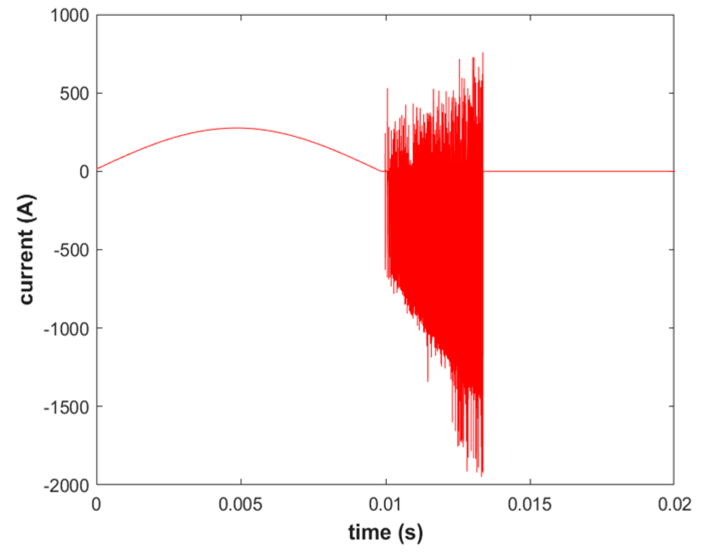
3.2. Simulation of Equivalent Interception
3.3. Continuous Reburning to Equivalent Interception Simulation
4. Suppression Measures for Breaking the Overvoltage of the 35 kV Shunt Reactor
4.1. Increase System Outgoing Lines
4.2. Change the Circuit Breaker Switching Position
4.3. Install the Resistance-Capacitance Absorber
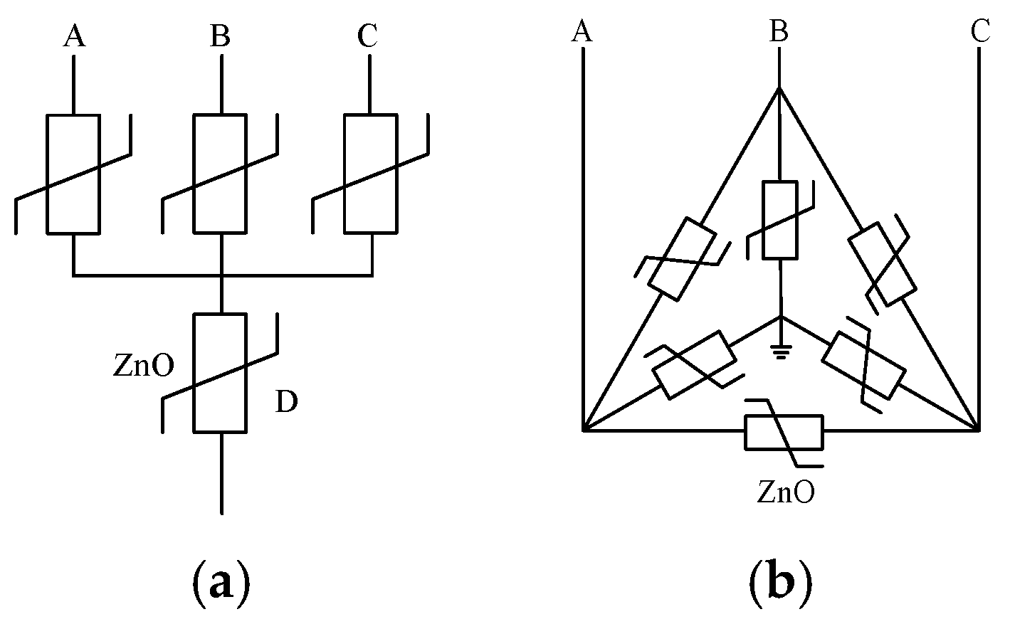
4.4. Install Combined Arrester
- (1)
- Not only can the four-star arrester and the six-phase arrester suppress the relative ground overvoltage in the same way as the three-star arrester, but they also have a good effect on the phase-to-phase overvoltage protection.
- (2)
- The installation of conventional arresters, four-star arresters, and six-phase arresters on the bus side mainly protects the bus-side overvoltage, which has a certain impact on the overvoltage of the shunt side but lacks protection; installation on the load side is also the main protection for the anti-side overvoltage, which has a certain impact on the bus side overvoltage, but the protection is insufficient.
- (3)
- The installation of arresters on the bus side alone cannot limit the overvoltage on the shunt side. Similarly, the installation of arresters on the shunt side alone cannot protect the overvoltage on the bus side, so the arresters on both sides are indispensable.
5. Conclusions
- (1)
- Because the root cause of the reignition of the first open phase is that the growth rate of the insulation strength at both ends of the vacuum circuit breaker is much smaller than the rising speed of the recovery voltage of the fracture, so the reignition is inevitable, the simple reignition overvoltage is not strong, and it is not enough to cause the accident to endanger safety. The root cause is the equivalent chopping overvoltage of the latter two phases caused by the repeated reignition of the first open phase.
- (2)
- The circuit breaker pre-switching or neutral-point switching is better for breaking and anti-overvoltage protection, but two circuit breakers need to be installed.
- (3)
- The resistance–capacitance absorber installed on the bus side can effectively eliminate the risk of overvoltage on the bus side, but it cannot prevent the occurrence of breaking overvoltage on the shunt side. Resistance–capacitance absorbers are installed on the shunt reactor side, and the overvoltage on the bus side and shunt reactor side is reduced to a certain extent, but it will still cause relatively strong overvoltage, especially phase-to-phase overvoltage.
- (4)
- The four-star arrester has obvious protection for relative ground and interphase overvoltage, but it has structural shortcomings, a high failure rate, and insufficient reliability. The effect of the installation of a six-phase arrester in a 35 kV system to suppress the breaking overvoltage of the shunt reactor is similar to that of the four-star arrester, but the reliability of the six-phase arrester is higher than that of the four-star arrester, so its comprehensive performance is better.
Author Contributions
Funding
Data Availability Statement
Conflicts of Interest
References
- Mou, H.-M.; Wang, J.-M.; Ji, Y.-C.; Wei, X.-X. The present situation of controllable reactor and its development of electrical application. Electr. Appl. 2006, 25, 1–4. [Google Scholar]
- Jiang, J.; Tang, H. Discussion on reactive power compensation and several reactive power compensation equipment. Heilongjiang Sci. Technol. Inf. 2010, 67, 132. [Google Scholar]
- Xia, C. A fault analysis of 35 kV dry-type shunt air-core reactor. Power Capacit. React. Power Compens. 2009, 1030, 44–45. [Google Scholar]
- Tai, B. 35 kV shunt reactor fault analysis. Guangdong Electr. Power 2011, 2, 24. [Google Scholar]
- Chen, C.; Zheng, X. Overvoltage analysis and suppression of 35KV switching shunt capacitor bank. Volkswagen Technol. 2012, 10, 87–90. [Google Scholar]
- Guan, Y.; Tang, Q.; Liu, W.; Xu, G. The generation mechanism of overvoltage when 40.5kV vacuum circuit breaker interrupts shunt reactor. Chin. J. Electr. Eng. 2012, 11, 124–132. [Google Scholar]
- Jin, B.; Li, D.; Cai, Z.; Chen, X.; Lv, D. Analysis of 35 kV parallel operation overvoltage fault example. Power Capacit. React. Power Compens. 2016, 37, 107–112. [Google Scholar]
- Jin, J.; Zheng, Y.; Chen, Y.; Wan, X. The switching overvoltage of 35 kV shunt reactor is controlled by the switching mode of the head end of the circuit breaker. Zhejiang Electr. Power 2017, 36, 55–58. [Google Scholar]
- Du, N.; Guan, Y.; Zhang, J.; Niu, J.; Yao, S.; Xu, G. Field test of 40.5 kV vacuum circuit breaker breaking shunt reactor. J. Tsinghua Univ. 2010, 4, 517–520. [Google Scholar]
- Du, N.; Guan, Y.; Zhang, J.; Niu, J.; Yao, S.; Xu, G. Overvoltage protection of 40.5 kV vacuum circuit breaker breaking shunt reactor. High Volt. Technol. 2010, 36, 345–349. [Google Scholar]
- GB/T 156-2007; Standard Voltage. National Voltage and Current Level and Frequency Standardization Technical Committee: Beijing, China, 2007.
- Yin, K. Research on Switching Overvoltage of Vacuum Switch and Its Protection; North China Electric Power University: Beijing, China, 2003. [Google Scholar]
- Du, N.; Guan, Y.; Zhang, J.; Niu, J.; Yao, S.; Xu, G. Three-phase modeling of vacuum circuit breaker breaking shunt reactor. High Volt. Electr. Appar. 2010, 46, 6–9. [Google Scholar]
- Yu, F. Simulation analysis of vacuum circuit breaker breaking shunt reactor. Zhejiang Electr. Power 2017, 36, 20–54. [Google Scholar]

| Reburning Times | Normal Breaking | 1 | 2 | 3 | 4 | 5 | |
|---|---|---|---|---|---|---|---|
| Overvoltage (kV) | |||||||
| The first open phase and anti-side-to-ground voltage | 42.7 | 46.0 | 49.5 | 54.8 | 60.5 | 66.8 | |
| The first open phase bus-side-to-ground voltage | 56.5 | 58.0 | 58.8 | 60.7 | 62.2 | 64.5 | |
| Phase-to-phase overvoltage on the parallel side | A-B | 77.6 | 81.9 | 86.4 | 93.3 | 100.7 | 108.9 |
| A-C | 77.4 | 81.7 | 86.2 | 93.2 | 100.5 | 108.7 | |
| B-C | 57.2 | 57.2 | 57.2 | 57.2 | 57.2 | 57.2 | |
| Bus-Side System to Ground Capacitance | Empty Busbar | 2 | 4 | |
|---|---|---|---|---|
| Bus-side overvoltage (kV) | Correspondingly | 105.6 | 103.6 | 98.6 |
| Interphase | 200.5 | 174.2 | 153.5 | |
| Parallel anti-side overvoltage (kV) | Correspondingly | 97.5 | 95.4 | 91.3 |
| Interphase | 178.8 | 178.7 | 173.0 | |
| Bus-side system to ground capacitance | 6 | 8 | 10 | |
| Bus-side overvoltage (kV) | Correspondingly | 97.9 | 96.4 | 93.8 |
| Interphase | 157.4 | 156.6 | 147.5 | |
| Parallel anti-side overvoltage (kV) | Correspondingly | 94.5 | 96.0 | 97.3 |
| Interphase | 170.2 | 177.2 | 170.4 | |
| Circuit Breaker Position | Bus-Side Overvoltage (kV) | Parallel Anti-Side Overvoltage (kV) | |||
|---|---|---|---|---|---|
| Correspondingly | Interphase | Correspondingly | Interphase | Turn to Turn | |
| Routine | 105.6 | 200.5 | 97.5 | 178.8 | 114.0 |
| Schematic Figure 14a | 51.9 | 78.1 | 79.6 | 115.6 | 85.2 |
| Schematic Figure 14b | 39.8 | 60.7 | 56.6 | 87.2 | 73.7 |
| Resistance–Capacitance Absorber Configuration | Installation Site | Bus-Side Overvoltage (kV) | |
|---|---|---|---|
| Correspondingly | Interphase | ||
| No configuration | / | 105.6 | 200.5 |
| 0.05 μF + 100 Ω | busbar side | 43.5 | 69.6 |
| And anti-side | 88.1 | 165.3 | |
| 0.1 μF + 100 Ω | busbar side | 41.7 | 70.8 |
| And anti-side | 89.1 | 164.8 | |
| 0.2 μF + 50 Ω | busbar side | 37.3 | 62.8 |
| And anti-side | 89.4 | 168.1 | |
| Resistance–capacitance absorber configuration | Installation site | Parallel anti-side overvoltage (kV) | |
| Correspondingly | Correspondingly | ||
| No configuration | / | 97.5 | 97.5 |
| 0.05 μF + 100 Ω | busbar side | 77.8 | 77.8 |
| And anti-side | 88.7 | 88.7 | |
| 0.1 μF + 100 Ω | busbar side | 77.7 | 77.7 |
| And anti-side | 87.7 | 87.7 | |
| 0.2 μF + 50 Ω | busbar side | 77.9 | 77.9 |
| And anti-side | 89.3 | 89.3 | |
| Arrester Configuration | Installation Site | Bus-Side Overvoltage (kV) | |
|---|---|---|---|
| Correspondingly | Interphase | ||
| No configuration | / | 207.7 | 232.4 |
| Three-star shaped lightning arrester | busbar side | 114.4 | 219.0 |
| And anti-side | 165.5 | 224.6 | |
| Bus side + parallel resistance side | 105.6 | 200.5 | |
| Four star lightning arrester | busbar side | 112.0 | 140.3 |
| And anti-side | 126.1 | 178.8 | |
| Bus side + parallel resistance side | 85.1 | 121.9 | |
| Six-phase lightning arrester | busbar side | 106.7 | 140.0 |
| And anti-side | 122.1 | 161.7 | |
| Bus side + parallel resistance side | 89.0 | 114.5 | |
| Arrester configuration | Installation site | Parallel anti-side overvoltage (kV) | |
| Correspondingly | Correspondingly | ||
| No configuration | / | 165.9 | 165.9 |
| Three-star shaped lightning arrester | busbar side | 143.5 | 143.5 |
| And anti-side | 106.9 | 106.9 | |
| Bus side + parallel resistance side | 97.5 | 97.5 | |
| Four-star lightning arrester | busbar side | 135.6 | 135.6 |
| And anti-side | 90.5 | 90.5 | |
| Bus side + parallel resistance side | 86.5 | 86.5 | |
| Six-phase lightning arrester | busbar side | 129.3 | 129.3 |
| And anti-side | 83.7 | 83.7 | |
| Bus side + parallel resistance side | 81.8 | 81.8 | |
| Comparison of Measure | Main Protective Effects | Protect the Shortcomings | Capitalized Cost | Other Deficiencies |
|---|---|---|---|---|
| Increase system outgoing lines | busbar side | And the anti-side cannot be protected | Nil | The line configuration cannot be arbitrarily changed. |
| Change the switching position | Bus side + parallel resistance side | Transient frequency increases | General | Not applicable to all shunt reactors |
| resistance-capacitance absorber | busbar side | And the anti-lateral protection effect is poor | General | Harmonics may be generated There are no current standards |
| Four star lightning arrester | Parallel anti-side/bus side | Protect only one side | Lower | It has a partial pressure effect and insufficient reliability. |
| Six-phase lightning arrester | Parallel anti-side/bus side | Protect only one side | General | Fewer running data |
Disclaimer/Publisher’s Note: The statements, opinions and data contained in all publications are solely those of the individual author(s) and contributor(s) and not of MDPI and/or the editor(s). MDPI and/or the editor(s) disclaim responsibility for any injury to people or property resulting from any ideas, methods, instructions or products referred to in the content. |
© 2025 by the authors. Licensee MDPI, Basel, Switzerland. This article is an open access article distributed under the terms and conditions of the Creative Commons Attribution (CC BY) license (https://creativecommons.org/licenses/by/4.0/).
Share and Cite
Chen, J.; Chen, X.; Feng, S.; Liu, X.; Liu, Q. Overvoltage Simulation Analysis and Suppression of Breaking in a 35 kV Shunt Reactor. Energies 2025, 18, 1274. https://doi.org/10.3390/en18051274
Chen J, Chen X, Feng S, Liu X, Liu Q. Overvoltage Simulation Analysis and Suppression of Breaking in a 35 kV Shunt Reactor. Energies. 2025; 18(5):1274. https://doi.org/10.3390/en18051274
Chicago/Turabian StyleChen, Jing, Xiaoyue Chen, Siying Feng, Xinmeng Liu, and Qin Liu. 2025. "Overvoltage Simulation Analysis and Suppression of Breaking in a 35 kV Shunt Reactor" Energies 18, no. 5: 1274. https://doi.org/10.3390/en18051274
APA StyleChen, J., Chen, X., Feng, S., Liu, X., & Liu, Q. (2025). Overvoltage Simulation Analysis and Suppression of Breaking in a 35 kV Shunt Reactor. Energies, 18(5), 1274. https://doi.org/10.3390/en18051274