Review

Gas Production and Storage Using Hydrates Through the Replacement of Multicomponent Gases: A Critical Review

1
School of Energy and Power Engineering, North University of China, Taiyuan 030051, China
2
Hebei Engineering Research Center of Advanced Energy Storage Technology and Equipment, School of Energy and Environmental Engineering, Hebei University of Technology, Tianjin 300401, China
3
Key Laboratory of Ocean Energy Utilization and Energy Conservation of Ministry of Education, Dalian University of Technology, Dalian 116024, China
4
School of Marine Science and Technology, Northwestern Polytechnical University, Xi’an 710072, China
5
National Innovation Platform (Center) for Industry-Education Integration of Energy Storage Technology, Xi’an Jiaotong University, Xi’an 710049, China
6
Key Laboratory of Shanxi Province for Solar Thermal Technology, Taiyuan 030051, China
*
Authors to whom correspondence should be addressed.
Energies 2025, 18(4), 975; https://doi.org/10.3390/en18040975
Submission received: 24 January 2025 / Revised: 12 February 2025 / Accepted: 15 February 2025 / Published: 18 February 2025

Abstract

:
With the continuous growth of global energy demand and the gradual depletion of traditional fossil energy reserves, natural gas hydrates have attracted widespread attention as a potential clean energy source due to their vast reserves and wide distribution. Although various extraction methods, including depressurization, thermal stimulation, chemical inhibitors, and displacement methods, have been proposed, there are still challenges, such as low extraction efficiency, poor sustainability, and high costs, making it difficult to achieve large-scale engineering applications. Among these, the use of gases such as CO2 for displacement extraction of natural gas hydrates can both develop hydrate resources and sequester CO2, achieving a win–win situation for resource development and greenhouse gas reduction. This paper provides a detailed review of the multi-gas displacement extraction technology for natural gas hydrates, systematically summarizes the latest progress in thermodynamic and kinetic studies, analyzes the technical advantages and feasibility of combining displacement methods with traditional techniques, and explores the effects of multi-gas mixtures, such as N2, CO2, and H2, and their ratios on hydrate extraction efficiency. Finally, this paper summarizes the technical challenges faced by displacement extraction methods for hydrates and offers future research directions to promote the development of multi-gas displacement technology for natural gas hydrates.

1. Introduction

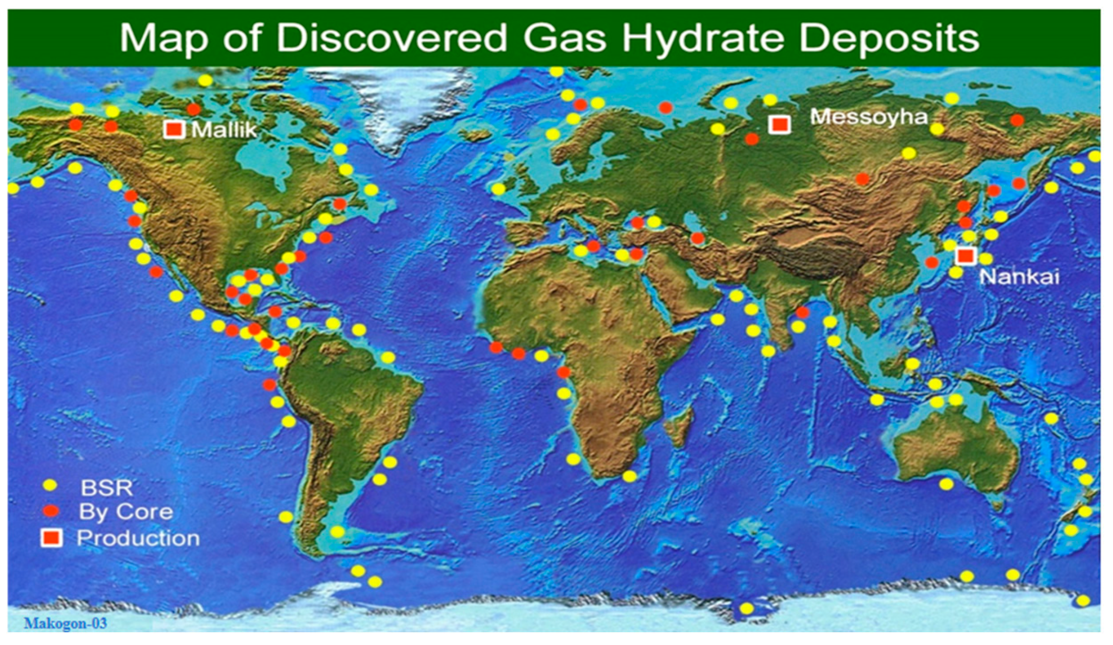
1.1. Natural Gas Hydrate

Natural gas hydrate is a solid, ice-like substance formed by natural gas molecules and water molecules under low-temperature and high-pressure conditions. For every 1 cubic meter of solid hydrate that decomposes, approximately 163 cubic meters of natural gas are released. The total carbon stored in global hydrate resources is roughly twice the total carbon stored in all other conventional fossil fuels, including oil, coal, and conventional natural gas [1,2]. This compound is considered a clean energy source, as it produces lower carbon dioxide emissions during combustion compared to traditional fossil fuels, helping to reduce environmental pollution and mitigate global climate change issues [1]. Predictions suggest that there are vast natural gas hydrate resources on Earth, with reserves exceeding 15 × 1012 tons. If 17% to 20% of this resource could be exploited, it would be sufficient to provide ample energy supply for the next 200 years. Natural gas hydrate deposits are mainly distributed in two regions: one is the high-latitude land covered by permafrost, such as Siberia, Alaska, and the Canadian Archipelago; the other is the deep-sea sedimentary layers, particularly in the continental shelf and slope areas, especially in water depths ranging from 300 to 3000 m, such as the South China Sea depression in the western Pacific, the Blake Plateau in the western Atlantic, and the Arabian Sea Trench in the Indian Ocean. After nearly thirty years of global joint exploration, utilizing technologies such as seismic wave detection, seabed sampling, and deep-sea drilling, more than 230 natural gas hydrate deposits with industrial extraction potential have been identified worldwide. Figure 1 shows the geographical distribution, abundance levels, and the forms in which natural gas hydrates exist on land and in the ocean. In the figure, yellow circles (BSR) represent regions where natural gas hydrates have been discovered through the Bottom Simulating Reflector (BSR) method. BSR is an important seismic exploration marker for identifying natural gas hydrates. Red circles (by core) indicate areas where the presence of natural gas hydrates has been confirmed through core sampling. Core sampling is a direct method of obtaining underground material samples, which can definitively prove the existence of natural gas hydrates. Red squares (production) represent areas where natural gas hydrate extraction has already taken place. The figure marks several typical locations, such as Mallik in Canada, Messoyakha in Russia, and Nankai in Japan. From the map, it is evident that natural gas hydrate deposits are widely distributed across the globe. In the ocean, they are mainly concentrated along the continental margins, while on land, they are primarily found in high-latitude polar regions, such as those near the Arctic, demonstrating the immense market potential and sustainable development advantages of natural gas hydrates [3]. Natural gas hydrate can be used in various fields, such as civilian and industrial fuels, chemicals, and power generation, offering broad application prospects. It forms a complete industrial chain, from upstream exploration and development to midstream transportation and storage and downstream comprehensive utilization. Research into its extraction technology can not only accelerate energy technological innovation and industrialization but also provide significant support for global energy structure optimization, environmental protection, and climate change mitigation. With ongoing technological advancements, natural gas hydrate is expected to become an important component of the global energy system, playing a key role in the future energy transition [4].

1.2. Natural Gas Hydrate Extraction

1.2.1. Traditional Natural Gas Hydrate Extraction Methods

The extraction methods for natural gas hydrates are still in the research and testing stages. Despite facing numerous challenges, several technological solutions have been proposed. Most existing extraction methods are based on adjusting the pressure and temperature of the hydrates, shifting them from the stable hydrate zone to the dissociation zone, thereby enabling dissociation [6]. There are three main traditional methods for extracting natural gas hydrates: depressurization, thermal stimulation, and chemical inhibitor injection. The advantages and disadvantages of these three methods are shown in Table 1 [7,8,9].
The depressurization method used in the extraction of natural gas hydrates is a widely used technique. Its basic principle is to lower the pressure in the hydrate reservoir to disrupt the phase equilibrium of the hydrates, causing the dissociation of the hydrates into gas (such as CH4) and water, thereby enabling the extraction of natural gas [10,11]. Currently, two main approaches are used to achieve depressurization: (1) the use of low-density drilling mud technology, which aims to achieve a depressurization effect; (2) the use of pump pressure technology to extract free gas and other fluids from beneath the natural gas hydrate reservoir to achieve the depressurization goal [12].
The thermal stimulation method is a technique that promotes natural gas release by heating the hydrate reservoir [13]. Its basic principle is to provide heat to the natural gas hydrate reservoir, increasing the temperature, thereby causing the dissociation of the hydrates into gas and water and releasing natural gas [14]. The implementation methods include thermal fluid injection, electric heating, and geothermal heating, among others [15]. Table 2 lists the advantages and disadvantages of different thermal extraction methods.
The chemical inhibitor injection method prevents the formation of hydrates or promotes their dissociation by injecting chemical inhibitors, thereby improving natural gas recovery efficiency [16]. This method is particularly suitable for deep-sea or polar natural gas hydrate reservoirs, as hydrates in these regions are typically stable due to temperature and pressure conditions and are not easily dissociated naturally. Chemical inhibitors can effectively control the formation and dissociation of hydrates. Common chemical inhibitors, as shown in Table 3, include thermodynamic hydrate inhibitors, kinetic hydrate inhibitors, anti-agglomerants, and dual-function hydrate inhibitors [17].
In the extraction process of natural gas hydrate, a combination of various traditional methods is often employed to enhance extraction efficiency. For example, the combination of depressurization and thermal stimulation. By reducing pressure, the stability of the hydrate is lowered, and the heating process accelerates the decomposition of the hydrate, thereby promoting the release of natural gas and shortening the extraction cycle. The advantage of this method lies in its ability to accelerate gas release and increase extraction rates. However, the thermal stimulation process requires a large amount of energy and may cause temperature fluctuations, which can affect the stability and continuity of extraction. Additionally, prolonged depressurization may lead to instability in the hydrate reservoir, affecting the gas recovery rate [12].
Furthermore, the combination of depressurization and chemical inhibitors can also significantly improve extraction efficiency. Chemical inhibitors can suppress the re-crystallization of the hydrate during depressurization, reducing instability and accelerating hydrate decomposition at lower temperatures, thereby maintaining high gas output [10,11]. However, chemical inhibitors are expensive, and their potential environmental impact needs to be evaluated and monitored, as long-term use may pose environmental risks.
Moreover, combining thermal stimulation with chemical inhibitors can prevent the re-crystallization of the hydrate at lower temperatures during the heating process, thus maintaining extraction efficiency. Heating helps accelerate the decomposition of the hydrate, while inhibitors further stabilize the decomposition process [16]. However, this method requires a large amount of energy input, and the use of chemical inhibitors is costly. Additionally, the ratio of heat energy to inhibitor use must be carefully controlled, as excessive use may lead to environmental issues. Therefore, while coupling methods can improve extraction efficiency, their implementation must carefully consider energy consumption, costs, and environmental impact.

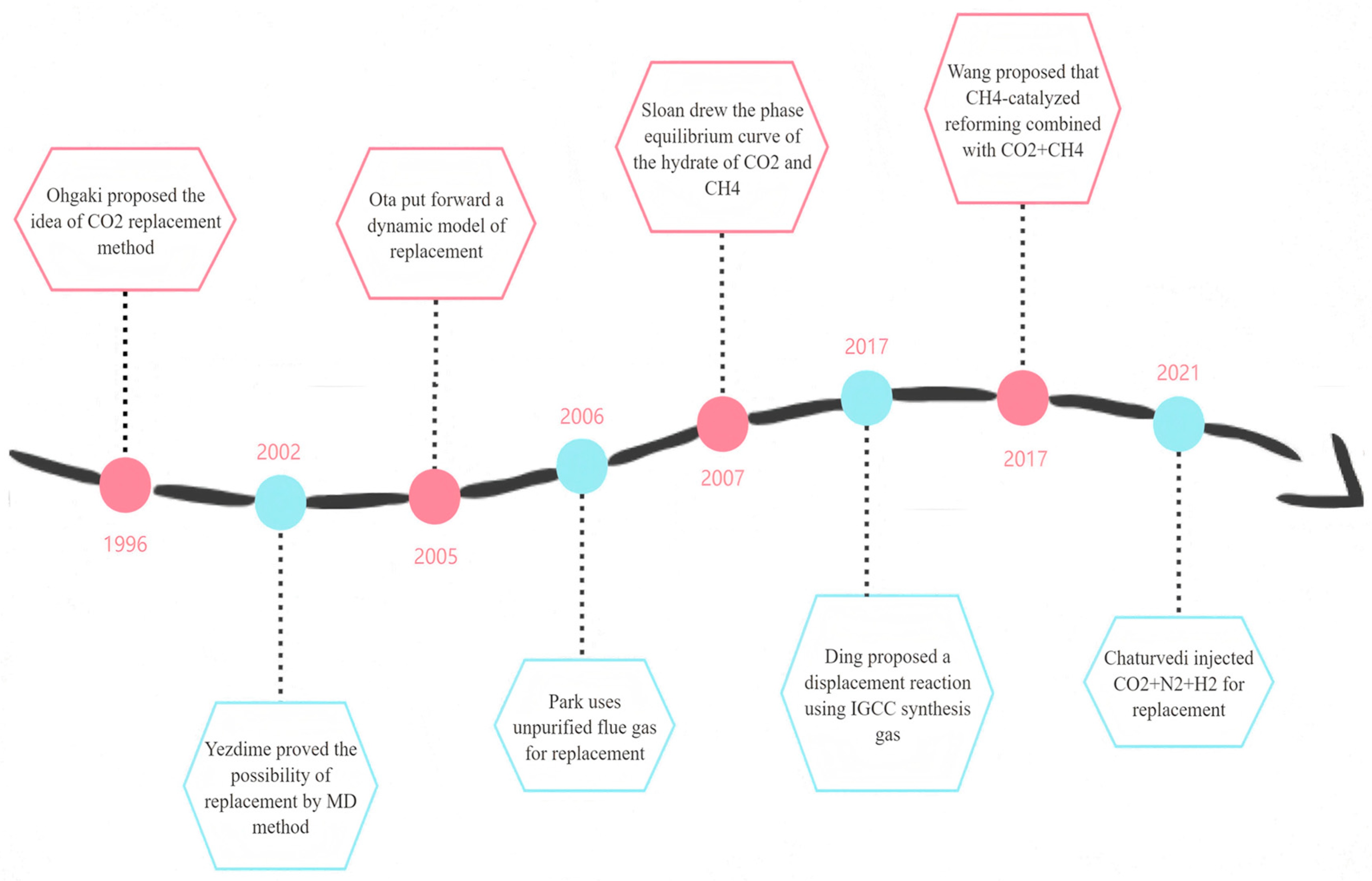
1.2.2. CO2 and CH4 Displacement Method

Traditional methods promote the natural decomposition of hydrate into natural gas by breaking the phase equilibrium of hydrates in their initial state. However, when exploring the feasibility and economic viability of various extraction technologies, the stabilizing support role of natural gas hydrates in the surrounding formation cannot be overlooked. While traditional extraction methods promote hydrate decomposition, they may also weaken the formation’s stability, potentially triggering geological disasters such as earthquakes and underwater landslides, which highlights the limitations of these extraction methods [18]. On the other hand, with the rapid development of human society and the surge in greenhouse gas emissions, this has become a major environmental issue that urgently needs to be addressed. In this context, CO2 sequestration technology, as an effective means to promote CH4 extraction, reduce CO2 emissions, and alleviate the greenhouse effect, has become increasingly important. Therefore, in the exploration of natural gas hydrate extraction methods, it is also essential to actively consider how to integrate CO2 sequestration technology to achieve a win–win situation for both energy development and environmental protection [19]. Figure 2 shows the development history of the displacement method research.
The principle of the displacement extraction method is to inject CO2 into the submarine hydrate-bearing zone, replacing CH4 in the hydrate with CO2, thereby enabling the safe and efficient extraction of CH4 hydrate while also achieving the long-term stable geological sequestration of CO2 [20]. In addition, during the hydrate displacement extraction process, the generated CO2 hydrate helps maintain the geological stability of the hydrate reservoir, effectively preventing formation collapse and instability caused by the phase transition and decomposition of CH4 hydrate. In this process, CO2 and CH4 in the hydrate undergo a substitution reaction through physical and chemical processes, with CO2 being fixed in the form of a hydrate, while the original CH4 is released as gas [21]. The displacement method has strong technical adaptability and is capable of operating effectively under different temperature and pressure conditions, especially in low-temperature, high-pressure reservoirs. It offers good technical and economic feasibility and broad applicability, contributing to global emission reduction goals and the sustainable utilization of energy.
Figure 2. The development history of the research on replacement method [22,23,24,25,26,27,28,29].
Energies 18 00975 g002

2. Structure and Properties of Hydrates

2.1. Crystal Structure of Hydrates

Hydrates have a crystal structure similar to that of molecular sieves, where water molecules are connected by hydrogen bonds to form a regular lattice structure. These lattice units create a cage-like structure that can encapsulate and store gas molecules. Depending on the size and quantity of the gas molecules and their interaction with water molecules, the structure of hydrates is generally classified into three types: Type I, Type II, and Type H. Due to its simplicity and stability, the most commonly found hydrate in nature is Type I, composed of smaller gas molecules such as CH4 (which makes up more than 90%). These are commonly referred to as methane hydrates [30,31].
The cage structure of hydrates is not always completely filled, and there are certain vacancies within the cages. These vacancies allow gas molecules to enter the cages and be “encapsulated.” The stability of the hydrate and its gas storage capacity typically depend on the size, shape, and degree of matching between the vacancies in the cages and the gas molecules. During the formation of hydrates, gas molecules enter these vacancies and are surrounded by water molecules, forming a stable solid structure under specific temperature and pressure conditions [21,32]. For example, in Type I hydrates, the smaller 56-cage mainly accommodates one gas molecule, while the larger 512-cage can hold multiple small gas molecules. The presence of vacancies and the entry of gas molecules allow hydrates to store a large amount of gas, which is a key feature of hydrates as a medium for gas storage.
During the formation of hydrates, gas molecules are surrounded by water molecules and embedded into vacancies within the cages. Once the gas molecules enter the cages, they interact with the water molecules primarily through van der Waals forces and hydrogen bonding. Due to the small size and chemical inertness of the gas molecules, they can be stably surrounded by water molecules, forming a stable “cage-like” structure [32]. The size, type, temperature, and pressure of the gas molecules collectively determine the formation, stability, and storage capacity of hydrates. Suitable gas size and shape, low temperature, and high-pressure conditions, as well as the appropriate type and concentration of gas, facilitate the stable formation and efficient storage of hydrates. With changes in temperature and pressure, hydrates can undergo thawing or gas release, leading to the decomposition of the hydrate and the release of gas [33].
In the process of replacing methane with carbon dioxide for the extraction of natural gas hydrates, the maximum theoretical displacement efficiency is 75%. This phenomenon is primarily related to the crystalline structure of the hydrate and the interactions between gas molecules. Natural gas hydrates typically have a cage-like crystalline structure, which is mainly classified into two types: Structure I (S-I) and Structure II (S-II). In these hydrate structures, carbon dioxide molecules usually replace methane molecules. However, since carbon dioxide molecules are larger than methane molecules, carbon dioxide cannot completely replace all the methane molecules, resulting in a maximum displacement efficiency of about 75%.
In Structure I hydrates, methane molecules occupy the small cages, while carbon dioxide molecules preferentially fill the larger large cages. In Structure II hydrates, carbon dioxide molecules also preferentially occupy the larger cages, similar to the large cages in Structure I. These structural differences and the size disparity between carbon dioxide and methane molecules limit the complete replacement of methane by carbon dioxide [30,31,33].

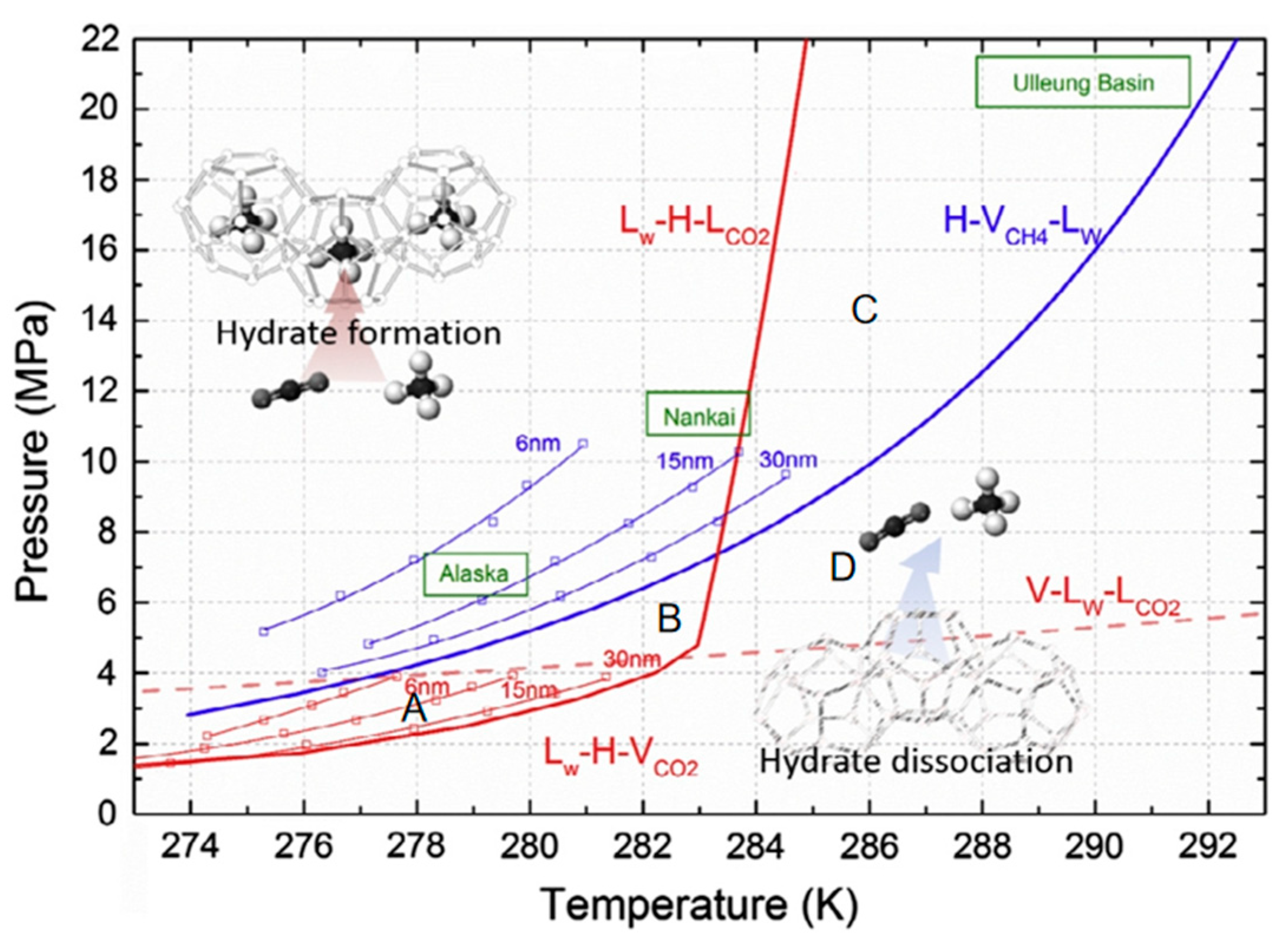
2.2. Thermodynamic Study

Thermodynamic studies mainly focus on the formation phases of hydrates, stability regions, and the changes in free energy during the replacement process. Through thermodynamic analysis, the stability of CO2 and CH4 in hydrates and their replacement behavior under different temperature and pressure conditions can be predicted [34]. Additionally, research on phase equilibrium helps to determine stable operating conditions, control the thermodynamic driving forces of replacement reactions, study the dynamic processes of gas diffusion and exchange, ensure thermodynamic and kinetic stability during extraction, and provide a scientific basis for the long-term sequestration of CO2 and environmental safety [26].

2.2.1. Thermodynamic Characteristics of Replacement Reactions

According to the basic principles of chemical thermodynamics, spontaneous reactions always proceed in the direction of decreasing Gibbs free energy. Yezdimer et al. [23] demonstrated through molecular dynamics simulations that the Gibbs free energy of CO2 hydrate is lower than that of CH4 hydrate. Additionally, the Gibbs free energy of the replacement reaction is negative, indicating that the reaction can proceed spontaneously [24]. From the perspective of phase change heat, the heat released during the decomposition of CO2 hydrate (57.98 kJ/mol) is greater than the heat absorbed during the decomposition of CH4 hydrate (54.94 kJ/mol). Therefore, the heat required for the decomposition of CH4 hydrate can be provided by the heat released during the formation of CO2 hydrate, and the replacement reaction does not require additional heat input from external sources [35,36].
Akihiro [37], in his study of the phase equilibrium temperature and pressure of CH4 and CO2 hydrates below the freezing point, found that they follow the same pattern. During the replacement process, a mixed gas of CO2 and CH4 is generated. Goel [38], through experimental research on the formation process of CH4 and CO2 hydrates, plotted phase equilibrium curves for mixtures of CO2 and CH4 at different ratios. He found that as the CO2 content increased, the phase equilibrium pressure of the mixed gas decreased while the phase equilibrium temperature increased. CO2 hydrate remains stable within the temperature range of 260–270 K and the pressure range of 0.6–1.7 MPa, while CH4 hydrate is not easily formed. Circone et al. [39] further demonstrated through experiments that, within a specific temperature and pressure range (0.1 MPa, 168–218 K), CH4 hydrate can decompose while CO2 hydrate remains stable. Xie et al. [40], by fitting experimental data using 10 thermodynamic models, showed that from the perspective of adsorption thermodynamics, the adsorption amount of CO2 is larger than that of CH4 under the same conditions, with an adsorption strength range of 16.71–35.65 kJ/mol, which is higher than CH4’s range of 12.48–28.90 kJ/mol. This indicates that shale adsorbs CO2 more strongly. Gas adsorption is a spontaneous and enthalpy-driven process, with a negative ΔG indicating spontaneous adsorption. Furthermore, the absolute value of ΔG for CO2 is smaller than that for CH4, meaning the CO2 adsorption process is more likely to occur.

2.2.2. Stability of Hydrates and Gas Distribution Behavior

The stability and formation process of hydrates is closely related to the occupancy state of gas molecules within the hydrate crystal structure. Methane hydrate is typically stable at lower temperatures and higher pressures, while carbon dioxide hydrate has a relatively wider range of stable temperatures and pressures, and its formation conditions are more easily achieved compared to methane hydrate [26]. Additionally, the decomposition process of hydrates plays a significant role in gas replacement behavior and energy release. Therefore, a thorough study of the phase diagram and stability of hydrates is crucial for the development of these applications [41].
Ohgaki et al. [22] proposed a method for extracting natural gas hydrates using CO2 substitution. This method involves introducing CO2 gas into the gas–liquid hydrate three-phase system of CH4, forming a gas–liquid hydrate equilibrium system containing both CO2 and CH4. Figure 3 shows the thermodynamic equilibrium curves for pure CH4 and pure CO2 hydrates, as well as the gas–liquid phase equilibrium curve for CO2. The thermodynamic trends for the two natural gas hydrates can be summarized as follows: under the presence of gaseous CO2, the formation conditions for pure CO2 hydrate are milder than those for pure CH4 hydrate. When gaseous CO2 is injected into the methane hydrate layer, the unstable methane hydrate dissociates, releasing methane gas and liquid water. Subsequently, the melted water reacts with the injected CO2 and spontaneously forms a more stable CO2 hydrate as the product of the entire gas exchange reaction [42]. In the figure, areas A and B are located above the H2O-hydrate-CO2 equilibrium curve and below the H2O-hydrate-CH4 equilibrium curve, respectively. Thermodynamic analysis indicates that these regions suggest that, under specific temperature and pressure conditions, gaseous methane (CH4) and CO2 hydrate can coexist. Therefore, when CO2 is injected into the CH4 hydrate layer, CO2 can be stored as a hydrate. This phenomenon reveals that CO2 hydrate (CO2·nH2O) is more stable than methane hydrate (CH4·nH2O) [43]. Under the same environmental conditions, CO2 can form and stabilize hydrates at lower temperatures and higher pressures, while CH4 hydrate requires higher temperatures or lower pressures to remain stable.
The process of CO2 replacing methane occurs above the methane hydrate phase equilibrium line to ensure that CO2 can effectively replace methane. The reaction must take place under conditions where methane hydrate remains stable. Only above the methane hydrate phase equilibrium line does methane hydrate maintain a stable solid structure, providing a basis for CO2 molecules to substitute into the lattice. Below the phase equilibrium line, methane hydrate will spontaneously decompose, and there will be no stable methane hydrate structure available for CO2 to carry out the replacement reaction. At the pressure–temperature conditions above the phase equilibrium line, the process of CO2 and water molecules forming a hydrate is thermodynamically more favorable. Higher pressure and appropriate temperature conditions help CO2 molecules overcome energy barriers to enter the hydrate lattice and replace methane molecules. This thermodynamic advantage drives the replacement reaction towards the formation of CO2 hydrate and the release of methane [42]. In the process of CO2 replacing methane, if the pressure–temperature conditions fluctuate near the methane hydrate phase equilibrium line, methane hydrate may re-form, encapsulating unreacted CO2 or blocking pore channels, thus reducing the replacement efficiency. To minimize this risk, stable conditions above the phase equilibrium line should be maintained to ensure the continuous progress of the replacement reaction [41]. Additionally, if the CO2 concentration is too high or poorly controlled, excessive formation of CO2 hydrate at the sediment surface may occur, creating a dense shell that hinders CO2 diffusion and methane release, thereby reducing replacement efficiency. By properly controlling the CO2 injection rate and reaction conditions, this issue can be avoided, maintaining a high replacement efficiency. Therefore, controlling the replacement process above the methane hydrate phase equilibrium line ensures the stable existence of methane hydrate while reducing the risks of reformation of methane hydrate and excessive formation of CO2 hydrate.
This conclusion indicates that CO2 hydrate has a clear thermodynamic advantage, as it not only forms more easily under natural sediment conditions but also has greater potential to replace methane hydrate [44]. The figure also presents the equilibrium data between the liquid and gas phases of CO2, which is crucial for understanding the behavior of CO2 in hydrates. These data can help researchers better predict the conversion efficiency of CO2 during the replacement process of natural gas hydrates, thereby optimizing the overall process of CO2 sequestration and natural gas extraction.
At the same time, during the exchange process, because of their smaller size and stronger polarity, CO2 molecules can more easily be embedded into the hydrate cages, especially in Structure I hydrates, where CO2 can effectively replace CH4 molecules. However, the competitive entry of CO2 and CH4 for entry may result in changes to the stability of the hydrates. This leads to the hindrance of the displacement process, with the main limiting factors including thermodynamics, competitive adsorption, kinetics, and hydrate stability. CO2 replacement of methane requires specific temperature and pressure conditions, and unfavorable temperature and pressure may result in low replacement efficiency. At the same time, the competitive adsorption of CO2 and methane in the hydrate structure may affect the replacement effect, especially when methane has already been adsorbed. Kinetically, the diffusion rate of CO2 is relatively slow, and the size and structure of the hydrate pores also influence the rate of the displacement reaction. Furthermore, excessive CO2 displacement may alter the stability of the hydrate, causing hydrate decomposition or instability. Finally, the entire displacement process often requires a long time, especially under low temperatures and high pressure, which limits large-scale applications. Therefore, the distribution and phase behavior of gas molecules in hydrates are not only central to the formation, stability, and dissociation processes of hydrates but are also key factors in the study of hydrate utilization and its environmental impacts [45].

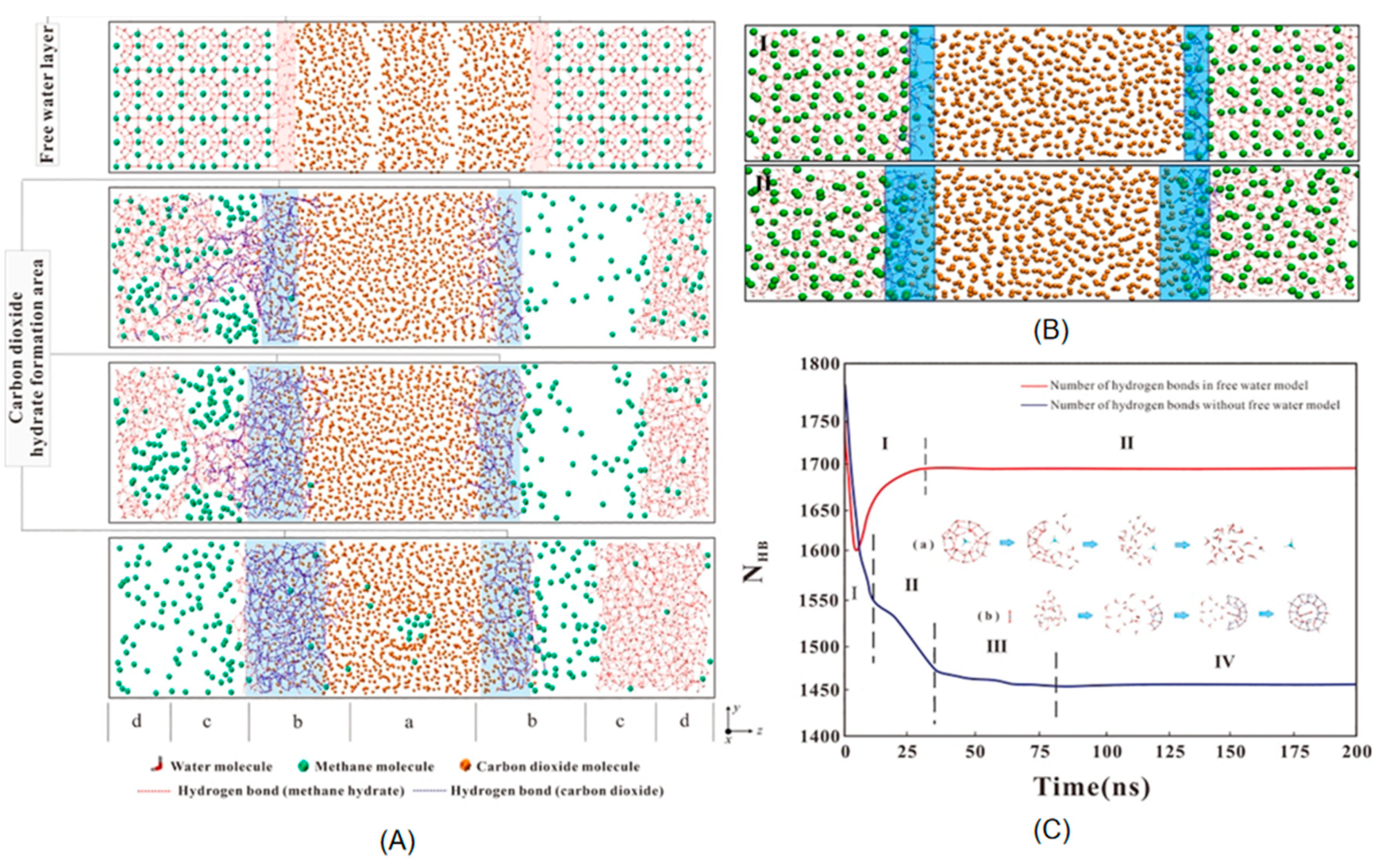
2.3. Kinetic Studies

Kinetic studies primarily focus on several key factors in the gas displacement process, including reaction rates, diffusion mechanisms, and dynamic changes at the interface. Although thermodynamically favorable conditions for gas displacement may exist, the actual rate and efficiency of the displacement process are still constrained by various kinetic factors. Therefore, even when thermodynamic conditions are met, the actual occurrence of the gas displacement process is still limited by these kinetic factors, requiring further experimental studies and modeling for optimization [46].

2.3.1. Gas Diffusion and Exchange Rate

The diffusion process of gas within the hydrate is crucial to the gas displacement rate. In natural gas hydrates, gas molecules diffuse into the hydrate’s cage structure, displacing the original gas molecules inside the hydrate [44]. This process involves several key steps, including the entry of gas molecules from the external environment into the hydrate interface, penetration through the solid structure of the hydrate, and exchange with the existing gas molecules.
The diffusion rate of CO2 is typically higher than that of CH4, which may be due to the larger size of CO2 molecules, resulting in a more complex spatial occupation within the hydrate’s cage structure. The structure of the hydrate is typically formed by water molecules arranged in a cage-like pattern, creating pore structures to trap gas molecules [18]. Due to the larger molecular volume of CO2, CO2 molecules may be more likely to aggregate and interact with each other within the hydrate’s cage compared to methane molecules, thereby affecting its diffusion behavior [23].
In the gas displacement process, gas exchange primarily occurs at the gas–hydrate interface. This process refers to the interaction between gas molecules and water molecules within the hydrate, causing the gas molecules to enter the hydrate structure and potentially displace the original gas molecules [47]. During this process, a larger gas–hydrate interface area helps accelerate gas exchange. If the hydrate particles are smaller in size, the surface area per unit volume increases, leading to more contact between gas molecules and the hydrate, which in turn enhances the exchange rate. Additionally, if the hydrate structure is more loosely packed or has larger pore sizes, the diffusion rate of gas molecules within the hydrate is faster, improving the efficiency of gas exchange. Conversely, if the hydrate structure is more compact, the diffusion rate of gas molecules is restricted, and the displacement process may slow down [44].

2.3.2. Reaction Mechanisms in the Displacement Process

The process of CO2 displacing methane hydrate is a complex and dynamic multi-step reaction that involves competition, diffusion, and the reorganization of the hydrate structure between gas molecules. In this process, CO2 molecules compete with methane molecules for occupancy of the hydrate’s empty cages. This process is not merely a simple gas exchange but also involves a series of changes related to the hydrate structure. A schematic diagram of the two CH4 hydrate replacement mechanisms is shown in Figure 4 [46].
The CO2-CH4 hydrate replacement process can be divided into three steps: First, CO2 contacts the surface layer of the CH4 hydrate. As CO2 enters the hydrate surface, the cage-like structure of the methane hydrate begins to break down, causing a portion of the methane gas to rapidly decompose and be released. At this point, methane gas escapes from the hydrate, and the structure of the surface layer of the hydrate is disrupted. As the displacement process progresses, CO2 and CH4 quickly combine with surrounding free water molecules, forming a mixed hydrate layer. Finally, CO2 gas slowly diffuses into the interior of the hydrate and continues to displace the methane molecules within the hydrate structure. As CO2 penetrates deeper into the hydrate, methane molecules originally occupying the internal cages are gradually replaced, and methane gas escapes outward, completing the displacement process. This stage of diffusion is relatively slow and depends on factors such as temperature, pressure, and the pore structure of the hydrate [20].

2.3.3. Kinetic Characteristics of the Displacement Reaction

Studies have shown that the CO2-CH4 displacement process is a complex dual mechanism significantly influenced by the occupancy of the hydrate cages. Bai et al. [48] conducted an in-depth study of this process using molecular dynamics (MD) simulations, revealing that the chemical potential changes of CO2 molecules lead to the decomposition of methane hydrate and, by disturbing the structure of the hydrate, cause CH4 molecules to be released from the cage-like structure. Nakano et al. [49] found experimentally that CO2 diffuses faster than methane (CH4) in the hydrate, proving that the CO2-CH4 hydrate displacement method is kinetically feasible. Tung et al. [50] pointed out that liquid CO2 can directly replace methane (CH4) in the hydrate without the need for the decomposition process. Other studies [51] explored the microscopic behavior of CO2 and methane hydrates during the displacement reaction by using high-pressure reactors under different temperature and pressure conditions combined with molecular dynamics simulations, as shown in Figure 5. Figure 5A,B show the process of CO2 replacing methane hydrate with and without free water. Figure 5C demonstrates that during the free water replacement process, the number of hydrogen bonds gradually decreases, and the decomposition rate of methane hydrate and the formation rate of CO2 hydrate show different slopes at each stage. The results indicate that within a certain temperature and pressure range, as temperature and pressure increase, the displacement efficiency gradually improves.
Researchers have also conducted in-depth studies on the formation and decomposition mechanisms of hydrates using visualization techniques such as neutron diffraction, Raman spectroscopy, and nuclear magnetic resonance (NMR). For example, Uchida et al. [52] used Raman spectroscopy to confirm that the CO2-CH4 hydrate displacement reaction primarily occurs at the surface layer of the CH4 hydrate. The results showed that during the displacement process, the concentration of methane (CH4) gas in the gas phase gradually increased over time, but the rate of increase slowed down as the reaction progressed. This indicates that as the displacement reaction advances, CH4 molecules in the hydrate are gradually replaced by CO2, leading to a stabilization in the concentration of CH4 gas. Kuang et al. [53] studied the microstructural evolution of CO2 hydrates in porous media using NMR technology, revealing the structural changes of CO2 hydrates in the pore space and their interactions with the surrounding environment under different conditions. Additionally, by analyzing the variation in pore water volume distribution with depth in sand layers under different storage conditions (as shown in Figure 6), they found differences in the formation locations of hydrates in porous media, confirming that CO2 hydrates nucleate randomly in porous media and preferentially form in pore spaces. Their research provides an important theoretical basis for understanding the behavior of CO2 hydrates in underground storage and the development of natural gas hydrates. Farahani et al. [54] compared the formation and decomposition of CH4 hydrates in synthetic and natural sediment samples. Through experimental analysis, they found that CH4 hydrates in natural sediments exhibited different kinetic characteristics during formation and decomposition compared to synthetic samples. This discovery provides new insights into the stability of natural gas hydrates, storage conditions, and gas displacement phenomena, presenting both challenges and opportunities for the exploitation and utilization of hydrates.
In the practical process of CO2 displacement for natural gas hydrate exploitation, thermodynamics and kinetics work together in a complementary manner. Thermodynamic studies provide the phase equilibrium conditions and driving forces for the displacement process, while kinetic studies reveal the reaction rates, diffusion mechanisms, and influencing factors of the process. By combining thermodynamic and kinetic models, researchers can optimize the various operating conditions involved in the extraction process to achieve more efficient gas displacement. In terms of temperature and pressure control, thermodynamic models can determine the optimal temperature and pressure ranges to promote the CO2 displacement of methane. Kinetic simulations, on the other hand, can help researchers predict the reaction rates and efficiency under different temperature and pressure conditions, thereby identifying the most suitable operating conditions.

3. Combined Enhancement of Displacement Method and Traditional Methods

The displacement method, as a novel natural gas extraction technology, holds significant potential in improving extraction efficiency, reducing greenhouse gas emissions, and promoting sustainable extraction. However, its high cost, technical complexity, and environmental risks are key challenges that need to be addressed for its commercialization [46]. Therefore, researchers worldwide have conducted extensive studies on enhancing the CO2-CH4 displacement process, exploring various aspects from the macro-level displacement process to the micro-level displacement mechanisms. The aim is to find an efficient enhancement method that comprehensively considers factors such as economic cost, environmental protection, and process complexity. Table 4 presents a comparison of the impacts of the displacement method combined with various traditional methods of natural gas extraction.

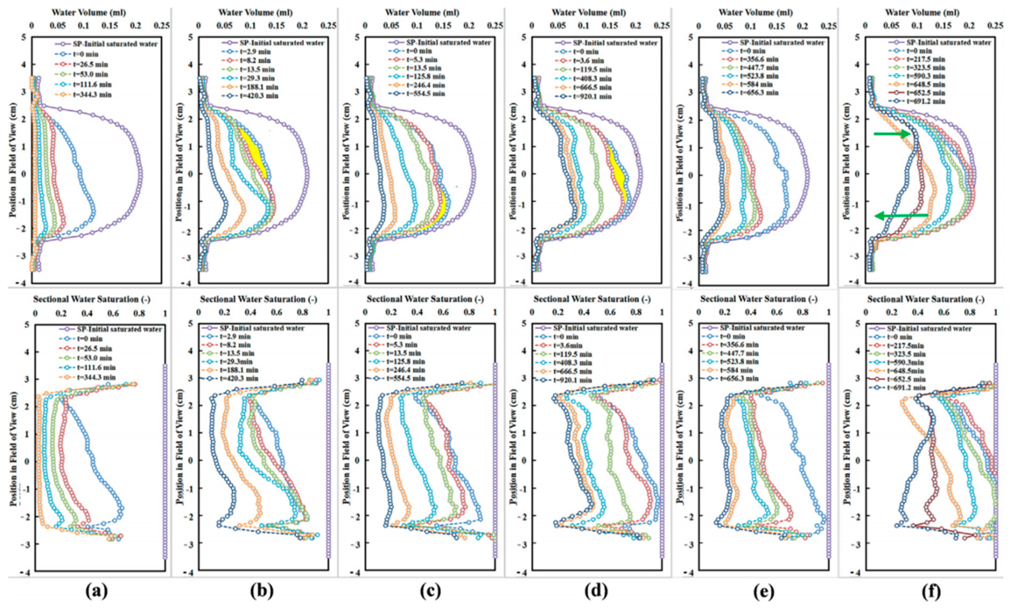
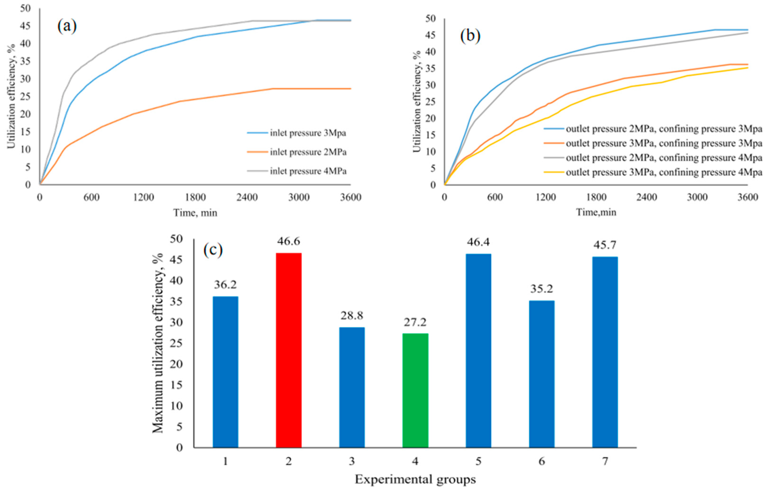
3.1. Combined Extraction of Displacement Method and Depressurization Method

The traditional depressurization method has been applied in natural gas hydrate extraction to some extent. However, during the depressurization process, the dissociation of hydrates is an endothermic reaction, leading to a gradual decrease in methane production and a continuous drop in reservoir temperature. At the same time, a large amount of water is produced during depressurization, which not only further reduces gas production efficiency but may also cause a series of safety issues. This presents numerous challenges for the practical application of this method [21]. In contrast, the displacement method promotes hydrate dissociation by injecting external gases (such as CO2) to replace methane molecules in the hydrate. Combining depressurization with the displacement method can fully leverage the synergistic effects of both, significantly improving methane release efficiency [48,55].
The advantage of this combined method is that the depressurization process creates the necessary low-pressure environment for the injection of displacement gases, ensuring that the displacement gas can effectively penetrate the hydrate layer. Meanwhile, the displacement method accelerates the dissociation of the hydrate through gas exchange, greatly enhancing the release rate of CH4 [47]. Specifically, when CO2 is used as the displacement gas, it can undergo a substitution reaction with methane in the hydrate, which not only helps improve methane recovery but also enables the sequestration of greenhouse gases, thus offering significant environmental benefits.
Zhao et al. [56] proposed an alternative method for depressurization extraction. Experiments showed that after 2 h of depressurization dissociation, CO2 was used to displace the hydrates. Compared to non-depressurization extraction, the total displacement rate after combined depressurization increased to over 30%. Lee et al. [57], using a triaxial compression testing apparatus and applying the method of depressurization followed by displacement, found that the methane recovery rate could be increased from 35% with pure CO2 replacement to around 60%. They also studied the impact of the depressurization process and CO2 injection on the stability of natural gas hydrate reservoir structure. The results indicated that, during the dissociation of hydrates, as the dissociation ratio of CH4 hydrates gradually increased, the structural strength of the hydrates significantly decreased. This phenomenon suggests that the stability of the hydrates weakens with methane release, causing the reservoir structure to gradually become looser, which increases the risk of potential reservoir collapse or gas leakage during extraction. Further analysis revealed that when the dissociation ratio of CH4 hydrates reaches 20%, subsequent CO2 displacement can achieve the optimal displacement efficiency.
Chen et al. [58] employed a “cross-flow method” for depressurization combined with displacement using two wells. The experimental results indicated that the inlet pressure, outlet pressure, and confining pressure all had significant effects on production efficiency. Higher inlet pressure facilitated the effective injection of CO2 into the porous medium (as shown in Figure 7a), promoting the formation of CO2 hydrates and enhancing displacement extraction. Additionally, when the outlet pressure is higher than the equilibrium pressure of CO2, depressurization can disrupt the structure of methane hydrates, thus increasing the hydrate displacement rate. The experiments also showed that the impact of outlet pressure was greater than that of confining pressure (Figure 7b). In this study, the utilization efficiency ranged from 27.2% to 46.6% (Figure 7c), reflecting that improving CO2 utilization efficiency through depressurization is feasible, with outlet pressure being one of the most important parameters determining utilization efficiency.
In contrast to the extraction sequence mentioned above, Yang et al. [59] adopted a method where CO2 displacement is carried out for a period of time before depressurization. In the initial stage, CO2 is injected to displace the hydrates, which increases the concentration of CO2 in the hydrates. Then, by reducing the pressure, the driving force for hydrate dissociation is enhanced, further promoting the CH4/CO2 displacement reaction, ultimately achieving a total displacement rate of 80 mol%. The advantage of this extraction sequence is that it can utilize CO2 more efficiently, not only increasing gas production but also effectively reducing the energy required for methane hydrate dissociation, making the overall extraction process more energy-efficient and environmentally friendly.
Moreover, the combined method of depressurization and displacement can address the issues of slow methane release and uneven gas diffusion that occur in single depressurization methods. By properly adjusting the depressurization rate and the amount of displacement gas injected, the methane release process can be optimized, avoiding the reformation of hydrates or localized freezing caused by excessive depressurization or improper gas injection, thereby improving the stability and safety of the extraction process. This makes it a safer method for natural gas hydrate extraction [60].

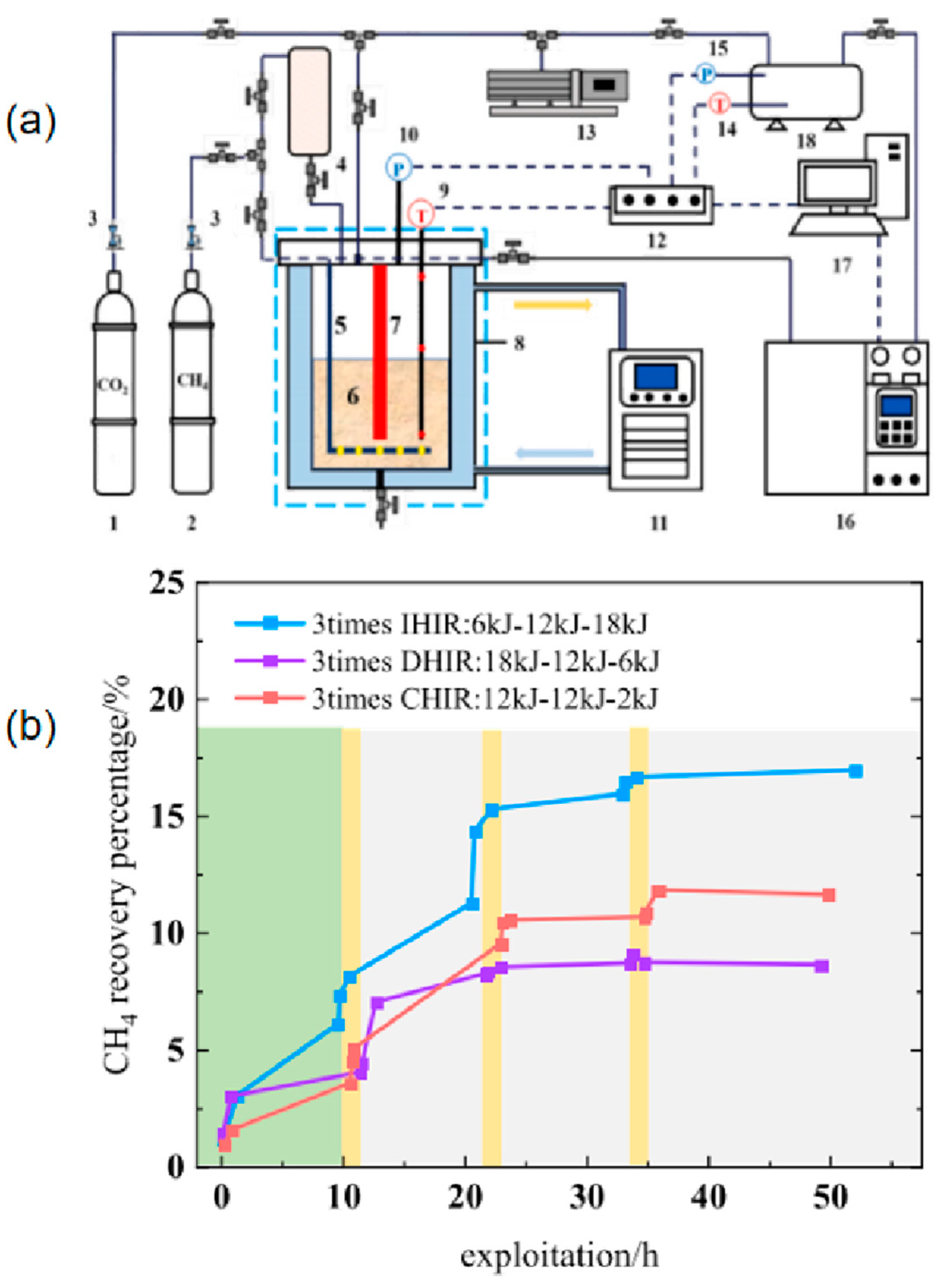
3.2. Combined Extraction of Displacement and Thermal Stimulation Methods

The thermal stimulation method is simple to operate, technically mature, and widely applicable. However, when used alone for natural gas extraction, the thermal stimulation method can be costly and may lead to reservoir instability, potentially triggering geological hazards. Therefore, in practical applications, thermal stimulation is often combined with the displacement method. This combination can improve methane recovery rates while reducing the energy consumption and reservoir instability risks associated with thermal stimulation [61,62].
Zhang et al. [62] studied the CH4 substitution rate from the perspective of combined thermal stimulation and displacement methods for natural gas extraction. They found that the methane recovery efficiency (CRE) during the hydrate substitution process significantly increased from the original 10–50% to 21–63%. Tupsakhare et al. [63] conducted heating stimulation experiments using a gas mixture of 85% CO2 and 15% N2 with heating powers of 100 W, 50 W, and 20 W. Under a 100 W heating power, about 60% of the methane gas could be extracted from the hydrate. In another study, Tupsakhare et al. combined CO2/N2 displacement with thermal stimulation to enhance hydrate recovery. The results showed that, compared to the recovery rate of 26.5% from thermal stimulation alone, the recovery efficiency of natural gas using the combined thermal stimulation and displacement method (68.8%) was significantly higher.
The efficiency of heat transfer varies significantly depending on the choice of heat source. When using an external heat source for hydrate extraction, its efficiency is generally lower than that of internal heat sources. The main reason for this is that heat tends to dissipate in the non-hydrate regions outside the hydrate layer [21]. Fan et al. [64] conducted experiments, as shown in Figure 8a, to explore three different heat injection modes: Incremental Heating Injection for Enhanced Replacement Recovery (IHIR), Decremental Heating Injection for Enhanced Replacement Recovery (DHIR), and Constant Heating Injection for Enhanced Replacement Recovery (CHIR). The changes in CH4 recovery rates under these modes are presented in Figure 8b. The results show that incremental heat injection can lead to more CH4 dissociation and replacement, achieving the highest CH4 recovery rate (17.0%) and the highest gas mole fraction (13.5%) while also reducing the energy consumption for gas separation and purification.
The combined use of thermal stimulation and displacement methods can play a crucial role in enhancing CH4 recovery and CO2 sequestration. However, ensuring the stability and safety of the operation through effective monitoring and adjustments remains a challenge for technical implementation. Additionally, in practical applications, optimizing the parameters of thermal stimulation and displacement to balance methane recovery and CO2 sequestration is still an important area of research.

3.3. Combined Extraction of Displacement and Chemical Inhibitor Methods

The chemical inhibitor method has the advantages of accelerating the decomposition of natural gas hydrates and improving methane recovery efficiency. However, its drawbacks cannot be overlooked. The main issues include poor selectivity of the inhibitors, environmental pollution risks, high costs, and potential adverse effects on the formation and stability of hydrates, which is why it is rarely used alone in natural gas hydrate extraction. In recent years, some researchers have combined chemical additives with the CO2-CH4 hydrate displacement method to explore joint extraction technologies. Tetra-n-butylammonium bromide (TBAB), a commonly used hydrate promoter, has been applied to enhance CO2-CH4 displacement research. It effectively lowers the phase equilibrium conditions of CO2 hydrate, thereby improving the displacement capacity of CO2 for CH4 hydrate and significantly enhancing the displacement efficiency [65]. Some studies also indicate that [66] chemical inhibitors can effectively improve CO2’s displacement efficiency for CH4 hydrate, optimizing the extraction process. However, simultaneous decomposition and displacement significantly reduce displacement efficiency. Therefore, the optimal approach is to first add chemical inhibitors to decompose CH4 hydrate, releasing most of the CH4 gas, and then inject CO2 for displacement, which can significantly improve displacement efficiency. In addition to thermodynamic inhibitors, researchers have also explored hydrate promoters and anti-agglomerants. Heydari and Peyvandi’s study [67], which used biological surfactants to replace natural gas hydrates, showed that biological surfactants not only effectively promoted the formation of methane hydrates but also significantly improved CO2 displacement efficiency. Specifically, the displacement ratio increased by 72.6%, and displacement kinetics improved by 39%. Although the biological surfactants were added during the hydrate formation phase, the study also indicated that their addition altered the hydrate morphology and had a positive impact on continuous displacement reactions.
Currently, this method is still in the early stages of research, with many scholars, both domestically and internationally, conducting related studies. The displacement potential and economic benefits remain unclear. In addition, issues such as the selection and optimization of inhibitors, environmental impacts, and their long-term effectiveness and stability continue to be major constraints for large-scale applications. Therefore, how to better simulate and understand these coupled processes, optimize process parameters, and achieve the best extraction results remains a significant challenge in technological progress.
Overall, the combined application of the displacement method and traditional extraction methods provides an innovative solution for natural gas extraction. This combination not only significantly optimizes extraction efficiency but also provides strong support for the sustainable development of energy. As shown in Table 5, the combination of the displacement method with three traditional methods demonstrates complementary advantages in several aspects, further enhancing the overall extraction efficiency.
The combination of CO2 injection, depressurization, thermal stimulation, and chemical inhibitors has shown significant potential in natural gas hydrate extraction, improving recovery rates (such as sustained methane production in the South China Sea pilot project) and carbon sequestration efficiency, contributing to the low-carbon transition. However, its technical depth and scaling face multiple challenges: the CO2 injection and depressurization combination is limited by reservoir permeability differences, with low-permeability gas fields prone to insufficient fluidity and potential underground water contamination risks; combined with thermal stimulation, although it enhances gas flow (as seen in the Russia Mezoyakha gas field), the high-temperature environment accelerates equipment aging, increases maintenance costs, and irreversible changes in reservoir porosity threaten long-term stability [1]; when used with chemical inhibitors (such as ethylene glycol), although it can control hydrate dissociation risks (as seen in the South China Sea basin project in Japan), long-term use poses underground water contamination risks and relies on costly monitoring systems. On the economic side, high initial investments (equipment and reservoir modification) and specialized operation and maintenance costs far exceed the financial capacity of small and medium-sized enterprises, while the imperfect carbon trading market and fragmented policies further weaken revenue stability. Despite significant technical advantages, the large-scale application still needs to overcome core challenges such as geological adaptability, equipment durability, and environmental risks. In the future, AI should be used to optimize technical parameters, low-cost materials should be developed, and a global carbon market should be promoted, along with tax incentives and international standards coordination at the policy level, to balance energy efficiency and climate goals [4].

4. Multicomponent Gas Displacement Process

The CO2-CH4 hydrate replacement has become a widely studied field in academia. Previous studies have shown that up to 68% of the methane (CH4) captured in hydrates can be replaced by carbon dioxide (CO2) for recovery [20,70]. The main reasons for the low efficiency of CO2 replacement in natural gas hydrate extraction are as follows: (1) The methane (CH4) molecules in natural gas hydrates are relatively small and can be accommodated in the “large cages” and “small cages” of the hydrate structure. In contrast, CO2 molecules, which are slightly larger and have a different molecular structure compared to CH4, can only replace methane molecules in the large cages and are unable to effectively replace methane in the small cages. (2) There are strong van der Waals forces between methane molecules and hydrate cages, which makes the methane molecules tightly bound within the hydrate. (3) During the CO2 replacement process, when CO2 molecules enter the hydrate structure, especially at the hydrate surface, CO2 forms a mixed hydrate layer with some methane molecules. This leads to difficulty in CO2 entering the internal structure of the hydrate, limiting the exchange between CO2 and methane and significantly reducing the replacement efficiency. Therefore, finding small molecular gases that can replace CH4 in the small cages, increasing the hydrate phase equilibrium pressure, and enhancing gas transfer are key factors in improving the efficiency of CO2 replacement for natural gas hydrate extraction.

4.1. CO2-H2 Mixture Replacement to Improve CH4 Recovery Rate

The use of a CO2 and H2 mixture can improve the replacement efficiency [28]. The addition of H2 does not lead to additional occupation of the hydrate cages. The reason hydrogen can facilitate the replacement process is primarily because H2 molecules, being smaller, diffuse easily within the hydrate system. The introduction of H2 reduces the partial pressure of methane in the gas phase, which helps to destabilize the methane hydrate, promoting its dissociation rather than directly replacing methane through gas exchange. Additionally, H2 can enhance the mass transfer process, aiding in the diffusion of methane gas within the medium [71]. The CO2-H2 methane extraction technology uses mixed gas injection to enhance recovery and carbon sequestration. CO2 displaces methane, while H2 boosts reservoir permeability [28]. Benefits include hydrogen’s high diffusivity for improved gas flow and catalytic carbon utilization (e.g., methane dry reforming). Key challenges include the following: hydrogen flammability risks, complex gas separation (membrane/cryogenic methods), and hydrogen embrittlement under high pressure. No large-scale applications exist yet, with insights drawn from hydrogen storage and CO2-EOR. Heterogeneous reservoirs risk uneven gas distribution and efficiency drops. High costs dominate, alongside safety expenses and uncertain carbon revenue. Future success hinges on affordable green hydrogen, hydrogen-resistant materials, and integrated “production-extraction-sequestration” systems to balance feasibility and economics in low-carbon transitions.
This finding aligns with the research by Ding et al. [27], who used a simulated CO2/H2 mixed gas integrated gasification combined cycle (IGCC) to replace CH4 in methane hydrates and monitored the changes in CH4, CO2, and H2 gas concentrations using a gas chromatograph (GC). Three key points (hydrate phase “A” point, gas–hydrate interface “B” point, and gas phase “C” point) were selected for Raman detection (as shown in Figure 9). As shown in Figure 9a, the experiment formed sI CH4 hydrate. During the continuous injection of the CO2/H2 gas mixture into the reactor, the Raman spectra changes at the hydrate phase point (Figure 9c,d) indicated the formation of CO2 and CH4 hydrates, suggesting that the replacement occurs only between CO2 and CH4 molecules. No H2 signal was detected in the figures, as shown in Figure 9b, indicating that H2 was not encapsulated in the hydrate cages. The experiment demonstrated that the replacement process occurs in two steps: first, the dissociation of CH4 hydrate, followed by the formation of CO2 hydrate. Furthermore, the CH4 recovery rate through CH4-CO2/H2 replacement was greater than 71%, significantly higher than the CH4-CO2 replacement (50%). Notably, H2 does not compete with CH4 for occupying hydrate cages but rather plays a facilitative role in the CO2-CH4 replacement process.
Figure 10a shows the phase equilibrium conditions of hydrates formed by mixtures of H2 + CH4 + CO2 at different ratios. The injection ratio of H2 has a significant impact on the phase equilibrium of the H2 + CH4 + CO2 ternary hydrate. As the H2 ratio increases, the dissociation kinetics of the hydrate become more favorable, but the separation barrier for CO2 also increases. In contrast, a lower H2 ratio favors the formation of the hydrate but may lead to a lower CH4 yield [72].
The study by Sun et al. [73] shows that when the mole fraction of CO2 in the gas is low, the impact of the mixed gas on the hydrate structure is more significant. Additionally, as the hydrogen content increases, the dissociation rate of CH4 hydrates also shows an increasing trend. Under appropriate temperature and pressure conditions, the methane replacement rate can reach over 90% [74]. Wang et al. [28] conducted experiments with different gas compositions (mole ratios of CO2 and H2), during which they monitored parameters such as the mole ratio of CO2 and H2 during the gas exchange process, methane replacement rate, and CO2 sequestration ratio. The study indicates that there is a balance point between the mole fractions of CO2 and H2: too high a mole fraction of CO2 promotes CO2 sequestration but sacrifices gas yield, while a higher mole fraction of H2 favors gas yield but is not conducive to CO2 sequestration. A balance in CO2 substitution can be achieved within a CO2 mole fraction range of 55% to 72%, as shown in Figure 10b. Xu et al. [75] conducted replacement experiments under specific temperature and pressure conditions and analyzed the composition of released gases using gas chromatography (GC), measuring the CH4 replacement efficiency during the process. The results show that there are significant differences in the final composition and replacement efficiency of CH4 in experiments with different gas mixtures. The order of replacement efficiency is as follows: CO2/H2 > CO2/N2 > pure CO2. Xie et al. [76] clarified the impact of gas partial pressure on hydrate replacement in CH4-rich systems. The experimental results, for the first time, show that in a CO2/CH4/H2 ternary gas system, even if the partial pressure of CH4 exceeds the phase equilibrium pressure of CH4 hydrates, H2 can promote the premature dissociation of CH4 hydrates. The effects of different H2 and CO2 gas mixing ratios on the extraction efficiency of pure hydrate phases and hydrate-sediment mixed phases are detailed in Table 6.

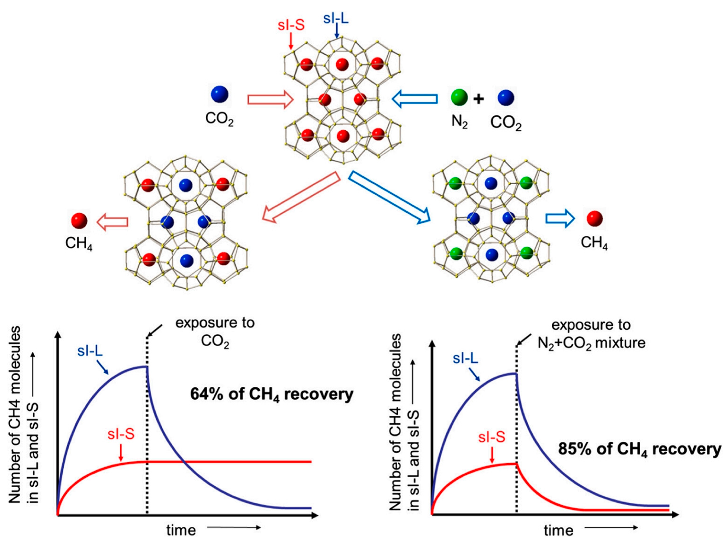
4.2. CO2 and N2 Mixture Displacement to Improve CH4 Recovery Rate

The application of CO2 and N2 mixed gas displacement in methane (CH4) extraction is considered an effective method to significantly improve the methane recovery rate from natural gas hydrates. The CO2 and nitrogen gas mixed methane extraction technology involves the simultaneous injection of CO2 and N2, which work synergistically to displace adsorbed methane and reduce pressure, achieving both enhanced recovery and carbon sequestration. Its advantage lies in the ability to adjust the gas mixture ratio to suit geological conditions (such as permeability and temperature) while reducing the risk of secondary hydrate formation. However, there are significant technical challenges: the gas mixture ratio needs precise control to avoid pore blockage or decreased efficiency, adsorption separation technologies (such as pressure swing adsorption) have limited adaptability to complex formations, and high-pressure corrosive environments exacerbate equipment wear and increase maintenance costs. In practical applications, while experiences from CO2-enhanced oil recovery (such as Shengli Oilfield) and nitrogen-assisted extraction can be referenced, large-scale cases remain scarce, and heterogeneous formations are prone to gas retention or micro-seismic risks. Economically, the high initial investment and operational energy consumption depend on carbon trading revenues. However, small and medium-sized enterprises face challenges due to financial pressure and fragmented policies, especially in regions with underdeveloped carbon markets. Future progress will require technological optimization (such as AI control and low-cost catalysts), policy coordination (global carbon pricing), and industry chain integration (gas fields—chemicals—sequestration) to help balance resource development and emission reduction goals in the energy transition. Research by Park et al. [25] shows that when flue gas is used to replace methane (CH4) in Type I hydrates, the displacement efficiency can reach 85%, while the displacement efficiency of pure CO2 gas is only 64%. Raman spectroscopy results indicate that approximately 23% of CH4 in the hydrate cages is replaced by N2, while 62% is replaced by CO2. This suggests that CH4 can be displaced by N2, and the occupation of N2 effectively improves the replacement efficiency. Koh et al. [42] summarized that N2, as a smaller guest molecule, can form type II hydrates on its own. Different concentrations of mixed gases, pure CO2, and N2 lead to the formation of different Type I and Type II hydrate structures. Since CO2 molecules are larger, the addition of N2 gas can significantly improve the displacement efficiency (as shown in Figure 11). When pure CO2 gas is used to replace methane in hydrates, CO2 molecules are thermodynamically unstable in the small Type I cages (512). Therefore, displacement mainly occurs in the larger Type I cages (51262), and methane molecules in the small cages are not replaced.
After the introduction of N2, N2, as a smaller molecule, tends to occupy the small cages, which allows N2 and CO2 to work together to achieve the displacement process in both large and small cages. This interaction not only enhances methane recovery but also effectively improves production efficiency [77]. Research by Pandey et al. [78] also indicates that the use of a CO2 and N2 mixed gas can further increase methane recovery. Furthermore, as the concentration of CO2 in the CO2 + N2 mixture increases, the methane recovery rate also rises, while the stability of the mixed CH4-CO2 hydrate is enhanced.
Specifically, the essential mechanism of this process lies in the competition between N2 and CO2 gases for entry into the molecular cage structures of the hydrate. Due to the different molecular behaviors of N2 and CO2 during hydrate formation, N2 gas can influence the dissolution of CO2 and the conditions for hydrate formation. When N2 competes with CO2 for entry into the hydrate cages, it alters the thermodynamic stability of the hydrate, making the temperature and pressure conditions for hydrate formation more stringent than those for pure CO2 hydrates.
Various researchers have conducted studies on the impact of different CO2 and N2 mixing ratios on methane (CH4) hydrate recovery rates, and the results are shown in Table 7. Lee et al. [79] primarily used Differential Scanning Calorimetry (DSC) and Pressure–Volume–Temperature (PVT) experimental methods to investigate the replacement process of methane hydrate (CH4·nH2O) under different gas mixing systems, particularly the displacement process with CO2 and N2 mixed gases. The study found that the injection of mixed gases effectively promotes the dissociation of methane hydrates, enabling methane recovery while also trapping CO2 as CO2 hydrates or mixed hydrates. Additionally, the gas mixture ratio significantly influences the displacement efficiency, with different gas combinations exhibiting varying replacement effects. During the displacement process, the original pure methane hydrate gradually transforms into a mixed hydrate composed of CH4, CO2, and N2. This change leads to increased fluctuations in heat flow, thereby affecting the thermodynamic and kinetic properties of the hydrate.
In a CO2 and N2 mixed gas environment, when the nitrogen (N2) proportion is relatively low, the methane (CH4) displacement recovery rate is very low. However, when the N2 proportion exceeds 50%, the methane displacement recovery rate increases to 12.2%, while the CO2 hydrate sequestration rate reaches 42.8%. In contrast, when pure liquid CO2 is used for natural gas hydrate extraction, the CO2 sequestration rate is only 22.1%, significantly lower than the effectiveness of the CO2 and N2 mixed gas displacement method [59,75,79,80,81].
Experimental results and the equilibrium pressure data of the hydrate at different N2 ratios (as shown in Figure 12) indicate that when CO2 and N2 mixed gases are used for natural gas hydrate extraction, the equilibrium pressure of the hydrate increases with the increase in the N2 proportion. At higher N2 concentrations, the hydrate requires higher pressure to maintain its stability. The stability of CH4 hydrate decreases, making it more prone to replacement reactions, and the recovery rate significantly improves [72].
Since sI hydrates are widely present in natural gas hydrates, most studies focus on the replacement reactions in sI hydrates. However, sII hydrates have also been found in nature in certain regions, and the replacement mechanism of sII hydrates is significantly different from that of sI hydrates. Seo et al. promoted the replacement reaction of sII (C3H8 + CH4) hydrate by externally injecting a CO2/N2 (50:50) mixed gas. The study showed that the replacement degree of C3H8 + CH4 hydrate was about 54%. This method not only achieved a higher gas recovery rate than the pure CO2 replacement method but also maintained the crystal structure of the hydrate after the replacement reaction (as shown in Figure 13b), indicating that the replacement process did not cause any structural changes in the sII hydrate. At the same time, according to the Raman spectrum of the CO2 and N2 molecular vibration modes in the C3H8 + CH4 hydrate (Figure 13a), it was observed that both CO2 and N2 molecules occupied the cages of the sII hydrate. In Figure 13c, the reduction in C3H8 and CH4 amounts in the initial C3H8 + CH4 hydrate and the increase in CO2 and N2 amounts in the replaced C3H8 + CH4 hydrate are similar, further confirming that CH4 in the small cages is replaced by N2, while C3H8 in the large cages is mainly replaced by CO2 [82].
Overall, although a higher proportion of N2 helps improve the displacement efficiency and CO2 sequestration rate, it also introduces new challenges, such as the formation of multiple hydrates and the encapsulation effect, which may adversely affect the methane displacement recovery rate. Therefore, when using mixed gas displacement methods for natural gas hydrate extraction, it is necessary to comprehensively consider factors such as gas ratios, displacement efficiency, and the formation and encapsulation effects of hydrates to achieve optimal recovery and CO2 sequestration outcomes.

4.3. The Displacement of CH4 Recovery Is Improved by Using CO2 Mixed with N2 and H2

When using a CO2 and N2 mixed gas for natural gas hydrate displacement, it can promote the dissociation of hydrates under lower pressure conditions, theoretically improving gas displacement efficiency. However, in practical operations, the displacement effect of the mixed gas has not fully achieved the expected recovery rate, indicating that some factors during the actual dissociation process may have affected the enhancement of displacement efficiency.
The main reason for this phenomenon is that the formation of CO2 hydrates and N2 hydrates adversely affects the recovery of internal natural gas hydrates, primarily methane hydrates. Specifically, CO2 and N2 interact with the hydrate structure during the displacement process, forming CO2 hydrates and N2 hydrates. These newly formed hydrate structures can encapsulate the original methane hydrate particles, hindering their dissociation and release, thus impacting the methane recovery efficiency [29].
Therefore, under different pressure and temperature conditions, Chaturvedi et al. [83] studied the effects of CO2, N2, and H2 combinations on hydrate formation and methane recovery. At higher N2 concentrations, even with the introduction of a small amount of H2, the methane recovery rate in natural gas hydrates could still be increased to 67–69 mol% (Figure 14a–c). When the H2 concentration increased from 0.1 mol% to 1 mol%, the methane recovery rate further improved to 71 mol%, and the presence of hydrogen at high pressure promoted natural gas hydrate formation. Previous studies have paid less attention to the synergistic effect of H2 in the presence of N2, and a possible explanation has been proposed: small gas molecules like N2 occupy smaller hydrate cages, preventing CO2 from entering larger cages and thus hindering hydrate formation. However, H2 competes with N2 for the smaller cages, allowing CO2 to fill the larger cages for a longer time until the hydrate channels close. This theory, however, still requires further verification. Although the hydrogen promoter increased the hydrate yield and expanded the hydrate formation region, its effect remained limited at high N2 concentrations. Further research indicated that when the H2 mol% exceeded 1 mol%, the methane recovery rate no longer increased significantly (Figure 14d–g), possibly because H2 occupies hydrate cages, hindering further natural gas hydrate formation.
The mechanism can be further illustrated in Figure 15. The addition of hydrogen helps optimize the hydrate formation process of the CO2 + N2 mixed gas, and H2 helps increase the rate of hydrate formation, thereby accelerating CO2 storage and conversion and optimizing the gas displacement effect for methane. However, if the hydrogen concentration is excessively high, it could disrupt the stability of CO2 hydrates. Elevated hydrogen levels may compete with CO2 for hydrate formation, thereby hindering the formation of CO2 hydrates and diminishing its ability to replace methane effectively. Moreover, hydrogen itself does not have a strong ability to form hydrates, and its hydrate formation rate is much lower than that of CO2, and excessively high hydrogen concentrations may lead to adverse changes in the structure and thermodynamic properties of the hydrates, affecting the overall stability of the reservoir. Therefore, to ensure reservoir stability and maximize methane recovery, it is essential to strictly control the hydrogen proportion when injecting CO2 + N2 + H2 mixed gas [27].

5. Conclusions

Displacement reactions, as an important method for the production and storage of multi-component gases from hydrates, have made significant progress in basic research and laboratory stages, demonstrating their broad application potential in areas such as energy storage, gas separation, and environmental protection. Storing gases in hydrates not only significantly increases the gas storage density but also enables efficient gas release and reuse under low-temperature and normal-pressure conditions.
However, despite some success in laboratory studies of hydrate displacement reactions, several challenges remain in practical applications. First, the efficiency and reaction rate of the displacement reaction are still limited, and the thermodynamic issues and optimization of reaction conditions need further research. Second, the selective displacement and stability of multi-component gases need to be addressed through additional theoretical and experimental work.
To further improve the technical efficiency of methane displacement with mixed gases and achieve sustainable development, the following research directions need to be explored:
Improving the accuracy of experimental devices and numerical models: Future work should focus on developing more accurate experimental equipment and numerical models that are closer to real extraction environments, validating the performance and effectiveness of different gas mixtures.
In-depth study of the internal mechanisms of the displacement process: Future research should use high-resolution experiments and theoretical simulations to clarify the thermodynamic and kinetic characteristics of different reaction paths, providing a theoretical basis for optimizing displacement efficiency.
Optimizing the gas mixture ratio and injection strategy: For the injection of CO2, N2, and H2 mixed gases, optimizing the ratio and injection strategy to achieve the best methane recovery rate and CO2 storage efficiency is a key area for future research. Additionally, the synergistic effects of salt additives and gases should be considered, exploring the combined impact of CO2+N2+salt additives on reservoir stability, recovery rate, and CO2 sequestration efficiency.
Improving CO2 sequestration and stability: Future research should focus on the long-term safety of CO2 sequestration, the storage capacity of reservoirs, and potential leakage pathways to ensure the environmental safety of the technology.
Enhancing the dual utilization benefits of CO2 and methane: Combining the extraction of CO2 and CH4 hydrates with long-term CO2 sequestration through integrated energy recovery and greenhouse gas emission reduction measures can enhance the overall benefits of natural gas hydrate extraction. The secondary sequestration method combining high-temperature CO2 with deep geothermal energy can improve CO2 sequestration rates while potentially enhancing methane recovery, promoting the development of this technology in a green and energy-efficient direction.

Author Contributions

Z.Z.: data reduction and writing and editing; X.Z.: methodology and review and editing. S.W.: conceptualization and data analysis; L.J.: literature investigation and summary; H.D.: review and revision. P.L.: methodology, resources, supervision, and editing. All authors have read and agreed to the published version of the manuscript.

Funding

This study was supported by the National Natural Science Foundation of China (Grant No. 52376175, 52106213), Shanxi Scholarship Council of China (2024-115), and Key Talent Team for Science and Technology Innovation in Shanxi Province (202204051002023).

Conflicts of Interest

The authors declare no conflicts of interest.

References

  1. Yu, Y.-S.; Zhang, X.; Liu, J.-W.; Lee, Y.; Li, X.S. Natural gas hydrate resources and hydrate technologies: A review and analysis of the associated energy and global warming challenges. Energy Environ. Sci. 2021, 14, 5611–5668. [Google Scholar] [CrossRef]
  2. Musakaev, N.; Khasanov, M.; Borodin, S.L. The mathematical model of the gas hydrate deposit development in permafrost. Int. J. Heat Mass Transf. 2018, 118, 455–461. [Google Scholar] [CrossRef]
  3. Wei, N.; Pei, J.; Li, H.; Zhou, S.; Zhao, J.; Kvamme, B.; Coffin, R.B.; Zhang, L.; Zhang, Y.; Xue, J.; et al. Classification of natural gas hydrate resources: Review, application and prospect. Gas Sci. Eng. 2024, 124, 205269. [Google Scholar] [CrossRef]
  4. Ma, K.; Li, D.; Liang, D. Reservoir stimulation technologies for natural gas hydrate: Research progress, challenges, and perspectives. Energy Fuels. 2023, 37, 10112–10133. [Google Scholar] [CrossRef]
  5. Makogon, Y.F. Natural gas hydrates—A promising source of energy. J. Nat. Gas Sci. Eng. 2010, 2, 49–59. [Google Scholar] [CrossRef]
  6. Sun, H.; Chen, B.; Zhu, Z.; Zhang, L.; Yang, M.; Song, Y. Research development in the traditional methods and water flow erosion for natural gas hydrate production: A review. Energy Technol. 2023, 11, 2201011. [Google Scholar] [CrossRef]
  7. Ji, C.; Ahmadi, G.; Smith, D.H. Natural gas production from hydrate decomposition by depressurization. Chem. Eng. Sci. 2001, 56, 5801–5814. [Google Scholar] [CrossRef]
  8. Fitzgerald, G.C.; Castaldi, M.J. Thermal Stimulation Based Methane Production from Hydrate Bearing Quartz Sediment. Ind. Eng. Chem. Res. 2013, 52, 6571–6581. [Google Scholar] [CrossRef]
  9. Farhadian, A.; Shadloo, A.; Zhao, X.; Pavelyev, R.S.; Peyvandi, K.; Qiu, Z.; Varfolomeev, M.A. Challenges and advantages of using environmentally friendly kinetic gas hydrate inhibitors for flow assurance application: A comprehensive review. Fuel 2023, 336, 127055. [Google Scholar] [CrossRef]
  10. Li, X.-S.; Yang, B.; Zhang, Y.; Li, G.; Duan, L.-P.; Wang, Y.; Chen, Z.-Y.; Huang, N.-S.; Wu, H.-J. Experimental investigation into gas production from methane hydrate in sediment by depressurization in a novel pilot-scale hydrate simulator. Appl. Energy 2012, 93, 722–732. [Google Scholar] [CrossRef]
  11. Zhang, Y.; Li, X.-S.; Chen, Z.-Y.; Wang, Y.; Ruan, X.-K. Effect of Hydrate Saturation on the Methane Hydrate Dissociation by Depressurization in Sediments in a Cubic Hydrate Simulator. Ind. Eng. Chem. Res. 2015, 54, 2627–2637. [Google Scholar] [CrossRef]
  12. Wan, K.; Wang, Y.; Li, X.-S.; Zhang, L.-H.; Meng, T. Pilot-scale experimental study on natural gas hydrate decomposition with innovation depressurization modes. Appl. Energy 2024, 373, 123921. [Google Scholar] [CrossRef]
  13. Cranganu, C. In-situ thermal stimulation of gas hydrates. J. Pet. Sci. Eng. 2009, 65, 76–80. [Google Scholar] [CrossRef]
  14. Yamada, H.; Chen, L.; Lacaille, G.; Shoji, E.; Okajima, J.; Komiya, A.; Maruyama, S. Experimental Study of Methane Hydrate Dissociation and Gas Production Behaviors under Depressurization. Int. J. Mech. Eng. Robot. Res. 2017, 6, 140–146. [Google Scholar] [CrossRef]
  15. Zhao, E.; Hou, J.; Du, Q.; Liu, Y.; Ji, Y.; Bai, Y. Numerical modeling of gas production from methane hydrate deposits using low-frequency electrical heating assisted depressurization method. Fuel 2021, 290, 120075. [Google Scholar] [CrossRef]
  16. Liao, B.; Wang, J.; Sun, J.; Lv, K.; Liu, L.; Wang, Q.; Wang, R.; Lv, X.; Wang, Y.; Chen, Z. Microscopic insights into synergism effect of different hydrate inhibitors on methane hydrate formation: Experiments and molecular dynamics simulations. Fuel 2023, 340, 127488. [Google Scholar] [CrossRef]
  17. Yagasaki, T.; Matsumoto, M.; Tanaka, H. Effects of thermodynamic inhibitors on the dissociation of methane hydrate: A molecular dynamics study. Phys. Chem. Chem. Phys. 2015, 17, 32347–32357. [Google Scholar] [CrossRef]
  18. Wang, P.; Li, Y.; Sun, N.; Han, S.; Wang, X.; Su, Q.; Li, Y.; He, J.; Yu, X.; Du, S. Hydrate technologies for CO2 capture and sequestration: Status and perspectives. Chem. Rev. 2024, 124, 10363–10385. [Google Scholar] [CrossRef]
  19. Yan, P.; Luan, H.; Jiang, Y.; Liang, W.; Liu, M.; Chen, H. Influence of depressurization mode on natural gas hydrate production characteristics: One-dimensional experimental study. Geoenergy Sci. Eng. 2024, 234, 212671. [Google Scholar] [CrossRef]
  20. Lee, H.; Seo, Y.; Seo, Y.T.; Moudrakovski, I.L.; Ripmeester, J.A. Recovering methane from solid methane hydrate with carbon dioxide. Angew. Chem. Vol. 2003, 115, 5202–5205. [Google Scholar] [CrossRef]
  21. Wang, Y.; Lang, X.; Fan, S.; Wang, S.; Yu, C.; Li, G. Review on Enhanced Technology of Natural Gas Hydrate Recovery by Carbon Dioxide Replacement. Energy Fuels 2021, 35, 3659–3674. [Google Scholar] [CrossRef]
  22. Ohgaki, K.; Takano, K.; Sangawa, H.; Matsubara, T.; Nakano, S. Methane exploitation by carbon dioxide from gas hydrates—Phase equilibria for CO2-CH4 mixed hydrate system. J. Chem. Eng. Jpn. 1996, 29, 478–483. [Google Scholar] [CrossRef]
  23. Yezdimer, E.M.; Cummings, P.T.; Chialvo, A.A. Determination of the Gibbs free energy of gas replacement in SI clathrate hydrates by molecular simulation. J. Phys. Chem. A 2002, 106, 7982–7987. [Google Scholar] [CrossRef]
  24. Ota, M.; Abe, Y.; Watanabe, M.; Smith, R.L.; Inomata, H. Methane recovery from methane hydrate using pressurized CO2. Fluid Phase Equilibria 2005, 228–229, 553–559. [Google Scholar] [CrossRef]
  25. Park, Y.; Kim, D.-Y.; Lee, J.-W.; Huh, D.-G.; Park, K.-P.; Lee, J.; Lee, H. Sequestering carbon dioxide into complex structures of naturally occurring gas hydrates. Proc. Natl. Acad. Sci. USA 2006, 103, 12690–12694. [Google Scholar] [CrossRef]
  26. Sloan Jr, E.D.; Koh, C.A. Clathrate Hydrates of Natural Gases; CRC Press: Boca Raton, FL, USA, 2007. [Google Scholar]
  27. Ding, Y.-L.; Xu, C.-G.; Yu, Y.-S.; Li, X.-S. Methane recovery from natural gas hydrate with simulated IGCC syngas. Energy 2017, 120, 192–198. [Google Scholar] [CrossRef]
  28. Wang, X.-H.; Sun, Y.-F.; Wang, Y.-F.; Li, N.; Sun, C.-Y.; Chen, G.-J.; Liu, B.; Yang, L.-Y. Gas production from hydrates by CH4-CO2/H2 replacement. Appl. Energy 2017, 188, 305–314. [Google Scholar] [CrossRef]
  29. Chaturvedi, K.R.; Sinha, A.; Nair, V.C.; Sharma, T. Enhanced carbon dioxide sequestration by direct injection of flue gas doped with hydrogen into hydrate reservoir: Possibility of natural gas production. Energy 2021, 227, 120521. [Google Scholar] [CrossRef]
  30. Wei, W.-N.; Li, B.; Gan, Q.; Li, Y.-L. Research progress of natural gas hydrate exploitation with CO2 replacement: A review. Fuel 2022, 312, 122873. [Google Scholar] [CrossRef]
  31. Arora, A.; Cameotra, S.S.; Balomajumder, C. Techniques for exploitation of gas hydrate (clathrates) an untapped resource of methane gas. Energy Fuels 2015, 7, 108–111. [Google Scholar]
  32. Lo, H.; Lee, M.-T.; Lin, S.-T. Water vacancy driven diffusion in clathrate hydrates: Molecular dynamics simulation study. J. Phys. Chem. C 2017, 121, 8280–8289. [Google Scholar] [CrossRef]
  33. Peters, B.; Zimmermann, N.E.; Beckham, G.T.; Tester, J.W.; Trout, B.L. Path sampling calculation of methane diffusivity in natural gas hydrates from a water-vacancy assisted mechanism. J. Am. Chem. Soc. 2008, 130, 17342–17350. [Google Scholar] [CrossRef] [PubMed]
  34. Schicks, J.M. Thermodynamic properties and phase equilibria characteristics of natural gas hydrates. In Advances in Natural Gas: Formation, Processing, and Applications. Volume 3: Natural Gas Hydrates; Elsevier: Amsterdam, The Netherlands, 2024; pp. 65–86. [Google Scholar]
  35. Anderson, G.K. Enthalpy of dissociation and hydration number of carbon dioxide hydrate from the Clapeyron equation. J. Chem. Thermodyn. 2003, 35, 1171–1183. [Google Scholar] [CrossRef]
  36. Ma, Z.W.; Zhang, P.; Bao, H.S.; Deng, S. Review of fundamental properties of CO2 hydrates and CO2 capture and separation using hydration method. Renew. Sustain. Energy Rev. 2016, 53, 1273–1302. [Google Scholar] [CrossRef]
  37. Hachikubo, A.; Miura, T.; Yamada, K.; Sakagami, H.; Takahashi, N.; Hyakutake, K.; Abe, K.; Shoji, H. Phase equilibrium and comparison of formation speeds of CH4 and CO2 hydrate below the ice point. In Proceedings of the 5th International Conference on Gas Hydrates, Trondheim, Norway, 13–16 June 2005. [Google Scholar]
  38. Goel, N. In situ methane hydrate dissociation with carbon dioxide sequestration: Current knowledge and issues. J. Pet. Sci. Eng. 2006, 51, 169–184. [Google Scholar] [CrossRef]
  39. Circone, S.; Stern, L.A.; Kirby, S.H.; Durham, W.B.; Chakoumakos, B.C.; Rawn, C.J.; Rondinone, A.J.; Ishii, Y. CO2 hydrate: Synthesis, composition, structure, dissociation behavior, and a comparison to structure I CH4 hydrate. J. Phys. Chem. B 2003, 107, 5529–5539. [Google Scholar] [CrossRef]
  40. Xie, W.; Wang, H.; Vandeginste, V.; Chen, S.; Gan, H.; Wang, M.; Yu, Z. Thermodynamic and kinetic affinity of CO2 relative to CH4 and their pressure, temperature and pore structure sensitivity in the competitive adsorption system in shale gas reservoirs. Energy 2023, 277, 127591. [Google Scholar] [CrossRef]
  41. Yin, Z.; Khurana, M.; Tan, H.K.; Linga, P. A review of gas hydrate growth kinetic models. Chem. Eng. J. 2018, 342, 9–29. [Google Scholar] [CrossRef]
  42. Koh, D.-Y.; Kang, H.; Lee, J.-W.; Park, Y.; Kim, S.-J.; Lee, J.; Lee, J.Y.; Lee, H. Energy-efficient natural gas hydrate production using gas exchange. Appl. Energy 2016, 162, 114–130. [Google Scholar] [CrossRef]
  43. Sloan, E.; Koh, C.A. Estimation techniques for phase Equilibria of natural gas hydrates. In Clathrate Hydrates of Natural Gases; Taylor & Francis Group: London, UK, 2008; pp. 320–523. [Google Scholar]
  44. Zhao, J.; Xu, K.; Song, Y.; Liu, W.; Lam, W.; Liu, Y.; Xue, K.; Zhu, Y.; Yu, X.; Li, Q. A Review on Research on Replacement of CH4 in Natural Gas Hydrates by Use of CO2. Energies 2012, 5, 399–419. [Google Scholar] [CrossRef]
  45. Speight, J.G. Natural Gas: A Basic Handbook; Gulf Professional Publishing: Houston, TX, USA, 2018. [Google Scholar]
  46. Liu, T.; Wu, P.; Chen, Z.; Li, Y. Review on carbon dioxide replacement of natural gas hydrate: Research progress and perspectives. Energy Fuels 2022, 36, 7321–7336. [Google Scholar] [CrossRef]
  47. Ota, M.; Morohashi, K.; Abe, Y.; Watanabe, M.; Smith Jr, R.L.; Inomata, H. Replacement of CH4 in the hydrate by use of liquid CO2. Energy Convers. Manag. 2005, 46, 1680–1691. [Google Scholar] [CrossRef]
  48. Bai, D.; Zhang, X.; Chen, G.; Wang, W. Replacement mechanism of methane hydrate with carbon dioxide from microsecond molecular dynamics simulations. Energy Environ. Sci. 2012, 5, 7033–7041. [Google Scholar] [CrossRef]
  49. Nakano, S.; Moritoki, M.; Ohgaki, K. High-pressure phase equilibrium and Raman microprobe spectroscopic studies on the CO2 hydrate system. J. Chem. Eng. Data 1998, 43, 807–810. [Google Scholar] [CrossRef]
  50. Tung, Y.-T.; Chen, L.-J.; Chen, Y.-P.; Lin, S.-T. Growth of structure I carbon dioxide hydrate from molecular dynamics simulations. J. Phys. Chem. C 2011, 115, 7504–7515. [Google Scholar] [CrossRef]
  51. Cao, X.; Wang, H.; Yang, K.; Wu, S.; Chen, Q.; Bian, J. Hydrate-based CO2 sequestration technology: Feasibilities, mechanisms, influencing factors, and applications. J. Pet. Sci. Eng. 2022, 219, 111121. [Google Scholar] [CrossRef]
  52. Uchida, T.; Ikeda, I.Y.; Takeya, S.; Kamata, Y.; Ohmura, R.; Nagao, J.; Zatsepina, O.Y.; Buffett, B.A. Kinetics and stability of CH4–CO2 mixed gas hydrates during formation and long-term storage. ChemPhysChem 2005, 6, 646–654. [Google Scholar] [CrossRef] [PubMed]
  53. Kuang, Y.; Zhang, L.; Zheng, Y. Enhanced CO2 sequestration based on hydrate technology with pressure oscillation in porous medium using NMR. Energy 2022, 252, 124082. [Google Scholar] [CrossRef]
  54. Farahani, M.V.; Guo, X.; Zhang, L.; Yang, M.; Hassanpouryouzband, A.; Zhao, J.; Yang, J.; Song, Y.; Tohidi, B. Effect of thermal formation/dissociation cycles on the kinetics of formation and pore-scale distribution of methane hydrates in porous media: A magnetic resonance imaging study. Sust. Energy Fuels 2021, 5, 1567–1583. [Google Scholar] [CrossRef]
  55. Wallmann, K.; Riedel, M.; Hong, W.; Patton, H.; Hubbard, A.; Pape, T.; Hsu, C.; Schmidt, C.; Johnson, J.; Torres, M. Gas hydrate dissociation off Svalbard induced by isostatic rebound rather than global warming. Nat. Commun. 2018, 9, 83. [Google Scholar] [CrossRef]
  56. Zhao, J.; Chen, X.; Song, Y.; Zhu, Z.; Yang, L.; Tian, Y.; Wang, J.; Yang, M.; Zhang, Y. Experimental study on a novel way of methane hydrates recovery: Combining CO2 replacement and depressurization. Energy Procedia 2014, 61, 75–79. [Google Scholar] [CrossRef]
  57. Lee, Y.; Deusner, C.; Kossel, E.; Choi, W.; Seo, Y.; Haeckel, M. Influence of CH4 hydrate exploitation using depressurization and replacement methods on mechanical strength of hydrate-bearing sediment. Appl. Energy 2020, 277, 115569. [Google Scholar] [CrossRef]
  58. Chen, Y.; Gao, Y.; Chen, L.; Wang, X.; Liu, K.; Sun, B. Experimental investigation of the behavior of methane gas hydrates during depressurization-assisted CO2 replacement. J. Nat. Gas Sci. Eng. 2019, 61, 284–292. [Google Scholar] [CrossRef]
  59. Yang, J.; Okwananke, A.; Tohidi, B.; Chuvilin, E.; Maerle, K.; Istomin, V.; Bukhanov, B.; Cheremisin, A. Flue gas injection into gas hydrate reservoirs for methane recovery and carbon dioxide sequestration. Energy Convers. Manag. 2017, 136, 431–438. [Google Scholar] [CrossRef]
  60. Sun, Y.; Zhang, G.; Li, S.; Jiang, S. CO2/N2 injection into CH4 + C3H8 hydrates for gas recovery and CO2 sequestration. Chem. Eng. J. 2019, 375, 121973. [Google Scholar] [CrossRef]
  61. Defu, M.; Yingxia, Q.I. Experimental study on the replacement of methane hydrate by CO2 with thermal excitation. Energy 2017, 33, 13–18. [Google Scholar]
  62. Zhang, L.; Yang, L.; Wang, J.; Zhao, J.; Dong, H.; Yang, M.; Liu, Y.; Song, Y. Enhanced CH4 recovery and CO2 storage via thermal stimulation in the CH4/CO2 replacement of methane hydrate. Chem. Eng. J. 2017, 308, 40–49. [Google Scholar] [CrossRef]
  63. Tupsakhare, S.S.; Castaldi, M.J. Efficiency enhancements in methane recovery from natural gas hydrates using injection of CO2/N2 gas mixture simulating in-situ combustion. Appl. Energy 2019, 236, 825–836. [Google Scholar] [CrossRef]
  64. Fan, S.; Yu, W.; Yu, C.; Wang, Y.; Lang, X.; Wang, S.; Li, G.; Huang, H. Investigation of enhanced exploitation of natural gas hydrate and CO2 sequestration combined gradual heat stimulation with CO2 replacement in sediments. J. Nat. Gas Sci. Eng. 2022, 104, 104686. [Google Scholar] [CrossRef]
  65. Mohammadi, A.H.; Eslamimanesh, A.; Richon, D. Semi-clathrate hydrate phase equilibrium measurements for the CO2+H2/CH4+tetra-n-butylammonium bromide aqueous solution system. Chem. Eng. Sci. 2013, 94, 284–290. [Google Scholar] [CrossRef]
  66. Khlebnikov, V.; Antonov, S.; Mishin, A.; Bakulin, D.; Khamidullina, I.; Liang, M.; Vinokurov, V.; Gushchin, P.A. A new method for the replacement of CH4 with CO2 in natural gas hydrate production. Nat. Gas Ind. B 2016, 3, 445–451. [Google Scholar] [CrossRef]
  67. Heydari, A.; Peyvandi, K. Study of biosurfactant effects on methane recovery from gas hydrate by CO2 replacement and depressurization. Fuel 2020, 272, 117681. [Google Scholar] [CrossRef]
  68. Choi, W.; Mok, J.; Lee, J.; Lee, Y.; Lee, J.; Sum, A.K.; Seo, Y. Effective CH4 production and novel CO2 storage through depressurization-assisted replacement in natural gas hydrate-bearing sediment. Appl. Energy 2022, 326, 119971. [Google Scholar] [CrossRef]
  69. Adibi, N.; Mohammadi, M.; Ehsani, M.R.; Khanmohammadian, E. Experimental investigation of using combined CH4/CO2 replacement and thermal stimulation methods for methane production from gas hydrate in the presence of SiO2 and ZnO nanoparticles. J. Nat. Gas Sci. Eng. 2020, 84, 103690. [Google Scholar] [CrossRef]
  70. Lee, S.; Lee, Y.; Lee, J.; Lee, H.; Seo, Y. Experimental verification of methane–carbon dioxide replacement in natural gas hydrates using a differential scanning calorimeter. Environ. Sci. Technol. 2013, 47, 13184–13190. [Google Scholar] [CrossRef]
  71. Sun, Y.-F.; Wang, Y.-F.; Zhong, J.-R.; Li, W.-Z.; Li, R.; Cao, B.-J.; Kan, J.-Y.; Sun, C.-Y.; Chen, G.-J. Gas hydrate exploitation using CO2/H2 mixture gas by semi-continuous injection-production mode. Appl. Energy 2019, 240, 215–225. [Google Scholar] [CrossRef]
  72. Zhang, X.; Zhang, S.; Yin, S.; Guanyu, H.; Li, J.; Wu, Q. Research progress of the kinetics on natural gas hydrate replacement by CO2-containing mixed gas: A review. J. Nat. Gas Sci. Eng. 2022, 108, 104837. [Google Scholar] [CrossRef]
  73. Sun, Y.-F.; Zhong, J.-R.; Li, R.; Zhu, T.; Cao, X.-Y.; Chen, G.-J.; Wang, X.-H.; Yang, L.-Y.; Sun, C.-Y. Natural gas hydrate exploitation by CO2/H2 continuous Injection-Production mode. Appl. Energy 2018, 226, 10–21. [Google Scholar] [CrossRef]
  74. Wang, M.; Wang, X.; Deng, C.; Liu, B.; Sun, C.; Chen, G.; El-Halwagi, M. Process modeling and energy efficiency analysis of natural gas hydrate production by CH4-CO2/H2 replacement coupling steam methane reforming. In Computer Aided Chemical Engineering; Elsevier: Amsterdam, The Netherlands, 2019; Volume 47, pp. 131–136. [Google Scholar] [CrossRef]
  75. Xu, C.-G.; Cai, J.; Yu, Y.-S.; Chen, Z.-Y.; Li, X.-S. Research on micro-mechanism and efficiency of CH4 exploitation via CH4-CO2 replacement from natural gas hydrates. Fuel 2018, 216, 255–265. [Google Scholar] [CrossRef]
  76. Xie, Y.; Zheng, T.; Zhu, Y.; Sun, C.; Chen, G.; Feng, J. H2 promotes the premature replacement of CH4–CO2 hydrate even when the CH4 gas-phase pressure exceeds the phase equilibrium pressure of CH4 hydrate. Renew. Sustain. Energy Rev. 2024, 200, 114582. [Google Scholar] [CrossRef]
  77. Sun, S.; Hao, Y.; Zhao, J. Analysis of gas source for the replacement of CH4 with CO2 in gas hydrate production from the perspective of dissociation enthalpy. J. Chem. Eng. Data 2018, 63, 684–690. [Google Scholar] [CrossRef]
  78. Pandey, J.S.; Solms, N. Hydrate stability and methane recovery from gas hydrate through CH4–CO2 replacement in different mass transfer scenarios. Energies 2019, 12, 2309. [Google Scholar] [CrossRef]
  79. Lee, Y.; Kim, Y.; Lee, J.; Lee, H.; Seo, Y. CH4 recovery and CO2 sequestration using flue gas in natural gas hydrates as revealed by a micro-differential scanning calorimeter. Appl. Energy 2015, 150, 120–127. [Google Scholar] [CrossRef]
  80. Niu, M.; Wu, G.; Yin, Z.; Sun, Y.; Liu, K.; Chen, D. Effectiveness of CO2-N2 injection for synergistic CH4 recovery and CO2 sequestration at marine gas hydrates condition. Chem. Eng. J. 2021, 420, 129615. [Google Scholar] [CrossRef]
  81. Zhou, X.; Fan, S.; Liang, D.; Du, J. Replacement of methane from quartz sand-bearing hydrate with carbon dioxide-in-water emulsion. Energy Fuels 2008, 22, 1759–1764. [Google Scholar] [CrossRef]
  82. Seo, Y.-j.; Park, S.; Kang, H.; Ahn, Y.-H.; Lim, D.; Kim, S.-J.; Lee, J.; Lee, J.Y.; Ahn, T.; Seo, Y. Isostructural and cage-specific replacement occurring in sII hydrate with external CO2/N2 gas and its implications for natural gas production and CO2 storage. Appl. Energy 2016, 178, 579–586. [Google Scholar] [CrossRef]
  83. Chaturvedi, K.R.; Sharma, T.; Kumar, G.S. Experimental investigation for comparative effectiveness of CO2+N2 and CO2+N2+H2 on integrated methane production and carbon storage from natural hydrate media. J. Environ. Chem. Eng. 2023, 11, 109388. [Google Scholar] [CrossRef]
Figure 1. Distribution of discovered gas hydrate deposits. BSR stands for the deposit located by seismic refraction. By core refers to the areas where the presence of natural gas hydrates has been confirmed through core sampling. Production indicates the areas where natural gas hydrate extraction has already taken place [5].
Energies 18 00975 g001
Figure 3. Phase diagram of CO2 replacement hydrate. A–D represent the different regions enclosed by the thermodynamic equilibrium curves of pure CH4 and pure CO2 hydrates, as well as the gas-liquid phase equilibrium curve of CO2 [42].
Energies 18 00975 g003
Figure 4. Schematic diagram of two CH4 hydrate replacement mechanisms: (a,e) contact between CO2 molecules and the CH4 hydrate; (b) partial hydrogen bond fracture of the CH4 hydrate cage (not necessary); (c) CH4 molecules leave the hydrate cage, and CO2 molecules enter hydrate cage; (d,h) CO2 hydrate formation; the replacement process is complete; (f) complete dissociation of the CH4 hydrate cage; (g) the two objects are interchangeable [46].
Energies 18 00975 g004
Figure 5. Carbon dioxide replacement of methane hydrate process. (A) Snapshot of carbon dioxide replacement of methane hydrate in the model with free water. (B) Snapshot of carbon dioxide replacement of methane hydrate without the free water model. (C) NHB variation with time during the replacement process of the free water model: (I) the destruction of the methane hydrate cage structure by the edge of carbon dioxide and (II) the generation of the carbon dioxide hydrate cage structure along the source direction [51].
Energies 18 00975 g005
Figure 6. Variations in water volume (top) and sectional water saturation (bottom) distributions at vertical locations in porous media during the hydrate formation process [53]. Figure (af) show the variation in the distribution of pore water volume at different vertical positions in the sand layer under varying pressure, temperature, initial water saturation, and initial gas saturation conditions.
Energies 18 00975 g006
Figure 7. (a) Utilization efficiency vs. time curves for different inlet pressures. (b) Utilization efficiency vs. time curves for different outlet and confining pressures. (c) Maximum utilization efficiency in different experimental groups [58].
Energies 18 00975 g007
Figure 8. (a) Schematic diagram of hydrate exploitation simulation experiment. (b) The variation of CH4 recovery percentage during the replacement recovery processes of three enhanced modes [64].
Energies 18 00975 g008
Figure 9. (a) Raman spectroscopy of the points A (hydrate phase point), B (gas hydrate interface point), and C (gas phase point) after CH4 hydrate formation. (b) 1H NMR spectrum of the hydrate phase after replacement. (c) The changes of Raman spectroscopy for CO2 hydrate (d) The changes of Raman spectroscopy for CH4 hydrate [27].
Energies 18 00975 g009
Figure 10. (a) Hydrate phase equilibrium conditions for H2 + CH4 + CO2 mixtures. (b) Comparison of the effect of CO2 and H2 at different ratios on CH4 recovery and CO2 sequestration rates [72].
Energies 18 00975 g010
Figure 11. Comparison of sI CH4 hydrate recovery yield by using pure CO2 (left) and CO2 + N2 mixture (right). sI-L represents 51262 cages, and sI-S represents 512 cages [30].
Energies 18 00975 g011
Figure 12. Images of hydrate phase equilibrium at different N2 ratios [72].
Energies 18 00975 g012
Figure 13. (a) Raman spectra of the initial C3H8 + CH4 hydrate and replaced C3H8 + CH4 hydrate with CO2/N2 gas. (b) PXRD patterns of the CH4 hydrate, initial C3H8 + CH4 hydrate, and replaced C3H8 + CH4 hydrate with CO2/N2 gas. Asterisks indicate hexagonal ice. (c) Guest composition and standard deviation of the initial C3H8 + CH4 hydrate and replaced C3H8 + CH4 hydrate with CO2/N2 gas [82].
Energies 18 00975 g013
Figure 14. (ac) Role of H2 dosing in the flue gas of high N2 concentration on the recovery of CH4 from gas hydrates via CO2-CH4 recovery. (dg) Role of high volume H2 dosing in flue gas of high N2 concentration on the recovery of CH4 from gas hydrates via CO2-CH4 recovery [83].
Energies 18 00975 g014
Figure 15. (a) Schematic diagram of N2 and H2 boosting the hydrate phase equilibrium pressure to promote CH4 hydrate decomposition [72]. (b) Proposed schematic showing H2’s role in increasing CO2 hydrate formation in the presence of N2 [29].
Energies 18 00975 g015
Table 1. Advantages and disadvantages of different extraction methods.
MethodAdvantagesDisadvantages
Depressurization MethodTechnologically mature; simple to operate; no chemical additives; no negative impact on the environmentRequires prolonged depressurization, leading to increased extraction costs; relatively low extraction rate; rapid pressure changes may cause well leakage or collapse
Thermal Stimulation
Method
Increase the decomposition rate of hydrates; applicable to low-temperature areasHigh energy consumption; damages wellbore and reservoir; using thermal fluids may require treatment of the injected water; otherwise, it could introduce environmental contaminants
Chemical Inhibitor Injection MethodLow energy demand;
adaptable to various reservoir conditions
High chemical costs;
requires precise control of injection volume
Table 2. Merit and demerit of different thermal recovery methods.
MethodAdvantagesDisadvantages
Thermal fluid injection methodIncrease recovery rate; widely applicable; high heat transfer efficiencyHigh energy consumption; significant heat loss; complex equipment maintenance
Electric heating methodHigh energy efficiency; precise control; minimal equipment requirementsHigh equipment cost; high power consumption; poor adaptability
Geothermal heating methodLow energy consumption; minimal heat loss; wide applicabilitySlow heating effect; limited improvement in yield; less effective than high-temperature heating
Table 3. Advantages and disadvantages of different chemical inhibitors.
InhibitorTypeAdvantagesDisadvantages
Thermodynamic Hydrate InhibitorsAlcohols and electrolytesEffectively reduce the formation temperature of hydrates, thereby preventing their formationIt usually requires a high dosage, leading to increased costs and environmental impact
Kinetic Hydrate InhibitorsPolymeric compoundEffectively inhibit hydrate formation at a lower dosage, suitable for long-term flow assuranceIn some cases, it may not be stable enough, and its effectiveness varies with different gas compositions
Anti-agglomerantsCompounds with various chemical structuresPrevent the agglomeration of hydrate particles, thereby reducing the risk of blockageIt needs to be used in combination with other inhibitors to enhance effectiveness
Dual-function Hydrate InhibitorsAmino acids, ionic liquids, and nanoparticlesCombining the advantages of thermodynamic and kinetic inhibition provides a more comprehensive inhibitory effectRelatively novel, and it requires further research to determine its long-term effects and cost-effectiveness
Table 4. A comparison of the impacts of different methods on the combined natural gas extraction.
Extraction Method CombinationAdvantagesDisadvantagesSuitable Geological ConditionsKey Factors Affecting Extraction
Displacement Method Combined with Pressure Reduction MethodIncrease extraction rate; sustainable gas release; reduce the risk of hydrate re-crystallizationHigh cost of gas injection; extraction efficiency limited by reservoir characteristicsHigher bottom pressure, better permeability, and porosityReservoir temperature and pressure; gas injection rate and gas selection
Displacement Method Combined with Thermal Stimulation MethodThermal energy promotes hydrate dissociation, enhancing displacement effectivenessThermal stimulation method may cause potential damage to the reservoir; high energy consumption and relatively high costThe hydrate layer at a lower temperature (0 °C to 10 °C) is relatively thick and evenly distributedReservoir temperature and thermal response characteristics; heat injection methods and temperature control; thermal stability and structure of the reservoir
Displacement Method Combined with Chemical Inhibitor MethodImprove the long-term stability of natural gas production; prevent hydrate recrystallizationInhibitors may increase environmental risks; chemical inhibitors are expensive and could negatively impact extraction costsMid- to high-saturation hydrate reservoirs under low-temperature and high-pressure conditionsSelection and injection concentration of chemical inhibitors; cost and environmental friendliness of inhibitors; synergistic effect of inhibitors and displacement gases
Table 5. Combination of the displacement method with three traditional methods.
MethodExperimental ConditionsAdvantagesCH4 Recovery RateLiterature Source
Combined Pressure Reduction and Substitution MethodExperiments conducted using a customized high-pressure flow-through apparatus at different methane hydrate dissociation levels (0%, 20%, 40%, 60%, 80%, 100%)The mechanical properties of methane hydrate-bearing sediments were considered to provide a basis for economically safe extraction; experimental studies were conducted to investigate the effects of various factors on mechanical properties and methane recovery rate35.4–63.3%Lee et al. [57]
Pressure Reduction-Assisted CO2 Substitution MethodDesign of a one-dimensional experimental setup to simulate the interface between horizontal wells, investigating the impact of different pressures (inlet pressure, outlet pressure) on CO2 substitution behavior. The experimental temperature is 275 K, and the methane hydrate saturation is 32%By combining the advantages of CO2 substitution and pressure reduction, production efficiency is improved, and risks are reduced; the impact of pressure parameters on natural gas extraction was studied, providing theoretical support for further research and application27.2–46.6%Chen et al. [58]
Pressure Reduction-Assisted CO2 Substitution MethodStudy of the depressurization-assisted CO2 substitution process by varying initial hydrate dissociation ratio (0%, 50%, 100%), substitution period (1, 4, 7 days), and CO2 injection flow rateThe issues of weakened geomechanical strength of methane hydrate-bearing sediments caused by pressure reduction alone and the slow production rate during substitution were addressed; methane production and CO2 sequestration efficiency were improvedThrough depressurization-assisted substitution, the amount of CO2 stored in the sediment can be greater than the amount of CH4 produced, with approximately 92% of the initial methane being replaced by CO2Choi et al. [68]
Combined CH4/CO2 Substitution and Thermal Stimulation MethodExperiments conducted under different methane hydrate saturations, substitution zones, and freezing point conditionsThe diffusion rate of CO2 was increased through thermal stimulation, overcoming the diffusion limitation in the CO2 substitution process alone; the methane substitution percentage, CO2 storage efficiency, and energy efficiency under different conditions were analyzed and discussed64.63%Zhang et al. [62]
Combined CH4/CO2 Substitution and Thermal Stimulation MethodExperiments conducted in a large-scale hydrate vessel (LSHV) with heating rates of 20, 50, and 100 WThe effect of temperature on N2 capture was studied, and it was found that N2 is selectively captured in hydrate cages at temperatures below 12 °CAt a heating rate of 100 W, the mole number of methane during thermal stimulation is 8.5; during thermal stimulation with CO2 substitution, it is 16; and during thermal stimulation with CO2 + N2 substitution, it is 20Tupsakhare et al. [63]
Combined Thermal Stimulation and CH4/CO2 Substitution Method with Nanoparticle AdditionExperiments conducted in a high-pressure stainless steel reactor under different pressures (40 bar, 45 bar) and temperatures (5.5 °C, 8 °C, 10 °C)Without the need for vacuum extraction, this method can effectively increase methane recovery and CO2 storage efficiency; the optimal experimental conditions (45 bar and 8 °C) were determinedThe recovery rate of CH4 increased from 19.8% to 51.9%Adibi et al. [69]
Inhibitor-Assisted Substitution Method (Using Methanol Solution)Using an automated core flooding system to simulate and monitor fluid flow and studying the effects of different inhibitors on CH4 hydrate dissociation and CO2 substitution by varying the injected fluidThe CO2 substitution method and thermodynamic hydrate inhibitor technology were combined to replace the simple CH4 hydrate substitution processUnder the experimental conditions, the methane recovery rate exceeds 92%Khlebnikov et al. [66]
Bio-Surfactant-Assisted Method (Using Rhamnolipid)Studying the effect of different concentrations of rhamnolipids on the kinetics of methane hydrate formation and comparing it with the chemical surfactant SDSCompared to the chemical surfactant SDS, it significantly reduces the induction time and total time; improves gas consumption and increases the kinetic growth rate of the hydrate; it can enhance the substitution rate and CO2 storage capacityInjecting rhamnolipid increased the substitution percentage by approximately 72.6%Heydari et al. [67]
Table 6. The effect of the CO2 + H2 mixed gas replacement method on the enhancement of the natural gas hydrate recovery rate.
Mixed Gas Ratio (CO2/H2)Hydrate MediumTemperaturePressureCH4 Recovery RateLiterature Source
0.72/0.28Sandstone + brine275.6 K5.0 MPa28.0%Wang et al. [28]
0.55/0.4547.0%
0.36/0.6425.0%
0.18/0.8270.0%Xu et al. [75]
0.4/0.6Pure water274.0 K4.5 MPa78%
0.601/0.399274.2 K6.0 MPa32%Sun et al. [73]
0.74/0.26Quartzite + brine276.0 K3.6 MPa41.4~52.4%
0.74/0.26Quartz sand + brine276.0 K3.7 MPa30.0~50.0%
0.4/0.6Quartz sand + brine276.0 K3.7 MPa40.0~75.0%Sun et al. [73]
0.22/0.78276.0 K3.7 MPa12.0~88.0%
Table 7. The effect of the CO2 + N2 mixed gas displacement method on the improvement of the natural gas hydrate recovery rate.
Gas Mixture Ratio (CO2/N2)Hydrate MediumTemperaturePressureCH4 Recovery RateLiterature Source
0.1/0.9Porous silica + water274.0 K11.5/14.6/18.6 MPa77%/80%/79%Lee et al. [79]
0.2/0.813.7 MPa80%
0.6/0.4Pure water4.5 MPa73.4%Xu et al. [75]
0.146/0.854Silica sand + water273.3 K4.2 MPa53.3%Yang et al. [59]
0.28/0.72Pure water + SDS solution284.3K9.0 MPa13.2%Niu et al. [80]
0.5/0.5Pure water273.9 K5.0/6.7 MPa8.3%/17.7%Zhou et al. [81]
0.75/0.25274.0 K2.6/3.2/3.5 MPa9.5%/12.6%/17.9%
Disclaimer/Publisher’s Note: The statements, opinions and data contained in all publications are solely those of the individual author(s) and contributor(s) and not of MDPI and/or the editor(s). MDPI and/or the editor(s) disclaim responsibility for any injury to people or property resulting from any ideas, methods, instructions or products referred to in the content.

