


Methods for the Investigation and Mitigation of Conducted Differential-Mode Electromagnetic Interference in Commercial Electrical Vehicles


Abstract
1. Introduction
- It describes how the modeling and simulation of a TVS can be simplified to a practically functional level that assists in setting requirements for subsystems that make sure that neither the function nor lifetime of any source or load is severely affected by another.
- It describes how to verify subsystems from suppliers created for original equipment manufacturers (OEMs).
- It presents a comparison of simulations of the traction voltage system (TVS) in a commercial electric vehicle, with several levels of simplifications, and an LISN. A recommendation from this article is that the customer should use a tailored LISN [12] that reflects their specific vehicle(s); in real vehicles, impedance differs too much from the impedance of a standardized artificial network [13,14]. It is also recommended to perform simulations to foresee behavior within TVSs that is not reflected at all by the LISN.
- This study also shows the importance of DM filters in subsystems to avoid resonances in a TVS. If a resonance frequency is triggered by a switching device, it may cause high-ripple currents that may accelerate the aging of the DC-link capacitor. In electric traction machine drives, the worst operating point with respect to the current that flows in the DC-link capacitor is at about half the base speed combined with the maximum torque [15].
2. Modeling, Verification, and Simulations
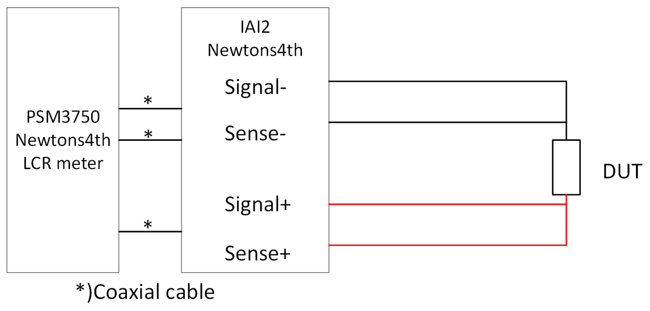
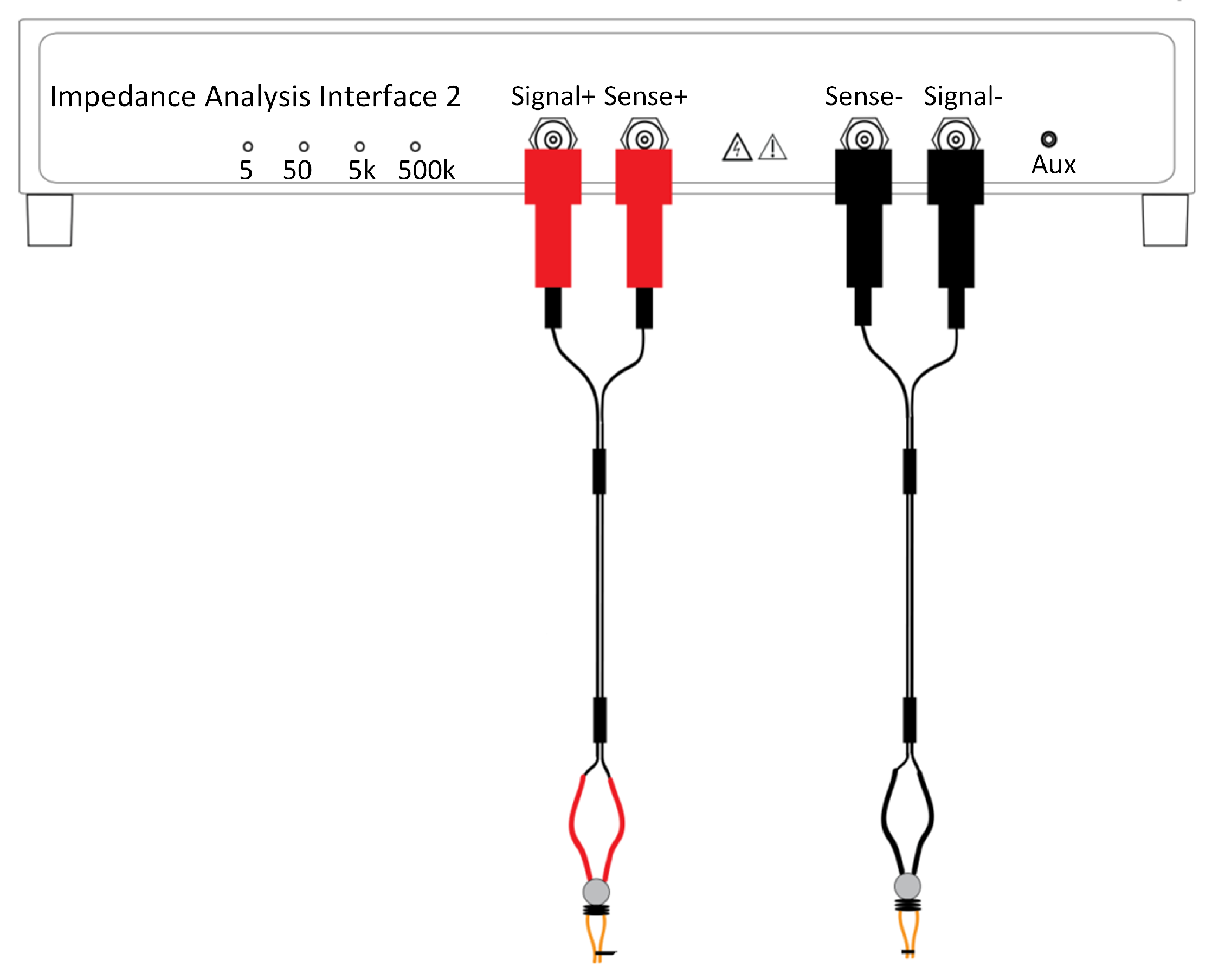
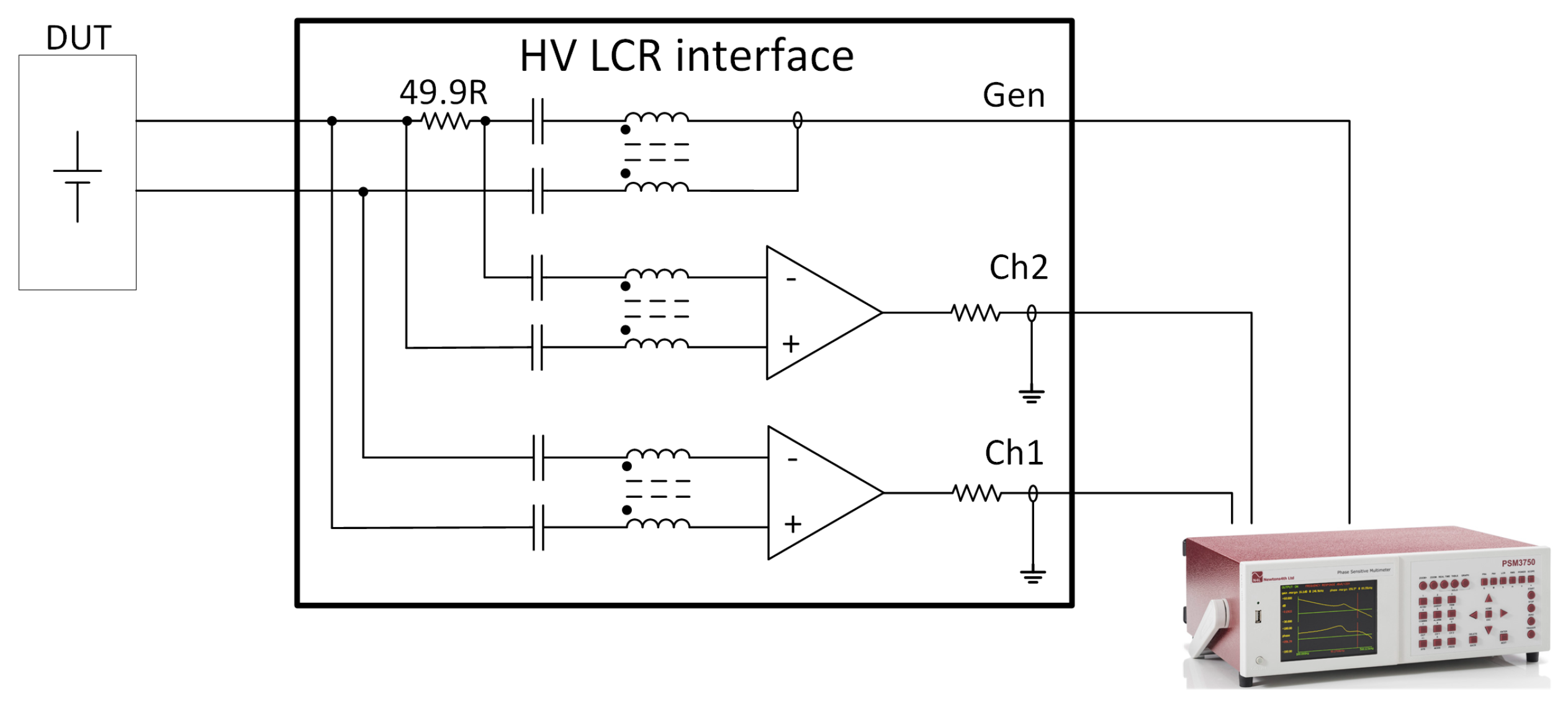
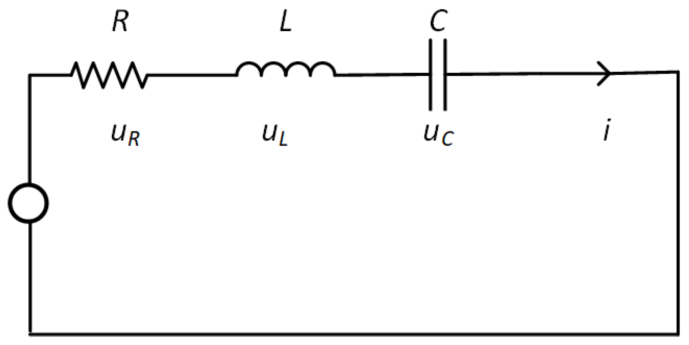
2.1. Measurements for Model Calibration
2.2. Simplification of System Simulation in PLECS
- (I)
- The first is the elimination of parasitic and/or intentional circuit parameters that have no or negligible impact on the simulation results in the frequency range of interest. There is, to the knowledge of the authors, no straightforward way to find candidates for parameters to eliminate, but a “qualified cut and try” approach has been successfully implemented. A model that represents a discrete component, subsystem, or vehicle system can be represented by a state–space matrix. In the simulation tool, the matrices are not the primary interface to work with, but they are useful for determining the eigenvalues of the circuit. To understand the method, a simple model is presented in Figure 6.
- (II)
- The second approach is the replacement of switching elements with ramped current sources. This method is described in detail in Section 2.3.
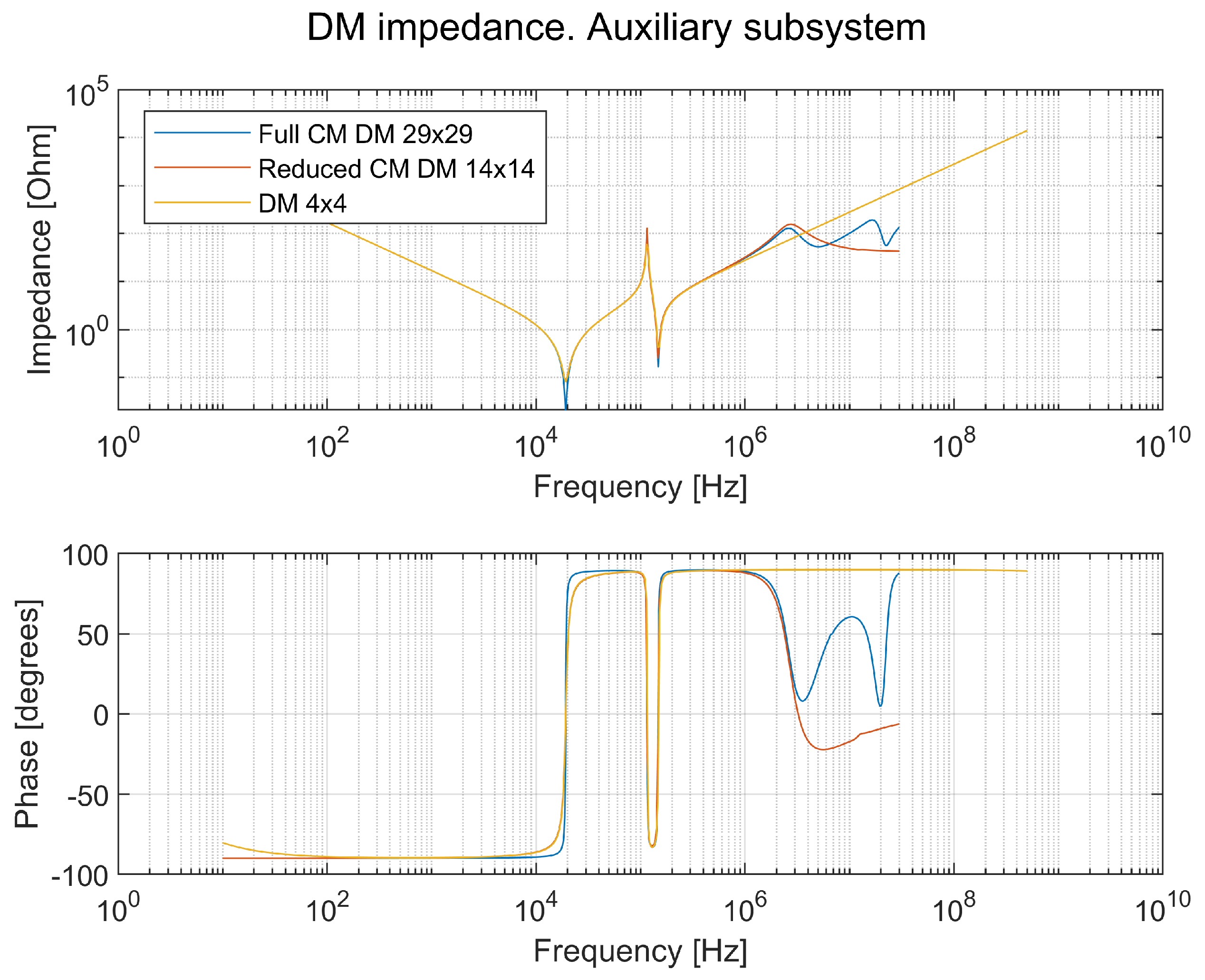
2.3. Subsystem Simplification for DM Simulation in PLECS
2.4. System Simulation Model in PLECS for DM
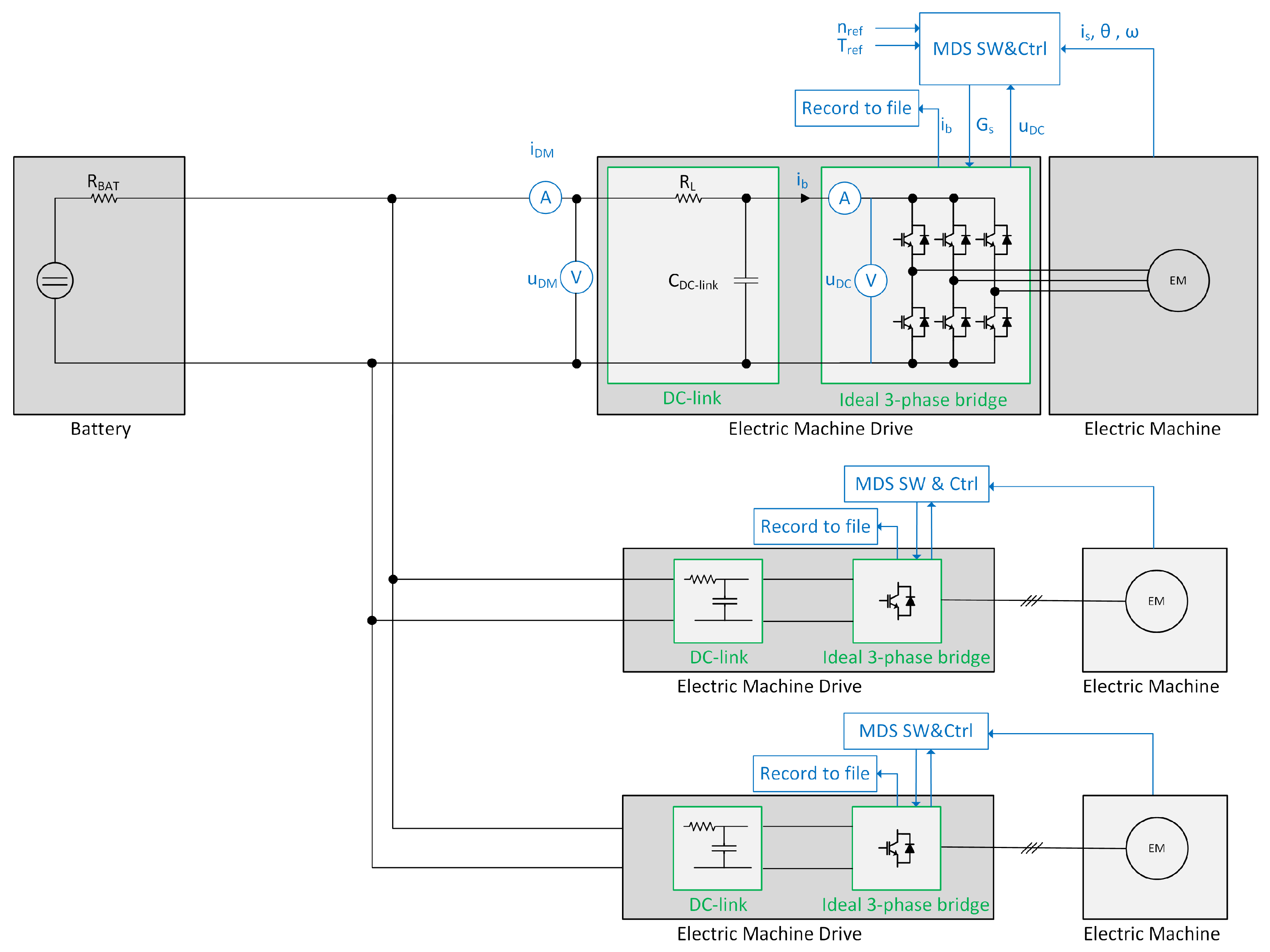
- A reduced system model with a complete MDS with active feedback control is simulated with an ideal battery and ideal cables; see Section 2.4.1.
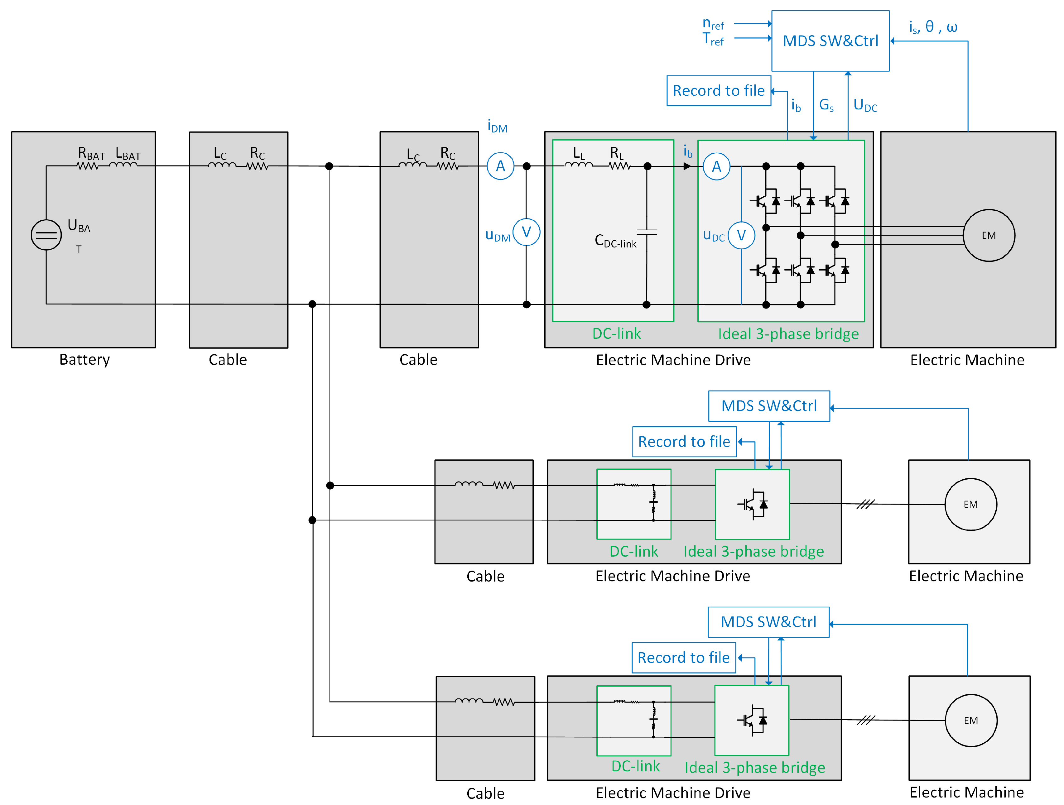
- An extended system model with DC cable models and refined battery and EMD models is simulated. The full EMD of step 1 is replaced with a DC current source mimicking the DC-link current drawn by the MDS of step 1, and a slew rate is added to the DC-link current pulses. This model thus uses a more advanced system model but with an EMD behavior as an ideal model; see Section 2.4.2.
- An extended system model with a complete MDS with active feedback control is simulated; see Section 2.4.3. It is the same case as in item 2 but with the complete MDS, including feedback.
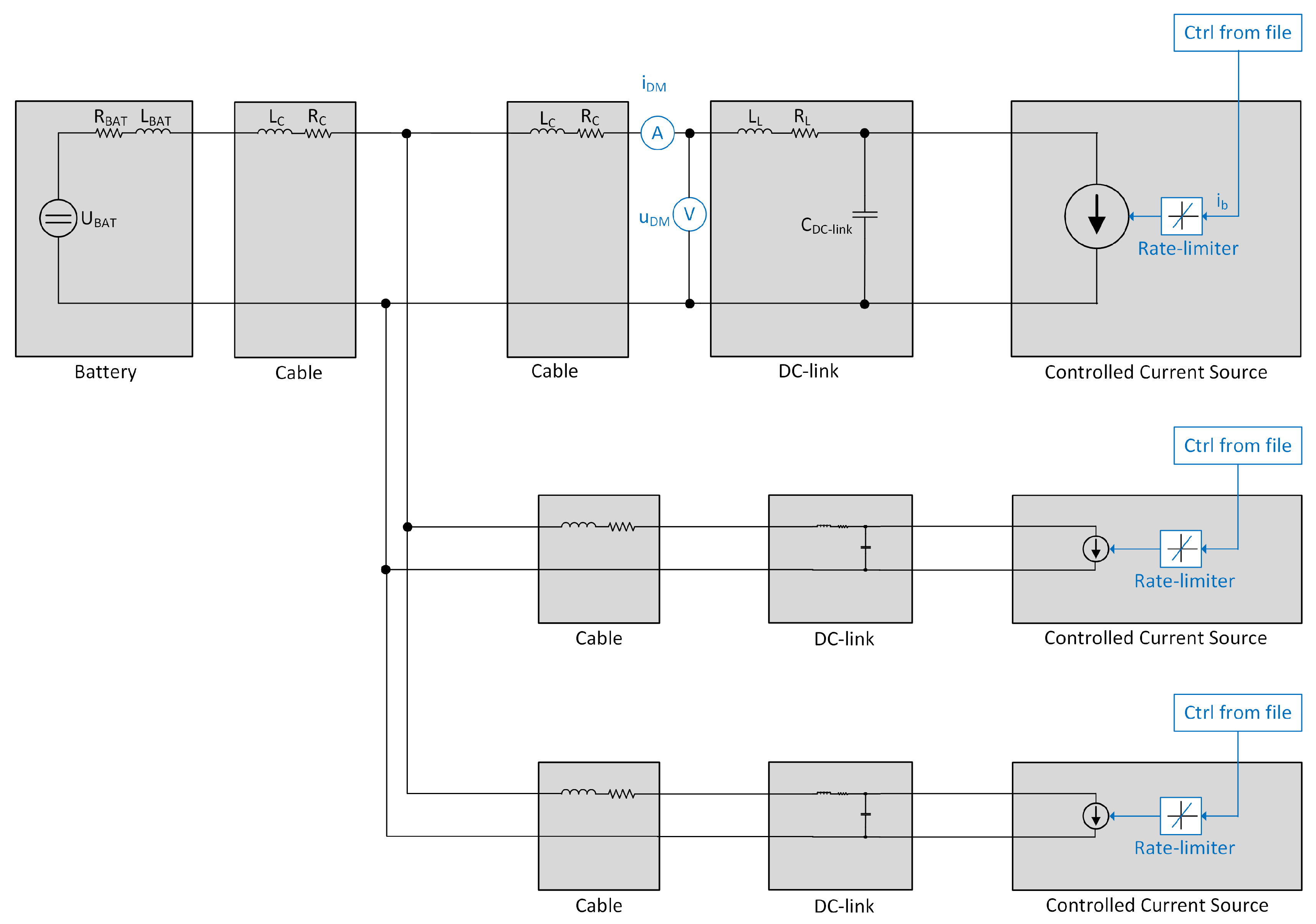
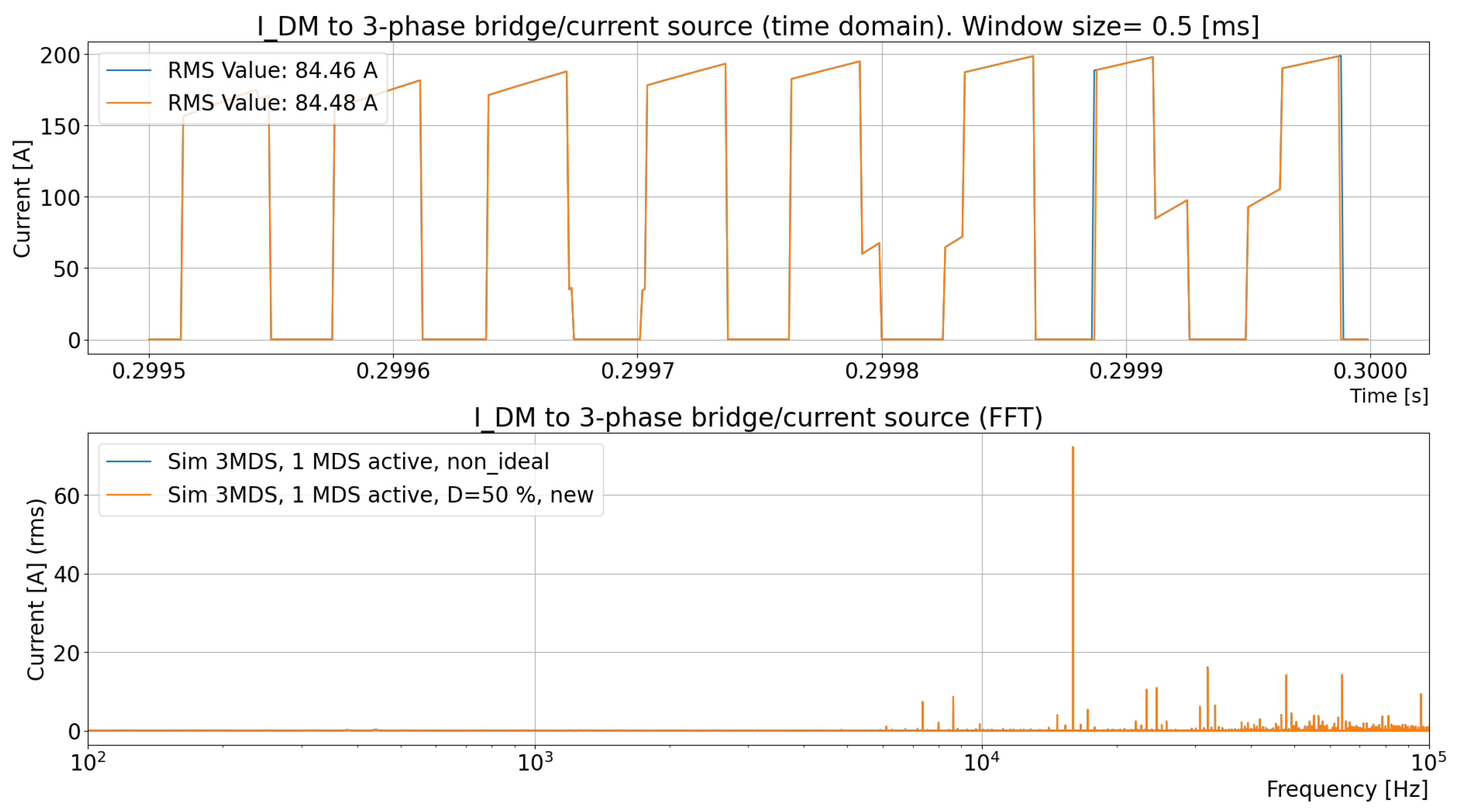
- The extended system model from step 3 is simulated again with a current source with the DC current drawn by the MDS from step 1; the MDS is replaced, and a slew rate is added to the DC-link current pulses. This model thus uses a more advanced system model but with an EMD behavior to account for the effects of the extended system model. The hypothesis is that these steps show the extent to which a complete MDS can be replaced by a current source with an adjustable slew rate. In these system simulations, the system simulation complexity and simulation time are significantly reduced; see Section 2.4.4. The results of the different simulation models in items 3 and 4 are compared.
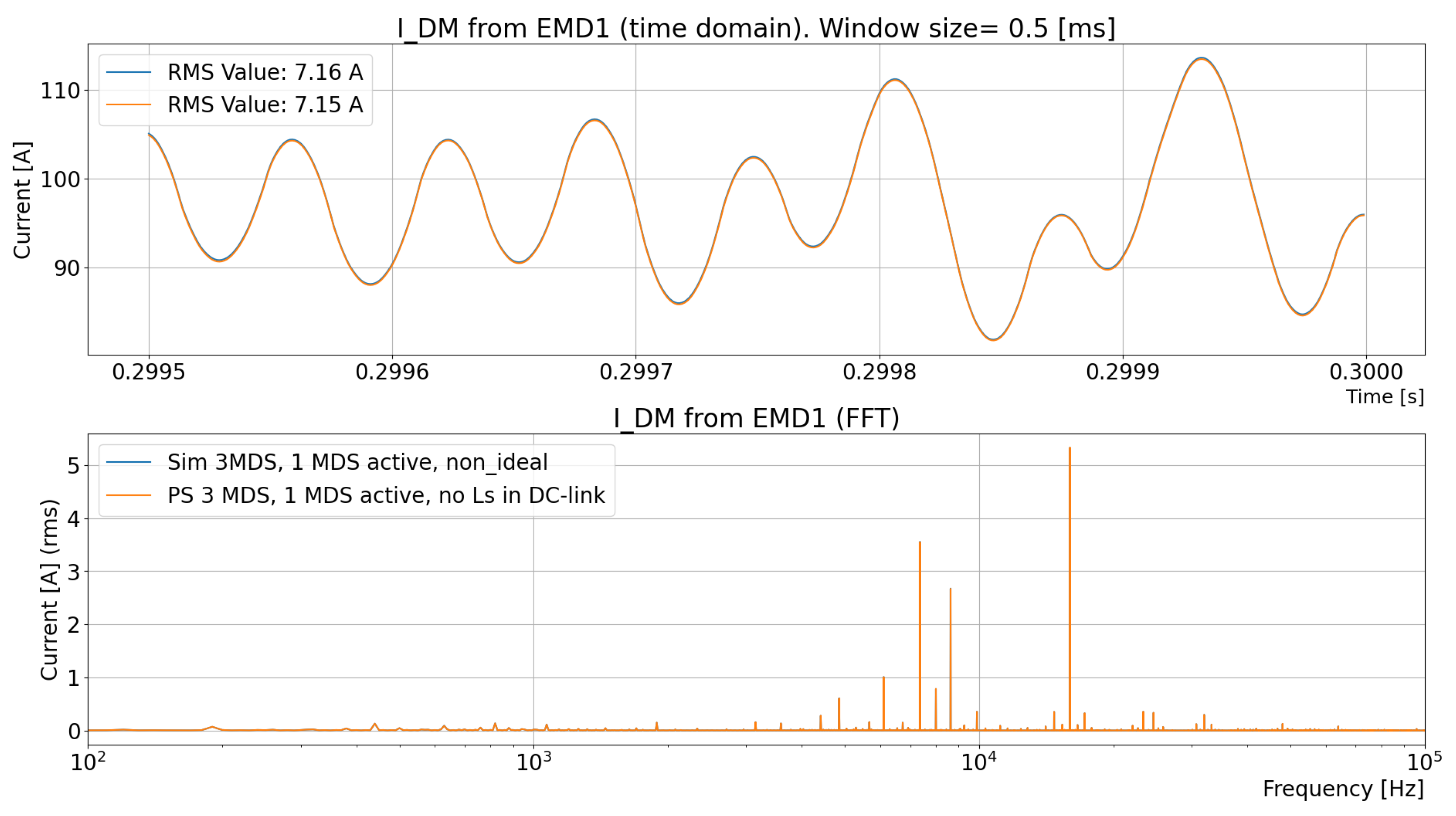
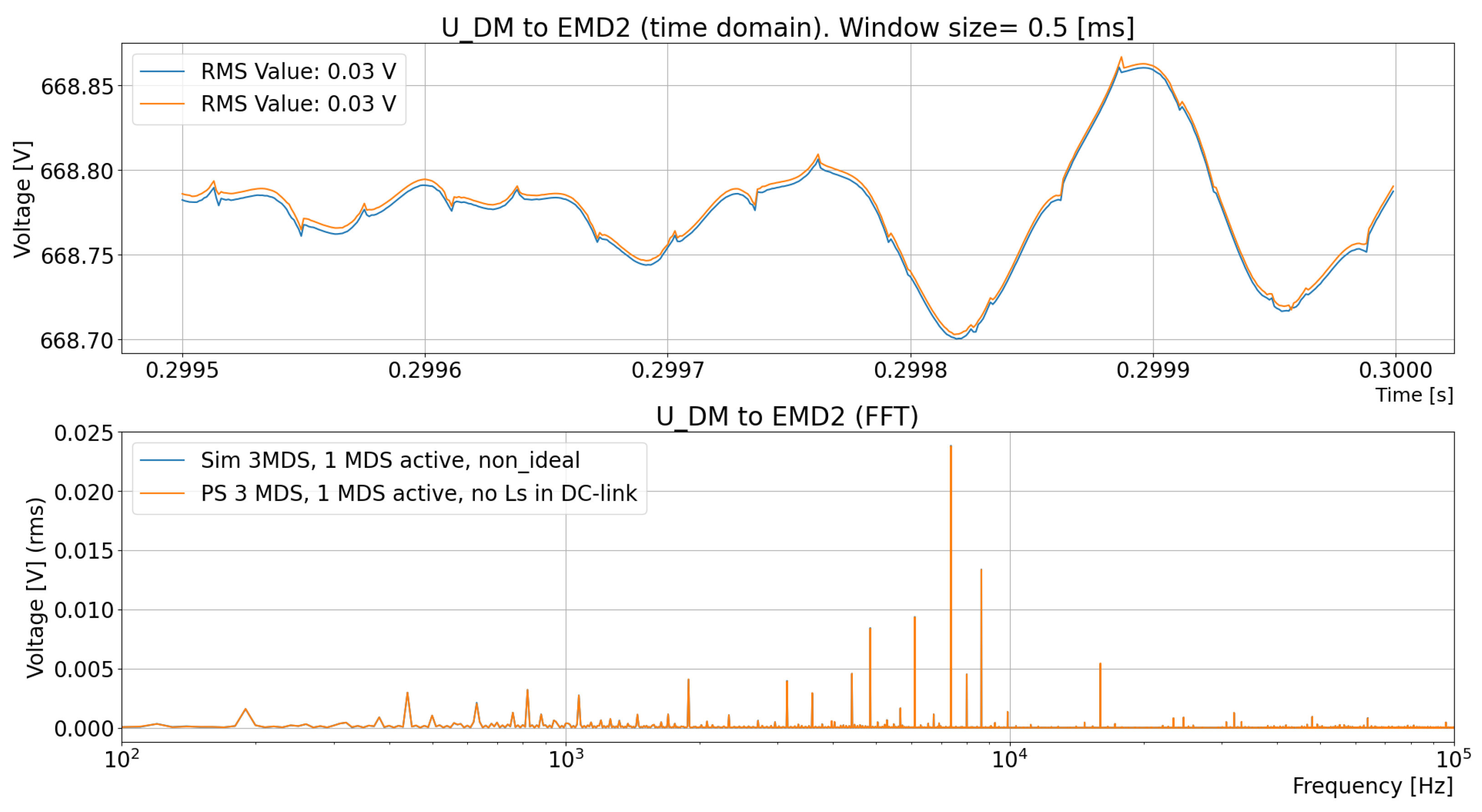
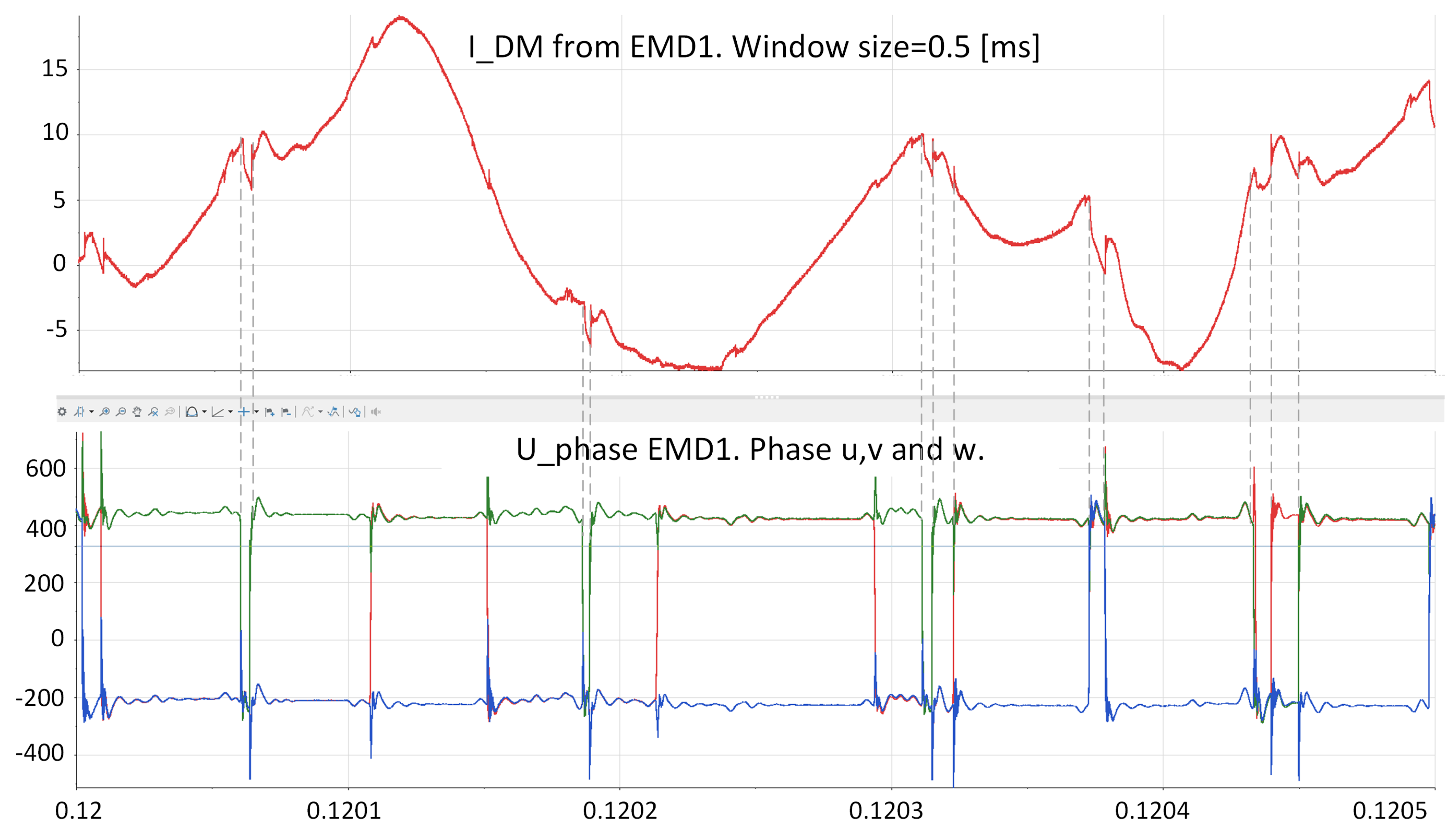
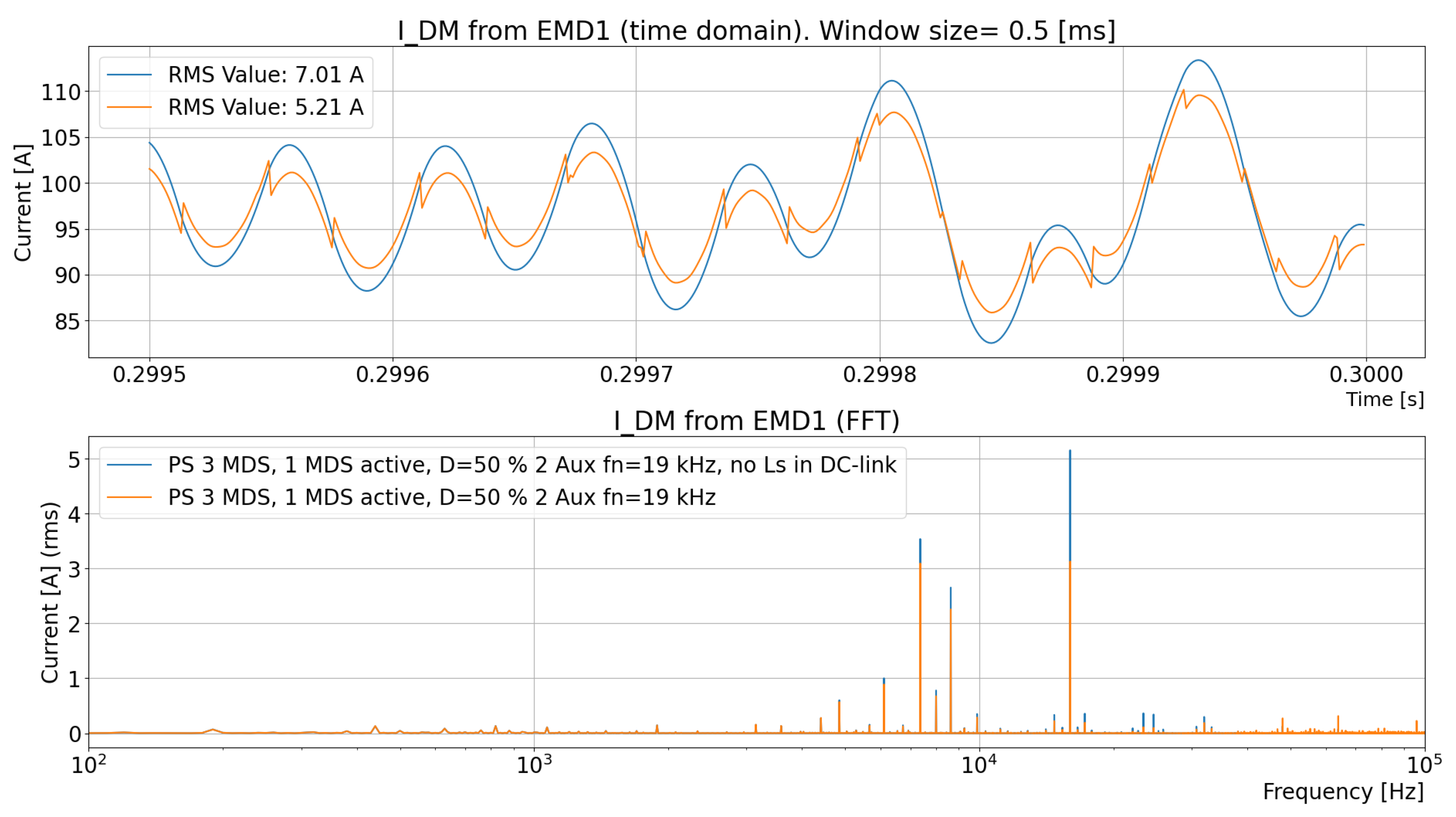
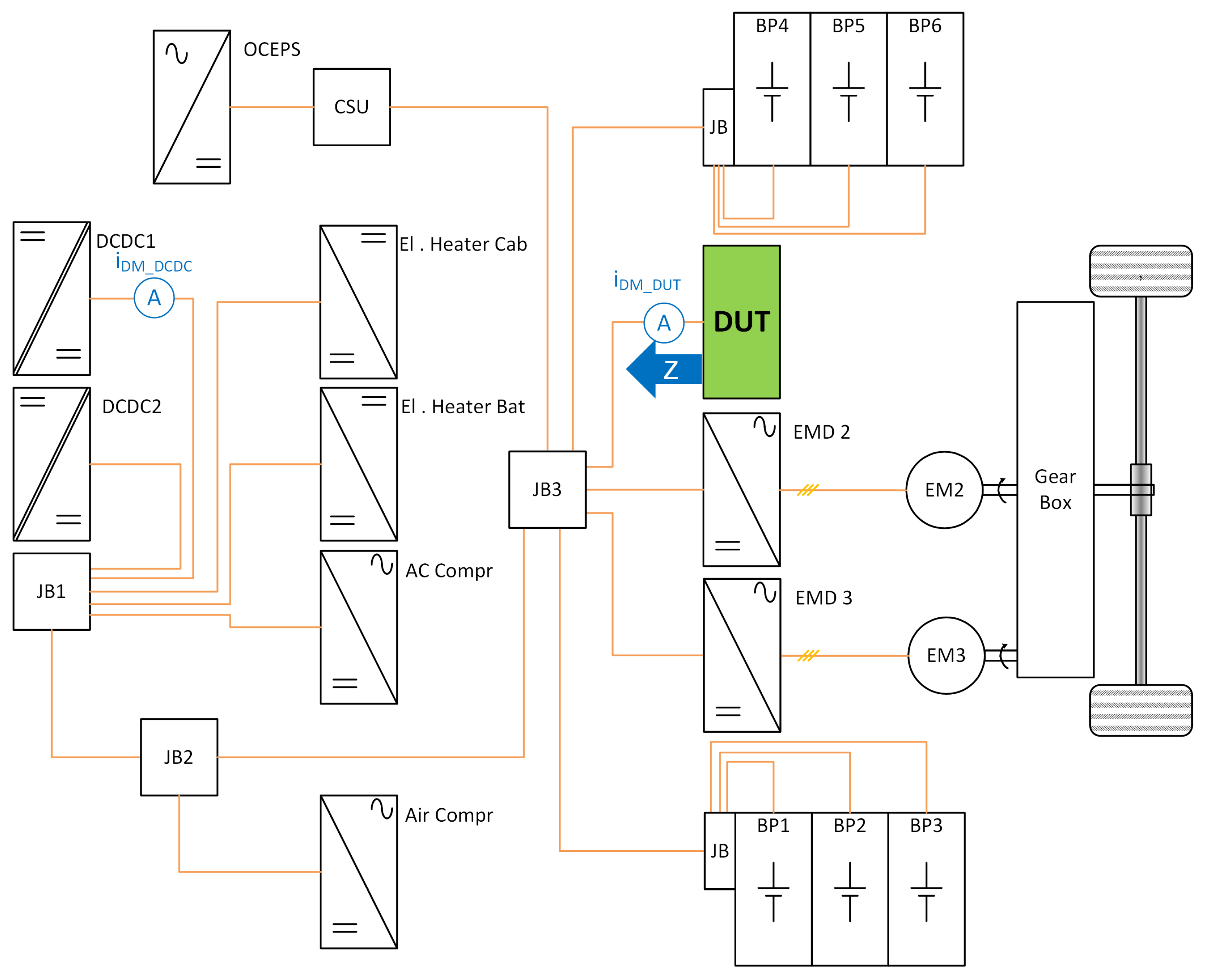
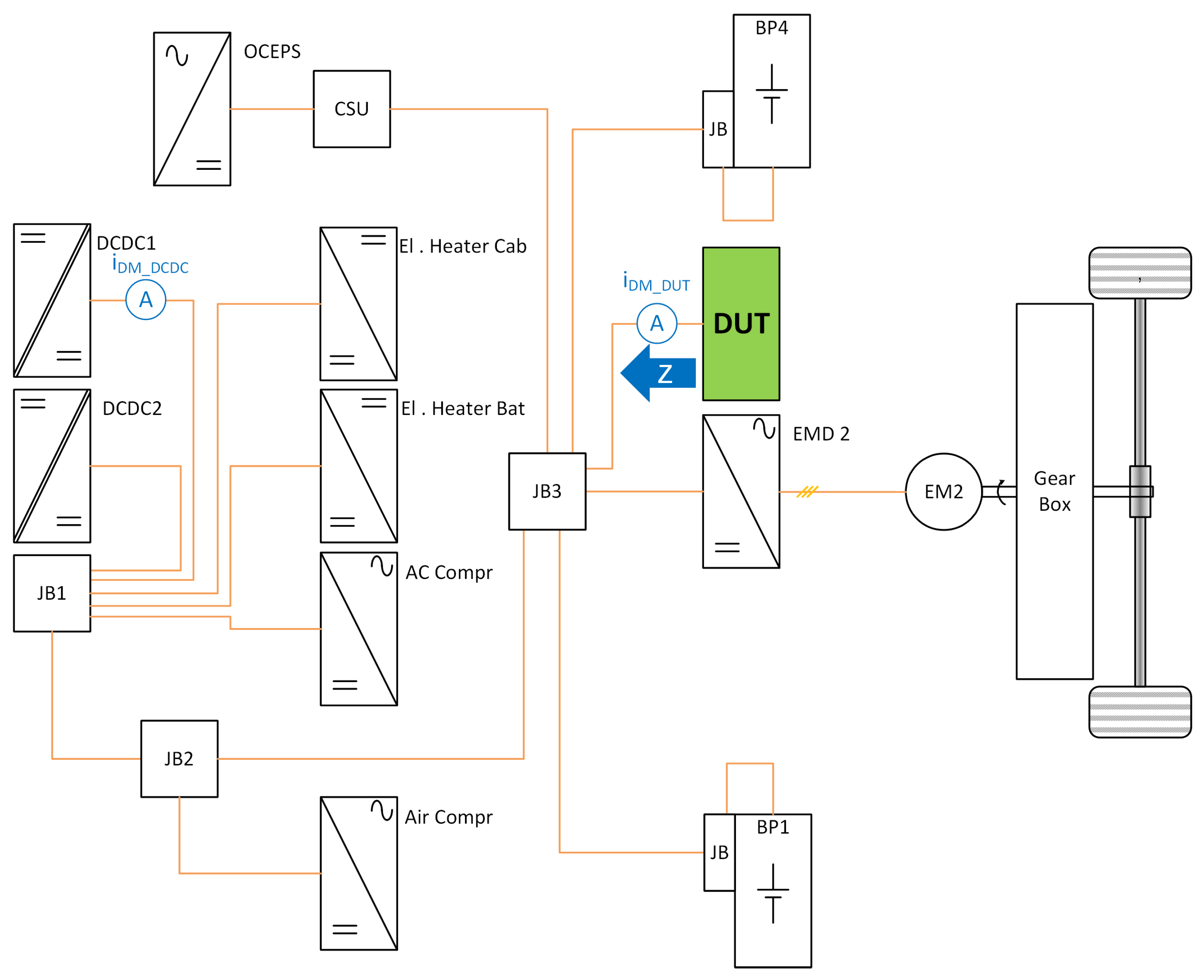
- The DC DM current to the EMD caused by the impact of the DC-link capacitor’s stray inductance is compared. This comparison involves a measurement from a real vehicle, as shown in Figure 1; see Section 2.4.5.
- A conclusion is drawn regarding items 1–5; see Section 2.4.6.
2.4.1. Reduced System Model with a Complete MDS with Active Feedback Control
2.4.2. Extended System Models Where the EMD Models Are Simulated with a Current Source and the DC Current Is Drawn by the MDS
2.4.3. Extended System Model with a Complete MDS with Active Feedback Control
2.4.4. Extended System Model from Section 2.4.3 Where the EMD Model Is Simulated with a Current Source with the DC Current Drawn by the MDS
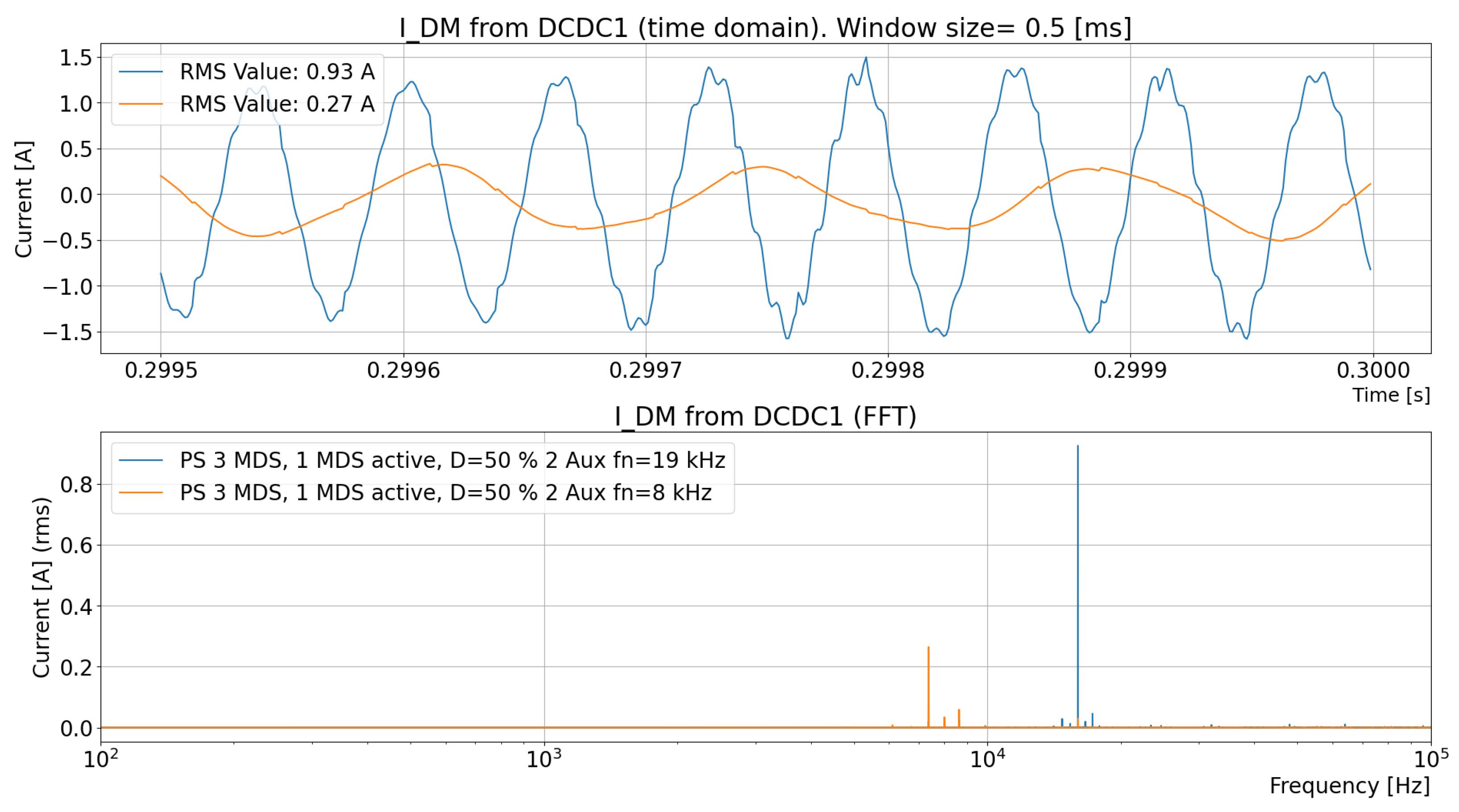
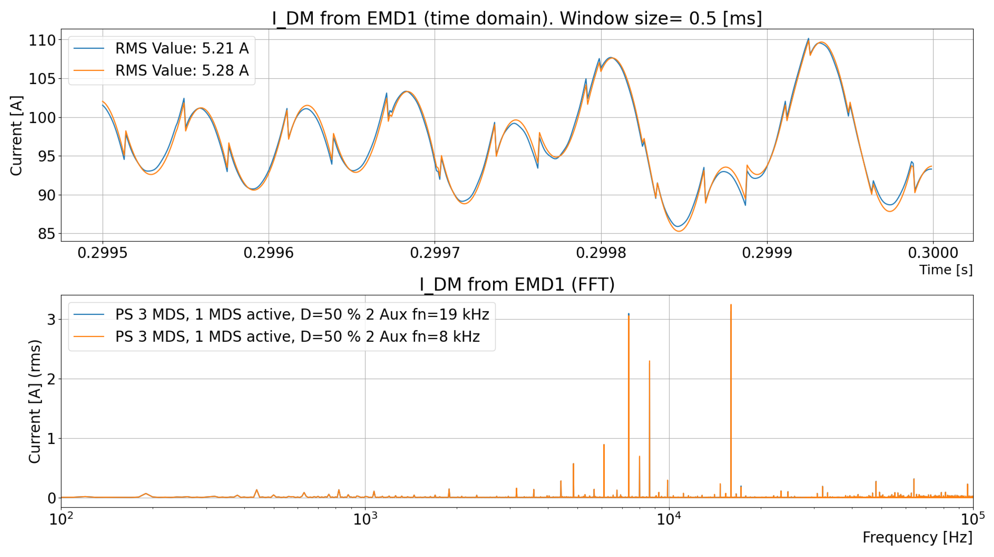
2.4.5. Comparing the Simulation Models with Measurements
2.4.6. Conclusion for the Simulation Model
- MDS with active feedback control and MDS replaced by a controlled current source;
- The DM current to the three-phase bridge, , when the system uses ideal vs. nonideal components or additional subsystems.
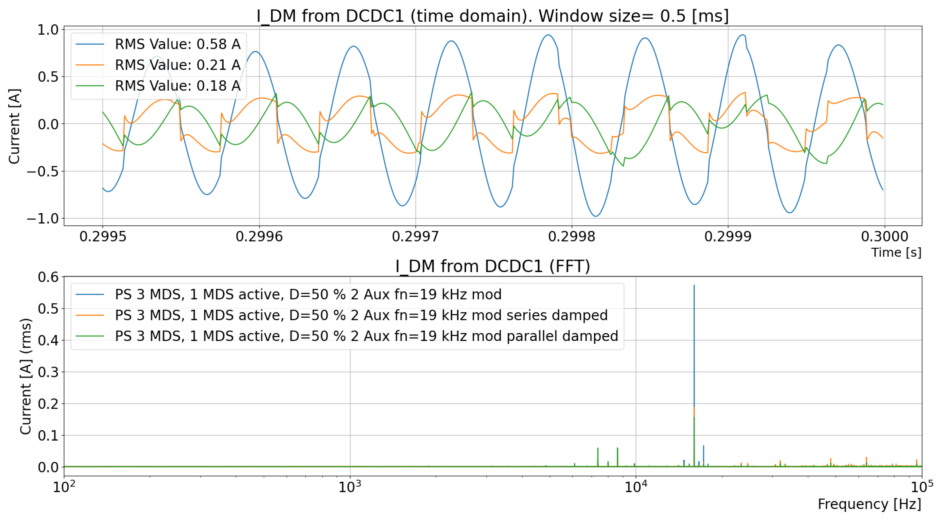
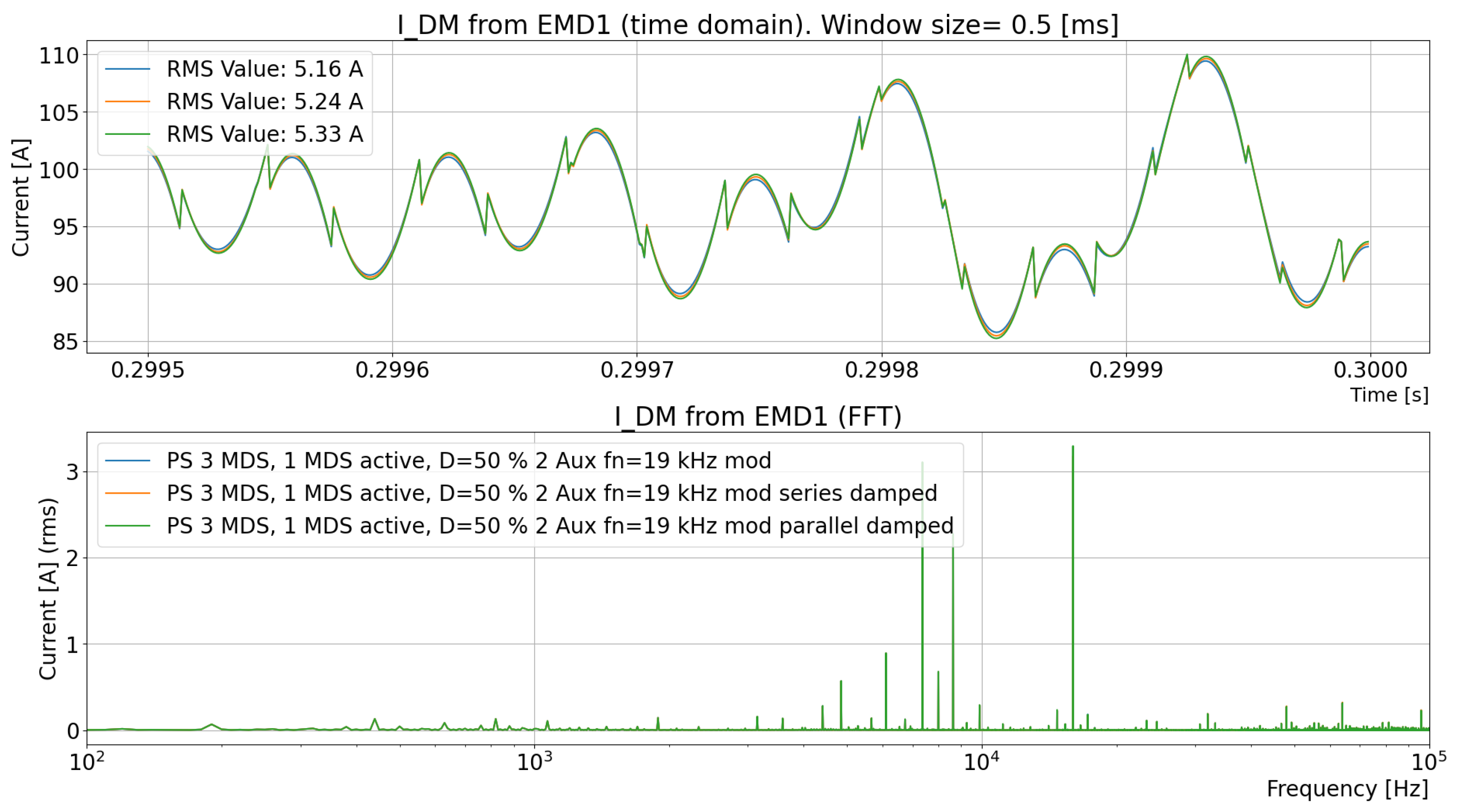
- Excluding or including the stray inductance in the DC-link capacitor.
- A simulation model with a controlled current source, from the recorded current to the three-phase bridge , can be used.
- The current to the three-phase bridge, , is independent if the system changes, as demonstrated in this study.
- The stray inductance in the DC-link capacitor, , cannot be omitted if the DM DC-link voltage, , should be properly modeled.
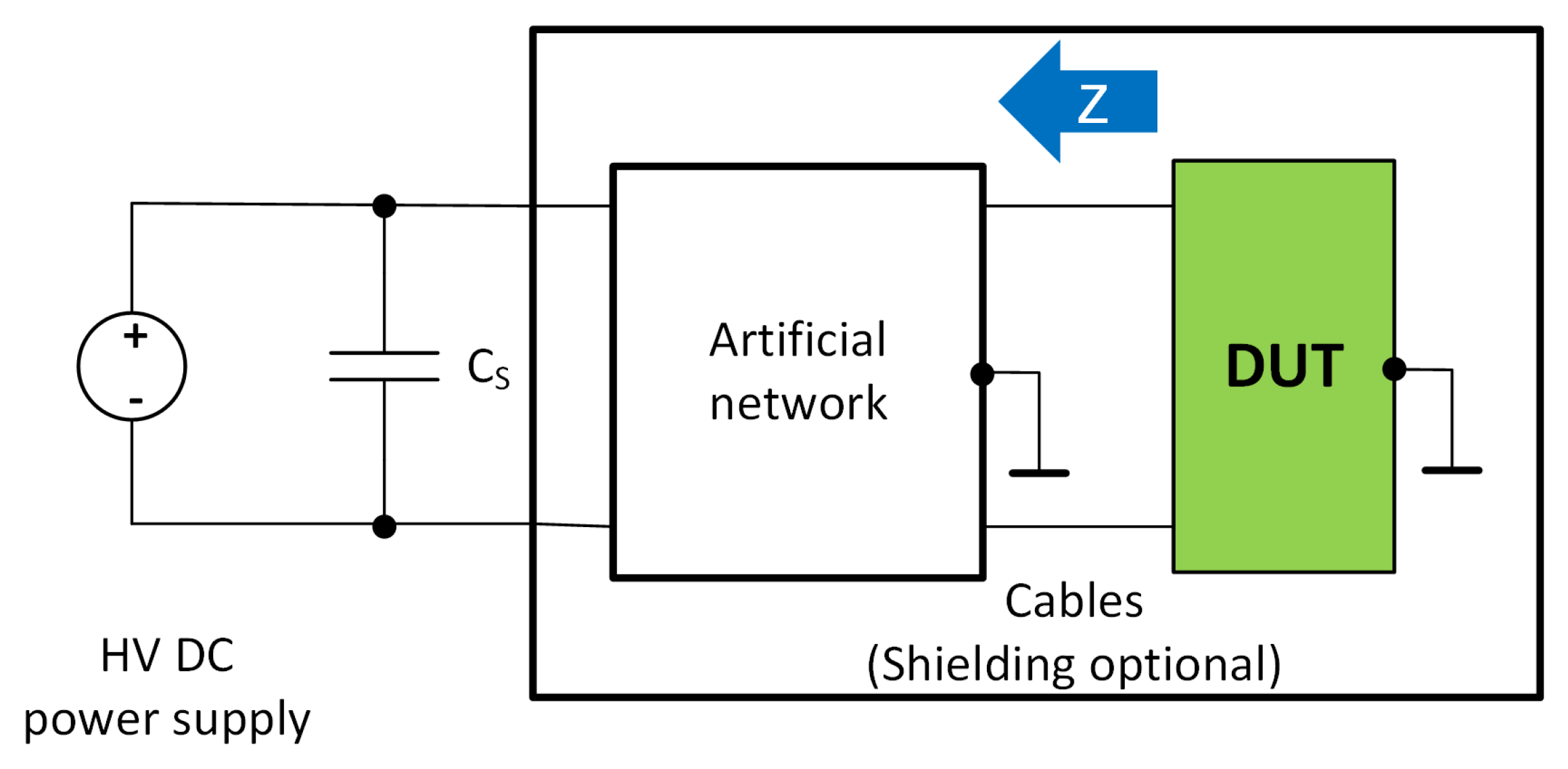
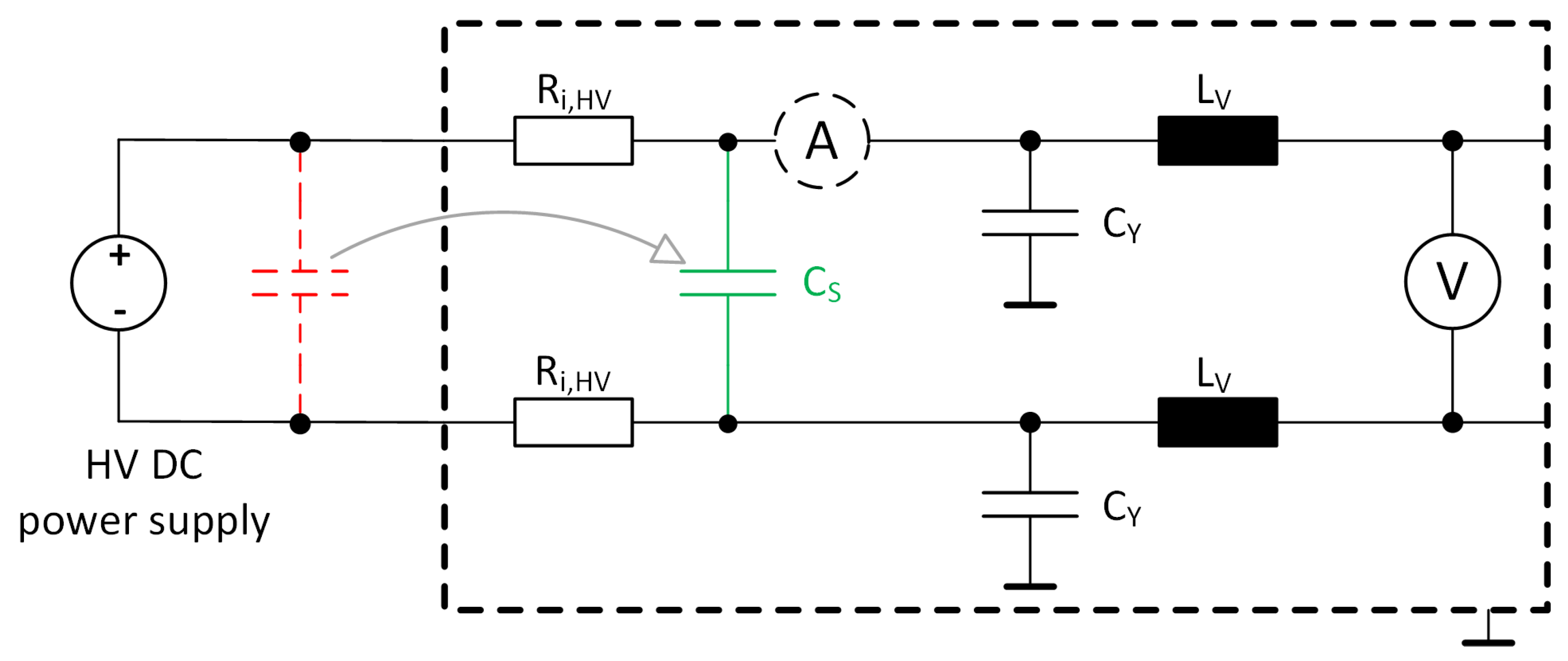
2.5. Line Impedance Stabilization Network (LISN) Model in PLECS
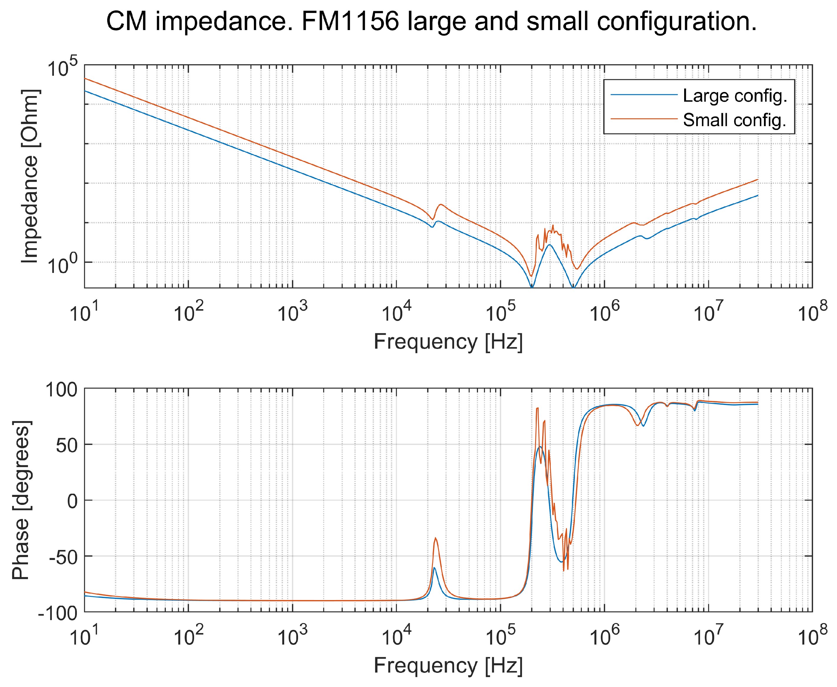
2.6. Characteristics of a TVS
- Battery: Ideal voltage source, internal resistance, CM and DM inductance, and CM parasitic capacitance towards the ground.
- Converter: DC-link capacitance, filter inductance, and CM capacitance .
- Cables: Resistance and inductance.
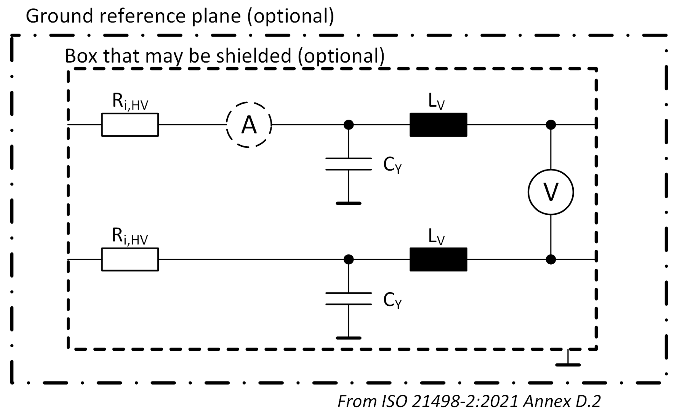
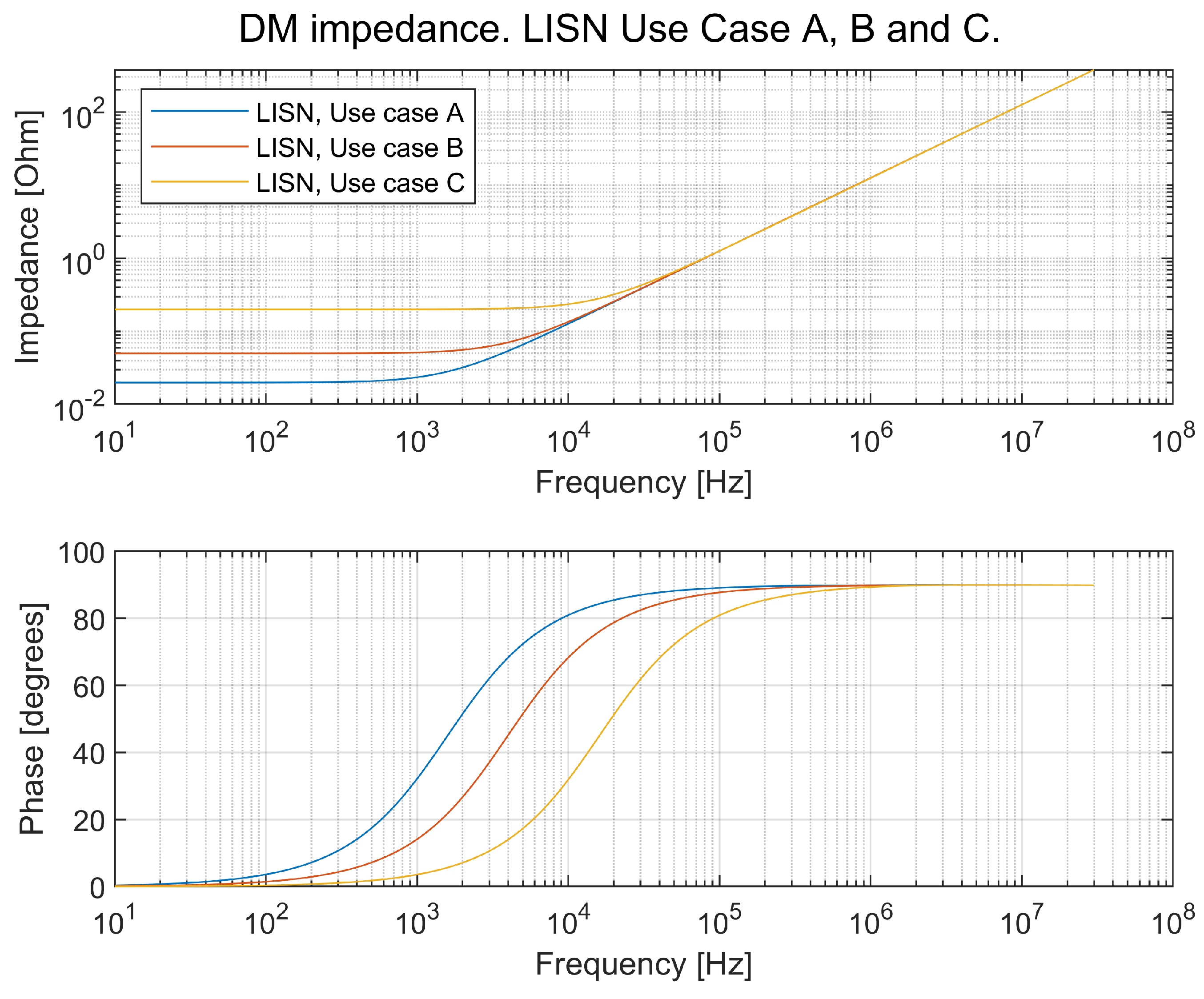
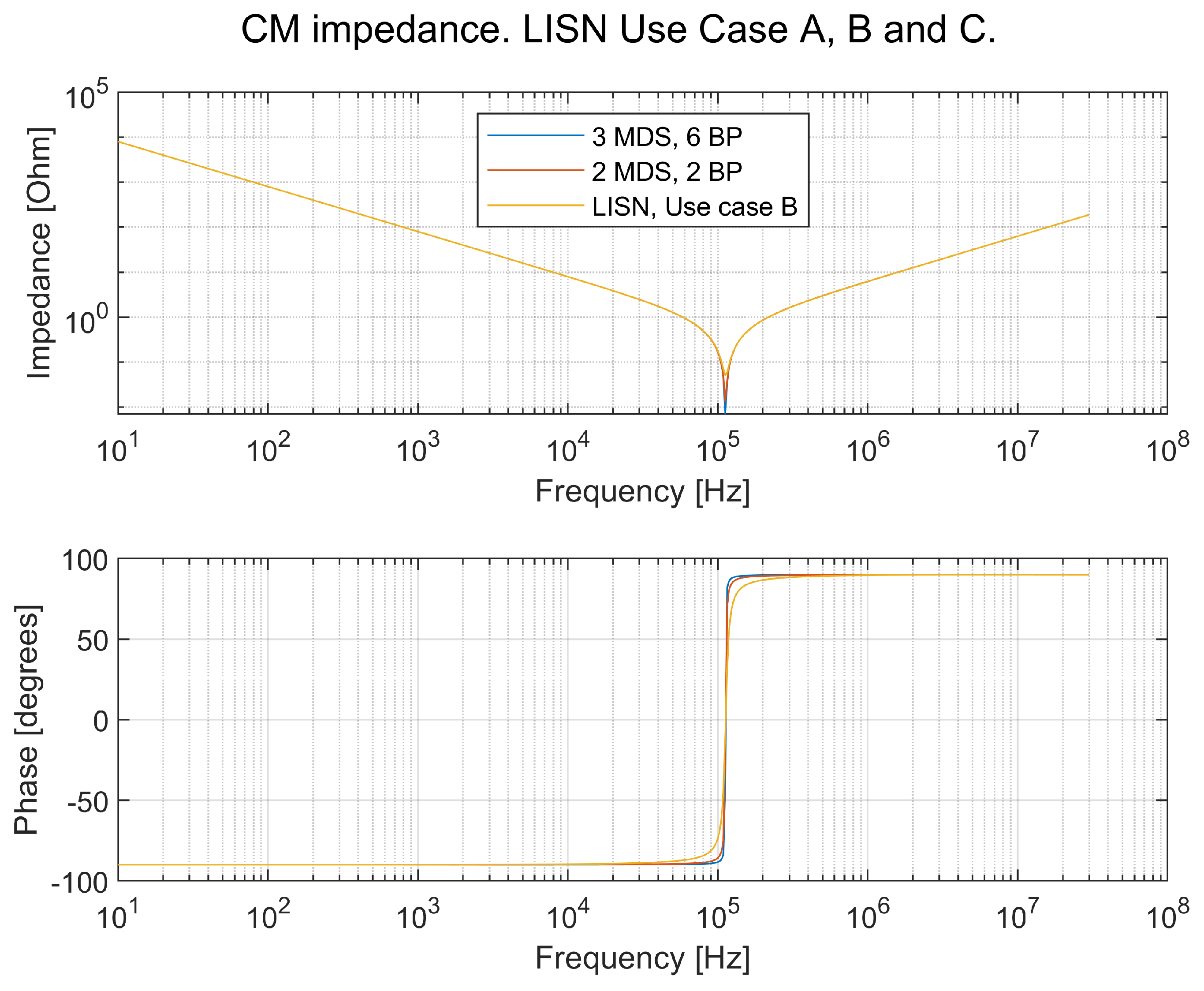
2.7. Characteristics of an LISN
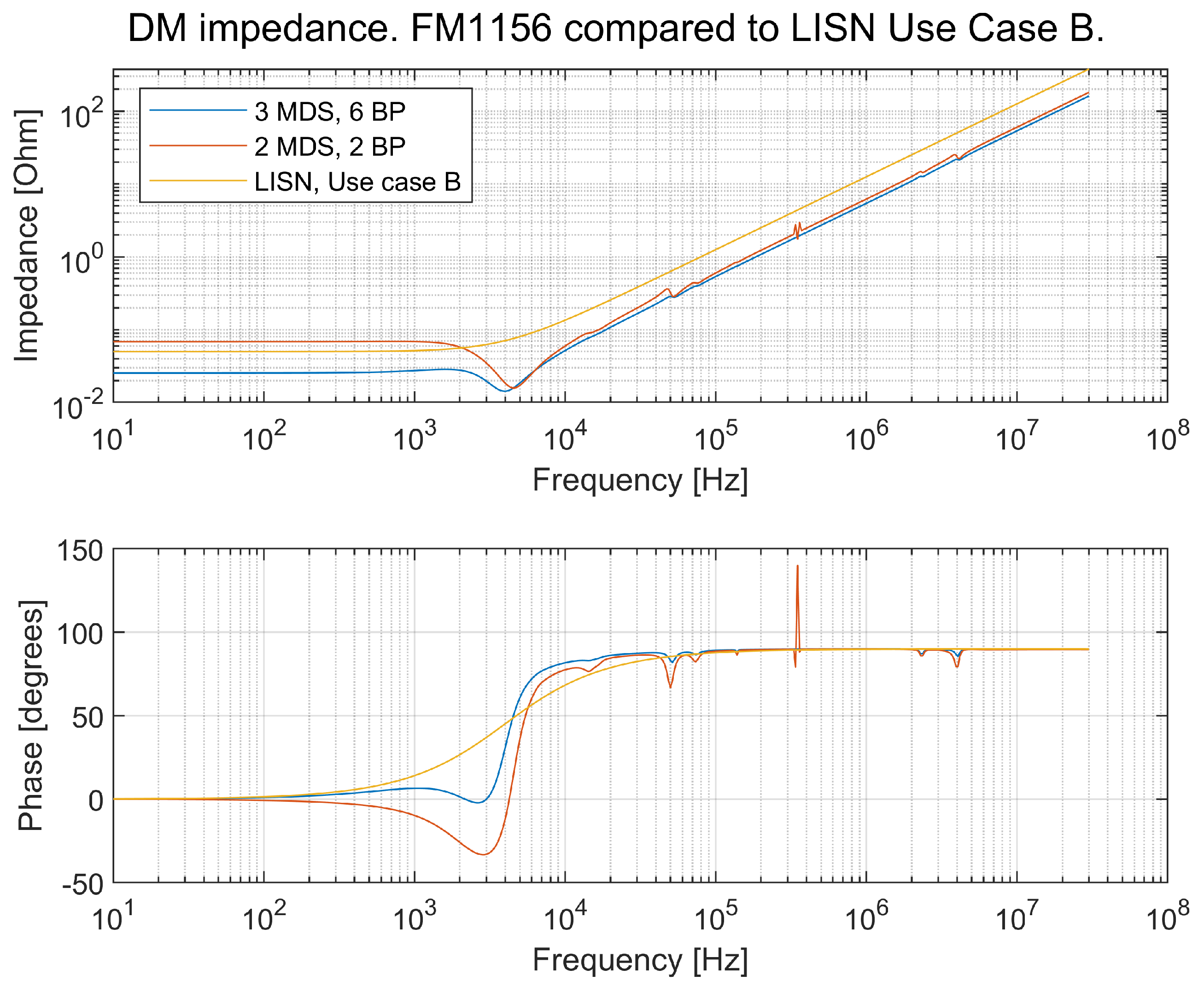
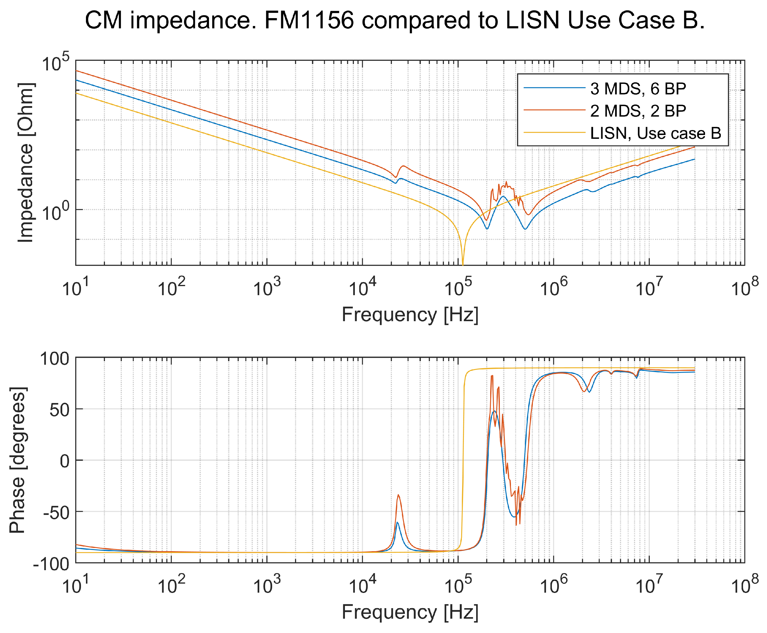
2.8. Impedance Comparison of an Artificial Network, an LISN, and Measurements on a Real Truck
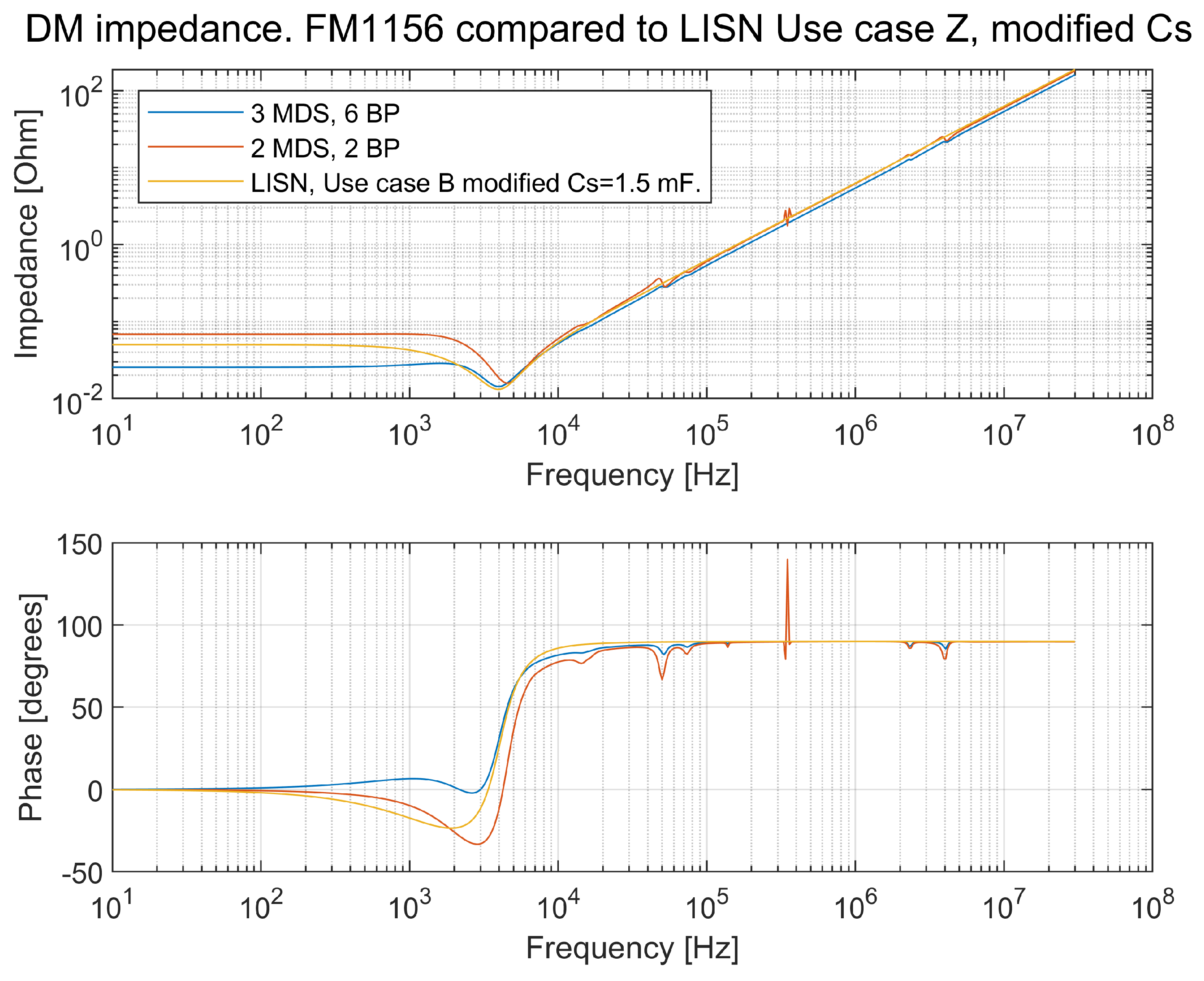
2.9. Alternative LISN
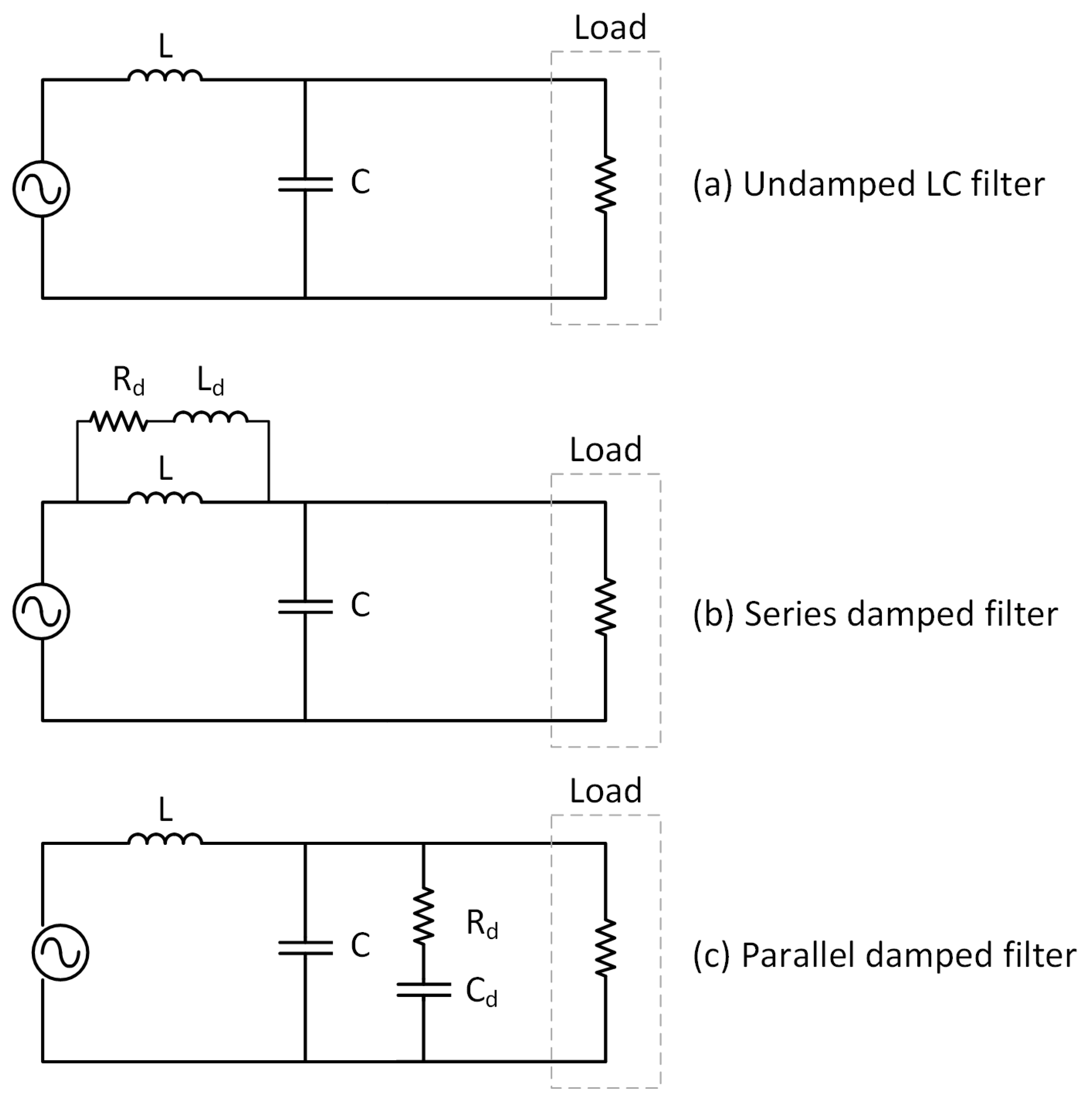
2.10. Protecting Subsystems from EMI
3. Results
3.1. Results from a Simulation of a Truck Model Compared with an LISN
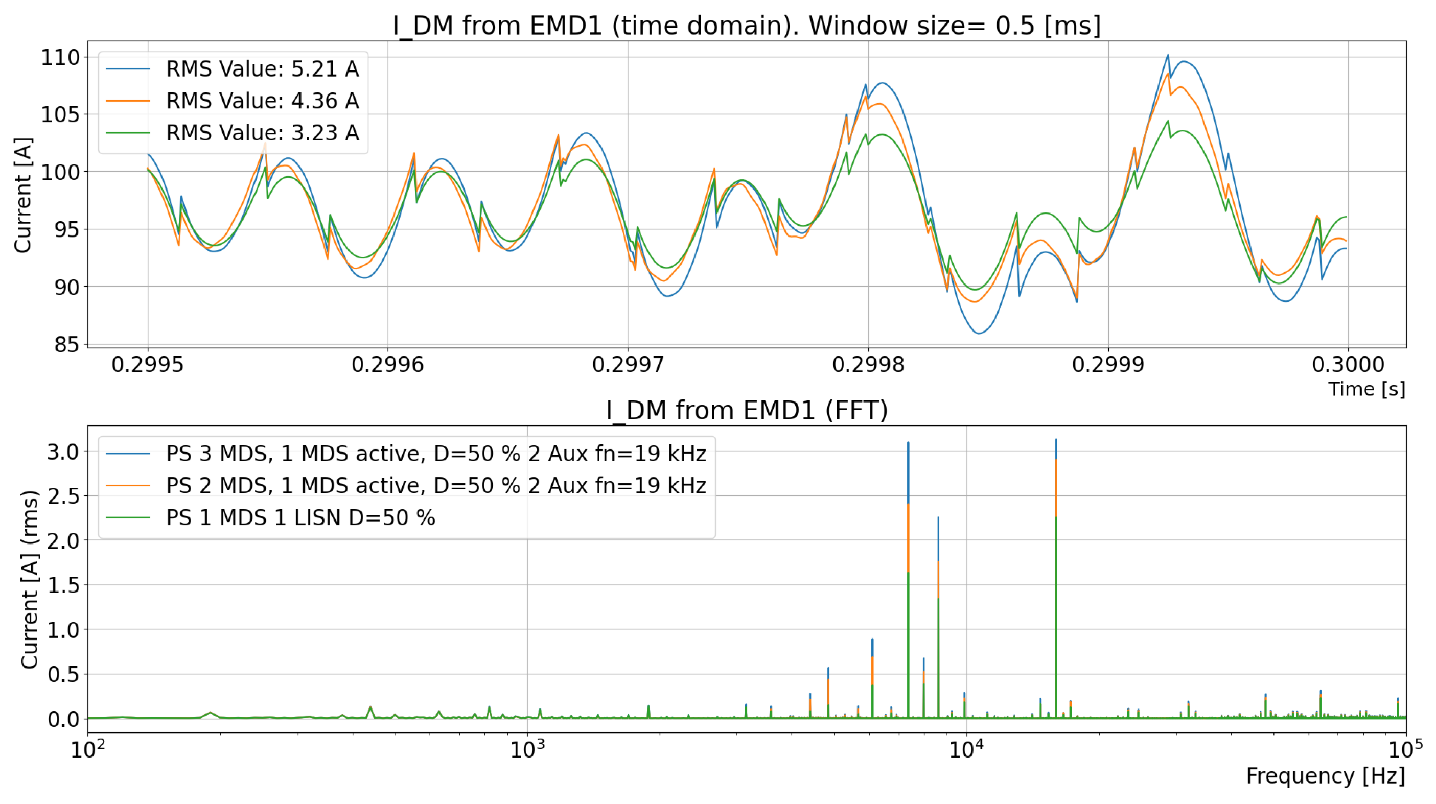
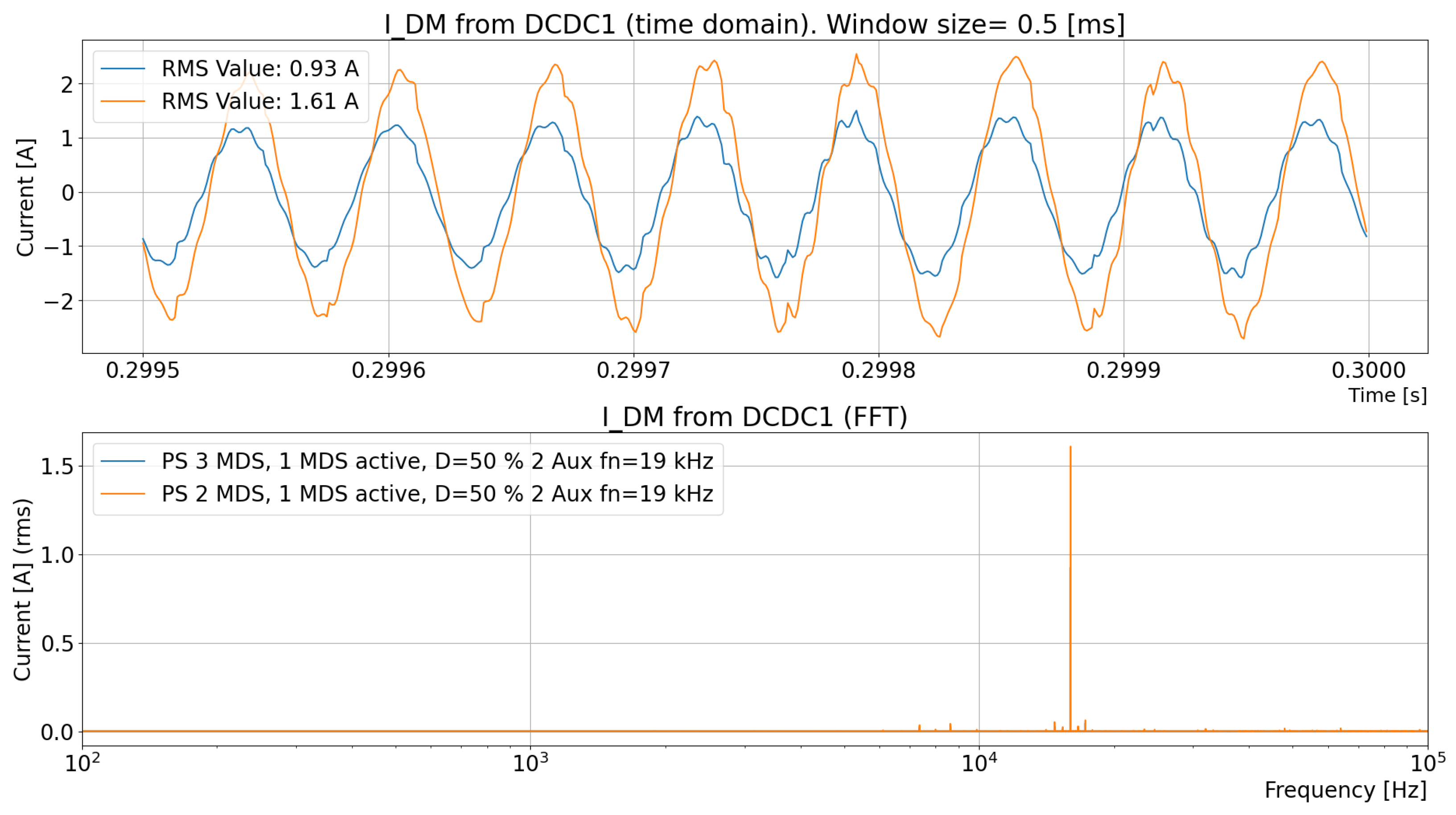
3.2. What Happens Inside the TVS That Is Not Observed with the LISN?
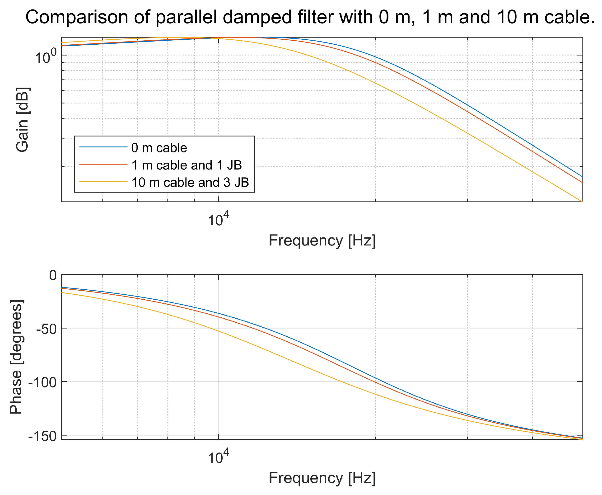
3.3. Damped Filters in the Subsystems
4. Discussion
5. Conclusions
5.1. Conclusions from the Development of the System Simulation Model
5.2. Conclusions from Simulations with the LISN
5.3. Conclusions from the DM Filters
5.4. Recommendations for Future Research
Author Contributions
Funding
Data Availability Statement
Acknowledgments
Conflicts of Interest
Abbreviations
| AC | Alternating Current |
| AC Compr. | Air Condition Compressor |
| BoB | Breakout Box |
| BP | Battery Pack |
| CSU | Charging Switch Unit |
| CM | Common Mode |
| DC | Direct Current |
| DC/DC | DC/DC converter, converts 700 V DC to 24 V DC |
| DM | Differential Mode |
| DUT | Device Under Test |
| EM | Electric Machine |
| EMC | Electromagnetic Compatibility |
| EMD | Electric Machine Drive |
| EMI | Electromagnetic Interference |
| G2V | Grid-to-Vehicle |
| HV | High Voltage (in this article, in the range of max 1000 V) |
| IGBT | Insulated-Gate Bipolar Transistor |
| LISN | Line Impedance Stabilization Network |
| IP | Intellectual Property |
| JB | Junction Box |
| MDS | Machine Drive System |
| OCEPS | Onboard Charger and Electrical Power Supply |
| OEM | Original Equipment Manufacturer |
| NI | National Instrument |
| PEC | Power Electronic Converter |
| PLECS | Power Electronics Simulation Software (by PLEXIM) |
| RMS | Root Mean Square |
| SW | Software |
| TVS | Traction Voltage System |
| V2G | Vehicle-to-Grid |
| V2V | Vehicle-to-Vehicle |
References
- Schiedermeier, M.; Rettner, C.; Heilmann, M.; Schneider, F.; März, M. Interference of automotive HV-DC-systems by traction voltage-source-inverters (VSI). In Proceedings of the 2019 IEEE Transportation Electrification Conference, ITEC-India 2019, Bengaluru, India, 17–19 December 2019. [Google Scholar] [CrossRef]
- Gürlek, Y.; Joos, O.; Lang, C.; Ackerl, M.; Dold, R.; Basler, T.; Neuburger, M. Analysis on the Impact of Current Ripples in Fuel Cell Electric Heavy-Duty Trucks. In Proceedings of the 2023 25th European Conference on Power Electronics and Applications, EPE 2023 ECCE Europe, Aalborg, Denmark, 4–8 September 2023. [Google Scholar] [CrossRef]
- Lee, Y.H.; Nasiri, A. Conductive CM and DM noise analysis of power electronic converters in electric and hybrid electric vehicles. In Proceedings of the VPPC 2007—Proceedings of the 2007 IEEE Vehicle Power and Propulsion Conference, Arlington, TX, USA, 9–12 September 2007; pp. 392–398. [Google Scholar] [CrossRef]
- Gentejohann, M.; Schluter, M.; DIeckerhoff, S.; Hepp, M. Driving Cycle Analysis of the DC Bus Current Ripple in Electric Vehicles. In Proceedings of the 2021 23rd European Conference on Power Electronics and Applications, EPE 2021 ECCE Europe, Ghent, Belgium, 6–10 September 2021. [Google Scholar] [CrossRef]
- Wang, K.; Lu, H.; Li, X. High-Frequency Modeling of the High-Voltage Electric Drive System for Conducted EMI Simulation in Electric Vehicles. IEEE Trans. Transp. Electrif. 2023, 9, 2808–2819. [Google Scholar] [CrossRef]
- Gentejohann, M.; Schlueter, M.; Dieckerhoff, S. Investigation of the Current Ripple caused by the Main Inverter in the High Voltage DC Bus of Electric Vehicles. In Proceedings of the VCIPS 2020; 11th International Conference on Integrated Power Electronics Systems, Berlin, Germany, 24–26 March 2020; Available online: https://ieeexplore.ieee.org/document/9097687 (accessed on 29 January 2025).
- Aguirre, M.; Madina, P.; Poza, J.; Aranburu, A.; Nieva, T. Analysis and comparison of PWM modulation methods in VSI-Fed PMSM drive systems. In Proceedings of the 2012 20th International Conference on Electrical Machines, ICEM 2012, Marseille, France, 2–5 September 2012; pp. 851–857. [Google Scholar] [CrossRef]
- Bierhoff, M.H.; Fuchs, F.W. DC-link harmonics of three-phase voltage-source converters influenced by the pulsewidth-modulation strategy—An analysis. IEEE Trans. Ind. Electron. 2008, 55, 2085–2110. [Google Scholar] [CrossRef]
- EPCI. Losses (ESR, IMP, DF, Q); European Passive Components Institute: Lanskroun, Czech Republic, 2020; Available online: https://epci.eu/capacitors-losses-esrimpdfq (accessed on 19 September 2019).
- Kishore, A.; Patki, C.; Anwar, M.; Ivan, W.; Teimor, M. Investigation of common mode noise in electric propulsion system high voltage components in an electrified vehicle. In Proceedings of the 2016 IEEE Transportation Electrification Conference and Expo, ITEC 2016, Dearborn, MI, USA, 27–29 June 2016. [Google Scholar] [CrossRef]
- Mutoh, N.; Nakanishi, M.; Kanesaki, M.; Nakashima, J. EMI noise control methods suitable for electric vehicle drive systems. IEEE Trans. Electromagn. Compat. 2005, 47, 930–937. [Google Scholar] [CrossRef]
- Amjadifard, R.; Bina, M.T.; Khaloozadeh, H.; Bagheroskouei, F. Proposing an Improved DC LISN for Measuring Conducted EMI Noise. IEEE Trans. Electromagn. Compat. 2021, 63, 752–761. [Google Scholar] [CrossRef]
- Reuter, M.; Tenbohlen, S.; Köhler, W.; Ludwit, A. Impedance analysis of automotive high voltage networks for EMC measurements. In Proceedings of the 10th International Symposium on Electromagnetic Compatibility, York, UK, 26–30 September 2011; Available online: https://ieeexplore.ieee.org/document/6078538 (accessed on 24 October 2024).
- Reuter, M.; Tenbohlen, S.; Köhler, W. Characterization of automotive high voltage networks for EMI measurements. In Proceedings of the 2010 Emobility—Electrical Power Train, EEPT 2010, Leipzig, Germany, 8–9 November 2010. [Google Scholar] [CrossRef]
- Widek, P.; Alakula, M. Modeling of electric power system in electric vehicles. In Proceedings of the 2020 International Symposium on Power Electronics, Electrical Drives, Automation and Motion (SPEEDAM), Sorrento, Italy, 24–26 June 2020; pp. 293–298. [Google Scholar] [CrossRef]
- Widek, P. Modeling of Electric Power Systems in Electric Vehicles. 2022. Available online: https://www2.iea.lth.se/publications/theses/lth-iea-1094.pdf (accessed on 29 January 2025).
- Widek, P.; Alakula, M. Common Mode Current Measurements in Traction Systems for Electric Vehicles. IEEE Trans. Ind. Appl. 2023, 59, 2061–2068. [Google Scholar] [CrossRef]
- Widek, P.; Ottosson, J. Common Mode Current Reduction in Traction Systems for Electric Vehicles. In Proceedings of the 2024 International Symposium on Power Electronics, Electrical Drives, Automation and Motion (SPEEDAM), Napoli, Italy, 19–21 June 2024; pp. 742–749. [Google Scholar] [CrossRef]
- Newtons4th. PSM3750 Frequency Response Analyzer: 10 µHz–50 MHz—High Performance—Newtons 4th|Power Analyzers and Frequency Analyzers. 2021. Available online: https://www.newtons4th.com/products/frequency-response-analyzers/psm3750/ (accessed on 17 March 2021).
- Newtons4th. IAI2 Impedance Analyzer—10 uHz to 50 MHz. Available online: https://www.newtons4th.com/products/impedance-analysis-interface-2/ (accessed on 1 October 2021).
- Simulation Software PLECS Blockset. Available online: https://plexim.com/products (accessed on 10 November 2021).
- ISO 21498-2:2021; Electrically Propelled Road Vehicles—Electrical Specifications and Tests for Voltage Class B Systems and Components—Part 2: Electrical Tests for Components. ISO: Geneva, Switzerland, 2021. Available online: https://www.iso.org/standard/78210.html (accessed on 26 August 2024).
- Baker, B.C. Texas Instruments 1 AAJ 3Q 2016. 2016. Available online: https://www.ti.com/lit/an/snva538/snva538.pdf (accessed on 9 April 2023).


| Subsystem | Description |
|---|---|
| EMD1–EMD3 | The electrical machine drive (EMD) provides electrical energy to or from the electrical machine (EM). The EMD converts DC to AC and AC to DC. |
| EM1–EM3 | The electrical machines (EMs) convert electrical energy into mechanical energy to propel the vehicle or convert mechanical energy into electrical energy to brake the vehicle. |
| Gearbox | This changes the speed from the EM to the shaft. The use of a gearbox makes the use of EMs more efficient, as the speed of the EMs can be higher; thus, the EMs are smaller in volume and cheaper in cost. |
| BP1–BP6 | A battery pack (BP) stores energy that is charged from the grid. It also provides the vehicle with energy for consumers and receives energy from the EMD when braking the vehicle. |
| OCEPS | The onboard charger and electrical power supply (OCEPS) charge the batteries when connected to the AC grid. |
| CSU | The charging switch unit (CSU) is mainly a contactor that is isolated when not charging. |
| DCDC1–DCDC2 | The DC/DC is a converter that supplies the 24 V batteries with energy from the BP. |
| El. Heater Cab | The electrical cab heater is a heater that provides heat to the driver’s cab. |
| El. Heater Bat | The electrical battery heater is a heater that provides heat to the batteries. |
| AC Compr | The air-conditioning compressor provides cooling to the driver’s cab. |
| Air Compr | The air compressor provides compressed air to the vehicle, mainly for the brakes. |
| JB, JB1–JB3 | The junction boxes (JBs) provide connections between the different components of the TVS. The high-current consumers, such as the EMD and BPs, connect via busbars, and the low-current consumers are connected via fuses. |
| Orange cables | The “orange cables” are coaxial or twin axial cables that provide shielding and a return path for common-mode currents. |
| Electrical Parameter | Description |
|---|---|
| Reference speed to the control system | |
| Reference torque to the control system | |
| Feedback of the three-phase current to the control system | |
| Feedback of the phase angle to the control system | |
| Feedback of the electrical speed to the control system | |
| Gate signal to the three-phase bridge from the control system. | |
| Feedback of the DC voltage to the control system, measured with a volt meter. | |
| Current from the DC link to the three-phase converter, measured with an ampere meter and recorded to a file. | |
| Differential-mode current, measured on the DC side. Main parameter for the investigation. | |
| Differential-mode voltage, measured on the DC side. Main parameter for the investigation. | |
| Serial resistance in the battery. | |
| Serial inductance in the battery. | |
| Serial resistance in the cable. | |
| Serial inductance in the cable. | |
| Serial resistance in the filter inductance in the EMD. | |
| Serial inductance in the filter inductance in the EMD. | |
| DC-link capacitor; in ideal simulations, there is no or . | |
| Serial resistance in the DC-link capacitor. | |
| Serial inductance in the DC-link capacitor. |
| Use Case | [m] | [H] | [F] |
|---|---|---|---|
| A | 10 | 1 | 1 |
| B | 25 | 1 | 1 |
| C | 100 | 1 | 1 |
| Z | To be agreed between customer and supplier. | To be agreed between customer and supplier. | To be agreed between customer and supplier. |
Disclaimer/Publisher’s Note: The statements, opinions and data contained in all publications are solely those of the individual author(s) and contributor(s) and not of MDPI and/or the editor(s). MDPI and/or the editor(s) disclaim responsibility for any injury to people or property resulting from any ideas, methods, instructions or products referred to in the content. |
© 2025 by the authors. Licensee MDPI, Basel, Switzerland. This article is an open access article distributed under the terms and conditions of the Creative Commons Attribution (CC BY) license (https://creativecommons.org/licenses/by/4.0/).
Share and Cite
Widek, P.; Alaküla, M. Methods for the Investigation and Mitigation of Conducted Differential-Mode Electromagnetic Interference in Commercial Electrical Vehicles. Energies 2025, 18, 859. https://doi.org/10.3390/en18040859
Widek P, Alaküla M. Methods for the Investigation and Mitigation of Conducted Differential-Mode Electromagnetic Interference in Commercial Electrical Vehicles. Energies. 2025; 18(4):859. https://doi.org/10.3390/en18040859
Chicago/Turabian StyleWidek, Per, and Mats Alaküla. 2025. "Methods for the Investigation and Mitigation of Conducted Differential-Mode Electromagnetic Interference in Commercial Electrical Vehicles" Energies 18, no. 4: 859. https://doi.org/10.3390/en18040859
APA StyleWidek, P., & Alaküla, M. (2025). Methods for the Investigation and Mitigation of Conducted Differential-Mode Electromagnetic Interference in Commercial Electrical Vehicles. Energies, 18(4), 859. https://doi.org/10.3390/en18040859