Article

Study on the Cutter–Granite Interaction Mechanism in High-Temperature Geothermal Wells

1
School of Mechanical and Electrical Engineering, Yibin University, Yibin 644000, China
2
State Key Laboratory of Oil and Gas Reservoir Geology and Exploitation, Southwest Petroleum University, Chengdu 610500, China
3
Key Laboratory of Oil and Gas Equipment, Ministry of Education, Southwest Petroleum University, Chengdu 610500, China
4
CNPC Chuanqing Drilling Engineering Co., Ltd., Chuanxi Drilling Company, Chengdu 610051, China
5
College of Mechanical and Electrical Engineering, Southwest Petroleum University, Chengdu 610500, China
6
School of Electronic Information Engineering, Yibin University, Yibin 644000, China
*
Author to whom correspondence should be addressed.
Energies 2025, 18(3), 719; https://doi.org/10.3390/en18030719
Submission received: 1 December 2024 / Revised: 24 January 2025 / Accepted: 30 January 2025 / Published: 4 February 2025
(This article belongs to the Section J: Thermal Management)

Abstract

:
In high-temperature geothermal wells, the formation usually has extremely high abrasiveness, hardness, and temperature, which pose severe challenges to drilling tools. Among them, the interaction between the cutter of the drill bit and the rock is the key factor determining the rock-breaking efficiency of PDC (Polycrystalline Diamond Composite) drill bits. To further explore the rock-breaking mechanism of cutters on granite, this study adopts a combination of experimental and simulation methods to conduct systematic research. The results indicate that the specific crushing work increases and then decreases with rising temperature, reaching a minimum of 0.388 J/mm3 at 200 °C. In the temperature range of 300 °C to 500 °C, the specific crushing work is 15% lower than at room temperature. The specific crushing work during instant cooling is 12–25% lower than that during self-cooling, with instant cooling showing higher rock-breaking efficiency. As the rake angle increases, the specific crushing work initially decreases and then increases. The smallest specific crushing work, 0.383 J/mm3, occurs at a rake angle of 10°, where the number of debris and particle size are maximized. With deeper cutting depths, the specific crushing work gradually decreases, resulting in more debris, larger particle sizes, and higher cutter surface temperatures. These findings clarify the variation laws of rock load, cutting tooth distribution, and rock fragmentation state when the PDC bit breaks rocks. A rake angle of 10° can be used as the selection of cutting tooth inclination angle for PDC bit design, providing a theoretical basis for the design and application of PDC bits in high-temperature geothermal drilling and holding significant guiding importance. Considering that increasing the depth of penetration can cause uneven wear of the cutter, the drilling parameters can be controlled under certain conditions to achieve a penetration depth of 2 mm, thereby improving the rock-breaking efficiency and working life of the PDC bit.

1. Introduction

The formations encountered in high-temperature geothermal drilling are mostly metamorphic or igneous rocks with high hardness and strong abrasiveness [1,2,3]. Under high-temperature conditions, the difficulty of drilling these formations increases significantly, and there are many uncertainties at the bottom hole [4,5,6]. Even PDC bits, which perform excellently in oil and gas drilling, significantly reduce their performance in high-temperature geothermal drilling [7,8]. Currently, cone bits are mainly used in geothermal drilling [9,10,11] because they can withstand temperatures up to 150°C. Beyond this temperature, the bearing rubber ages, which exacerbates bearing damage [12]. Additionally, high temperatures significantly weaken the strength of the bit teeth, leading to tooth loss and breakage, which severely shorten the service life of cone bits. PDC bits are increasingly used due to their high rock-breaking efficiency and strong penetration ability, completing 90% of the footage [13,14,15]. However, in high-temperature geothermal wells, where rock mass temperatures generally range from 150°C to 650°C [16,17,18,19], only two types of PDC bits have been tested. These bits have shown severe wear and breakage of shoulder cutters [20,21,22]. The high-temperature rock strata have thus become a prominent factor restricting bit performance. Conventional PDC bits fail before reaching a certain drilling depth, showing no obvious superiority over cone bits in high-temperature geothermal layers. At present, both domestically and internationally, the MTS815 multifunctional electro-hydraulic servo-controlled rigid testing machine is used for routine triaxial compression tests to obtain the mechanical properties of rocks under high-temperature and high-pressure environments. When the confining pressure is high, the main failure surface is a diagonal shear surface, and the higher the confining pressure, the flatter the shear surface. The compression friction on the shear surface is strong and secondary branching cracks appear at both ends of the exposed trace line on the specimen’s surface along the main control crack surface [23,24,25]. Analysis shows that the conventional triaxial compression stress-strain curve roughly goes through four stages: compression, elasticity, yield, and failure [26]. Relevant scholars have studied the cracking pressure and propagation law of cracks through corresponding experimental methods. The direction of crack propagation changes from axial to radial with increasing temperature [27,28]. At present, the technology of high-temperature-resistant PDC bits specifically designed for high-temperature geothermal drilling is largely undeveloped both domestically and internationally. The few existing geothermal drilling bit products are roller bits, which are limited to the development of shallow layers. PDC bits for drilling high-temperature geothermal wells have not been widely recognized in the industry, with a general belief that roller bits are more suitable for drilling in such formations. The main reasons for this are twofold. On one hand, severe thermal wear of cutters occurs in high-temperature geothermal drilling, leading to a significant reduction in the performance and service life of the drill bit. On the other hand, unlike oil and gas drilling, high-temperature geothermal drilling is characterized by high costs. The drilling cost of PDC bits is significantly higher than that of roller bits.

2. Experimental Study on Unit Rock Breaking Mechanism

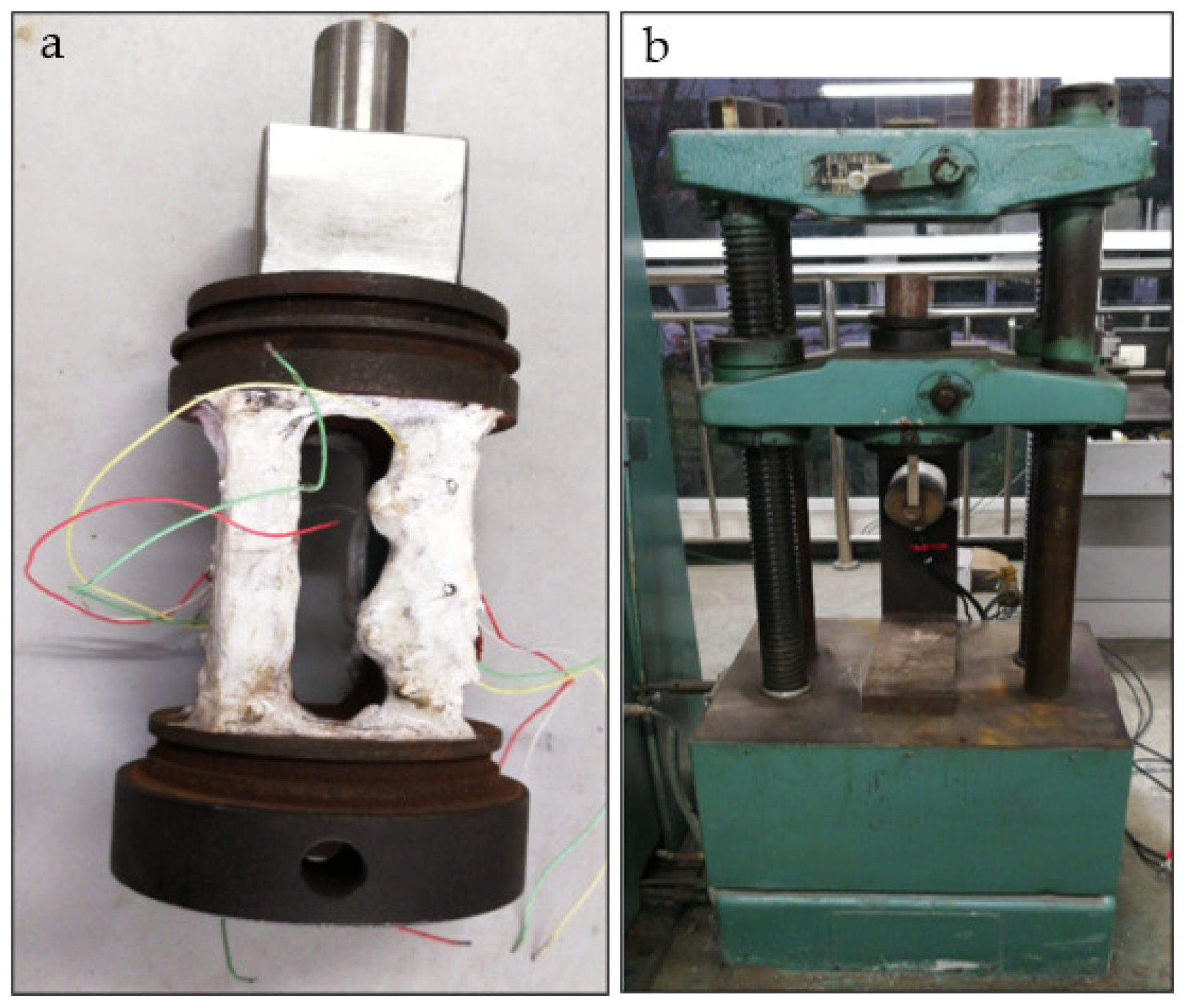
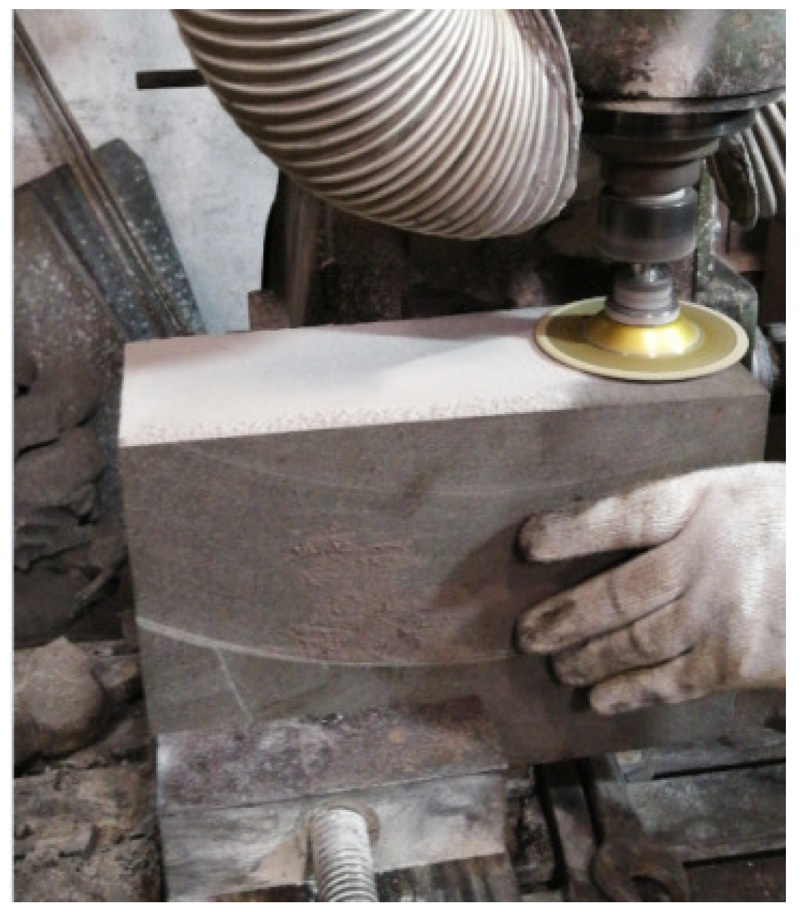
2.1. Experimental Purpose

This paper reveals the rock-breaking mechanism between the cutter and granite at high temperatures through experimentation and simulation, providing a theoretical basis for the design and application of PDC bits in high-temperature geothermal drilling and offering significant guidance for the field.
The rock-breaking efficiency of scraping granite was investigated at different temperatures. The interaction mechanism between the cutter and granite under high-temperature conditions was revealed through unit scraping experiments with various cooling methods and cutting parameters. Clarifying the load variation laws of rock fragmentation by PDC bits, cutting tooth distribution, and rock fragmentation state is of great significance for the design and optimization of PDC bits in challenging formations such as high-temperature geothermal wells.
When performing single-tooth scraping at high temperatures, the sensor used must be capable of withstanding sufficiently high temperatures. In the design of the sensor, high-temperature resistance is achieved by welding high-temperature compensation plates to the four sensor columns. The designed sensor is subjected to an aging treatment to avoid changes in internal stress caused by the manufacturing process, which may affect testing accuracy. After the aging treatment, the sensor is patched with wiring and filled with high-temperature-resistant adhesive. After filling, the sensor is calibrated. The calibration process is shown in Figure 1.
The rock sample size used in the unit scraping experiment is 300 mm × 120 mm × 120 mm and the rock samples used include sandstone, limestone, and granite. During the processing of the rock samples, the corresponding dimensions are cut out using a cutting machine and then the surfaces are polished with a grinding wheel to ensure they are flat and smooth for scraping. The processing procedure is shown in Figure 2.

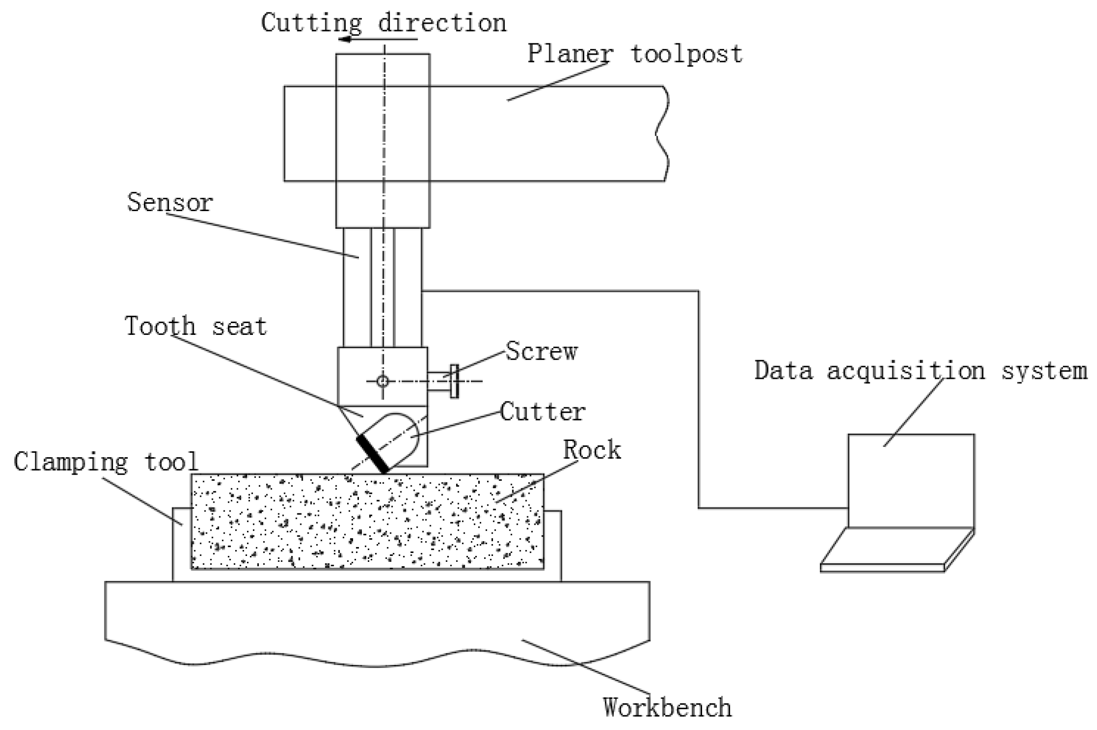
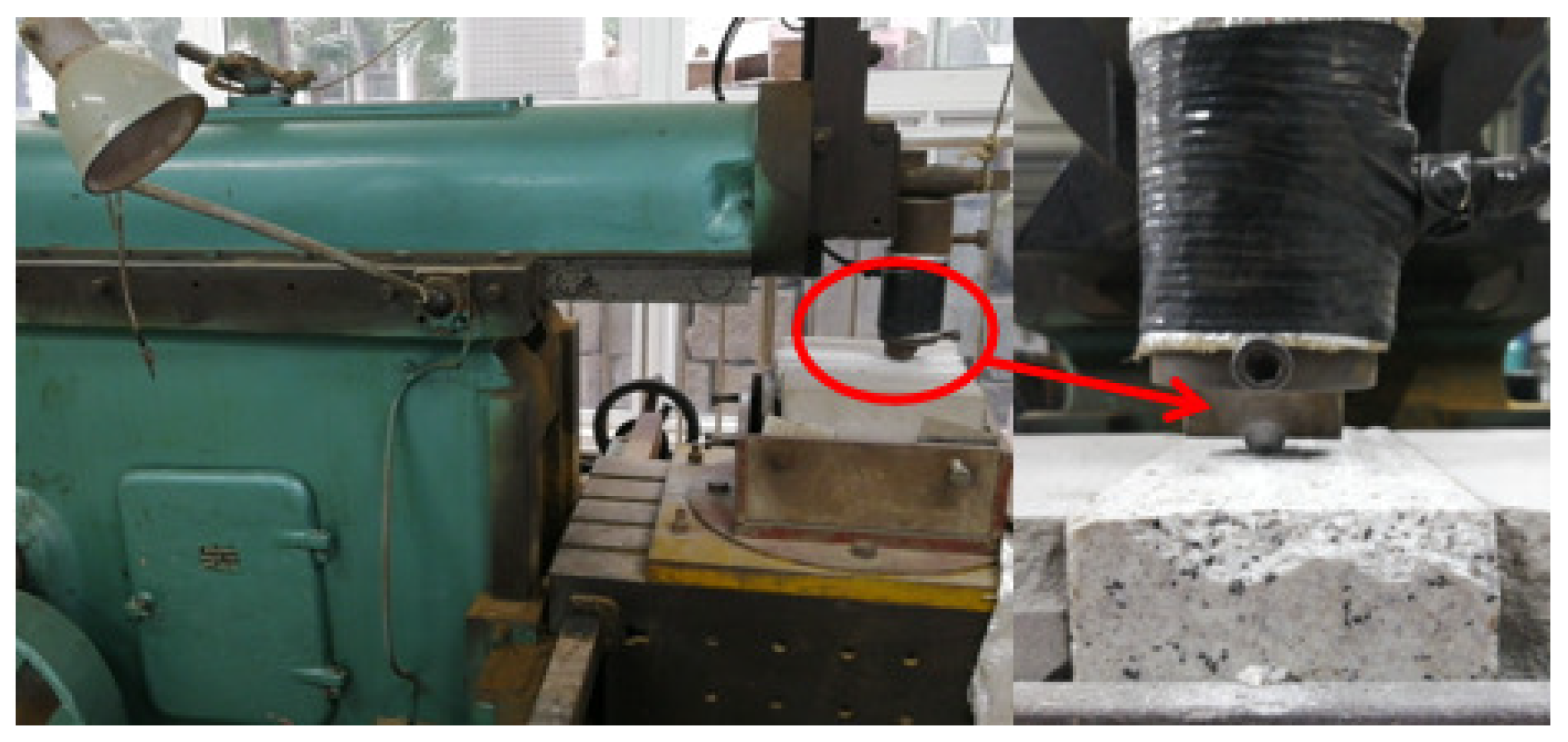
2.2. Experimental Principle and Method

The rock breaking experiment is carried out on a single cutter scraping test machine and the principle is shown in Figure 3. The equipment includes a single cutter scraping test machine, a data acquisition system, a three-dimensional force sensor, and a cutter (including tooth seats). The specific content of the experiment is as follows:
(1)
Heat rock samples of different rock types in a high-temperature heating furnace at temperatures of 100 °C, 200 °C, 300 °C, 400 °C, and 500 °C, respectively. When taking them out, wrap them with insulating materials for heat retention.
(2)
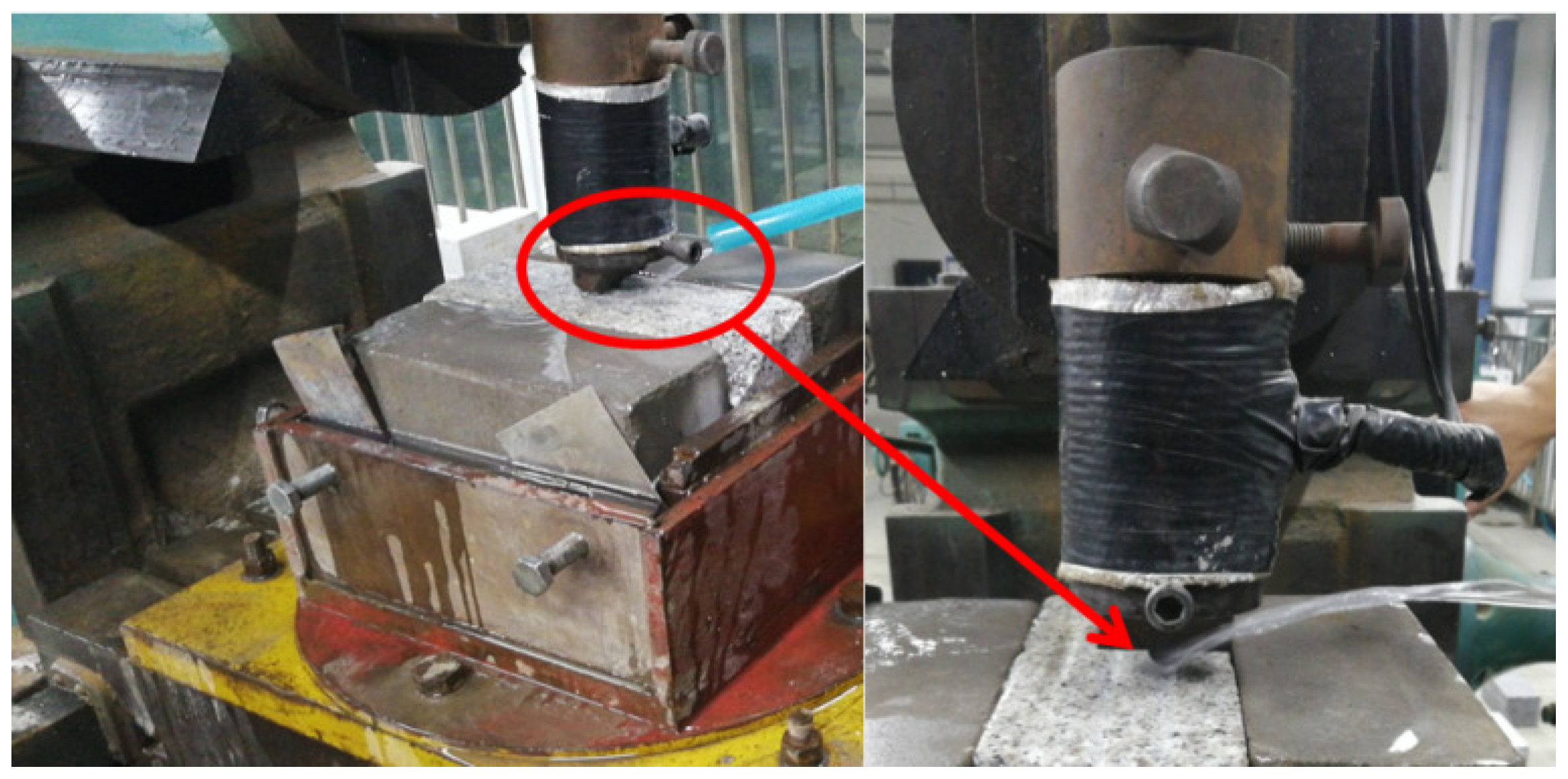
Place the heated rock on the testing machine, measure its temperature with a thermometer before scraping, and then conduct the scraping experiment;
(3)
Place the heated rock on the testing machine, cool it immediately with water, and then conduct the scraping experiment;
(4)
Cool the heated rock and place it on the testing machine for scraping and cutting experiments;
(5)
Conduct scraping experiments on rocks using cutters with different rake angles.
Before the single-tooth scraping experiment, place the rock sample in the rock clamping tool and secure it so that the scraping surface of the rock sample is parallel to the workbench. Adjust the blade holder to achieve the required scraping depth. Place the insulated rock sample on the testing machine, measure its temperature with a high-temperature gun, and then proceed with scraping and cutting. After scraping and cutting, collect the broken rock fragments.
The PDC cutter diameter is 15.875 mm, the thickness is 13 mm, and the cutting speed is 0.3 m/s. Place the thermal insulation rock sample on the test machine and measure the temperature with high temperature gun. At least 3 sets of scraping should be performed for each situation to observe any anomalies in the data and the average should be calculated based on the stability of the data; the experimental process is shown in Figure 4. The rock scraping process in the state of instant cold (liquid flow directly acts on the high-temperature rock) is shown in Figure 5.
In the process of single-tooth rock breaking, to effectively analyze the load and energy during rock breaking, the energy consumed per unit volume of broken rock (i.e., the specific energy consumed per unit volume of broken rock) is used to compare and analyze the rock breaking efficiency. The smaller the specific energy consumed per unit volume of broken rock, the less energy is consumed during cutting (relatively speaking, the more energy is saved) and the higher the rock breaking efficiency.
In the process of single-tooth scraping, under certain scraping depth conditions, the rock is mainly broken by tangential force. Therefore, the ratio of the work done by the tangential force during the scraping process to the volume of the broken rock sample is used as an indicator to measure the rock breaking efficiency at different rock temperatures.
W = i = 1 n f t i v t
The specific energy of rock fragmentation during single tooth scraping is calculated as follows:
A = W V = i = 1 n f t i v t V
where W* is the work done by the cutter, measured in Joules (J); fti is the collected discrete load data point, in Newtons (N); v is the cutting speed of the cutter, measured in meters per second (m/s); t is the cutting time, measured in seconds (s); A* is the specific energy of crushing, measured in Joules per cubic millimeter (J/mm3); and V* is the volume of rock fragmentation, measured in cubic millimeters (mm3).

2.3. Experimental Results

2.3.1. Single Cutter Scraping Results

The reliability of the experimental results was verified by averaging and analyzing the differences among the data, with a coefficient of variation of less than 1.5% for each group of data. The confidence interval was 95%, indicating that the uncertainty of the experimental results was small and verifying the accuracy of the data. The axial force, cutting force, and specific crushing work at different temperatures are shown in Figure 6. The axial force and tangential force increase first and then decrease with the temperature increase, reaching their highest values at 200 °C. When the temperature is 400 °C, the axial force and tangential force show little change. The axial force is reduced by 19–24% at 300 °C–500 °C and the tangential force is reduced by 11–16% compared with normal temperature. The specific crushing work increases first and then decreases, with a minimum value of 0.388 J/mm3. When the temperature exceeds 200 °C, rock breaking efficiency increases with the temperature rise. Compared with normal temperature, the specific crushing work is reduced by 15% at 300 °C–500 °C. The main reason is the internal heterogeneity of the rock. At different temperatures, the rock’s internal material expands when heated, causing thermal fractures. At a certain temperature, particle expansion reduces the internal gaps in the rock, enhancing the binding force between particles. More load is required for cutting due to the dense nature of granite. With increasing temperature, grain expansion occurs inside the rock. When the temperature exceeds the rock’s maximum yield strength, the internal substances expand, generating different thermal stresses at the junctions. This reduces the binding strength of the internal heterogeneous substances, allowing the rock to be broken with a smaller cutting load. When the temperature reaches a certain value, the rock’s internal expansion stabilizes and the cutting load fluctuates less. The scraped debris at different temperatures are shown in Figure 7.
The specific crushing work under self-cooling (where the rock sample is naturally cooled to room temperature) and instant cooling (where liquid flow directly acts on the high-temperature rock) is shown in Figure 8. The specific crushing work under instant cooling is smaller than that under self-cooling, reducing by 12–25%. This indicates that the rock breaking efficiency of the instant cooling mode is higher than that of the self-cooling mode at the same temperature. Under self-cooling, the specific crushing work increases first and then decreases, with a maximum value of 0.412 J/mm3 at 200 °C and a minimum value of 0.318 J/mm3 at 500 °C. Under instant cooling, the specific crushing work gradually decreases, with a minimum value of 0.267 J/mm3 at 500 °C, where the rock breaking efficiency is the highest. The main reason is that under self-cooling, the rock’s internal bonding force increases within a certain temperature range. As the temperature decreases, the swollen particles in the rock contract due to cooling. However, these particles cannot fully recover to their pre-heated state, which reduces the bonding force and internal particle strength of the rock. The cooling process is relatively gradual, with little change in the temperature gradient, resulting in minimal thermal fracturing of the rock. In contrast, under instant cooling, the temperature changes abruptly, causing the particle material inside the rock to shrink rapidly due to the cold. This rapid cooling generates cracks quickly. Additionally, the internal particle shrinkage is uncoordinated, which intensifies crack propagation and the generation of new cracks. This significantly reduces the rock’s strength. The cooling process in this mode is highly unstable, with a large temperature gradient change, leading to substantial thermal fracturing inside the rock.

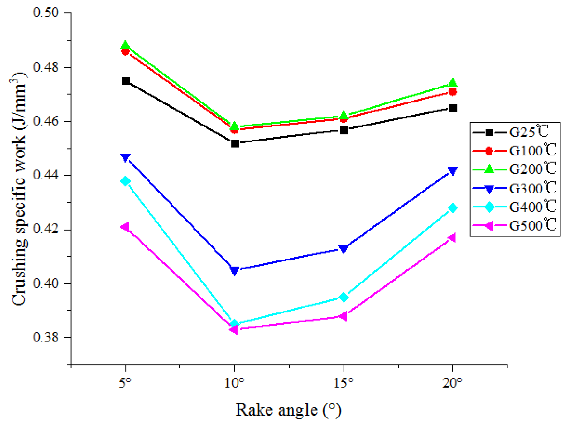
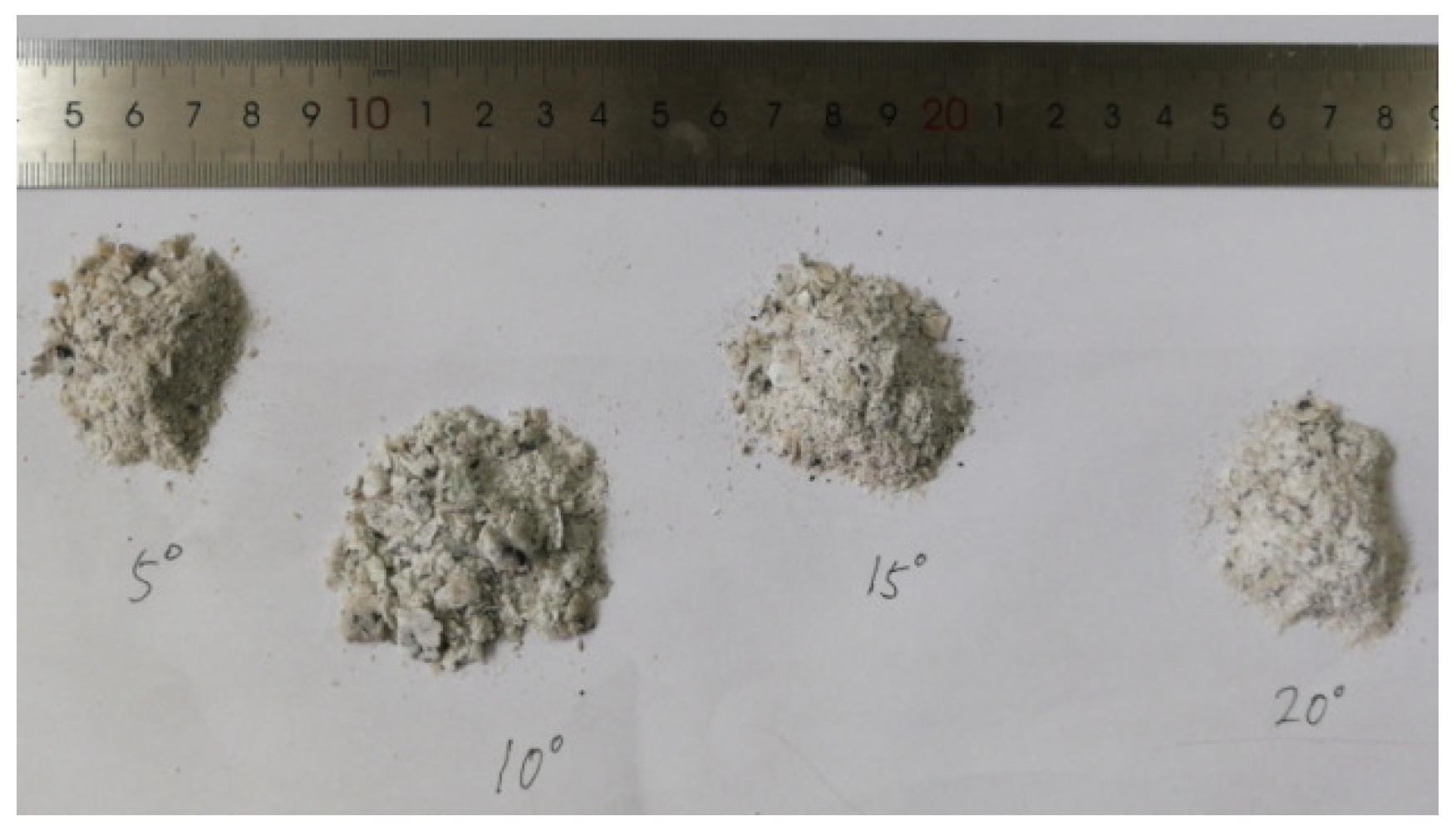
2.3.2. Single Cutter Scraping Results with Different Rake Angles

The reliability of the experimental results was verified by averaging and analyzing the differences of different data, with a coefficient of variation of less than 1.4% for each group of data. The confidence interval was 95%, indicating that the uncertainty of the experimental results was small and verifying the accuracy of the data. The specific crushing work under different rake angles is shown in Figure 9. When the temperature is constant, the specific crushing work decreases first and then increases with the increase of the rake angle. When the rake angle is 10°, the minimum specific crushing work values are 0.452 J/mm3, 0.457 J/mm3, 0.458 J/mm3, 0.405 J/mm3, 0.385 J/mm3, and 0.383 J/mm3, respectively. That is, the crushing efficiency is the highest under this rake angle. When the rake angle is constant, the specific crushing work is the largest at 200 °C; that is, the rock breaking efficiency is the lowest, with values of 0.488 J/mm3, 0.458 J/mm3, 0.462 J/mm3, and 0.474 J/mm3 at 5°, 10°, 15°, and 20° rake angles, respectively. As shown in Figure 10, the amount of debris is the largest and the debris particle size is the largest when the rake angle is 10°.

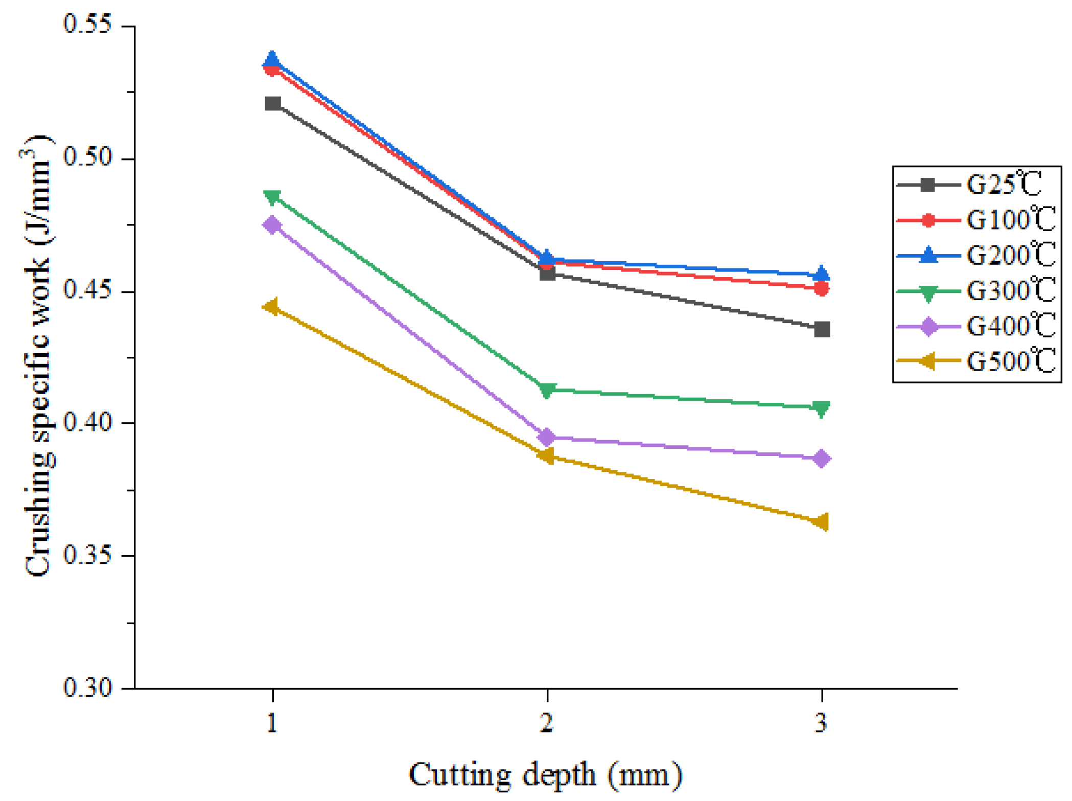
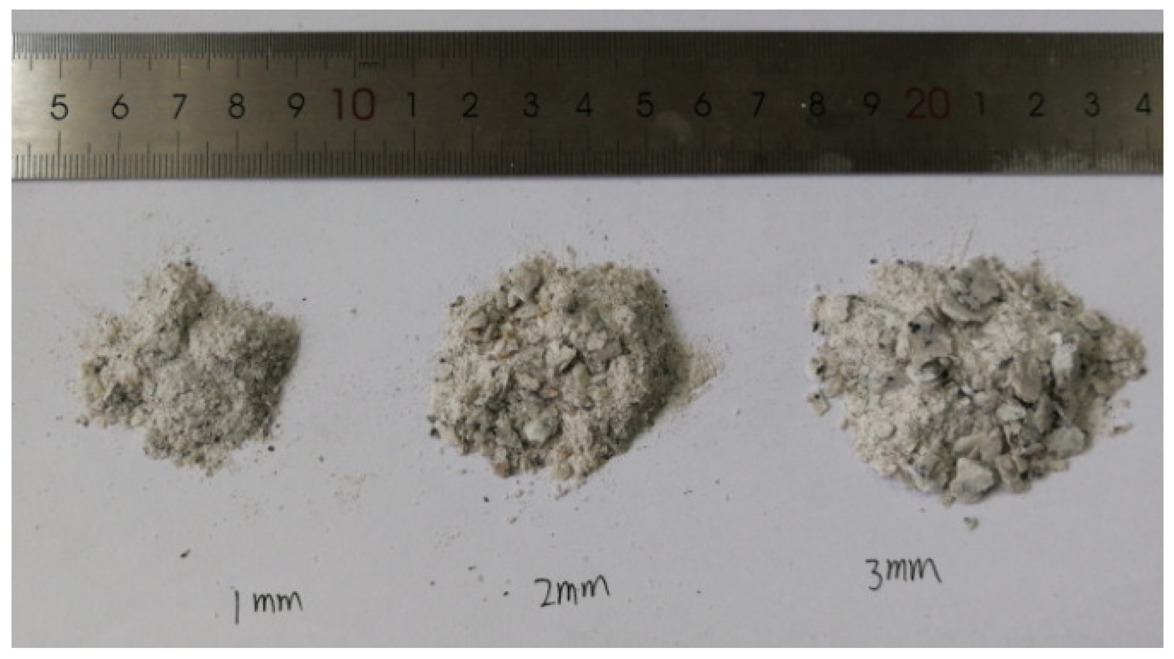
2.3.3. The Single Cutter Scraping Results with Different Cutting Depth

The reliability of the experimental results was verified by averaging and analyzing the differences of different data, with a coefficient of variation of less than 1.55% for each group of data. The confidence interval was 95%, indicating that the uncertainty of the experimental results was small and verifying the accuracy of the data. The specific crushing work at different cutting depths is shown in Figure 11. At the same depth, the specific crushing work increases and then decreases with the temperature increase. The specific crushing work is the largest and the rock breaking efficiency is the lowest when the temperature is 200 °C. The maximum specific crushing work is 0.537 J/mm3, 0.462 J/mm3, and 0.456 J/mm3, respectively, when the cutting depth is 1 mm, 2 mm, and 3 mm. At the same temperature, the specific crushing work gradually decreases with the increase in cutting depth. When the cutting depth is 3 mm, the specific crushing work is the minimum, with minimum values of 0.436 J/mm3, 0.451 J/mm3, 0.456 J/mm3, 0.406 J/mm3, 0.387 J/mm3, and 0.363 J/mm3, respectively. The rock breaking efficiency is the highest under this cutting depth. The debris produced by different cutting depths is shown in Figure 12. With the increase in cutting depth, the debris produced also increases and the debris particle size also gets larger.
In summary, temperature changes can directly affect the internal particle bonding strength of rocks under certain conditions, which is beneficial for bit rock breaking. Moreover, reducing rock temperature under external conditions can greatly weaken rock strength and improve rock breaking efficiency. When the rake angle of the cutter is 10°, the amount of rock debris generated is the highest and the particle size of the rock debris is the largest, which has a good effect on improving the efficiency of rock fragmentation. The depth of penetration can greatly improve the efficiency of rock fragmentation. If the drilling parameters allow, the depth of the cutter can be used to improve rock fragmentation. Therefore, when designing the PDC bit, reducing the cooling efficiency of the rock under cold conditions through the design of water holes, while using a 10° rake angle and increasing the depth of the cutter, can greatly improve the rock breaking efficiency of the PDC bit and reduce drilling costs.

3. Numerical Simulation

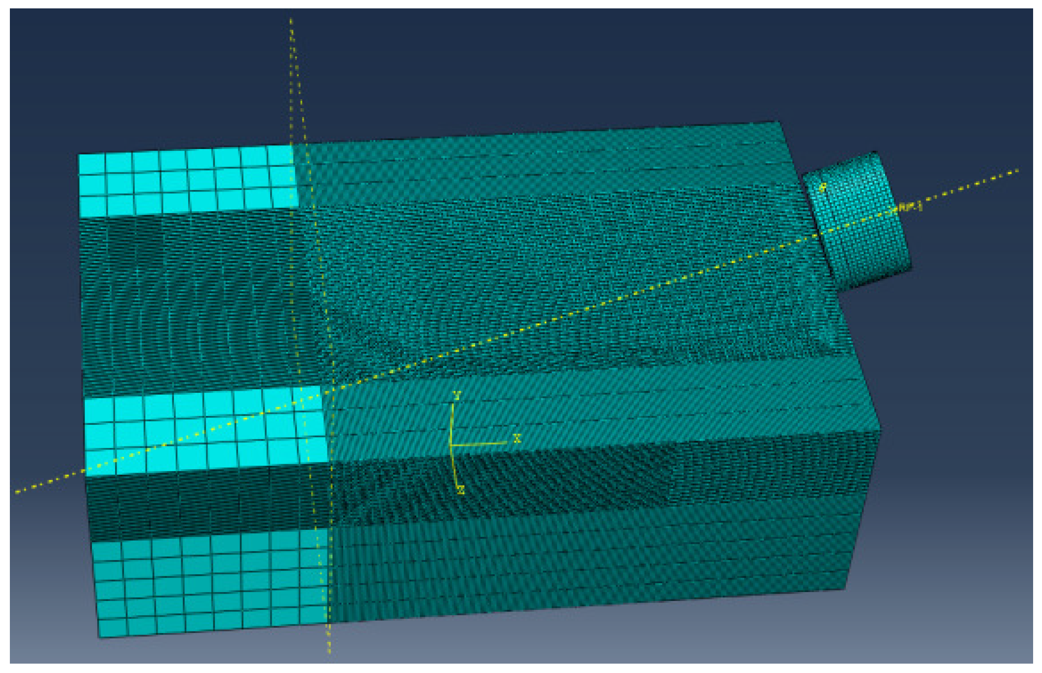
3.1. Finite Element Model

For the plastic constitutive relationship of rock materials, this article chooses the Drucker–Prager strength criterion applicable to granular materials. This criterion not only considers the influence of intermediate principal stress on failure characteristics but also reflects the shear dilation effect caused by yielding. This model is widely used in rock fragmentation processes. The Drucker–Prager criterion is represented by the normal stress and shear stress on a regular octahedron.
τ o c t = τ 0 + m σ o c t
τ o c t = 1 3 ( σ 1 σ 2 ) 2 + ( σ 2 σ 3 ) 2 + ( σ 3 σ 1 ) 2 σ o c t = 1 3 ( σ 1 + σ 2 + σ 3 ) m = 6 α ,   τ 0 = 6 3 k
α = 2 sin φ 3 ( 3 sin φ )
k = 6 c cos φ 3 ( 3 sin φ )
σ1, σ2, and σ3 are the principal stresses of the rock and k and α are parameters related to the cohesion c and internal friction angle φ.
For the convenience of calculation and analysis, the following assumptions are made for the interaction model between the cutter and rock:
(1)
The rock is a homogeneous and continuous isotropic medium;
(2)
When the rock fails, it is immediately removed from the rock mass, ignoring its impact on subsequent drilling;
(3)
The hardness and strength of the cutter are higher than those of the rocks and there is no wear during the scraping process;
(4)
The main mode of heat transfer between the teeth and rocks is through thermal conduction, ignoring the effects of convective heat transfer and thermal radiation.
Figure 13 shows the finite element model of the single-tooth scraping process, where the rock size is 100 mm × 80 mm × 40 mm, the cutting tooth diameter is 15.875 mm, the thickness is 8 mm, the composite thickness is 2 mm, the forward inclination angle is 15°, and the backward inclination angle is 0°. The rock is discretized using a hexahedral eight-node linear reduced integral element with hourglass control (C3D8RT) and local meshing is applied to the rock. During the scraping process, a fixed constraint is applied to the bottom surface of the rock and the cutter scrapes the rock at a speed of 0.3 m/s. The scraping model temperatures are 100 °C, 200 °C, 300 °C, 400 °C, and 500 °C, respectively. This article uses the ABAQUS-2021/Explicit coupled temperature-displacement dynamic explicit analysis type for model calculation.

3.2. Simulation Results

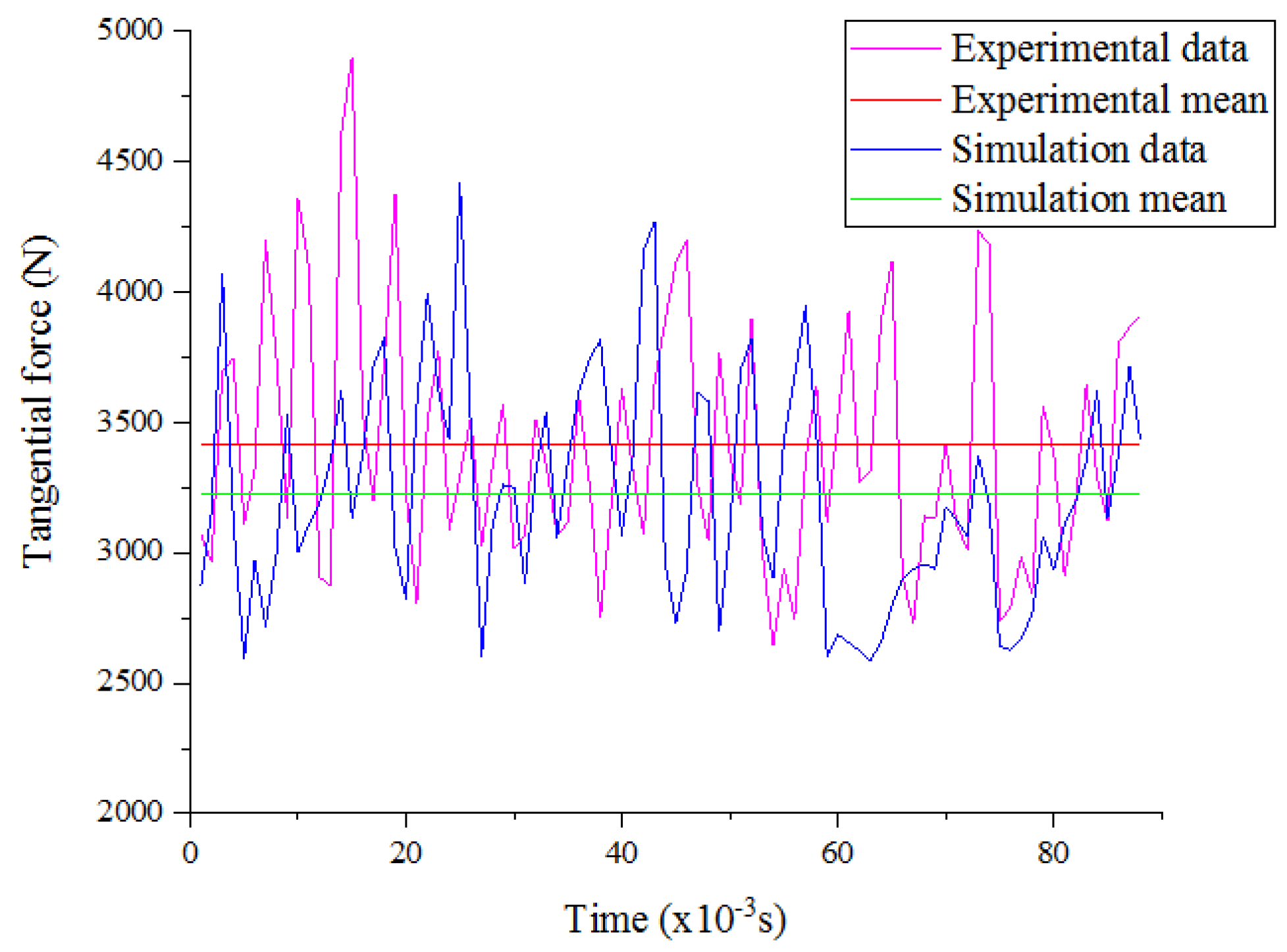
3.2.1. Model Validation

When the temperature is 300 °C, the simulation is compared with the experimental results in the stable stage, as shown in Figure 14. When cutting rocks with a cutter, the fluctuation of the load reflects the volume fragmentation of the rock unit during scraping. When the cutter interacts with the rock, the load on the cutter increases under the action of the reaction force and the load on the rock continues to accumulate. When the load reaches the critical point of rock fragmentation, damage occurs, reducing the rock’s strength and decreasing the load on the cutter. After the fragmented rock is removed, the cutter is in a state of no load for a very short period of time and the cutting force reaches its minimum. It is not until contact with subsequent rock units begins that the cutting load continues to increase. Therefore, the cutting load fluctuates continuously during rock fragmentation, and it can be seen that the overall trend of simulation and experimental fluctuations is consistent. The average cutting load in the experiment is 3412.3 N and the average cutting load in the simulation is 3226.6 N, with an error of only 5.69% between the two, thus verifying the reliability of the simulation model.

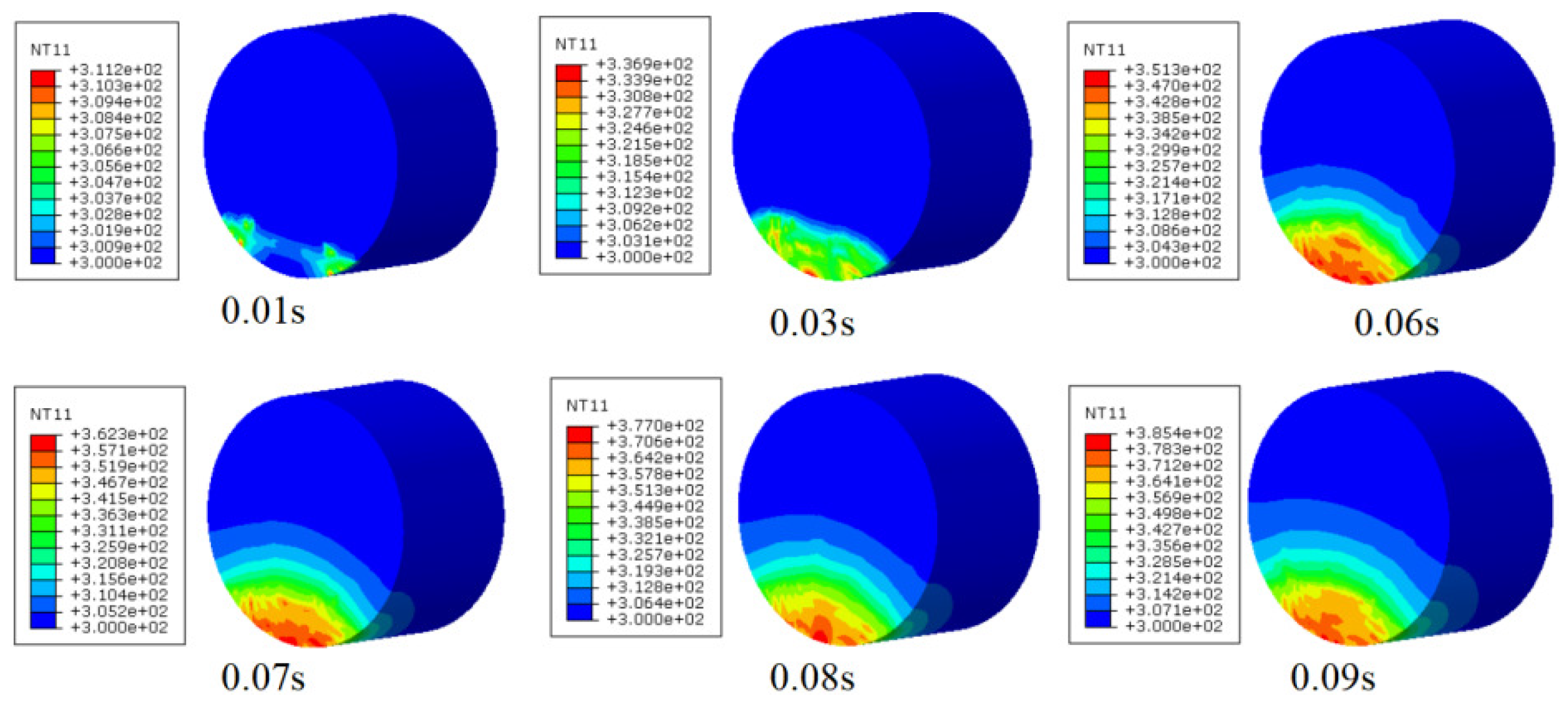
3.2.2. Study on Cutter Temperature Field

The cutter surface temperature distribution during cutter scraping of granite at different temperatures is shown in Figure 15. The area with the highest cutter surface temperature does not appear on the tooth edge but is located near the tooth edge, forming a significant “hot zone” not far from the cutter edge. The main reasons are as follows:
(1)
The cutter generates a large amount of debris and cutting heat when cutting the rock, causing the debris with a large amount of cutting heat to act on the cutter surface near the tooth edge;
(2)
The cutter surface temperature is a continuous accumulation process, with plastic deformation and friction heat generated near the cutter edge, resulting in the highest temperature near the cutter edge;
(3)
During the cutting process, the rock is squeezed and deformed and a large amount of heat generated by the deformation is transferred to the cutter, increasing the cutter surface temperature.
The cutter surface temperature cloud diagram at different times at 300 °C is shown in Figure 16. The cutter surface temperature increases continuously with the cutting time, the heat conduction phenomenon becomes more pronounced, and the temperature gradient becomes larger. The area with the highest temperature on the cutter surface is near the cutter edge, which is where rock plastic deformation and friction heat generation between the cutter and debris are concentrated. This area is also the main reason for thermal wear and thermal cracking.

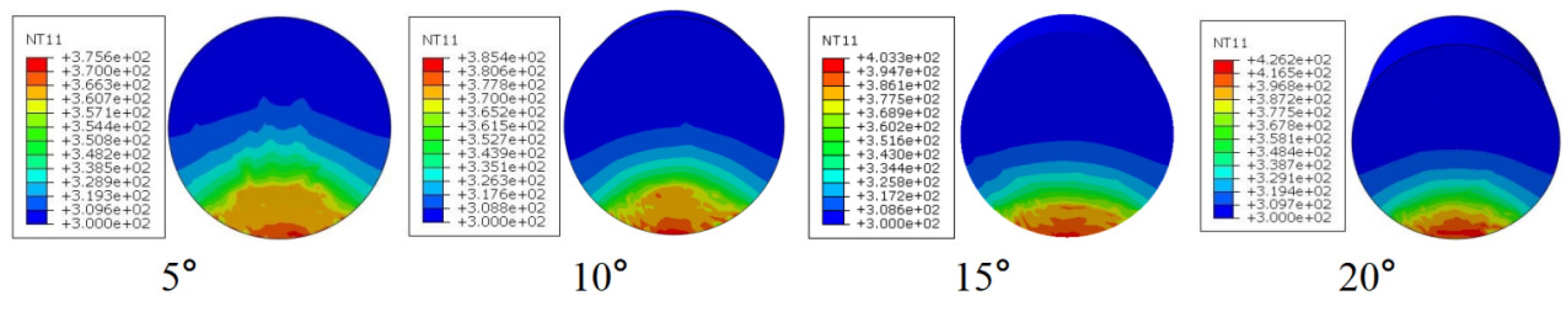
3.2.3. Study on Stress and Temperature Field of Cutter Under Different Cutting Parameters

(1)
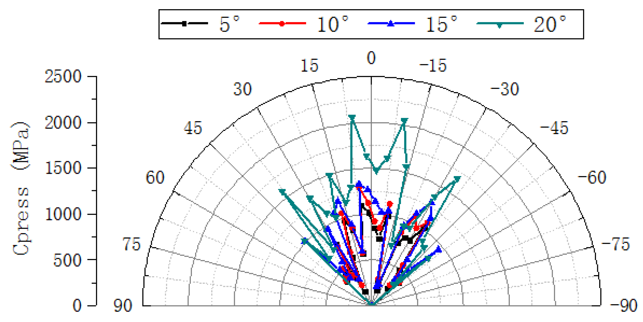
The cutter stress and temperature field distribution under different rake angles
The cutter temperature change under different rake angles is shown in Figure 17. The cutter surface temperature area gradually increases with the increase in rake angle and the high-temperature value area within the cutter edge polar angle becomes wider. The smaller the rake angle, the larger the ratio of the cutter surface temperature gradient range to the cutter surface area, and the highest temperature is located near the lowest point of the cutter edge.
The compressive stress (Cpress) of the cutter edge under different rake angles is shown in Figure 18. The cutter edge stress and stress fluctuation increase continuously with the increase in rake angle. The main reason is that the larger the rake angle, the larger the contact area with the rock, the greater the cutter edge stress fluctuation, the stronger the squeezing effect on the rock, and the higher the likelihood of causing unbalanced wear. This is not conducive to extending the cutter’s working life.
(2)
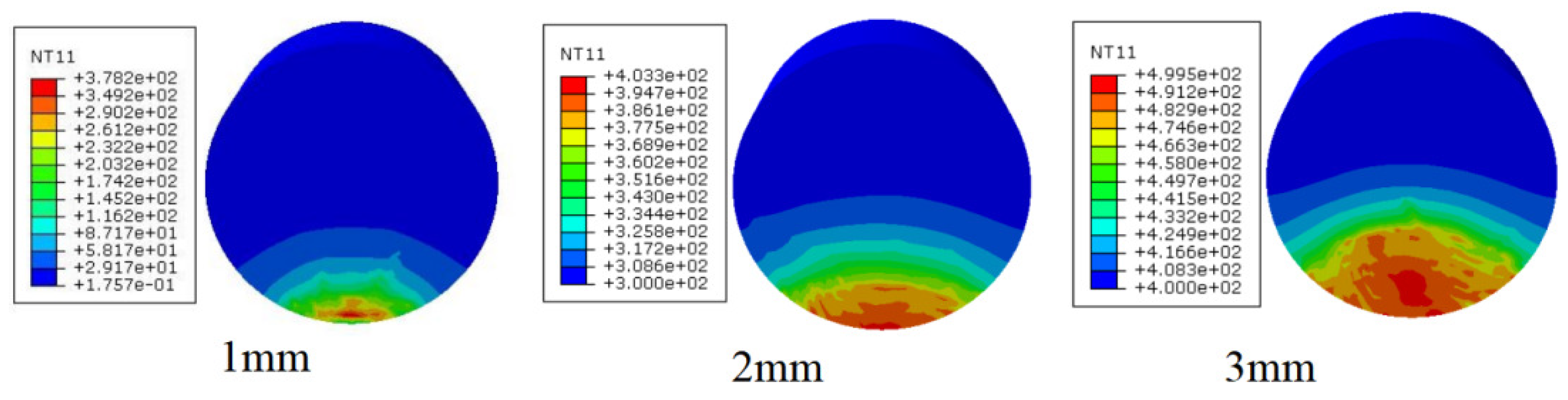
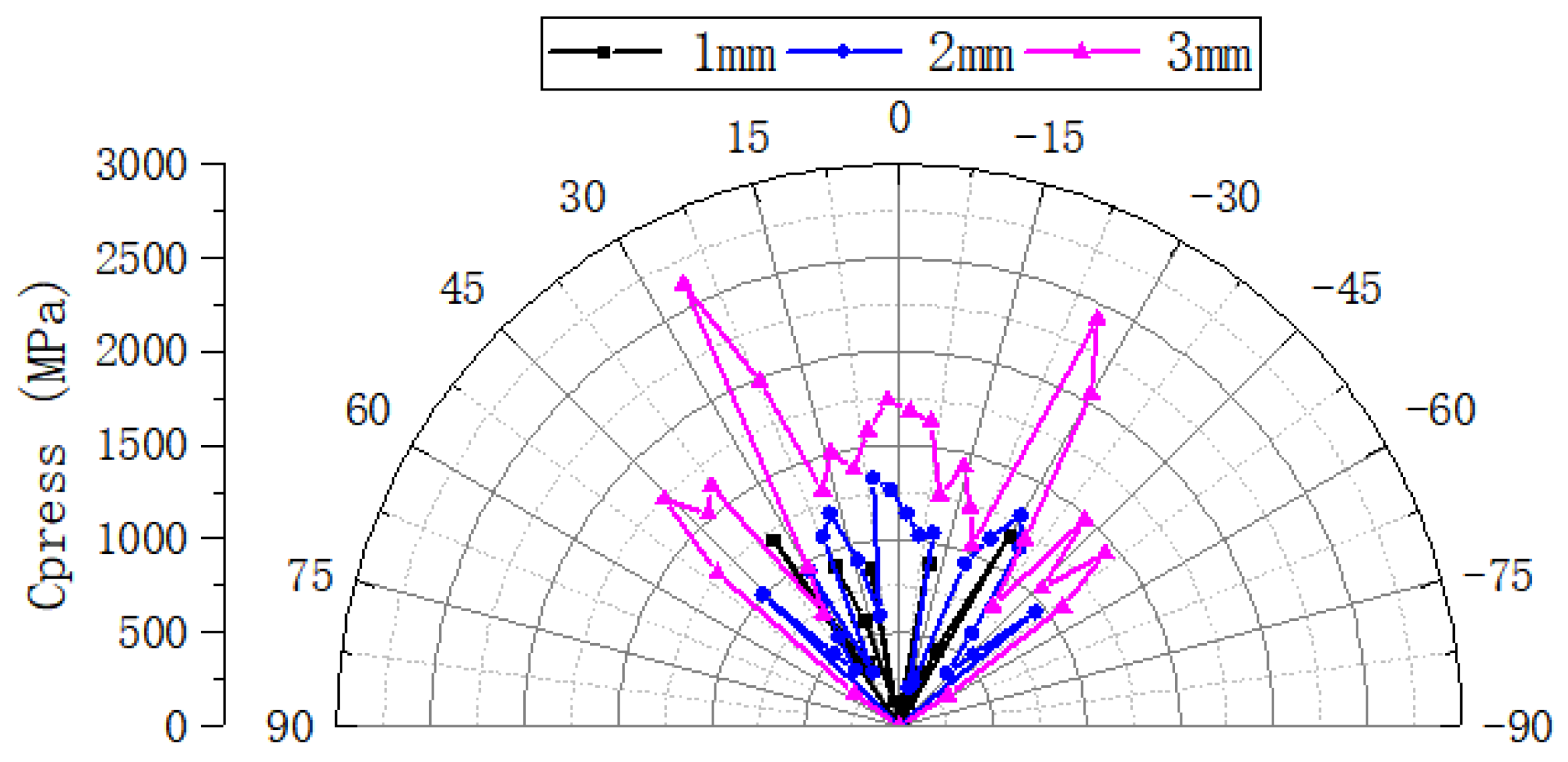
The cutter stress and temperature field distribution under different cutting depth
The cutter surface temperature distribution under different cutting depths is shown in Figure 19. The cutter surface temperature continues to increase with the increase in cutting depth. The main reason is that the rock shear surface continues to increase, the rock shear deformation increases, and the required crushing work and heat generated by friction increase, resulting in a noticeable rise in cutter temperature. The maximum cutter surface temperatures are 378.2 °C, 403.3 °C, and 499.5 °C, respectively, under different cutting depths.
The compressive stress (Cpress) distribution of the cutter under different cutting depths is shown in Figure 20. The Cpress value and contact area increase continuously with the increase in cutting depth. At different cutting depths, the contact angles between the tooth edge and the rock are 30°, 50°, and 58°, respectively. The main reason is that the larger the depth, the larger the interaction area between the cutter and rock, the more shear surface the rock receives, the more shear deformation occurs, and the higher the required crushing work. The greater the depth, the greater the contact stress fluctuation, the higher the likelihood of causing unbalanced wear, and the less conducive it is to extending the cutter’s working life.
In summary, considering the influence of rake angle on rock breaking efficiency and the variation of surface temperature during rock fragmentation, a 10° rake angle can be chosen without selecting the tooth surface inclination angle. This plays an important role in improving rock breaking efficiency and reducing tooth surface temperature. Considering that increasing the depth of penetration can cause uneven wear of the cutter, in order to improve rock fragmentation, the depth of penetration can be optimized through drilling parameter selection within the allowable drilling parameters. The difference in Cpress variation between a cutter at a 2 mm penetration depth and 1 mm penetration depth is small. Under certain conditions, the drilling parameters can be controlled to achieve a penetration depth of 2 mm to improve the rock breaking efficiency and working life of the PDC bit.

4. Conclusions

(1)
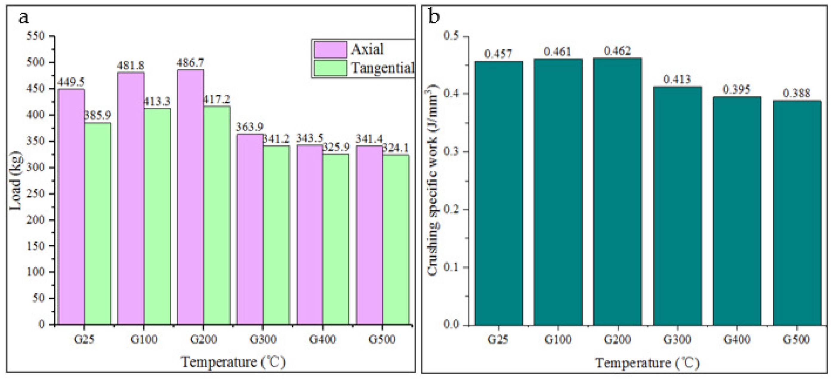
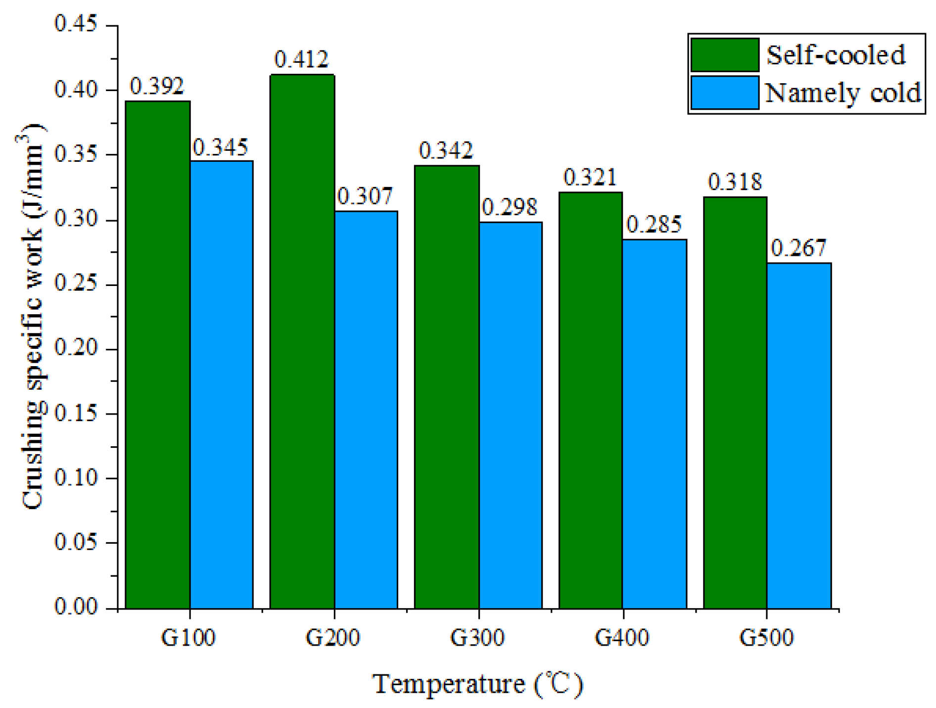
After exceeding a temperature of 300 °C, the specific energy consumption of rock fragmentation decreased by about 15% compared to room temperature, the axial force decreased by about 19–24%, and the tangential force decreased by about 11–16%. The specific energy consumption of rock fragmentation using the instant cooling method is about 12–25% lower than that of the self-cooling method and the rock fragmentation efficiency of the instant cooling method is higher than that of the self-cooling method. By designing water holes to reduce the cooling efficiency of rocks under immediate cooling, the strength of rocks can be reduced, further improving rock breaking efficiency.
(2)
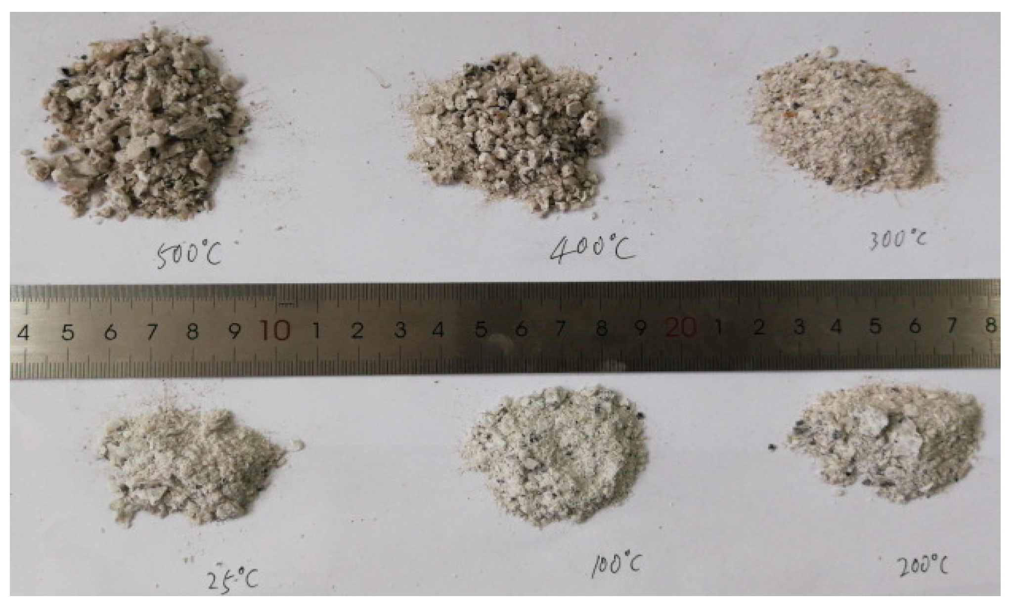
As the rake angle of the tool increases, the specific energy consumption for crushing rocks first decreases and then increases. When the rake angle of the tool is 10°, the specific energy consumption for crushing rocks is minimized, the amount of rock debris produced is the highest, and the particle size of the debris is the largest. Therefore, it is recommended to design the rake angle of the tool at 10° to improve the rock breaking efficiency of the cutter.
(3)
Considering that increasing the depth of penetration can cause uneven wear of the cutter, in order to improve rock fragmentation, within the allowable drilling parameters, the drilling parameters can be controlled to achieve a penetration depth of 2 mm to improve the rock breaking efficiency and working life of the bit.

Author Contributions

Y.Y. (Yan Yang): Writing—review and editing, Writing—original draft, Methodology, Investigation, Formal analysis. D.S.: Writing—review and editing, Writing—original draft, Visualization, Validation, Methodology, Investigation, Formal analysis. K.H. and Y.Y. (Yingxin Yang): Writing—review and editing, Writing—original draft, Visualization, Methodology, Formal analysis. H.R. and S.Q.: Writing—review and editing, Supervision, Methodology, Formal analysis. Z.H.: Writing—review and editing, Supervision, Methodology, Formal analysis, Experiment. All authors have read and agreed to the published version of the manuscript.

Funding

This study was supported by Open Fund (PLN202426) of State Key Laboratory of Oil and Gas Reservoir Geology and Exploitation (Southwest Petroleum University), Open Fund (OGE202303-19) of Key Laboratory of Oil & Gas Equipment, Ministry of Education (Southwest Petroleum University), and the “Sailing” Program for High-level Talents of Yibin University (2022QH19).

Data Availability Statement

The original contributions presented in this study are included in the article.

Conflicts of Interest

D.S. was employed by CNPC Chuanqing Drilling Engineering Co., Ltd. and Chuanxi Drilling Company. The remaining authors declare that the research was conducted in the absence of any commercial or financial relationships that could be construed as a potential conflict of interest.

References

  1. Hu, S.K.; Tian, F.; Li, H.; Cave, Q.; Guo, J.; Chun, H.D.; Zhang, Z.; Yu, H. Development and application of high efficiency wear-resistant PDC bits for ultra-high temperature geothermal drilling. Drill. Prod. Technol. 2010, 43, 1–3+141. [Google Scholar]
  2. Yang, Y.; Song, D.; Ren, H.; Huang, K.; Zuo, L. Study of a new impregnated diamond bit for drilling in complex, highly abrasive formation. J. Pet. Sci. Eng. 2019, 187, 106831. [Google Scholar] [CrossRef]
  3. Saito, S. Study on the durability of high temperature geothermal well bit. Transl. Prospect. Eng. 1997, 4, 57–62. [Google Scholar]
  4. Lukawski, M.Z.; Silverman, R.L.; Tester, J.W. Uncertainty analysis of geothermal well drilling and completion costs. Geothermics 2016, 64, 382–391. [Google Scholar] [CrossRef]
  5. Han, L. Preparation and Performance Research of High Thermal Stability Diamond Compact; Jilin University: Changchun, China, 2015. [Google Scholar]
  6. Ma, D.K. Working Mechanics of Roller Cone Bit, 2nd ed.; Petroleum Industry Press: Beijing, China, 2009. [Google Scholar]
  7. Song, D.; Ren, Z.; Yang, Y.; Chen, Y.; Nie, G.; Tan, L.; Peng, H.; Li, Z.; Chen, X.; Li, M.; et al. Drilling performance analysis of impregnated micro bit. Mech. Sci. 2022, 13, 867–875. [Google Scholar] [CrossRef]
  8. Frolova, J.V.; Ladygin, V.M.; Rychagov, S.N. Petrophysical alteration of volcanic rocks in hydrothermal systems of the kuril-kamchatla Island Arc. In Proceedings of the World Geothermal Congress, Nusa Dua, Indonesia, 25–30 April 2010. [Google Scholar]
  9. Simone, O.; Enel, I.; Regillion, K. New HT/HP Technology for Geothermal Application Significantly Increases On-Bottom Drilling Hours; SPE: Richardson, TX, USA, 2012; pp. 1–20. [Google Scholar]
  10. Song, D.D. Development and Application of PDC Bit for High Temperature Geothermal Drilling; Southwest Petroleum University: Chengdu, China, 2017. [Google Scholar]
  11. Denney, D. Technology applications. JPT 2009, 61, 22–27. [Google Scholar]
  12. Guang, X.J.; Wang, M.S.; Si, N.; Ye, H. Technical difficulties and Countermeasures of high temperature geothermal high efficiency development drilling. In Proceedings of the 18th National Exploration Engineering (Geotechnical Drilling Engineering) Technology Academic Exchange Annual Meeting, Harbin, China, 25 August 2015. [Google Scholar]
  13. Zuo, R.Q. Overview of international oil and gas well bit progress (III)-PDC bit development process and current situation (Part I). Explor. Eng. 2016, 43, 1–8. [Google Scholar]
  14. Zuo, R.Q. Overview of international oil and gas well bit development (IV)-PDC bit development process and current situation (Part II). Prospect. Eng. (Geotech. Drill. Eng.) 2016, 4, 40–48. [Google Scholar]
  15. Scott, D. A bit of history: Overcoming early setbacks, PDC bits now drill 90%-plus of worldwide footage. In Drilling Contractor Anthology Series—PDC Drilling Bits; IADC: Houston, TX, USA, 2015; pp. 1–7. [Google Scholar]
  16. Yang, Y.; Song, D.; Chen, H.; Chen, X.; Chen, L. The research on the fixation strength of tapered cone bit teeth. Eng. Fail. Anal. 2021, 124, 105318. [Google Scholar] [CrossRef]
  17. Zhou, D.Y.; Wang, R.H. Experimental study on rock abrasivity of PDC bit. J. Univ. Pet. (Nat. Sci. Ed.) 2003, 2, 41–43+7–6. [Google Scholar]
  18. Wu, Z.B.; Lv, L.T.; Wang, Y.Y. Rock breaking characteristics and temperature field change of cone PDC hybrid bit. Nat. Gas Ind. 2020, 40, 99–106. [Google Scholar]
  19. Luo, M.; Zhu, H.Y.; Liu, Q.Y. A v-tooth PDC bit suitable for ultra-high temperature and ultra-high pressure plastic mudstone. Nat. Gas Ind. 2021, 41, 97–106. [Google Scholar]
  20. Chen, L.F. “Drilling” depth and heat. China Min. News 2015, 7, 11. [Google Scholar]
  21. Shulyupin, A.N. Steamwater flow instability in geothermal wells. Thermo-Phys. Aeromechanics 2015, 22, 475–480. [Google Scholar] [CrossRef]
  22. Bill, R.; Abraham, S.; Paul, S. Successfully applying micronized cellulose to minimize lost circulation on the PUNA geothermal venture wells. In Proceedings of the Geothermal Re-Source Council, 34th Annual Meeting, Reno, NV, USA, 15–19 February 2021; pp. 1–15. [Google Scholar]
  23. Al-Shayea, N.A.; Khan, K.; Abduljauwad, S.N. Effects of confining pressure and temperature on mixed mode(Ⅰ-Ⅱ) fracture toughness of a lime-stone rock. Int. J. Rock Mech. Min. Sci. 2000, 37, 629–643. [Google Scholar] [CrossRef]
  24. Liu, Q.S.; Xu, X.C. Damage analysis of brittle rock at high temperature. Chin. J. Rock Mech. Eng. 2000, 19, 408–411. [Google Scholar]
  25. Xu, X.-l.; Gao, F.; Shen, X.-m.; Jin, C.-h. Research on mechanical characteristics and micropore structure of granite under high-temperature. Rock Soil Mech. 2010, 31, 1752–1758. [Google Scholar]
  26. Deng, H.; Zhang, M.; Deng, T.H.; Zhang, Q. Triaxial compression test of tight sandstone under high temperature and high pressure. Pet. Nat. Gas Geol. 2017, 38, 8. [Google Scholar]
  27. Zhao, Y.S.; Wan, Z.J.; Zhang, Y.; Qu, F.; Xie, G.; Wei, X.; Ma, W. Development of a 20MN servo controlled high-temperature and high-pressure triaxial testing machine for rock masses. J. Rock Mech. Eng. 2008, 27, 1–8. [Google Scholar]
  28. Zhou, C.B.; Wan, Z.J.; Zhang, Y.; Gu, B. Experimental study on hydraulic fracturing of granite under high temperature conditions. China Min. 2017, 26, 8. [Google Scholar]
Figure 1. (a) High-temperature-resistant sensor. (b) Sensor calibration.
Energies 18 00719 g001
Figure 2. Rock sample processing.
Energies 18 00719 g002
Figure 3. Single cutter scraping principle.
Energies 18 00719 g003
Figure 4. Rock scraping process. The content indicated by the red arrow is an enlarged view of the red circle.
Energies 18 00719 g004
Figure 5. The instant cold scraping rock process. The content indicated by the red arrow is an enlarged view of the red circle.
Energies 18 00719 g005
Figure 6. (a) Axial force and tangential force. (b) Specific crushing work.
Energies 18 00719 g006
Figure 7. The scraping debris.
Energies 18 00719 g007
Figure 8. The specific crushing work.
Energies 18 00719 g008
Figure 9. The specific crushing work with different rake angles.
Energies 18 00719 g009
Figure 10. The scraping debris.
Energies 18 00719 g010
Figure 11. The specific crushing work.
Energies 18 00719 g011
Figure 12. The scraping debris.
Energies 18 00719 g012
Figure 13. Finite element model.
Energies 18 00719 g013
Figure 14. Comparison between simulation and experiment.
Energies 18 00719 g014
Figure 15. The cutter surface temperature field distribution (°C).
Energies 18 00719 g015
Figure 16. The cutter surface temperature field distribution (°C).
Energies 18 00719 g016
Figure 17. The cutter surface temperature field (°C).
Energies 18 00719 g017
Figure 18. The Cpress stress distribution of the cutter edge.
Energies 18 00719 g018
Figure 19. The cutter surface temperature field (°C).
Energies 18 00719 g019
Figure 20. The Cpress stress distribution of the cutter edge.
Energies 18 00719 g020
Disclaimer/Publisher’s Note: The statements, opinions and data contained in all publications are solely those of the individual author(s) and contributor(s) and not of MDPI and/or the editor(s). MDPI and/or the editor(s) disclaim responsibility for any injury to people or property resulting from any ideas, methods, instructions or products referred to in the content.

