1. Introduction
In recent years, the evaluation of magnetic coupling among current-carrying wire coils has played a fundamental role in plenty of engineering applications. Relevant examples of applications include the transmitter-receiver electromagnetic (EM) sounding systems for ground exploration [
1,
2,
3,
4,
5,
6,
7,
8,
9,
10,
11], magnetic resonance imaging machines [
12,
13,
14], radio direction finding systems [
15,
16,
17,
18], diathermy and hyperthermia applicators [
19,
20,
21,
22], and wireless power transfer (WPT) systems [
23,
24,
25,
26,
27,
28,
29,
30,
31,
32]. In all of the mentioned situations, two or more circular coils are meant to work together to accomplish a given task. The final goal to be reached may be, for instance, power transmission from one electric system to another without the usage of cables, detection of shallow buried objects via electromagnetic induction, or the generation of induction heating in subcutaneous tissues for therapeutic purposes. Moreover, recent IoT applications have used arrays for transmitting power to free-moving objects [
28], which has revolutionized WPT techniques.
Regardless of the application under consideration, the flux linkage between the coils constituting the coil system is always a critical parameter to accurately predict, whether its value is to be enhanced or minimized. Improvement in mutual inductance is a prerequisite every time energy transfer is required, as the efficiency of the transmission of the magnetic link depends on the magnetic coupling strength. This is true, for instance, for devices like transformers and WPT systems capable of efficient energy transfer for charging batteries for electric vehicles. On the other hand, mutual inductance must be reduced if it is a measure of the amount of undesired inductive crosstalk, taking origin from the cooperation of several loop antennas, which must work together but independently from one another. This is the case for radio direction finding (RDF) systems [
15,
16,
17,
18], where loop antennas are arranged into arrays with the aim of locating the arrival direction of a radio signal. Moreover, inductive crosstalk issues may arise in the loop receiver arrays of magnetic resonance imaging (MRI) machines [
12,
13,
14] and in multi-leaf diathermy coils used for therapeutic heating of biological tissues [
19]. It is not uncommon for a coil system to be positioned close to a conducting half-space. In EM sounding systems, it is the ground exploration itself which requires that the source and receiving coil are located at the air-medium interface, either coaxially or at a radial distance from each other [
3]. This also occurs in diathermic therapies, where a structure composed of two or more current-carrying round coils works in close proximity to a conducting body to induce Ohmic heating in them via magnetic induction. Furthermore, in WPT systems for battery electric vehicles (BEVs), where electric power is transferred via magnetic induction from an emitter to a receiver and then delivered to a charging system, the coils operate close to the earth structure, whose presence considerably affects the magnetic coupling and the efficiency of the power transmission [
23,
24,
27,
29,
31,
33,
34].
Regardless of whether the objective is optimization of the magnetic coupling—that is, to maximize or minimize it depending on the application—or to build up the electrical circuit model equivalent to the entire system and study its performances, accurately evaluating the mutual inductance of two coils in the presence of a flat conducting ground always plays an essential role. Yet, to date, this problem has been efficiently treated only under simplified assumptions. Contributions in this direction include the quasi-static approximation presented in [
35], which holds only at low frequencies, and the solution derived in [
36], which is not prone to the limitations inherent to the operating frequency but, unfortunately, is tailored to the special case of equally sized coils made up of a single turn only. Moreover, the solution for the flux linkage in [
36] has been shown to diverge when the coils are aligned along the same axis (i.e., when the limit as the radial distance between their axes approaches zero). However, the mutual inductance of two coils positioned above conducting soil may always be evaluated through the use of numerical algorithms. Well-established approaches include the finite element method (FEM) and the quadrature rules for numerically evaluating the integral expression of the flux linkage. Yet, especially if the coils operate at the air-ground interface, these methods lack efficiency, as they are computationally intensive and time-consuming.
Given the described challenges, the present paper proposes an exact series-form expression describing the mutual inductance of two arbitrarily large multi-turn parallel pancake coils lying in close proximity to a terrestrial area. The terrestrial area is modeled as a flat, conducting half-space because of the large horizontal dimension compared with the size of the two-coil system, which makes the effects of the lateral boundaries negligible. BEV charging systems and EM sounding systems are examples of applications in this direction, as in both cases, the two-coil system works in close proximity to the ground.
The new derived expression leverages advancements in mathematical series expansions and integral transforms to overcome the limitations of previous methods for solving the same problem. The proposed formula comes from applying a purely analytical procedure to evaluation of the Fourier–Bessel transform representation for the mutual inductance of two arbitrary loops. First, the Gegenbauer addition theorem in integral form is applied to turn the Fourier–Bessel transform into a double integral containing a simpler integrand. Next, the oscillatory part of the integrand is replaced with its power series expansion, which makes it possible to rewrite the double integral as the sum of the products of two known tabulated single integrals. The applied rigorous procedure leads to expressing the flux linkage between the loops as a combination of spherical Hankel functions, with algebraic coefficients depending on the wavenumbers in the two media (air and conducting ground) as well as the radii of the loops.
Numerical experiments have been conducted to validate the efficiency and accuracy of the developed exact formulation. These include comparisons with the outcomes from established methods and solutions, like the Gaussian quadrature of a field integral, the finite-difference time-domain (FDTD) method, and the quasi-static approximation of the solution. The simulations show the proposed solution’s superior performance as per its accuracy, robustness, and computation time. The results indicate that as the truncated sum is increased in length, the accuracy of the new solution approaches the ones exhibited by the purely numerical techniques. Moreover, it is seen how highly accurate results are obtained in a significantly smaller computation time with respect to the numerical schemes. Finally, unlike the previous analytical formulations, the proposed solution holds in the quasi-static limit as well as in the non-quasi-static frequency range, regardless of the size of the coils. As a consequence, it can be used in the portions of the radio spectrum internationally reserved for industrial, scientific, and medical (ISM) purposes, ranging from few MHz up to a few hundred GHz. As an example, this model has practical implications in specific applications working in the shortwave bands, like inductive charging systems and diathermic treatments. Excellent illustrations of applications in this direction are the WPT system for electric vehicle charging presented in [
37], working at 13.56 MHz, and the multi-leaf diathermy applicators used for therapeutic heating of biological tissues described in [
20,
21,
22], which typically operate at 27.12 MHz.
2. Theory
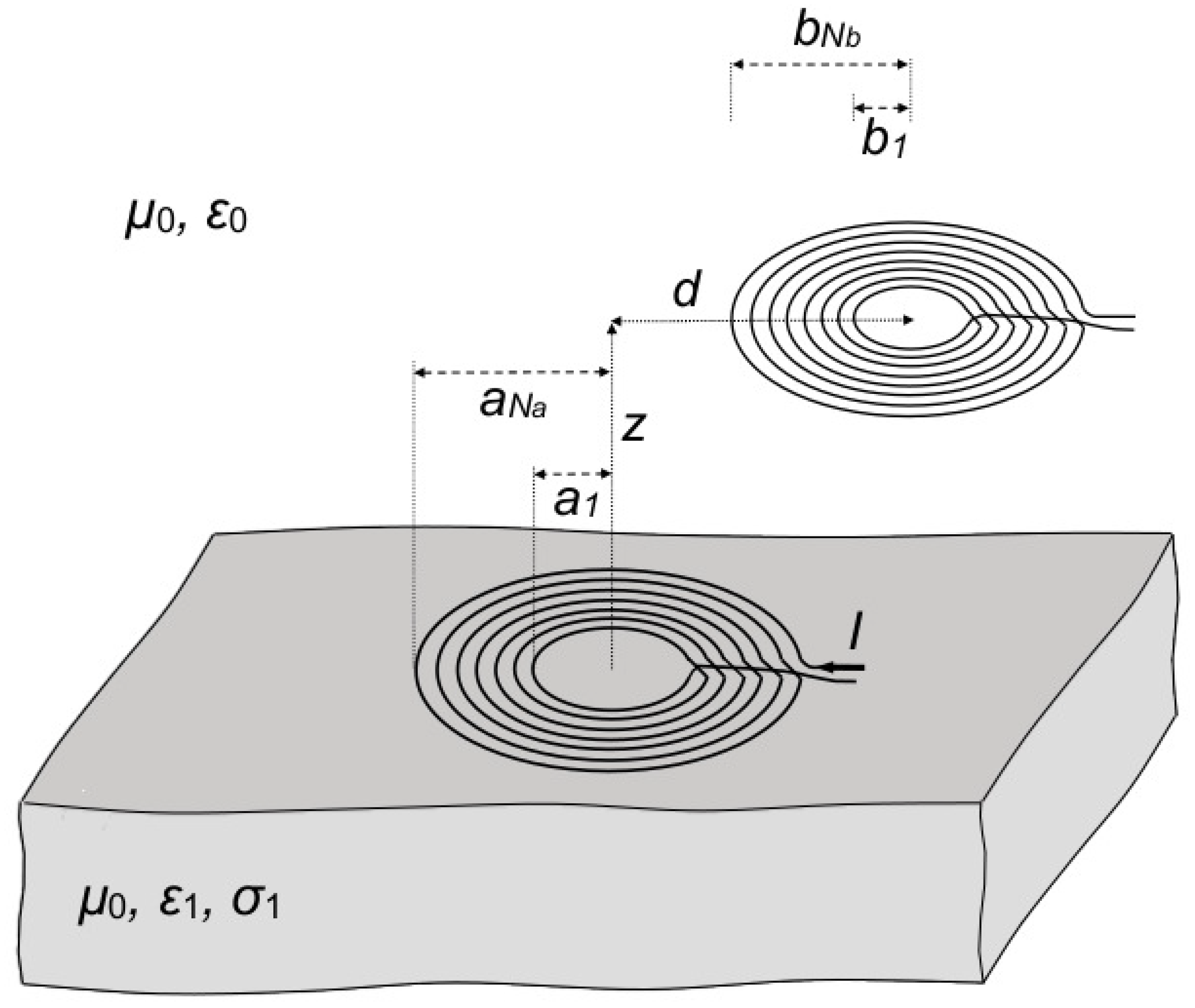
The geometry of the problem under consideration is illustrated in
Figure 1. Two non-coaxial, air-cored, thin-wire parallel pancake coils, radially apart from each other at a distance
d, are positioned above a homogeneous conducting medium. One of the coils lies at the air-medium interface, while the latter is located at a height
z from the same surface. The lower coil is made up of
turns with radii
(
), and it is assumed to carry a uniform alternating current with a phasor
I. On the other hand, the upper coil is not fed by any source and is constituted by
turns with radii
(
). The electrical conductivity and the dielectric permittivity of the air space and material medium are indicated with
and
, respectively, where
n is equal to zero or one, depending on whether it denotes the air space or the medium. Finally, the magnetic permeability is assumed to be that of the free space everywhere, which means
(
). Under these assumptions, the total magnetic flux linked with the secondary coil per 1 A of current in the primary coil may be expressed as follows:
with
being the flux linkage between two arbitrary turns belonging to distinct coils, whose radii are
a and
b.
In the present section, a rigorous analytical series-form expression for
is derived which fulfills two conditions. First, it must be valid in the quasi-static limit as well as at higher frequencies to make it possible to relax the restrictions imposed by the previous solutions. Second, it must be less computationally expensive than conventional, purely numerical procedures, like standard quadrature rules for evaluating integrals and electromagnetic simulation tools. This task is accomplished by starting from the integral describing the magnetic flux encompassed by the receiving loop [
38]:
where
is the total magnetic vector potential resulting from the primary field of the source loop plus the contribution reflected by the ground. In addition,
is the position of the generic field point
P,
C is the circumference of the receiving loop, and
is a vector element of the length along
C.
Let us introduce a polar coordinate system
centered at the axis of the emitter. With the time factor
assumed and omitted throughout the analysis, where
is the angular frequency, the time-harmonic magnetic vector potential at the generic field point
P can be written in compact form as follows [
38]:
where
is the
th-order Bessel function and
The symbols
and
r in (
3) indicate the unit vector in the
direction and the distance between an elementary current source, located at position
, and the orthogonal projection of the point
P on the plane of the emitter, denoted by
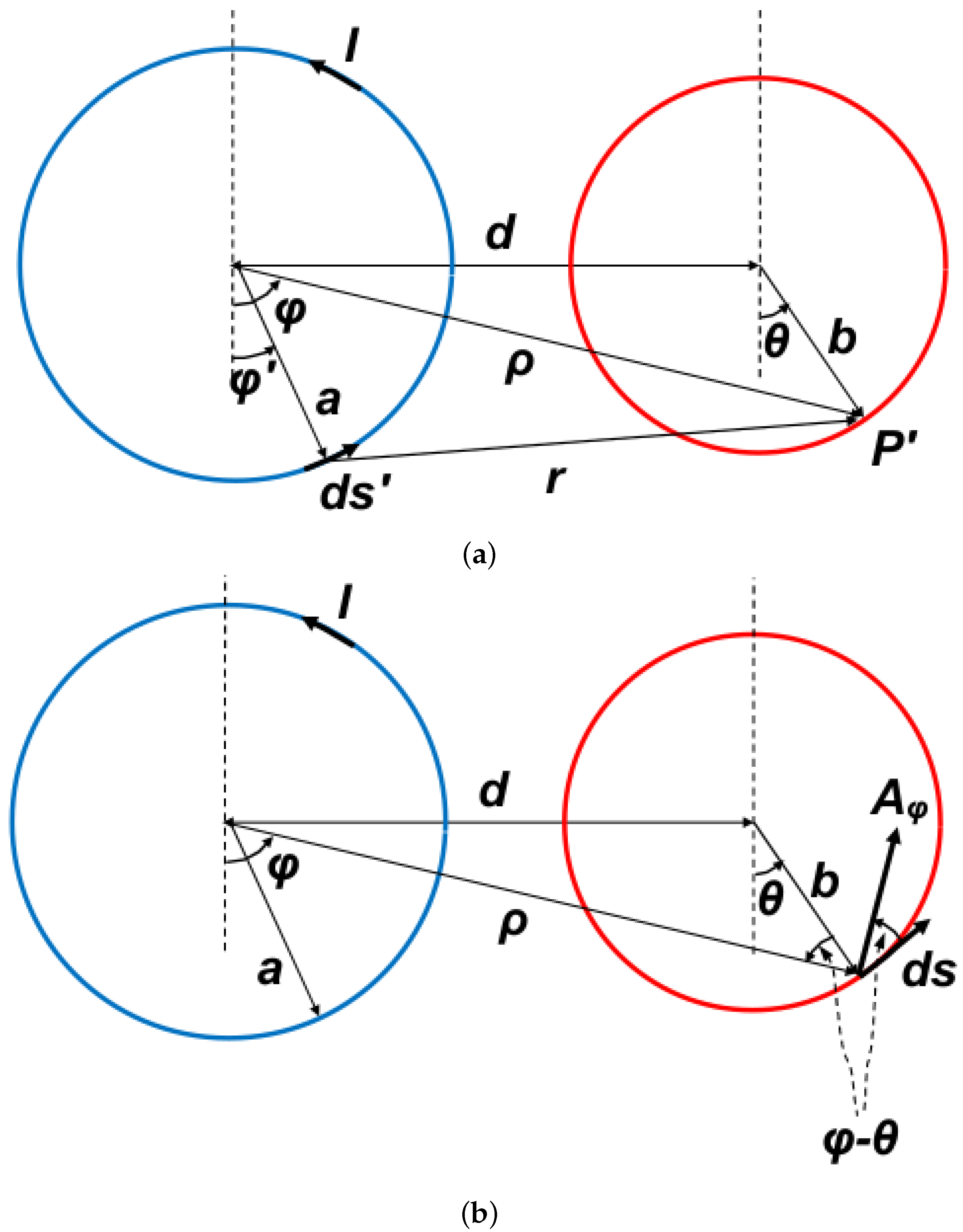
, respectively. The situation is sketched in
Figure 2a, where the source loop and the projection of the receiving loop are marked with blue and red colors, respectively. As is easily deduced, the distance between the elementary current, flowing in the vector element of a length
, and the point
is given by
It should be noted that since the field radiated by a circular loop has axial symmetry, as shown in [
38],
does not depend on
. As a consequence, it may be calculated by assuming any value for
. For simplicity, it is convenient to set
= 0 in the integrand of Equation (
3), which allows one to obtain
with
, and where the order of integration has been interchanged. Equation (
7) for the vector potential may now be converted into a single integral. Introducing the following Gegenbauer addition formula [
39] ([11.3.4])
leads to the expression
where it has been taken into account that the functions
constitute a complete orthogonal basis for piecewise
functions in the
range and that
Thus, combining Equation (
7) with Equation (
9) gives the formula
and the expression of
M in Equation (
2) assumes the form
which, after taking into account that
for any point on
C (as shown by
Figure 2b), is turned into
Equation (
14) may be further simplified by resorting to the Gegenbauer addition theorem, tailored to the Bessel function
case. Since
Figure 2b also tells us that
the addition theorem [
39] ([11.3.4]) reads
and Equation (
14) becomes
The finite integral along
in (
17) is non-null and equal to
only for
. Hence, one obtains the expression
which, under the assumption that the height
z of the receiving loop is physically as well as electrically small, simplifies to
Next, by virtue of Equation (
9), we have
where
with
and
, and Equation (
19) is converted into
To evaluate Equation (
22), it is convenient to expand
according to [
40] ([N. 9.1.10]), as follows
and then apply the identity [
40]
so as to obtain
with
It should be observed that
, which implies that the lower-order term of the sum in Equation (
25) is null. To evaluate the functions
in Equation (
27), it suffices to proceed as follows. First, the use of the formula in [
36] ([N. 17]) makes it possible to cast the semi-infinite integral in Equation (
27) in the form
with
where
is the
mth-order second-kind spherical Hankel function. Next, combining Equation (
27) with Equation (
28) and the tabulated result [
36] ([N. 25])
provides
with
being the double factorial
. Finally, according to [
36] ([N. 24]) it holds
and Equation (
31) is turned into
On the other hand, the quantities
in Equation (
26) may be evaluated by starting from expanding the
th power of Equation (
21) as follows:
This leads to write
where the integral
is easily proved to be null for even values of
h, and equal to
otherwise. Thus, upon setting
, Equation (
35) becomes
with the symbol
denoting the integer part. The use of Equations (
33) and (
37) in Equation (
25), in conjunction with Equation (
29), provides the explicit formula describing the mutual inductance; that is, we have
with
In the special case of equally sized loops
, one obtains
,
, and
where it has been taken into account that [
41] ([2.513.1])
Hence, Equation (
38) simplifies to
which is identical to the formula derived in [
36].
Finally, the small-loop approximation for
may be obtained from taking the limit of Equation (
38) as
and
, which translates into truncating the infinite sum at
l = 1. After some tedious mathematical manipulations, this yields
with
which, after simplifying, becomes
It should be observed that Equation (
38) is valid without restrictions on the operating frequency, provided that the current flowing in the primary coil can support a nearly uniform current. This can either be obtained spontaneously when the length
l of the wire constituting the coil is smaller than one third of the free space wavelength (electrically small coil) [
18] ([Ch. 5.4]) or for larger coils induced by the feeding system. In the latter case, the current in the primary coil can be made uniform by dividing it into electrically short segments, which can then be driven in parallel by means of radial transmission lines [
42,
43].
Finally, it should be also noted that the developed method can also be used for more complex coil arrangements, provided that the coils are still made up of circular turns. Once this requirement is met, Equation (
38) does not suffer from any change regardless of the geometry of the configuration. Hence, it may be still used in conjunction with Equation (
1) to determine the total mutual inductance between the coils. The only modification to be made is the replacement of
d with
in Equation (
1), which gives
This allows accounting for the fact that the radial distance between the ith turn of the emitter and the jth of the receiver ceases to be constant, unlike what happens for round coils. It is straightforward to conclude that while keeping the number of turns constant, the use of coil arrangements with more complex geometries cannot alter the computational efficiency of the method.
3. Numerical Results
The accuracy and efficiency of the derived solution was tested by comparing its outcomes with those arising from the finite-difference time-domain (FDTD) method, numerical integration of Equation (
18), and the previous solution obtained under the quasi-static field assumption [
35]. In particular, numerical integration was performed via the G7-K15 Gauss–Kronrod quadrature rule [
44]. Instead, the magneto-quasi-static solution described in [
35] comes from neglecting the high-frequency effects of the displacement currents in the air and the conducting medium, which implies that the wavelength effects are negligible. For a generic couple of turns belonging to distinct coils, with radii
b and
, the magneto-quasi-static field assumption leads to deriving the following explicit representation for the mutual inductance [
35]:
with
For the magneto-quasi-static hypothesis being met, the spatial domain must be much smaller than the free space wavelength. This implies the condition
and, as a consequence,
, with
being a characteristic dimension of the domain [
45], which is larger between
a and
b.
At first, the described approaches were applied to calculation of the real and imaginary parts of
M against the operating frequency. Two coaxial (
) three-turn coils lying on an air-medium interface were considered, with the radii of the turns being equal to
cm,
cm,
cm (transmitting coil),
cm,
cm, and
cm (receiving coil). These sizes of the turns were aligned with the design requirements of BEV charging systems [
46]. On the other hand, the medium was assumed to consist of a clay soil, with dielectric permittivity and electrical conductivity taken to be equal to
and
100 mS/m [
47,
48], respectively. The calculations were performed on a 2.3 GHz single-core machine, and the obtained results are shown in
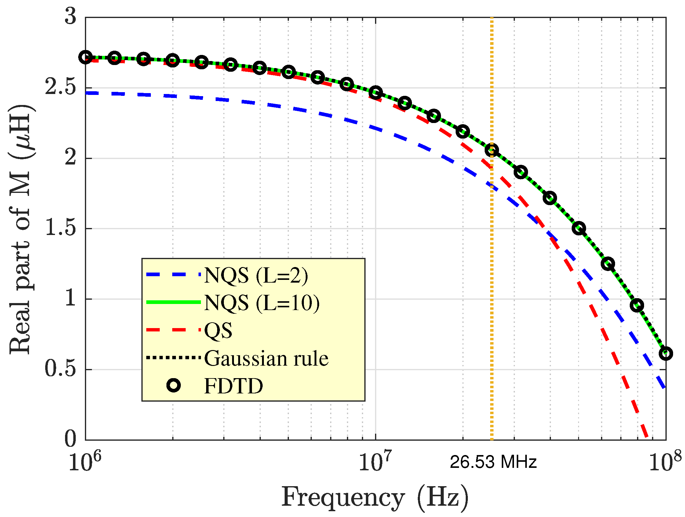
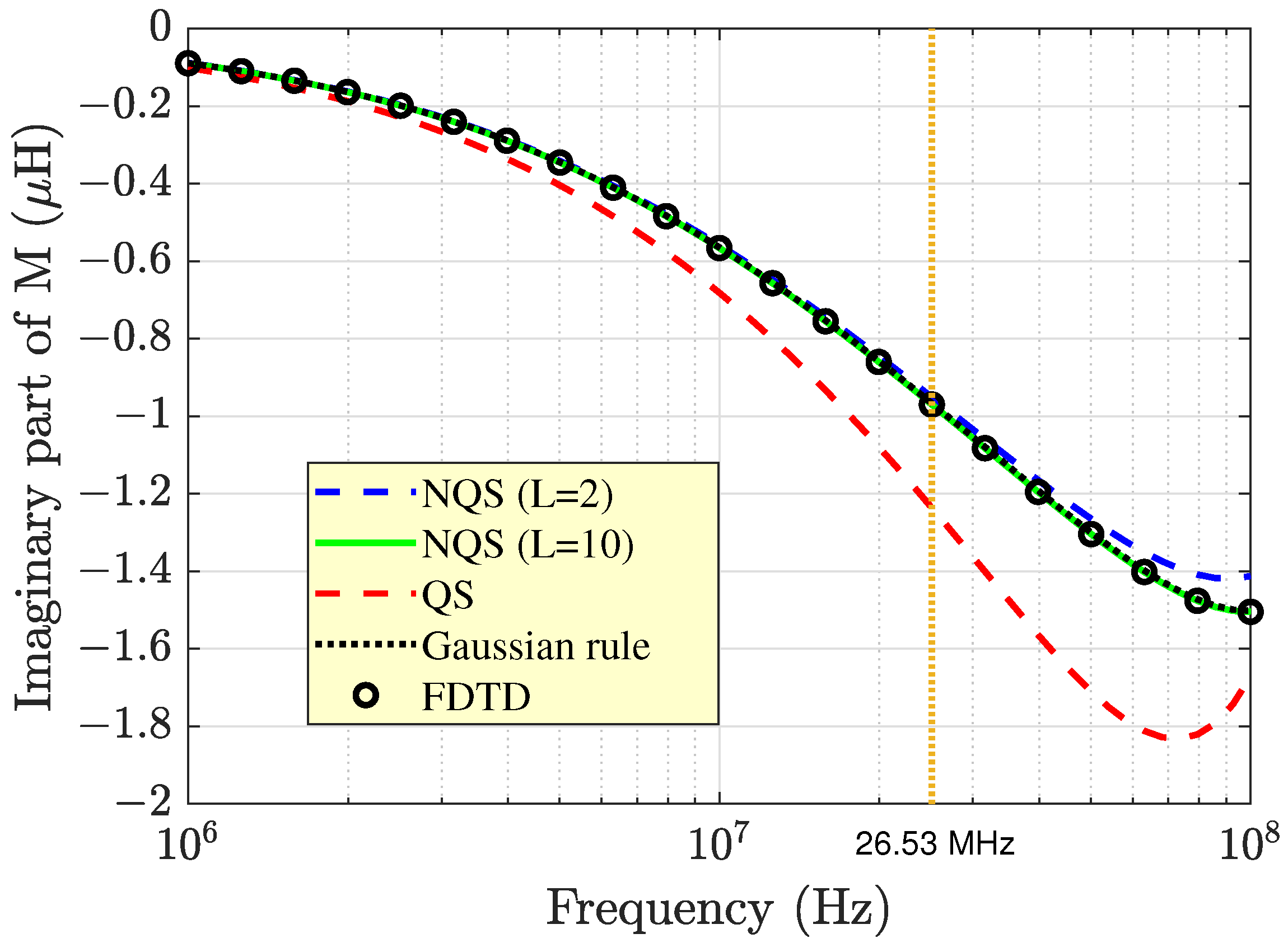
Figure 3 and
Figure 4. Here, two different curves arising from Equation (
38) are plotted, each one associated with a prescribed value for the index
L at which the series was truncated.
As can be seen, the results arising from Equation (
38) with
were in excellent agreement with those provided by the FDTD method and the G7-K15 quadrature rule, while they agreed well with the data provided by Equation (
49) only in the low-frequency range. This tells us that Equation (
38) is adequate for the generation of benchmark data and confirms that Equation (
49) can offer accurate results as long as the quasi-static approximation holds. An estimate of the theoretical upper-frequency limit of validity of Equation (
49) can be obtained from solving the inequality
for the operating frequency, with
cm. If
is used to denote the speed of light in a vacuum, then one obtains
which is the frequency region on the left-hand side of the vertical yellow line in
Figure 3 and
Figure 4. As is indicated by
Figure 3, when leaving this region, the solution to Equation (
49) could not ensure a satisfactory level of accuracy in the prediction of the real, dominant part of the inductance any longer. Conversely, as far as the imaginary part is concerned, Equation (
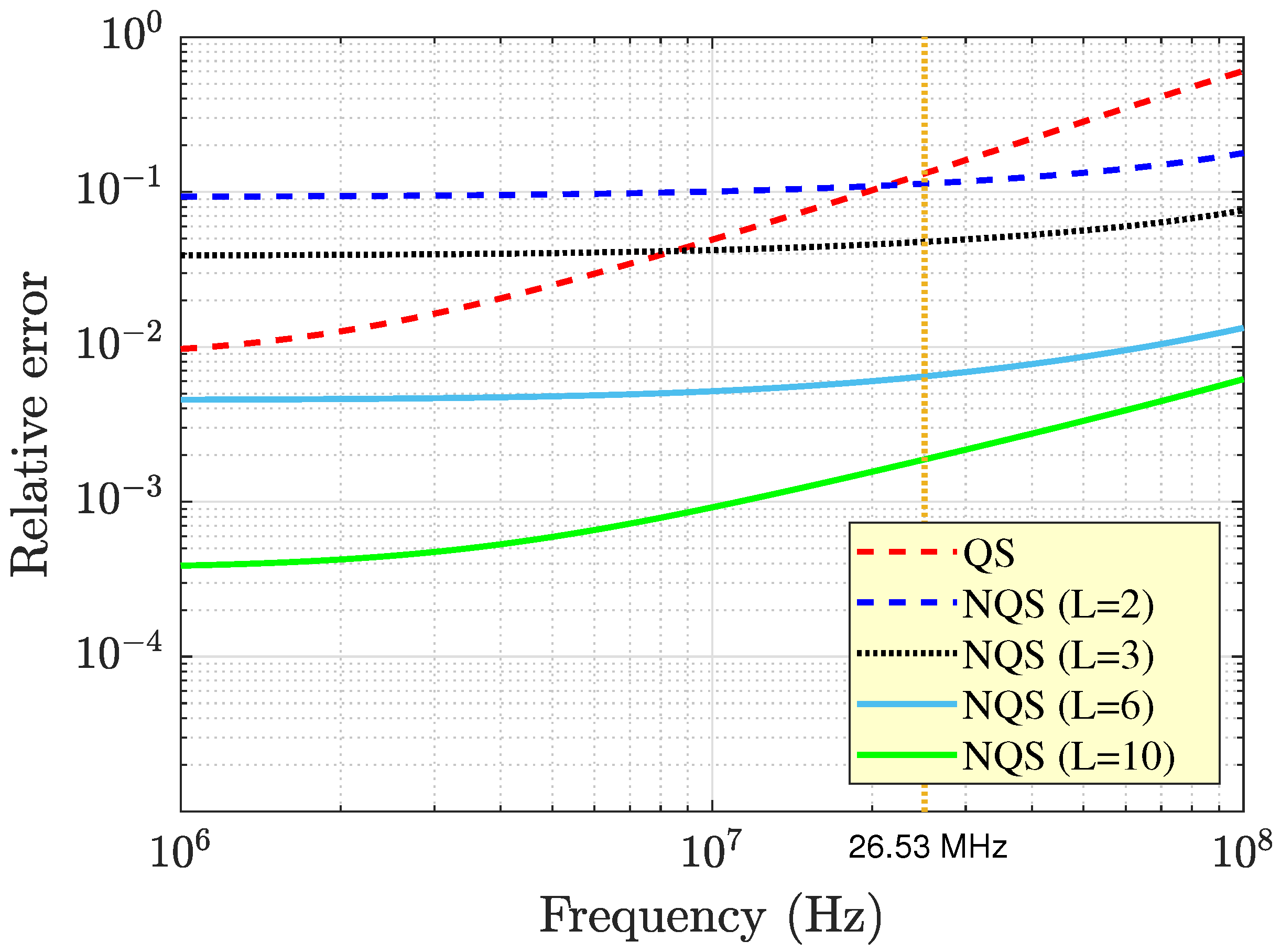
49) failed starting from frequencies below 10 MHz, which was well before reaching the theoretical quasi-static limit of 26.53 MHz. Analogous conclusions can be drawn from analysis of the curves plotted in
Figure 5, which shows the relative error of both Equations (
38) and (
49) compared with Gaussian integration of Equation (
18). As can be seen, the error of Equation (
38) was at most equal to
for
, and it was at most equal to 6 ‰ for
. This behavior of the error as
L increased confirmed convergence of the proposed solution to the exact one. On the other hand, the quasi-static expression in Equation (
49) offered acceptable performances only at frequencies lower than about 20 MHz, where the exhibited relative error was within 10%. In the same range, Equation (
49) may even outperform Equation (
38), provided that the latter is truncated at
or
. Finally, it should be noted that the relative error of Equation (
49), calculated at the theoretically computed upper frequency limit in Equation (
51) (still marked by a vertical yellow line), was slightly more than 10%, and this confirms that Equation (
51) provided a reasonable estimate of
M in the quasi-static frequency range. Thereinafter, the relative error rapidly increased, and it exceeded 60% for frequencies higher than 100 MHz.
It should be observed that, while offering the same level of accuracy as the FDTD method and the Gauss–Kronrod scheme, the proposed solution ensured substantial time savings with respect to both the FDTD method and Gaussian integration. In fact, on a 2.3 GHz PC, the use of Equation (
38) with
took about 7.21 s to calculate the curves shown in
Figure 3 and
Figure 4. Conversely, the time costs of the FDTD method and Gaussian integration were 151.41 s and 48.37 s, respectively. Thus, compared with the two numerical procedures, the speed increase exhibited by the analytical formula in Equation (
38) was at least about seven times, which implies a significantly smaller numerical complexity.
Figure 3 and
Figure 4 also point out that both the real and imaginary parts of
M exhibited a decreasing trend as the frequency increased. Yet, it should be noted that the imaginary part was negative in sign, and as a consequence, its absolute value increased. The observed profile of the real part of
M can be attributed to the fact that as the frequency increased, the effects of the displacement currents became more and more important in both the air space and the material medium, which caused propagation phenomena and oscillations to occur within the area surrounded by the receiving coil. The result was a reduction in the magnetic flux linked with the receiver.
On the other hand, the physical significance of the negative sign of the imaginary part of
M may be better understood when considering the limiting case where the source and receiving coils coincide. In such a situation, the negative imaginary part of the inductance, which will be referred to as self-inductance, gives rise to a resistive term once it is multiplied by the factor
. This term, which contributes to the loop resistance of the coil, accounts for the presence of the ground. It is, in fact, the fictitious resistance which dissipates the same average power amount as that converted into Ohmic heating in the ground. Thus, for a unit current flowing in a coil, the fictitious resistance coincides via dimension adjustment with the power loss in the ground. This correspondence provides an explanation for the behavior of the imaginary part of the inductance shown in
Figure 4. In particular, its increase in absolute value is an indication that the power loss in the ground increased as the frequency increased, and this still has yet to be connected to enhancement of the displacement currents, which makes the ground move away from good conductor behavior. In this situation, the total electric field tangential to the ground surface becomes stronger, with the consequence that the average power loss density inside the medium increases. This happens despite a reduction in the depth of penetration of the electric field into the ground. In other words, as the frequency increases, the skin depth reduction is compensated by a significant increase in the electric field strength
E in the region near the ground surface. The result is that the power loss density
increases in that region to a greater extent than it diminishes far from the surface, with the consequence that, on average, the power loss density increases.
It should be observed that enhancement of the electric field tangential to the air-ground interface is confirmed by the expression of the plane wave electric field transmission coefficient at the air-medium interface, given by [
49]
where
and
are the intrinsic impedances of the ground and free space, respectively, and
and
are the ground relative permittivity and complex relative permittivity, respectively. From Equation (
52), it follows that the amplitude of
T increases with an increasing frequency.
Furthermore, the effect of changing the electromagnetic parameters of the material medium on the magnetic coupling between the coils and the accuracy of Equation (
38) was also investigated. At first, the impact of the ground conductivity
was considered, and profiles of the real and imaginary parts of the mutual inductance against
were calculated using Equation (
38), the Gaussian quadrature rule, and the quasi-static solution in Equation (
49). The operating frequency was taken to be equal to 20 MHz, while the emitter and the receiver were assumed to be constituted by a single turn, with radii equal to
m and
m, respectively. The dielectric permittivity of the ground was equal to
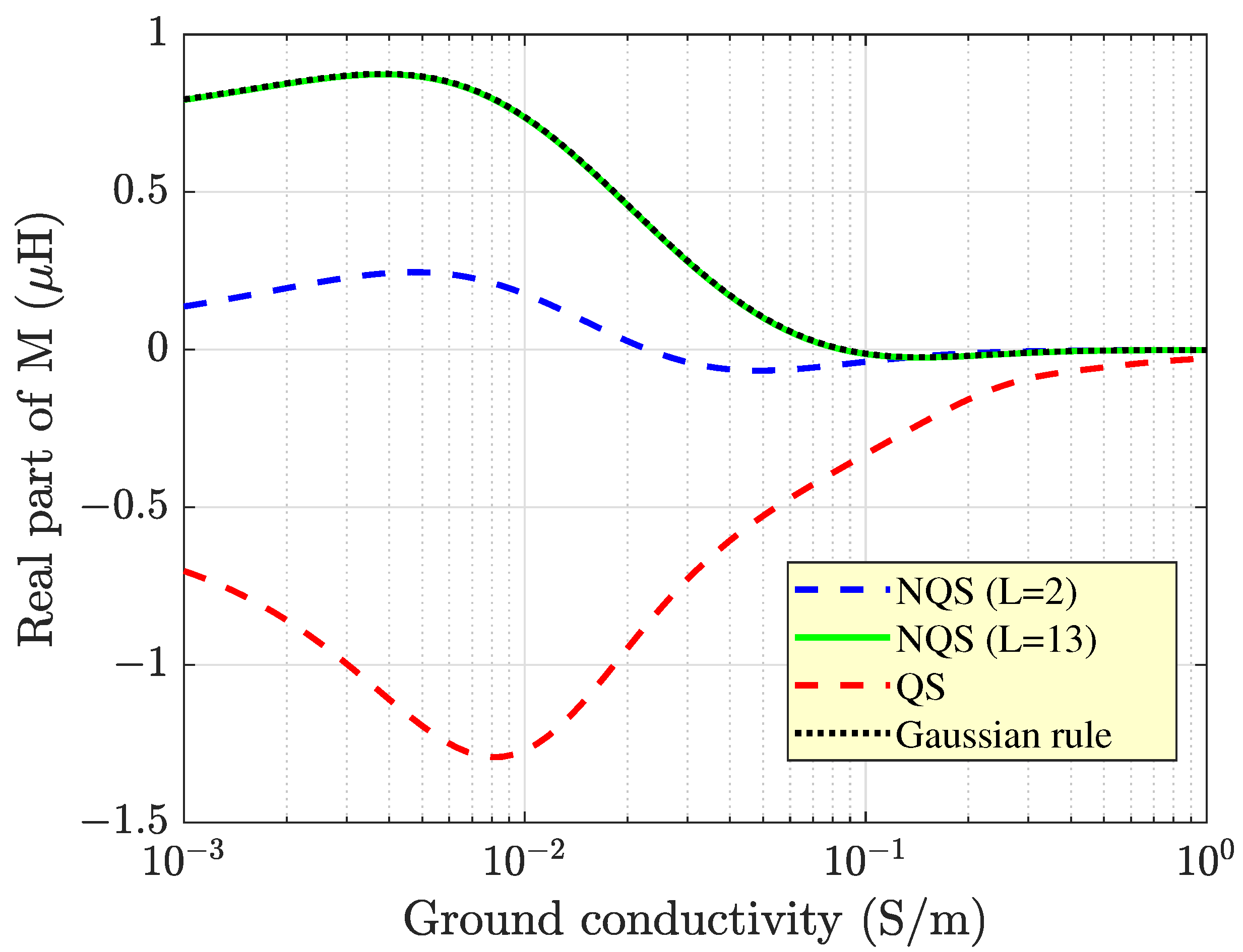
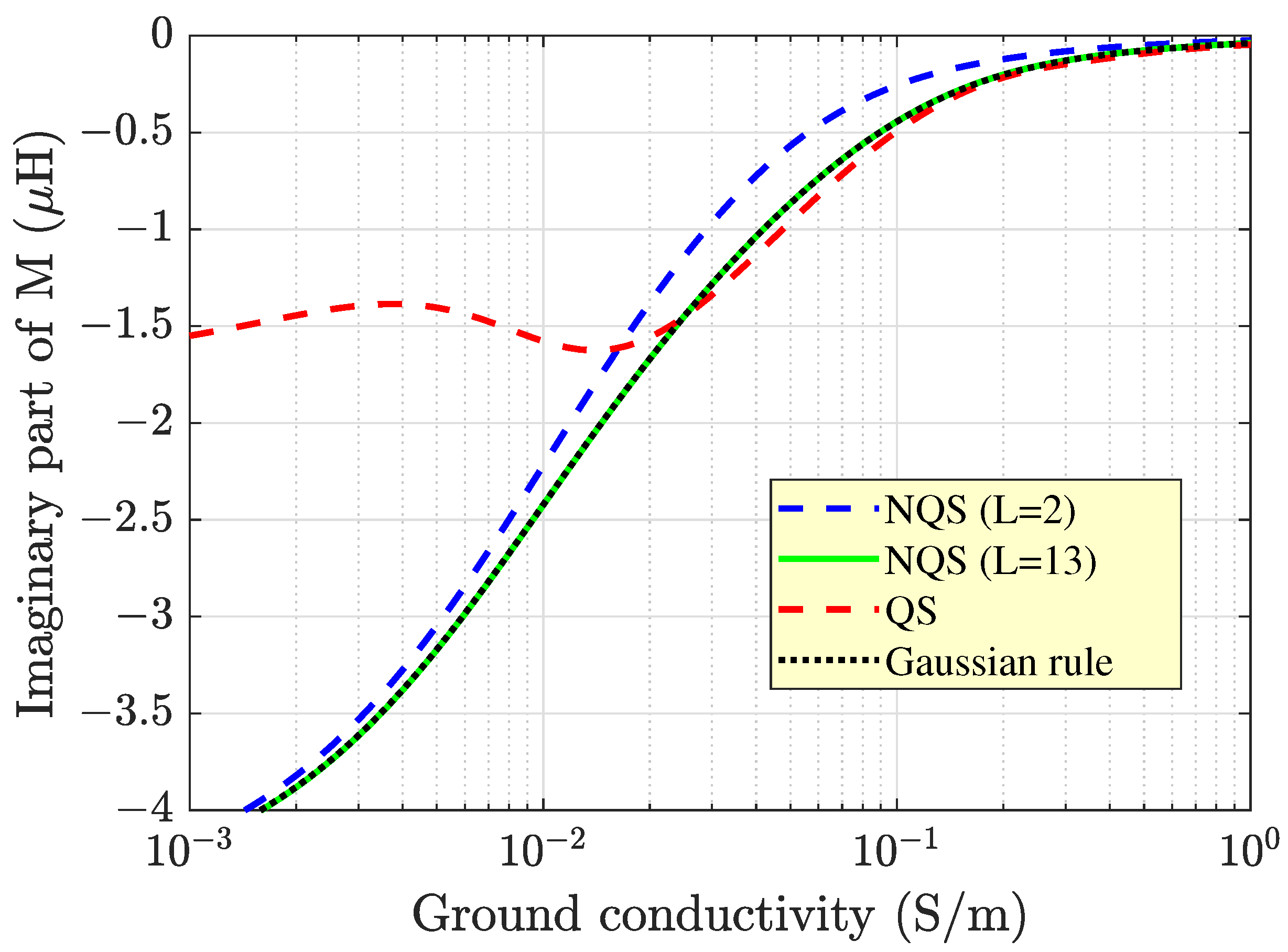
. The results of the calculations, depicted in
Figure 6 and
Figure 7, show that changing the conductivity did not affect the accuracy of Equation (
38) for
, which was comparable to that of the numerical integration of Equation (
18) everywhere. Conversely, the quasi-static approximation still failed because of the chosen operating frequency, which was well beyond the quasi-static frequency limit of
MHz.
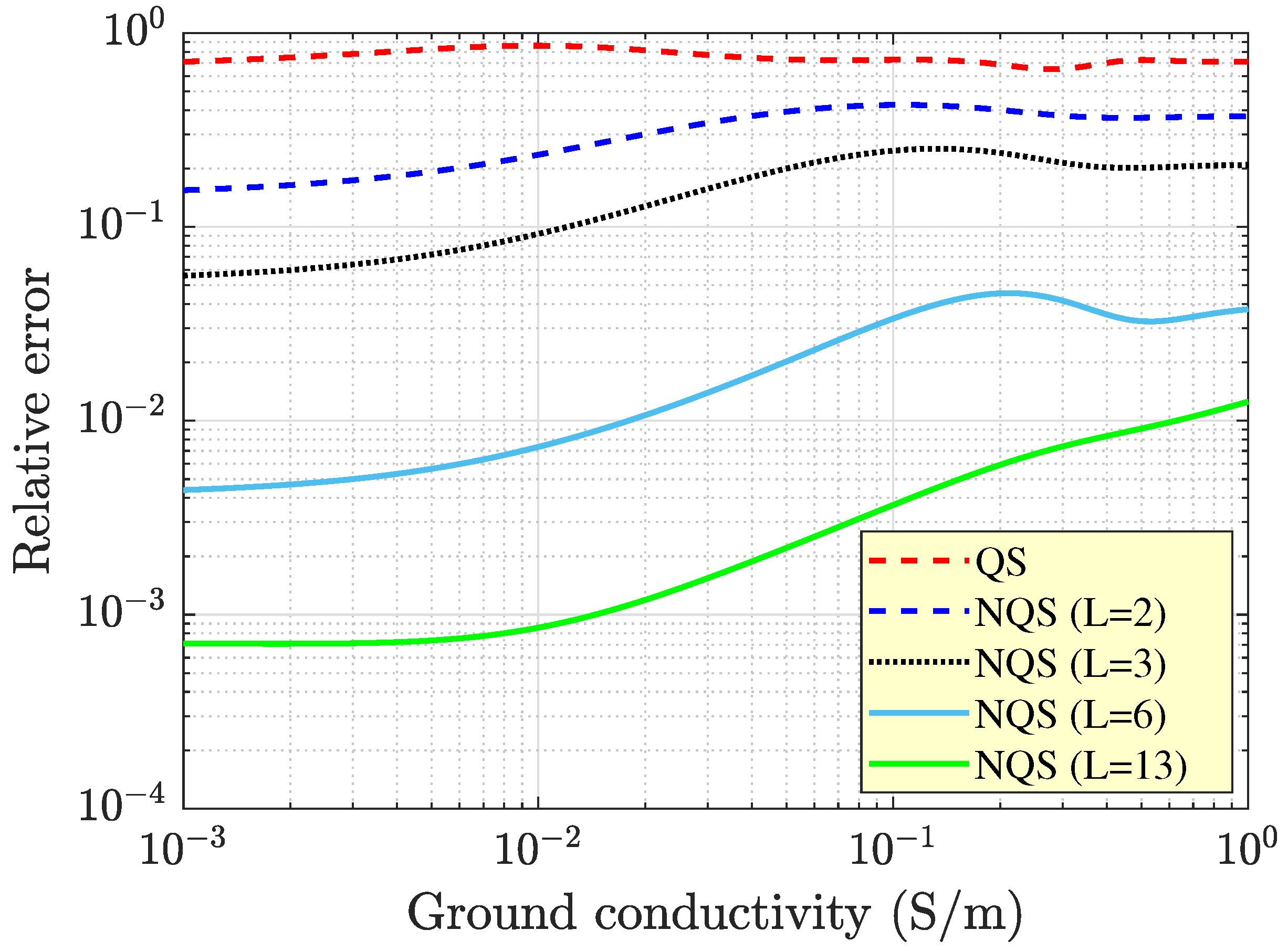
The enhanced level of accuracy offered by the proposed solution may be further appreciated with a glance at
Figure 8, which shows the
profiles of the relative errors of the outcomes from Equation (
38) and the quasi-static solution compared with the data from the Gaussian quadrature rule. The plotted curves show how Equation (
38) outperformed the previous solution regardless of the value of
, even when the sum was truncated at
. In addition, increasing
L always ensured enhanced precision of the results of the computation. However,
Figure 8 also indicates that the convergence of Equation (
38) was, in general, faster for lower values of
. For instance, when
mS/m, 6 terms of the infinite sum were to be retained in order to keep the error below the threshold of 1%, while at least 13 terms were required to achieve the same degree of accuracy when
S/m.
The profiles of
M against
also permitted acquiring useful information on the physics of the problem. For instance, the analysis of the curves of
Figure 6 revealed that after a slight increase, the real part of the mutual inductance decreased as the ground conductivity
increased. This happened because the ground approached the behavior of a good conductor. As a consequence, the electric field tangential to the top surface of the medium diminished in magnitude and so did the vertical magnetic field strength. The final result is that the magnetic flux linked with the secondary coil dropped.
On the other hand, a comparison between
Figure 4 and
Figure 7 tells us that changing the ground conductivity and changing the operating frequency generated opposite effects on the imaginary part of
M. In fact, while still negative in sign, the imaginary part then diminished in absolute value as
increased. This means that the power loss in the ground dropped, which can still be attributed to the fact that the behavior of the ground approached that of a good conductor. The subsequent reduction of the electric field strength
E, enhanced by the concomitant reduction of the skin depth, made the power loss density
decrease everywhere in spite of the increase in
.
Additional information on the impact of the electromagnetic parameters on
M may be acquired from analysis of the curves plotted in
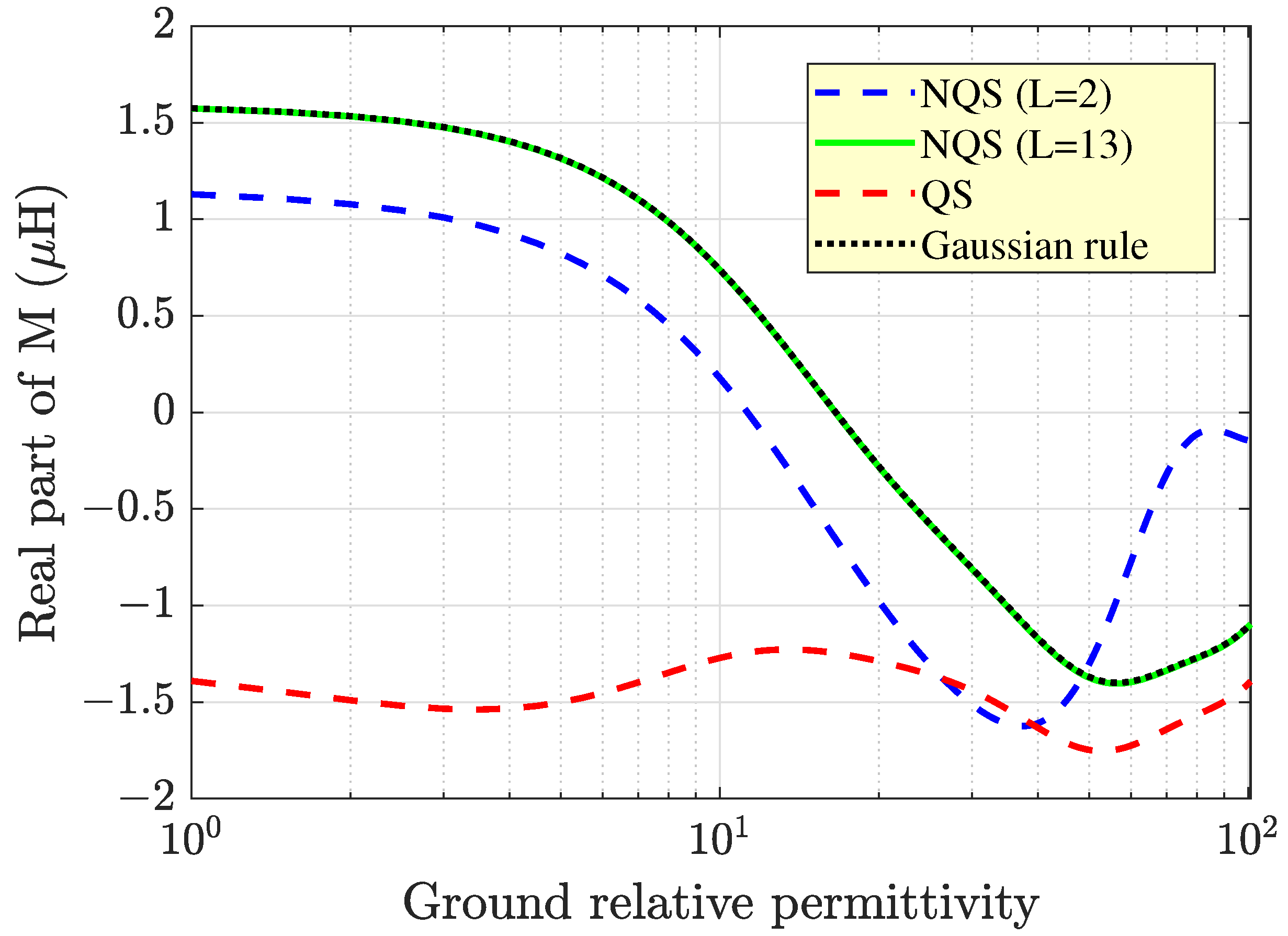
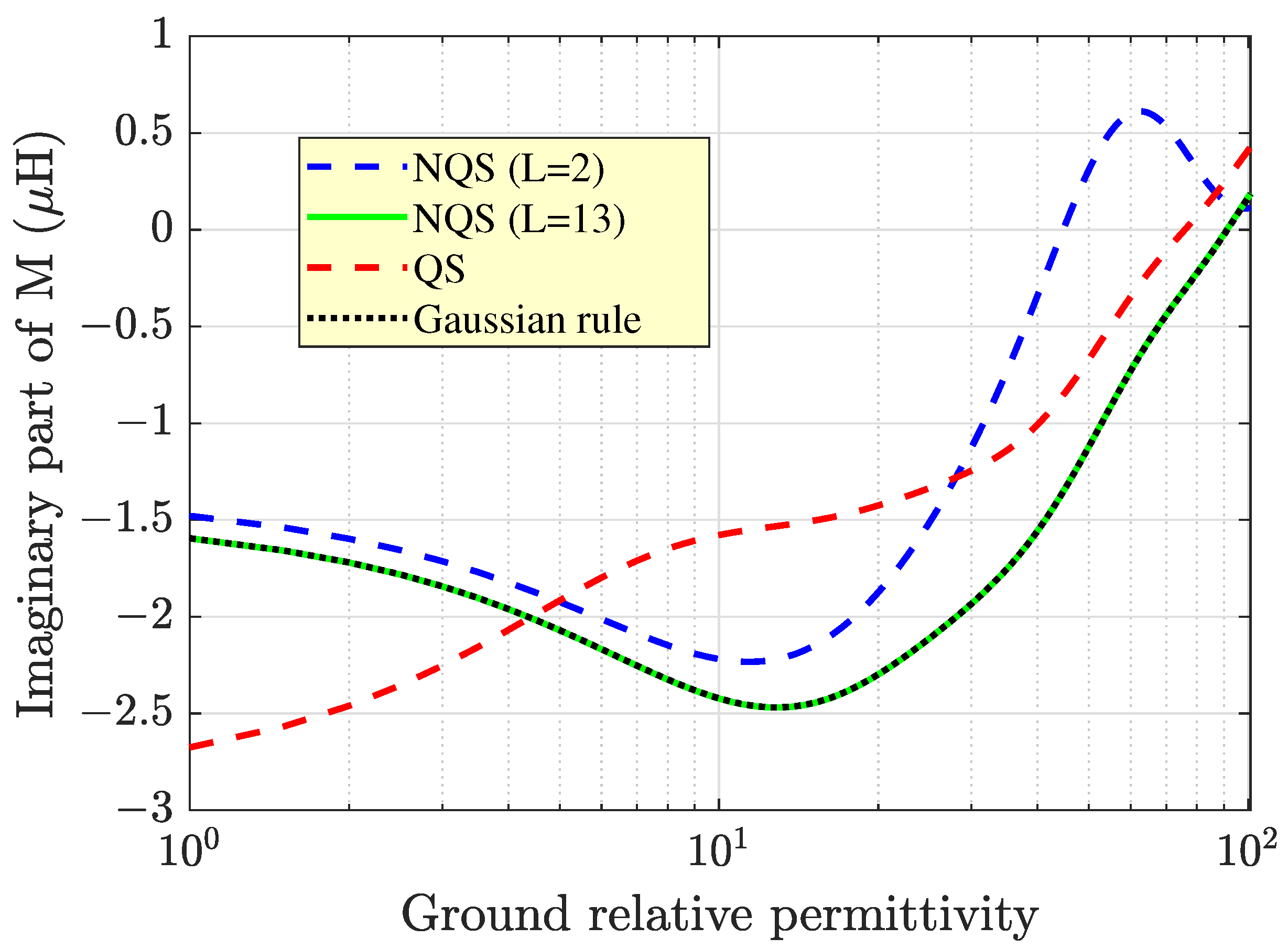
Figure 9 and
Figure 10, which depict profiles of the real and imaginary parts of
M against the ground relative dielectric permittivity
.
Here, the operating frequency and the electrical conductivity of the ground were assumed to be equal to 20 MHz and
10 mS/m, respectively, and the same coils as those in the preceding example were considered.
Figure 9 points out that the real part of
M exhibited a decreasing trend in most of the considered range of
. The explanation of this behavior is analogous to that underlying the plot of the inductance against the operating frequency, shown in
Figure 3. In fact, as
increased, the role of the displacement currents became more and more prominent, and this gave rise to propagation phenomena within the area surrounded by the receiving coil, with the consequence that the magnetic flux encompassed by the latter suffered from a significant reduction. Further increasing
made the real part of
M become negative in sign and then increase in absolute value. However, wavelength effects in the air space still prevented an unbounded increase in the (negative) magnetic flux, and the beginning of an oscillatory pattern was triggered in the
profile of the real part of
M.
On the other hand, from analysis of the curves in
Figure 10, it can be concluded that the absolute value of the imaginary part of
M increased with increasing
values as long as the latter was approximately smaller than 10. Thereinafter, the inductance diminished until it reached zero. This trend is explained as follows. For
, the quantity
was smaller than
, and the ground had the behavior of a good conductor. However, as
increased, the ground started to deviate from the good conductor behavior because of the enhanced importance of the displacement currents, and this reflected the increase in both the electric field strength inside the ground and the absolute value of the imaginary part of
M. For
, it yielded
mS/m, which is a value slightly greater than that of
. This is where the displacement currents started to predominate over the conduction currents. In principle, a further increase in
would make the ground become a poor conductor because of the enhancement of
. Instead, what happened was the opposite; since the ground approached a medium with a rather large permittivity, this condition made it close to a perfect electric conductor (PEC) [
50]. In fact, a high permittivity implies that the electric field inside the medium is coerced to fade away in order to keep the energy density bounded (as the latter was proportional to
, with
being the electric field vector). The consequence of this is that the electric field tangential to the air-ground interface must vanish on both sides of the interface itself, which occurred by virtue of the continuity of the tangential electric field across a plane boundary. In summary, as
, the PEC condition will have to be fulfilled on the top surface of the medium [
50]. This is the reason why when
was further increased starting from
, the absolute value of the imaginary part of the inductance (i.e., the fictitious resistance accounting for the Ohmic losses in the ground) was expected to decrease, in agreement with
Figure 10.
Finally, special attention should be paid to the choice of the appropriate dimension of the cross-section of the wires constituting the coils. In fact, in applications where the operating frequency is higher than 1 MHz, like those involving portions of the radio spectrum internationally reserved for industrial, scientific, and medical (ISM) purposes, the choice is affected by the skin effect in the conductor. It is well known that the skin effect causes the current density in a source coil to not flow evenly across the cross-section of the wire but rather concentrate near its surface. This would suggest keeping the wire radius (in the case of round wires) equal to or even smaller than the skin depth at the operating frequency so that no part of the wire is not utilized, and the wire is efficiently used. Not wasting precious space inside the wire theoretically leads to the best utilization of the cross-sectional area.
Yet, doing so in the present case would imply the usage of wires with extremely small diameters, which could not support the currents required by the coils of WPT systems (typically higher than 1 A). This happens because the heat build-up arising from a small cross-sectional area would trigger an unacceptable temperature rise in the system. To have an idea of the maximum amount of current which can be carried by a single wire at a given frequency, it suffices to consider the case of a round copper wire (
S/m) working at
MHz. At this frequency, the skin depth is
mm. If the choice is made to maximize the utilization of the cross-sectional area, the wire radius, denoted by
, is to be set equal to the skin depth (
). The corresponding cross-sectional area is
. On the other hand, a good guideline for the current density in the coils of wire is 400 circular mils per ampere (cmils/A), corresponding to
square mils per ampere and approximately equal to 0.2
/A [
51]. Hence, it was found that the current carrying capacity of the considered wire was only about 68 mA at 400 cmils/A (that is, 0.0137/0.2). This means that, for instance, the current of 1 A through the chosen cross-sectional area could not meet the guideline of 400 cmil/A. Hence, the desired current could not be handled by the single conductor. One way to pass more current than a conductor can handle is to use a multi-strand wire composed of several parallel strands of round wire. However, this might not always be the preferred solution as, depending on the current intensity, a number of twisted strands may be required, which may give rise to a bulky bunch which is hard to wind.
An alternative method to carry the prescribed current without exceeding the limitations imposed by guidelines is to still use a single round wire but choose an value much greater than that of . This represents the situation opposite to that considered at the beginning. The current will flow uniformly only near the surface of the conductor in an annular region with a thickness , while it will be nearly zero in the remaining large part of the cross-section. Thus, at sufficiently high frequencies, the skin effect significantly reduces the effective cross-sectional area carrying the current.
The main drawback of this solution is the increase in the conductor’s effective resistance, which is compensated by the possibility of increasing the wire radius until the desired current-carrying capacity is reached. For instance, consider the case where 1 A of current is to be carried by a copper wire at a frequency of 1 MHz. The cross-sectional area required to meet the guideline of 400 cmil/A is
= 0.2
. Since, at 1 MHz, the skin depth in a copper wire is
mm, and the effective cross-sectional area of the current flow may be expressed as
, it turns out that the radius of the conductor must obey the equality
mm. Hence, a wire radius of at least 0.5 mm can meet the prescribed requirements. At frequencies higher than 1 MHz, the skin depth further reduces, and larger radii are required to keep the effective cross-sectional area constant. In general, the radius of a conductor which can carry a given current
I at the operating frequency
f is given by
where
is to be determined from the knowledge of the admissible current density
J and the desired value of
I, related by the basic equation
. Thus, as the frequency
f increases,
is kept constant by adjusting
according to Equation (
53). This also permits keeping the power loss constant because of the maintenance of the effective resistance of the conductor. As is well known, the latter is referred to as the alternating current (AC) resistance, to be distinguished from the direct current (DC) resistance, which does not account for the current crowding near the conductor’s surface. In particular, at high frequencies, the per unit length AC resistance can be approximated by the expression [
52]
As a consequence, given the dimension and conductivity of the conductor, it worsens with the operating frequency as per .
