Abstract
To enhance equalization efficiency and address the issue of traditional equalization methods overlooking temperature factors, this paper proposes a multilayer equalization circuit for both intra-group and inter-group balancing. The traditional Buck-Boost equalization topology between groups is improved by incorporating a two-way interleaved inductor structure, which helps reduce equalization idle time. An adaptive fuzzy control equalization strategy for multiple objectives is applied to the topology. The state of charge (SOC) and temperature of the battery are used as key variables for equalization, with the equalization current dynamically adjusted based on changes in the SOC and temperature. This approach improves the balance between equalization speed and temperature control, reducing equalization time while limiting battery temperature rise. A simulation model is developed using MATLAB/Simulink. The simulation results demonstrate that, compared to the traditional Buck-Boost equalization topology, the proposed topology reduces equalization time by 15.1%. Additionally, under three different operating conditions, the equalization cotnrol strategy designed in this paper improves time efficiency by over 14% compared to traditional methods, while also reducing both the maximum temperature and temperature difference.
1. Introduction
Lithium-ion batteries are the primary energy source in storage systems due to their long cycle life, excellent discharge performance, and high energy density [1,2]. To meet high power demands, energy storage systems require high voltages, leading to the connection of hundreds or even thousands of lithium-ion batteries in series and parallel to form a battery pack [3]. Due to the differences in production processes that lead to differences in battery capacity and self-discharge rates during use, inconsistency between batteries occurs and becomes worse with the increase in batteries’ usage time. In order to reduce the inconsistency of battery packs, battery equalization is introduced [4,5]. Temperature impacts nearly all aspects of battery performance. High temperatures can accelerate battery aging, worsen inconsistencies, hinder the equalization process, and even lead to safety issues [6]. The temperature factor is often ignored in traditional equalization, which adversely affects battery equalization and lifetime. To enhance both equalization efficiency and battery lifespan, it is necessary to carry out research on equalization based on battery SOC and temperature. Battery equalization is mainly composed of topology and equalization strategy [7].
Equalization topologies are classified into two forms, passive and active equalization, depending on the method of energy transfer [8]. Passive equalization consumes excess energy in the form of heat by using energy-consuming elements connected in parallel at both ends of the battery. The passive equalization circuit topology is simple, with low equalization cost and high reliability, but the efficiency is not impressive, and the large amount of thermal energy generated also negatively affects the battery thermal management [9,10]. In contrast to passive equalization, active equalization uses an energy storage element as the energy transfer element, which transfers energy to the low-energy battery through capacitors, inductors, and transformers, avoiding thermal problems, and also effectively improving equalization speed and energy utilization [11,12].
Reference [13] presents a single inductance balancing circuit utilizing Buck-Boost, which enables balancing between adjacent cells via inductance. When two batteries are far apart, only the middle battery can be used as an energy transfer, resulting in low balancing efficiency. Each energy transfer will cause idle balancing and reduce balancing speed. Reference [14] shows a balanced circuit with any number of inductors. This circuit achieves energy transfer between any battery cell, but the increase in the number and volume of balancing circuits is not conducive to balancing multiple battery cells. Reference [15] shows a cuk equalization circuit, which achieves the energy transfer between arbitrary batteries, but the use of active devices is high, which increases the cost of the circuit. In order to solve the above topology problems, this paper designs a multi-layer equalization circuit to achieve equalization within and between groups. Energy transfer between any battery within the group can be achieved, and the Buck-Boost balancing circuit between groups has been improved to reduce idle time in the balancing cycle and improve balancing efficiency.
Equalization variables are selected first, and then equalization strategies are decided after. Equalization variables are mainly voltage and SOC [16]. Voltage as an external parameter of the battery is easy to measure, while as an external characteristic of the battery, it cannot fully respond to the capacity and internal resistance. SOC, as a comprehensive performance of the battery, can better improve the inconsistency of the battery [17]. However, in the process of battery equalization, the temperature of the battery is also a non-negligible point, which is related to the performance of equalization and the safety of the battery. In this paper, SOC is selected for balancing, and temperature is used as the constraint to limit the rise in battery temperature while improving the battery inconsistency. Traditional equalization control algorithms are mainly divided into maximum–minimum method, mean–difference method, etc. The control is relatively simple, but the equalization target is considered single, and it is also easy to over-equilibrate, resulting in low equalization efficiency. Reference [18] shows a strategy that considers SOC and temperature balance, using a model predictive control to balance current and limit battery temperature rise. However, an accurate model needs to be established, and the modeling work is very complex when multiple batteries are used. Reference [19] shows a nonlinear optimal control problem with equalization and imbalance constraints based on battery SOC and temperature. And sequential quadratic programming (SQP) is used for solving, ultimately achieving equalization between temperature and SOC. However, the large computational complexity of the SQP algorithm results in slow equalization speed. In this paper, a fuzzy control strategy that does not require an accurate mathematical model is used, which has strong nonlinearity and robustness. By using fuzzy control as the balancing strategy, the balancing efficiency has been improved, without considering the changes in battery temperature during balancing [20,21,22,23]. To address the coordination challenge between equalization and temperature, this paper introduces a SOC and temperature-based adaptive fuzzy control strategy.
The main contributions of this paper are as follows.
- (1)
- This article proposes a multi-layer balanced topology structure for intra-group and inter-group balancing.
- (2)
- The balanced topology structure within the group can achieve energy transfer between any battery. Reduce energy loss caused by the need to separate batteries as energy transfer when they are far apart.
- (3)
- Inter-group balanced topology structure improves the traditional Buck-Boost topology structure by adopting a dual interleaved inductor structure to reduce balancing idle time.
- (4)
- This paper presents a SOC and temperature-based adaptive fuzzy control strategy that uses SOC as the balancing target and temperature as a limiting factor. It adjusts the balancing current dynamically to enhance the balancing speed while preventing excessive battery temperature rise.
The structure of the paper is as follows: The second section outlines the intra-group and inter-group equalization topologies and their principles. The third section details the design of the adaptive fuzzy control strategy, considering both SOC and temperature. The fourth section verifies the equalization topology and adaptive fuzzy control strategy through MATLAB/Simulink modeling and simulations. Finally, the fifth section presents the conclusions.
2. Equalization Circuit Analysis
The multilayer equalization circuit topology designed in this paper is demonstrated using 16 batteries, as illustrated in Figure 1. Every four batteries form a group, and each group is equipped with an intra-group equalizer. Each group of batteries is equipped with an inter-group equalizer. The first layer of equalization refers to the internal equalization of the battery group. The second layer of equalization refers to the equalization between individual battery packs. The third level of equalization refers to equalization between two battery packs. When equalizing, intra-group equalization is carried out first, and inter-group equalization is carried out after intra-group equalization is completed, so that equalization is carried out in an orderly manner and the equalization efficiency is accelerated.
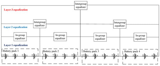
Figure 1.
Overall equalization topology.
2.1. In-Group Equalization Circuits
This paper adopts a topology based on inductance as the energy transfer between batteries, and analyzes it as an example of a topology with four battery cells in series; the topology is shown in Figure 2. B1–B4 are the four battery cells. D1–D8 are diodes, and M1–M8 are MOSFET thyristors, and the path of equalization can be altered through the on–off coordination of diodes and thyristors to realize the selection of equalization cells. L is an inductor which acts as an intermediary for energy transfer.
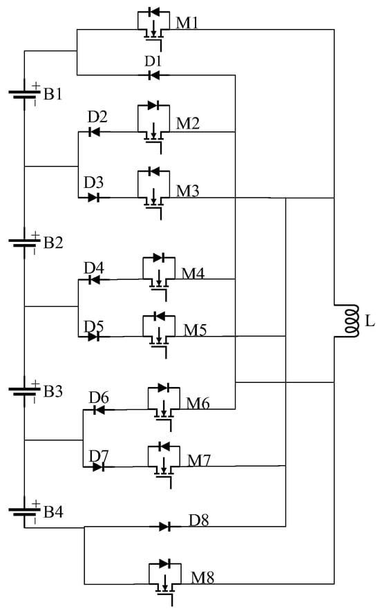
Figure 2.
In-group equalization topology.
Take B2 and B4 equalization as an example. Assuming the SOC of battery B2 is higher than that of B4, the equalization process consists of two stages: discharging from B2 and charging of B4. The details of the charging and discharging processes are outlined below.
- (1)
- B2 discharge (t ∈ [0~DT)): at t = 0, all the thyristors are in the off state, the current on the inductor is initially 0. The gates of thyristors M3 and M4 receive the command to conduct, while others remain closed. Current can flow through diodes D3 and D4. Battery B2 supplies power to the inductor, causing the current through the inductor L to increase gradually, converting electrical energy into magnetic energy stored in the inductor, and the current forms a loop along B2, D3, M3, L, M4, D4, and B2, as shown by the red line in Figure 3a. The discharge current of B2 and the inductor current are shown in Equations (1) and (2).is the discharge current of B2, represents the peak current of the inductor, is the voltage of B2, T represents the total equalization period, while D is the duty cycle, which controls the current flowing through the inductor.
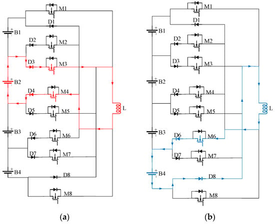 Figure 3. Charge–discharge current diagram: (a) B2 discharging and (b) B4 charging.
 - (2)
- B4 charging (t ∈ [DT~T]): when t = DT, M3 and M4 are off, M6 is on, L, M6, D6, B4, D8, and L constitute a loop, the inductor L releases the stored energy to convert the magnetic energy into electrical energy, and the current gradually decreases to 0, as shown by the blue line in Figure 3b. The charging current of B4 and the inductor current are shown in Equation (3).where is the charging current of B4, is the voltage of B4. As shown in Equations (1)–(3), the magnitude of is determined by the duty cycle D, both during charging and discharging.
2.2. Intergroup Equalization Circuit
The Buck-Boost equalization circuit needs to rely on the PWM control to complete the equalization, so there will be idle time in one cycle of a single inductor. During the equalization process, each battery will be idle due to the energy transfer between the inductor and another battery, resulting in a longer equalization time. To enhance the equalization speed, this paper uses a two-way interleaved equalization topology based on inductors to reduce the idle time in one cycle, and analyzes the intergroup equalization topology for the first layer of Battery Packs 1 and 2, as shown in Figure 4. This topology comprises two inductors (La and Lb), four thyristors (Ma1, Ma2, Mb1, and Mb2), and two battery packs (BP1 and BP2).
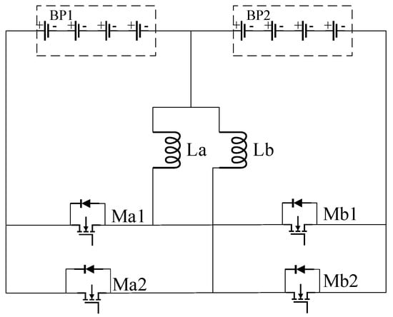
Figure 4.
Intergroup equalization topology.
Equalization principal analysis: If the SOC of battery pack 1 exceeds that of battery pack 2 and the startup threshold, equalization is activated.
- (1)
- BP1 discharges, (t ∈ [0~DT)) switching tube Ma1 conducts, Ma2, Mb1, and Mb2 remain off, battery pack 1 charges inductor La, the current on the inductor gradually increases, the current is shown in Figure 5a, the current of the inductor is shown in Equations (4)–(5).
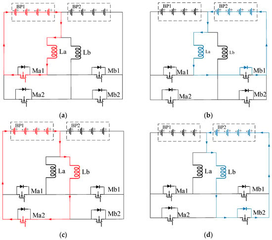 Figure 5. Charge/discharge current diagrams: (a,c) BP1 discharging (b,d) BP2 charging.
 - (2)
- BP2 charges, (t ∈ [DT~0.5T)) switching tube Ma1 turns off, releasing the energy in inductor La, the diode on Mb1 conducts, the current on the inductor decreases gradually, and the current is as shown in Figure 5b, and the current in inductor La drops to 0, signaling the end of charging. The current in inductor La is shown in Equation (6).
- (3)
- BP1 discharges, (t ∈ [0.5T~(0.5 + D)T)) switching tube Ma2 conducts, Ma1, Mb1, and Mb2 remain off, and battery pack 1 charges inductor Lb with the current shown in Figure 5c.
- (4)
- BP2 charges, (t ∈ [(0.5 + D)T~T]) switching tube Ma2 turns off, releasing the energy in inductor Lb, the diode on Mb2 conducts, and the current is shown in Figure 5d.
The comparison of inductor current waveforms in a single cycle between the Buck-Boost equalization topology and inductor-based two-way interleaved equalization topology is shown in Figure 6. The inductor currents of Buck-Boost topology are shown in Figure 6a, which can only complete the equalization once in a cycle, resulting in more idle time. The inductor current of the inductor-based two-way interleaved topology is shown in Figure 6b, and iLa and iLb are the currents on the two inductors as the red and blue lines in the figure, respectively, which can complete the equalization twice in one cycle, reducing the equalization idle time and improving the equalization efficiency.

Figure 6.
(a) Buck-Boost topology inductor current; (b) dual interleaved topology inductor current.
3. Battery Equalization Control Strategy
3.1. Selection and Analysis of Equalization Variables
To achieve rapid and efficient equalization, a larger equalization current is typically used to address battery inconsistency. However, this generates energy loss due to the battery’s internal resistance, causing a rapid increase in temperature. The battery’s temperature influences nearly all of its parameters, which, in turn, limits the performance of the equalization process. Additionally, the battery’s optimal operating temperature ranges from 15 °C to 35 °C; if the battery continues to be used at high temperatures, its capacity will be compromised. At the same time, high temperatures are prone to the lithium-ion precipitation phenomenon, and in serious cases, the short circuit between the positive and negative electrodes can trigger thermal runaway. To better address the issue of balancing battery inconsistency and temperature. This paper proposes a multi-objective adaptive fuzzy control equalization strategy for intra-group equalization, based on battery SOC and temperature. It selects different equalization currents according to the battery’s temperature states, improving the coordination between battery inconsistency and temperature to some extent. For inter-group equalization, it is difficult to accurately model multiple battery variables using the fuzzy control, so the mean difference algorithm is used for equalization.
The battery’s SOC can be represented by Equation (7), where is the remaining charge and is the rated charge. The core temperature of battery during charging and discharging at any given moment is given by Equation (8) [24,25]. Where is the thermal resistance, is the thermal time constant, is the ambient temperature, is the total heat generated during charging or discharging, which can be expressed as Equation (9), where T is the internal temperature of the battery, E is the open circuit voltage, is the rated voltage at T temperature, is the actual voltage at T temperature, is the reversible voltage temperature coefficient, is the battery current. From Equations (8) and (9), the battery temperature rise can be limited by changing the amount of current in the equalization process.
3.2. Equalization Control Strategy Based on Adaptive Fuzzy Control
This paper proposes a multi-objective coordinated control equalization strategy based on SOC and temperature, analyzing the coordination issue between battery inconsistency and temperature through equalization circuit topology and battery principles. Given that the equalization system is a complex, time-varying model, establishing an accurate mathematical model is challenging, making conventional control theories and algorithms inadequate for solving the equalization problem. The fuzzy control, which does not rely on an exact mathematical model, is well-suited for nonlinear systems like battery equalization. Figure 7 illustrates the schematic of the fuzzy controller, consisting of four main components: fuzzification, rule establishment, fuzzy inference, and defuzzification. Fuzzy control converts precise inputs into fuzzy variables, processes them through fuzzy reasoning based on a knowledge base of practical experience, and then transforms the results into precise outputs via defuzzification.
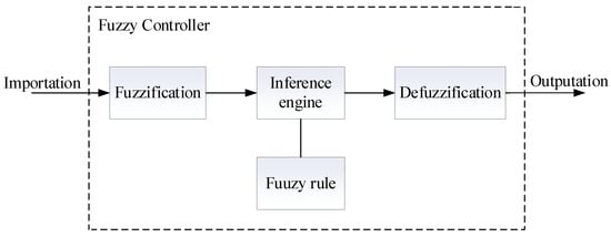
Figure 7.
Fuzzy controller structure.
To address the coordination issue between battery inconsistency and temperature, this paper designs separate fuzzy controllers for SOC and temperature. An adaptive fuzzy controller is then introduced to combine the outputs of both controllers through a weighted approach. This method takes into account the duty cycles related to both inconsistency and temperature, enabling real-time adjustment of PWM waveforms and the adjustment of balanced current. The equalization process is shown in Figure 8.
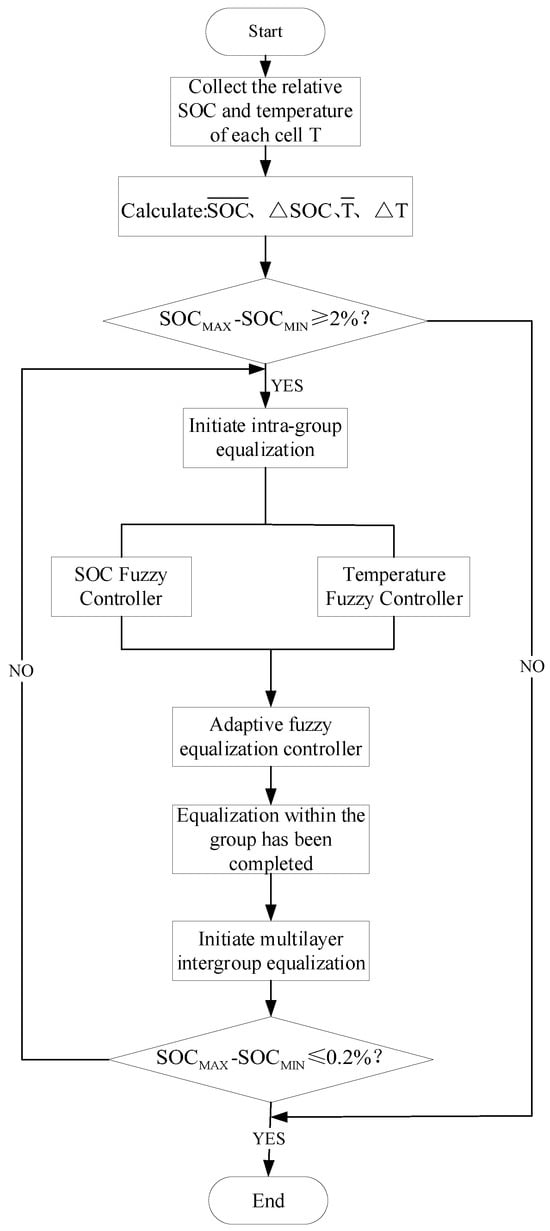
Figure 8.
Equalization flow chart.
3.2.1. SOC and Temperature Fuzzy Controller Design
The input variables effectively represent the consistency of the battery pack and the temperature distribution.
The SOC fuzzy controller proposed in this paper has two input variables and one output variable. They are , , and one output variable DCsoc. is the extreme difference in battery SOC, is the average value of battery SOC, and DCsoc is the duty cycle considering SOC equalization. The two input variables are defined as follows.
In Equations (10) and (11), is the maximum value of the SOC of the nth battery, and is the minimum value of the SOC of the nth battery. represents the SOC of the nth battery, while denotes the average SOC value of the battery pack.
The temperature fuzzy controller designed includes two input variables, labeled as and , and one output variable, DCt. represents the average battery temperature, is the difference between the maximum and average battery temperatures, and DCt is the duty cycle for temperature equalization. The definitions of the two input variables are as follows.
In Equations (12) and (13), represents the maximum temperature of n batteries, and represents the average temperature of n batteries. is the temperature of the nth battery.
The ranges of and are set to (0%, 50%) and (0, 100%), the ranges of and are set to (0, 10) and (20, 40), and the ranges of DCsoc and DCt are set to (0, 0.6). Each fuzzy subset is divided into five: vs. (very small), S (small), M (medium), L (large), and VL (very large). Figure 9 shows the membership function diagram of the fuzzy controller.
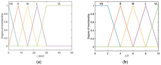
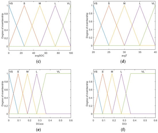
Figure 9.
(a,c,e) and (b,d,f) show the affiliation functions of the SOC and temperature fuzzy controllers, respectively.
The fuzzy control rules for SOC and temperature are as follows. Regarding the SOC fuzzy controller rules: when is large or small, for the purpose of protecting the battery, a smaller output duty cycle is used to generate a smaller equalization current to avoid excessive charging and discharging of the battery. When is larger, the duty cycle is appropriately increased to speed up the equalization rate. When is moderate, a larger output duty cycle is used to produce a larger equalization current to quickly improve the inconsistency of the battery.
Rules about the temperature fuzzy controller: when is small, the battery temperature is generally low; use a larger output duty cycle to generate a larger equalization current and reduce the equalization time. When is large, the battery temperature difference is large; thus, a smaller output duty cycle is used to limit the rise in battery temperature. The SOC and T fuzzy control rules are tabulated as shown in Table 1 and Table 2.

Table 1.
SOC fuzzy control rules.

Table 2.
T fuzzy control rules.
The defuzzification method used in the SOC fuzzy controller and T fuzzy controller is the re-centering method, as shown in Equation (14). is the output value, and is the output of the fuzzy reasoning, which represents the membership function of the variable z. The corresponding three-dimensional coordinate plot of the input and output is shown in Figure 10.
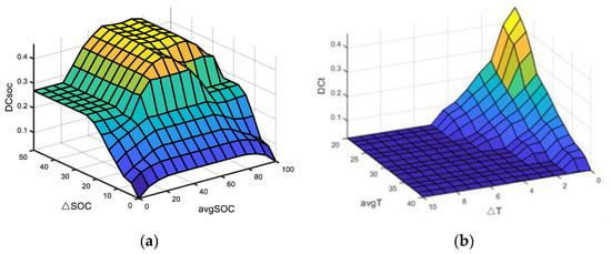
Figure 10.
Three-dimensional coordinate diagram of the fuzzy control: (a) SOC fuzzy control; (b) T fuzzy control.
3.2.2. Adaptive Fuzzy Controller Design
The input is the average temperature of the battery pack , while the outputs are the weight coefficients and , representing the weights of the SOC fuzzy controller and the temperature fuzzy controller, respectively. After the adaptive fuzzy controller assigns the weights, the resulting desired duty cycle DC is given by Equation (15).
where and represent the duty cycles of the SOC and temperature fuzzy controller outputs, respectively. and are the weighting coefficients of the adaptive fuzzy control outputs, each less than one.
By recombining and through the and weighting coefficients, coordinated SOC and temperature equalization is considered at any moment during the equalization process, and SOC equalization or T-equalization is chosen to dominate according to the average temperature of the battery pack in the current state. The battery pack is set to (20, 40), and the range of the weighting coefficients and is set to (0, 1). The input–output affiliation diagram is shown in Figure 11.
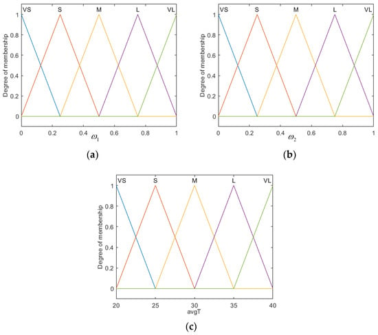
Figure 11.
(a,b) show the plot of the affiliation function for and , respectively; (c) shows the plot of the affiliation function for mean temperature.
The rules of the adaptive fuzzy controller are as follows: when the average temperature is between 20 °C and 30 °C, SOC equalization is prioritized, while the T-equalization weight gradually increases with the rising temperature. This allows for larger equalization currents and faster equalization within the acceptable temperature range. When the average temperature is between 30 °C and 40 °C, T-equalization becomes the dominant factor, and the SOC equalization weight decreases with the increasing temperature. In this range, the equalization current is kept small to limit the battery’s temperature rise. The fuzzy control rules are outlined in Table 3. The defuzzification method used in the adaptive fuzzy control is the center of gravity method, and the two-dimensional coordinate diagram for its input and output is shown in Figure 12.

Table 3.
Adaptive fuzzy control rules.
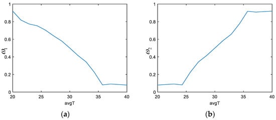
Figure 12.
(a,b) 2D coordinate plots of and versus mean temperature, respectively.
4. Equalization System Construction and Simulation
In order to test and verify the performance of the topology and equalization algorithm proposed in this paper. A simulation model for the balancing system is developed in MATLAB/Simulink based on the proposed circuit structure and balancing strategy. Taking 16 batteries as an example, the serial numbers of the 16 batteries are B1–B16. They are grouped in the order of battery serial numbers, with four batteries in each group and a battery parameter of 3.6 V/48 Ah. The SOCs of the 16 batteries are set to 40%, 64%, 67%, 45%, 52%, 53%, 60%, 42%, 48%, 54%, 51%, 46%, 56%, 41%, 43%, and 65%. The temperature of the battery is set to 25 °C, and there is no heat exchange with the outside world.
The equalization inductance between groups is set to 1 H, the equalization inductance within groups is set to 0.001 H, and the MOS tube and diode are the default parameters set by Simulink. Equalization starts when the condition of equalization on is . The equalization stop condition is , and the equalization ends. The evaluation metrics include equalization time, maximum temperature, and maximum temperature difference to assess the performance of improving battery inconsistency. The simulation model consists of a battery module, a single inductor equalization module within a group, an inter-group equalization module, a switch control module, and a fuzzy control duty cycle module. According to the SOC and temperature state of the battery, the switching module selects the on and off time.
4.1. Topology Performance and Adaptive Fuzzy Control Algorithm Validation
4.1.1. Stationary Simulation
In order to verify the improvement of the multilayer intergroup topology with the performance of the adaptive fuzzy control equalization strategy in this paper, compared with the intergroup as Buck-Boost topology using the mean-difference (MD) equalization, and the adaptive fuzzy control (AFC) equalization strategy is introduced on the intergroup two-way interleaved topology. The three SOC and temperature variations are shown in Figure 13, and the specific temperature data are shown in Table 4.
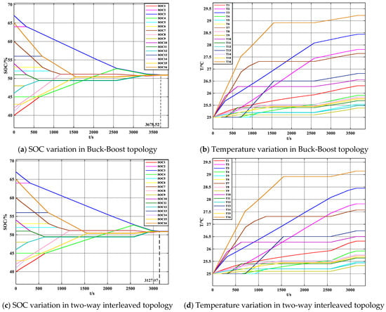
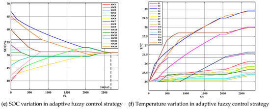
Figure 13.
(a,c,e) and (b,d,f) are the changes in SOC and temperature in the three equalization processes, respectively.

Table 4.
Comparison of static equalization temperatures.
The inter-group topology is Buck-Boost, and the changes in SOC and temperature during the equalization process are shown in Figure 13a,b. During group balancing, there is excessive idle time, leading to an unnecessarily long balancing duration. The process takes 3678.52 s to complete, resulting in a maximum temperature rise of 29.22 °C and a maximum temperature difference of 3.83 °C across the individual cells.
The intergroup topology is two-way interleaved, which reduces the idle time in the equalization cycle. It takes 3127.07 s to complete the equalization, saving 15.1% of the equalization time. The maximum temperature and the maximum temperature difference are also reduced. The changes in SOC and temperature during the equalization process are shown in Figure 13c,d.
AFC strategy is introduced on the two-way interleaved topology, with the changes in SOC and temperature shown in Figure 13e,f. Based on the variations in battery SOC and temperature, the duty cycle is adjusted to dynamically change the equalization current. The equalization is completed in just 2669.63 s, reducing the equalization time by 27.4% and 14.6% compared to the Buck-Boost topology and the interleaved topology, respectively. In terms of temperature, the maximum temperature decreases by 0.31 °C and 0.23 °C, and the maximum temperature difference decreases by 0.25 °C and 0.23 °C compared to the previous two topologies.
Figure 14a,b show the variation of and with the average temperature during the equalization process of the second battery group with the trend of the DC, DCsoc, and DCt. During the balancing process of the second group of batteries B5–B8, the DC will dynamically adjust with the inconsistency of the battery pack and temperature changes, shortening the balancing time while effectively limiting the temperature rise in the batteries.
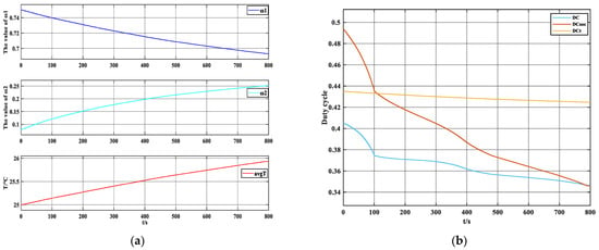
Figure 14.
(a) Trends of and with avgT; (b) trends of DC, DCsoc, and DCt.
4.1.2. Charging and Discharging Simulation
To effectively showcase the benefits of the adaptive fuzzy control equalization strategy (AFC) presented in this paper, charging and discharging equalization simulations are performed and compared with the MD method. The simulation is validated through constant current charging and discharging. The variations in charging and discharging SOC and temperature based on both adaptive fuzzy control equalization and mean-difference equalization are presented in Figure 15 and Figure 16. The specific temperature data is provided in Table 5.
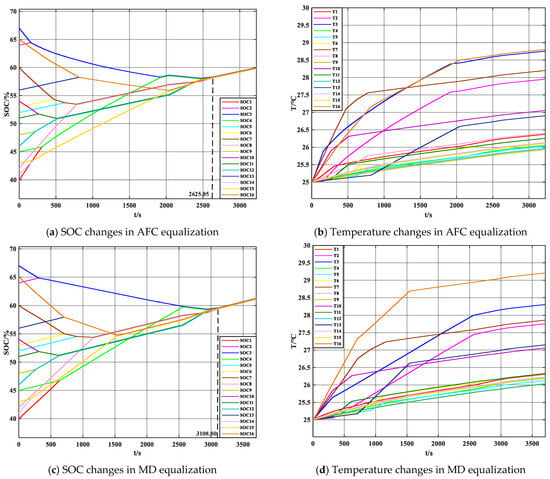
Figure 15.
SOC and temperature changes under two control strategies under charging.
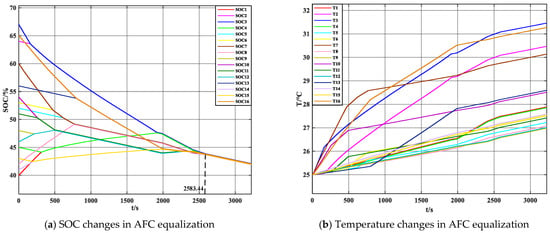
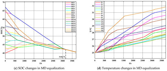
Figure 16.
SOC and temperature changes under two control strategies under discharge.

Table 5.
Charging/discharging equalization temperature simulation comparison.
In Figure 15a,c, the SOC changes during charging using the AFC and MD equalization algorithms are shown, with equalization times of 2625.05 s and 3108.80 s, respectively. In Figure 16a,c, the SOC changes during discharging with the AFC and MD equalization algorithms are presented, with equalization times of 2583.44 s and 3146.74 s, respectively. In both charging and discharging states, the equalization time using the AFC algorithm is reduced by 15.6% and 17.9%, respectively.
From a temperature perspective, during the charging equalization state, the temperature changes under AFC and MD equalization are shown in Figure 15b,d. The maximum temperature, average temperature, and maximum temperature difference are 28.68 °C and 29.09 °C, 26.70 °C and 26.71 °C, and 2.88 °C and 3.19 °C, respectively. In the discharging equalization state, the temperature changes under AFC and MD equalization are shown in Figure 16b,d. The maximum temperature, average temperature, and maximum temperature difference are 31.08 °C and 31.48 °C, 28.01 °C and 28.37 °C, and 4.5 °C and 4.54 °C, respectively. Compared to the MD method, the AFC results in a decrease of 0.41 °C and 0.4 °C in maximum temperature, a reduction of 0.01 °C and 0.36 °C in average temperature, and a decrease of 0.31 °C and 0.04 °C in maximum temperature difference.
Combined with simulation results in both the static and charging/discharging states, it can be verified that the adaptive fuzzy control equalization algorithm offers the advantage of dynamically adjusting the equalization current. This adjustment accelerates the equalization speed while limiting the rise in battery temperature and reducing the temperature difference between the batteries.
5. Conclusions
This paper presents a balancing strategy for energy storage lithium battery packs based on a multilayer topology. The proposed approach uses a centralized inductive topology within the battery pack to facilitate energy transfer between individual cells. Additionally, it enhances the traditional Buck-Boost balancing topology by incorporating a two-way interleaved design, which reduces idle time during the balancing cycle and speeds up the process. Compared to conventional Buck-Boost equalization methods, the new topology significantly improves equalization speed while minimizing battery temperature rise. Furthermore, an adaptive fuzzy control algorithm, which takes both State of Charge (SOC) and temperature into account, is introduced to dynamically adjust the equalization current, addressing the challenge of balancing speed and temperature coordination. Simulations validate the performance of the proposed topology and algorithm, showing a 15.1% reduction in equalization time, more than a 14% improvement in time efficiency, and a decrease in both maximum temperature and temperature difference.
Author Contributions
Writing, Validation and Formal analysis, X.S. and G.Z.; Software and Resources, Funding acquisition, G.Z.; Writing—Review and Editing, S.A., H.Z. and X.W. All authors have read and agreed to the published version of the manuscript.
Funding
This work was supported in part by the National Natural Science Foundation of China (No. 52377017, 52077203).
Data Availability Statement
Data will be made available on request.
Conflicts of Interest
H.Z. and X.W. are employed by State Grid Taizhou Power Supply Company. The Company had no role in the design of the study; in the collection, analyses, or interpretation of data; in the writing of the manuscript, and in the decision to publish the results. Others declare no conflicts of interest.
References
- Qi, X.B.; Fang, M.Z.; Wang, Y.; Wang, Y.B.; Chen, Z. An Equalization Current Ripple Cancellation (ECRC) Converter-Based Centralized Equalization System for Series-Connected Battery Strings. IEEE Trans. Transp. Electrif. 2023, 9, 2765–2777. [Google Scholar] [CrossRef]
- Luo, S.Y.; Qin, D.C.; Wu, H.X.; Wang, T.T.; Chen, J.Y. Multi-Cell-to-Multi-Cell Battery Equalization in Series Battery Packs Based on Variable Duty Cycle. Energies 2022, 15, 3263. [Google Scholar] [CrossRef]
- Doan, N.Q.; Shahid, S.M.; Choi, S.J.; Kwon, S. Deep Reinforcement Learning-Based Battery Management Algorithm for Retired Electric Vehicle Batteries with a Heterogeneous State of Health in BESSs. Energies 2024, 17, 79. [Google Scholar] [CrossRef]
- Guran, I.C.; Florescu, A.; Perisoara, L.A. SPICE Model of a Passive Battery Management System. IEEE Access 2024, 12, 4000–4014. [Google Scholar] [CrossRef]
- Tang, R.L.; Wang, H.J.; Lin, Q.; Lai, J.G.; Zhang, Y. Double-layer state of health equalization based on cooperative coevolution for large-scale lithium battery system. J. Clean. Prod. 2024, 436, 140702. [Google Scholar] [CrossRef]
- Kim, J.; Oh, J.; Lee, H. Review on battery thermal management system for electric vehicles. Appl. Therm. Eng. 2019, 149, 192–212. [Google Scholar] [CrossRef]
- Feng, F.; Hu, X.S.; Liu, J.F.; Lin, X.K.; Liu, B. A review of equalization strategies for series battery packs: Variables, objectives, and algorithms. Renew. Sustain. Energy Rev. 2019, 116, 109464. [Google Scholar] [CrossRef]
- Kivrak, S.; Özer, T.; Öguz, Y.; Kelek, M.M. Novel active and passive balancing method-based battery management system design and implementation. J. Power Electron. 2021, 21, 1855–1865. [Google Scholar] [CrossRef]
- Hua, Y.; Zhou, S.D.; Cui, H.G.; Liu, X.H.; Zhang, C.; Xu, X.W.; Ling, H.P.; Yang, S.C. A comprehensive review on inconsistency and equalization technology of lithium-ion battery for electric vehicles. Int. J. Energy Res. 2020, 44, 11059–11087. [Google Scholar] [CrossRef]
- Qiu, Y.S.; Jiang, F.M. A review on passive and active strategies of enhancing the safety of lithium-ion batteries. Int. J. Heat Mass Transf. 2022, 184, 122288. [Google Scholar] [CrossRef]
- Zilio, A.; Fogagnolo, D.; Gallo, E.; Biadene, D.; Mattavelli, P. A Multiport Converter for Flexible Active Balancing in Li-Ion Batteries. IEEE Trans. Ind. Electron. 2024, 71, 7085–7094. [Google Scholar] [CrossRef]
- Manjunath, K.; Kalpana, R.; Singh, B.; Kiran, K. A Two-Stage Module Based Cell-to-Cell Active Balancing Circuit for Series Connected Lithium-Ion Battery Packs. IEEE Trans. Energy Convers. 2023, 38, 2282–2297. [Google Scholar] [CrossRef]
- Wang, B.A.; Xuan, D.J.; Zhao, X.B.; Chen, J.H.; Lu, C.L. Dynamic battery equalization scheme of multi-cell lithium-ion battery pack based on PSO and VUFLC. Int. J. Electr. Power Energy Syst. 2022, 136, 107760. [Google Scholar] [CrossRef]
- Lu, C.S.; Kang, L.Y.; Luo, X.; Linghu, J.Q.; Lin, H.Y. A Novel Lithium Battery Equalization Circuit with Any Number of Inductors. Energies 2019, 12, 4764. [Google Scholar] [CrossRef]
- Wu, T.; Qi, Y.; Liao, L.; Ji, F.; Chen, H. Research on equalization strategy of lithium-ion batteries based on fuzzy logic control. J. Energy Storage 2021, 40, 102722. [Google Scholar] [CrossRef]
- Li, R.; Liu, P.D.; Li, K.X.; Zhang, X.Y. Research on Retired Battery Equalization System Based on Multi-Objective Adaptive Fuzzy Control Algorithm. IEEE Access 2023, 11, 89535–89549. [Google Scholar] [CrossRef]
- Liu, X.H.; Chang, G.Y.; Tian, J.Q.; Wei, Z.B.; Zhang, X.; Wang, P. Flexible path planning-based reconfiguration strategy for maximum capacity utilization of battery pack. J. Energy Chem. 2023, 86, 362–372. [Google Scholar] [CrossRef]
- Docimo, D.J.; Fathy, H.K. Analysis and Control of Charge and Temperature Imbalance Within a Lithium-Ion Battery Pack. IEEE Trans. Control Syst. Technol. 2019, 27, 1622–1635. [Google Scholar] [CrossRef]
- Van, C.N. Optimal Control of Active Cell Balancing for Lithium-Ion Battery Pack with Constraints on Cells’ Current and Temperature. J. Electrochem. Energy Convers. Storage 2023, 20, 011009. [Google Scholar] [CrossRef]
- Wu, T.Z.; Chen, L.L.; Xu, Y.H.; Zhang, X.X. Balancing Method of Retired Battery Pack Based on Variable Domain Fuzzy Control. J. Electrochem. Energy Convers. Storage 2023, 20, 041005. [Google Scholar] [CrossRef]
- Mao, Y.X.; Zhu, Q.X.; Fang, X.K.; Paul, W. A simple and easy-to-implement battery equalization strategy for photovoltaic-battery energy storage systems. Int. J. Low-Carbon Technol. 2024, 19, 1522–1528. [Google Scholar] [CrossRef]
- Wang, B.; Qin, F.F.; Zhao, X.B.; Ni, X.P.; Xuan, D.J. Equalization of series connected lithium-ion batteries based on back propagation neural network and fuzzy logic control. Int. J. Energy Res. 2020, 44, 4812–4826. [Google Scholar] [CrossRef]
- Zheng, J.; Chen, J.; Ouyang, Q. Variable Universe Fuzzy Control for Battery Equalization. J. Syst. Sci. Complex. 2018, 31, 325–342. [Google Scholar] [CrossRef]
- Saw, L.H.; Somasundaram, K.; Ye, Y.; Tay, A.A.O. Electro-thermal analysis of Lithium Iron Phosphate battery for electric vehicles. J. Power Sources 2014, 249, 231–238. [Google Scholar] [CrossRef]
- Zhu, C.; Li, X.H.; Song, L.J.; Xiang, L.M. Development of a theoretically based thermal model for lithium-ion battery pack. J. Power Sources 2013, 223, 155–164. [Google Scholar] [CrossRef]
Disclaimer/Publisher’s Note: The statements, opinions and data contained in all publications are solely those of the individual author(s) and contributor(s) and not of MDPI and/or the editor(s). MDPI and/or the editor(s) disclaim responsibility for any injury to people or property resulting from any ideas, methods, instructions or products referred to in the content. |
© 2025 by the authors. Licensee MDPI, Basel, Switzerland. This article is an open access article distributed under the terms and conditions of the Creative Commons Attribution (CC BY) license (https://creativecommons.org/licenses/by/4.0/).