Article

Multi-Physics LCA-Based Design Optimization of an Interior Permanent Magnet Motor for EVs

by
Farshid Mahmouditabar
*,
Ehsan Farmahini Farahani
,
Volker Pickert
and
Mehmet C. Kulan
School of Engineering, Newcastle University, Newcastle upon Tyne NE1 7RU, UK
*
Author to whom correspondence should be addressed.
Energies 2025, 18(23), 6167; https://doi.org/10.3390/en18236167
Submission received: 15 October 2025 / Revised: 8 November 2025 / Accepted: 13 November 2025 / Published: 25 November 2025

Abstract

This paper presents a multiphysics, Life Cycle Assessment (LCA)-based design optimization framework for an interior permanent-magnet traction motor tailored to electric-vehicle duty. The workflow couples driving cycle realism, electromagnetic–thermal analysis, and life cycle assessment within a unified, computationally efficient process. Representative operating points are extracted from WMTC and ECE cycles using clustering, after which a multi-level Taguchi refinement searches the design space from coarse to fine. A weighted composite objective balances machine cost and life cycle cumulative emissions under hard constraints on torque capability and hotspot temperature. The optimized design satisfies performance and thermal limits while simultaneously reducing both cost and life cycle burden, as confirmed through phase-wise assessment of raw material, use-phase, and end-of-life contributions. Iterative improvements are accompanied by rising signal-to-noise ratios and reduced parameter-level spread, indicating greater robustness to operating variability. Overall, the study demonstrates that an LCA-driven, multiphysics-constrained optimization can deliver sustainable, high-performance IPM designs that are aligned with realistic vehicle operating conditions and readily adaptable to alternative motor and drive architectures.

1. Introduction

The accelerating global transition toward electrified transportation has placed strong emphasis on the efficient and sustainable design of electric drive systems for electric vehicles (EVs). Among the different motor topologies, Interior Permanent Magnet (IPM) machines have become the most widely adopted solution, owing to their high-power density, superior efficiency, strong field-weakening ability, and compact structure. These features make IPMs highly attractive for traction applications where performance across wide speed ranges is required [1].
Nevertheless, IPM machines also present challenges that must be considered in their design. Their reliance on rare-earth permanent magnets raises concerns about material cost volatility, supply chain risks, and environmental impacts associated with magnet production and recycling [2]. Compared to IPMs, Induction Machines (IMs) avoid rare-earth elements and are known for their robustness and technological maturity, yet they generally exhibit lower efficiency and more complex control at high speeds [3,4]. Switched Reluctance Machines (SRMs) eliminate magnets and feature simple construction, but their use is limited by torque ripple, noise, and demanding control requirements [5,6]. Electrically excited synchronous machines, PM-assisted synchronous reluctance motors, and synchronous reluctance machines have also gained attention as rare-earth-free alternatives, offering competitive efficiency and performance under realistic driving cycles [7].
For IPM machines, optimal design is strongly influenced by rotor geometry [8,9], magnet placement, cooling strategies, and control methods, which must be carefully tuned to match the dynamic and variable demands of EV driving cycles [10,11,12]. Traditional design practices that evaluate machines at fixed operating points or simplified cycles cannot capture the transient and diverse operating conditions of EVs. Therefore, driving cycle-based optimization methods have emerged as powerful tools to evaluate machine performance under realistic conditions, leading to more effective and reliable designs [13,14,15].
Driving cycle optimization of PM motors for EVs has been pursued with diverse algorithmic strategies. DOE- and Taguchi-based robust optimization methods have been applied to account for demagnetization and manufacturing tolerances under driving cycles [16,17]. Multi-objective GA combined with clustering and PCA enables the dimension-reduced optimization of less-rare-earth PM motors across representative UDDS points [18]. Surrogate modeling and response surface methods, often coupled with differential evolution, accelerate full-cycle optimization and loss minimization in IPMSMs [19,20]. Multi-region meshing approaches have been proposed to enhance energy efficiency by optimizing representative high-energy regions over NEDC [2]. Deterministic geometry-based optimization, supported by commercial solvers, has been used for light EV IPMSMs to expand WLTC efficiency maps while reducing magnet usage [21]. In addition, drive-cycle-based sizing and benchmarking studies validate tapped-winding and ferrite IPM concepts under NYC and WLTP, respectively, showing performance trade-offs without algorithmic optimization [22,23]. Models have demonstrated FCEV performance with IPMSM drivetrain, finding ~93% motor efficiency and highlighting WLTP-cycle sensitivities [24].
From a sustainability standpoint, Life Cycle Assessment (LCA) has been increasingly employed to evaluate the environmental impacts of electric machines, particularly focusing on the use-phase energy efficiency and the role of rare-earth magnets [25,26,27,28]. Regarding the LCA of the electrical machines, in [25], three configurations—IM, SynRM, and PMSynRM—were analyzed for traction motor–drive applications. The findings revealed that PMSynRMs incur the highest production-phase costs among the compared topologies; however, during the use phase, they exhibit a lower overall environmental footprint. In [29], the influence of alternative manufacturing techniques on the carbon emissions of synchronous generators was assessed, and several recommendations were proposed to enhance environmental protection and energy sustainability. According to [30], for AC machines operating continuously for 20,000 h or more, energy efficiency becomes the dominant factor influencing LCA outcomes. Consequently, it was suggested that increasing motor size to achieve optimal efficiency can effectively mitigate environmental emissions. In [26], a comparative LCA between copper- and aluminum-cage IMs was performed, demonstrating that when the machine is subjected to heavy operational duty, copper rotors result in lower total environmental impacts. In [27], the LCA of electrical machines employing various material combinations was examined for all-electric aircraft applications. The study concluded that, from an environmental standpoint, ferrite magnets and aluminum conductors are less favorable, whereas cobalt–iron stator laminations and NdFeB magnets reduce life cycle emissions due to improved machine efficiency. In [31], production-phase LCA of four electric machine types—SynRM, PMSM, IM, and EESM—was conducted, indicating that SynRM offers the highest sustainability and material efficiency for vehicular propulsion, primarily because it excludes permanent magnets and requires the least material mass. In [32], a case study on drill motors identified significant difficulties in performing LCAs on electrical machines, stemming mainly from incomplete and low-resolution life cycle inventory data across stages. Although the general environmental tendencies were identified, the conclusions were subject to notable uncertainty, emphasizing the necessity for detailed, application-specific LCI datasets and harmonized testing methodologies. In [33], the analysis of production-phase emissions across different motor technologies highlighted that magnets, aluminum, and copper contribute substantially to embedded carbon. Despite the higher embodied emissions of PM machines, their superior operational efficiency tends to offset these impacts over the lifetime, rendering them the overall more environmentally advantageous option. In [28], a cradle-to-grave LCA of a switched reluctance motor for automotive use underscored its suitability for circular economy practices because of its magnet-free architecture. The study further demonstrated, through an eco-design scenario replacing copper with aluminum, that economically viable solutions can simultaneously promote environmental sustainability when appropriately integrated into the target application.
To the best of the authors’ knowledge, Conventional IPM motor studies have typically optimized electromagnetic or cost performance in isolation, while LCA evaluations have been performed only after the design stage. As a result, the environmental implications of design decisions are rarely captured during optimization. This creates a methodological gap between motor performance design and sustainability assessment. To bridge this gap, the present study develops a multi-physics LCA-based design optimization framework that integrates electromagnetic modeling, manufacturing cost estimation, and life cycle carbon emission analysis within a single optimization loop. The framework is applied to an IPM for an EV traction application to demonstrate its capability to balance performance, cost, and environmental impact.
The research objectives of this study are twofold: (1) to formulate an optimization structure that simultaneously minimizes cost and life cycle CO2 emissions and (2) to quantify the environmental trade-offs associated with design improvements.
Our research hypothesis is as follows: embedding LCA metrics directly into the design optimization process can yield measurable sustainability benefits with minimal computational overhead compared to sequential or single-objective approaches.

2. Methodology

This section presents the methodological framework applied in this study. First, a flowchart is provided to summarize the complete workflow from driving cycle analysis to life cycle interpretation. Then, the motor under study and its main electromagnetic and thermal characteristics are described. Finally, the LCA procedure is detailed, including boundary conditions, databases, and assumptions. The detailed formulation of the optimization algorithm and weighting strategy is presented separately in Section 3.

2.1. Methodological Flowchart

Figure 1 illustrates the sequential process developed for this study. The workflow begins with the derivation of representative operating points from standard driving cycles, which are used as inputs to the coupled electromagnetic–thermal finite element (FEM) analysis of the IPM motor. The obtained performance indicators are then combined with material and cost inventories to construct the life cycle inventory for environmental assessment. The framework adopts a cradle-to-grave boundary and assumes a 15-year (≈180,000 km) service lifetime for the motor. The LCA was performed using data from the EcoInvent database, and the environmental impact was quantified in terms of CO2-equivalent emissions, which serve as the primary indicator for evaluating the environmental performance of the motor. The calculated life cycle carbon emissions and cost data constitute the dual objectives for the optimization process described in Section 3.

2.2. Motor Under Study

In this study, an IPM motor designed for a three-wheel motorcycle application, with a nominal power of 2 kW and peak power capability of 6.5 kW has been considered. Its specifications are summarized in Table 1.
To validate the FEM model, a prototype was manufactured from a conventional induction machine frame, rewound and adapted to accommodate permanent magnets. The manufactured prototype is shown in Figure 2a. Performance validation was carried out through back-EMF measurements, which were directly compared with finite element method (FEM) predictions. As shown in Figure 2b, the FEM and experimental results match closely, with only about 3% deviation, which can be attributed to uncertainties in magnetic material properties and magnet remanence [34]. This excellent agreement confirms the accuracy and reliability of the FEM model.
Given the proper compatibility between FEM simulations and experimental measurements, the model is deemed valid for further optimization studies. In the present work, this validated FEM model will be employed to optimize the IPM motor design for improved performance under driving cycle conditions.

2.3. LCA Analysis

One of the objective functions in the optimization process is CE. To calculate this, a LCA is required. The LCA of the IPM was carried out in accordance with ISO 14040 [35] and ISO 14044 [36] standards, covering the four main phases: goal and scope definition, life cycle inventory (LCI) analysis, life cycle impact assessment (LCIA), and interpretation. The system boundary was defined as “cradle-to-grave,” encompassing raw material extraction, manufacturing, operational use, and end-of-life (EoL) disposal and recovery.

2.3.1. Goal and Scope Definition

The primary objective of the LCA was to quantify the total CE of an IPM over its entire life cycle and to identify the most carbon-intensive stages and components. Broader electrification and decarbonization efforts, such as industrial carbon-capture integration, highlight the sensitivity of life cycle assessments to grid intensity and policy contexts [37]. The functional unit was defined as one unit of an IPM operating over its designated service life. The assessment covered three distinct life cycle stages: (1) raw material acquisition, (2) use stage, and (3) end-of-life treatment. Emissions were quantified in terms of carbon dioxide equivalents ( C O 2 e ).

2.3.2. Life Cycle Inventory (LCI)

In the inventory phase, detailed mass and material composition data were compiled for all major components of the motor, including stator, rotor, housing, end caps, stator and rotor windings, shaft, impregnation materials, and bearings. Each material was assigned a corresponding CE factor ( k g C O 2 e / k g ), sourced from reliable databases such as the Inventory of Carbon and Energy (ICE) and relevant EPDs.
Raw Material
The CEs attributable to each individual material or component during the raw material acquisition stage were quantified based on its mass and corresponding emission factor, as expressed by (1).
C E r a w , i = m i × E F i
where C E r a w , i is the CEs associated with material i in the raw material stage ( k g C O 2 e ), m i is the mass of material i ( k g ), and E F i is the CE factor of material i ( k g C O 2 e / k g ), obtained from LCA databases [38] and literature sources [33].
Use Stage
In the use stage, the total CE was estimated based on the motor’s energy consumption over its expected driving cycle. This energy consumption (in kilowatt-hours) was then translated into equivalent CEs by multiplying with the average carbon intensity of electricity in the UK, taken as 0.233 k g C O 2 e / k W h . The use-phase CE ( C E u s e ) was calculated using (2).
C E u s e = ( E c y c l e ) × N c y c l e × C I
where E c y c l e is the consumed energy over the considered driving cycle, N c y c l e is the total number of driving cycle to account the whole life time of the IPM, and C I is the carbon intensity of the electricity grid ( k g C O 2 e / k W h ), here C I = 0.233 . The carbon intensity used for the electricity consumption during the use-phase was set to 0.233 kg CO2-eq per kWh, representing the average grid electricity emission factor for the United Kingdom in 2023. This value was obtained from [39], which reports figures derived from the official UK Government dataset Greenhouse Gas Reporting: Conversion Factors 2023 published by the Department for Energy Security and Net Zero (DESNZ) [40]. According to this report, the UK electricity-generation mix in 2023 consisted of approximately 48% renewables, 36% fossil fuels (predominantly natural gas), and 15% nuclear. This mix reflects the composition underlying the reported carbon-intensity factor and was used to model the use-phase environmental impacts in this study.
End of Life
For the end-of-life stage, a material recovery model was used. The EoL environmental credit is calculated based on each material’s recyclability, recovery efficiency, and CE factor, as expressed in (3), which estimates the negative C O 2 e impact from material recovery.
E o L i   = C E r a w , i × R i × η i
where C E r a w , i is the total CE of component i during raw material stage ( k g C O 2 e ), R i is the Recyclability rate of component i (unitless, 0–1), and η i is the Material recovery efficiency for component i during EoL processing (unitless, 0–1). A detailed breakdown of the CE contributions by component is provided in Table 2. Emission factors were taken from the EcoInvent database, and end-of-life recyclability and recovery efficiencies were compiled from authoritative industrial and agency sources: WorldAutoSteel, World Steel Association, European Aluminium, EuRIC, the International Copper Association, UNEP/IRP, and IEA/EREAN rare-earth recycling studies. These values, summarized in Table 2, reflect present European recycling performance for automotive electric-machine materials.
Life cycle impact assessment (LCIA), and interpretation will be discussed in Section 4.2.

3. Design Optimization

The geometry parameters of the IPM motor are presented in Table 3. To avoid geometric intersections between structural features, most of the parameters are defined as ratio values relative to key reference dimensions.

3.1. Driving Cycle Analysis

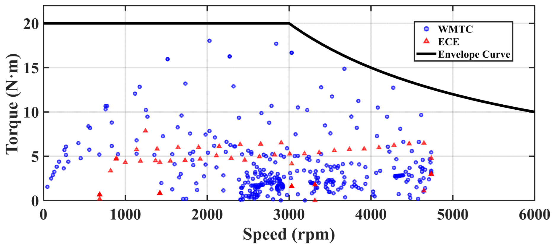
The design and optimization of traction motors for electric vehicles cannot rely solely on nominal operating points, since real-world performance is dictated by dynamic and diverse driving cycles. To ensure realistic evaluation, the torque–speed operating points of the considered three-wheel motorcycle were derived from two standard driving cycles: WMTC and ECE. Using vehicle longitudinal dynamics, the instantaneous torque and speed demand were calculated across the full profile of these cycles.
The resulting operating map demonstrates that the motor predominantly functions within the constant torque region up to around 3000 r/min, after which it transitions into flux-weakening operation. Figure 3 illustrates the complete distribution of the working points together with the required torque–speed envelope curve. This envelope provides the performance boundary that the machine must satisfy throughout the cycles, defining both the peak torque needed for acceleration and the extended speed range required for cruising.
By analyzing the energy distribution across these cycles, the design requirements were aligned with actual driving conditions rather than isolated test points. This approach ensures that the optimized IPM motor achieves high efficiency, improved mileage, and robust performance under representative urban and extra-urban driving scenarios. The derived envelope thus forms the foundation for subsequent clustering, sensitivity analysis, and optimization stages.

3.2. K-Means Clustering for Driving Cycle Representation

To account for the wide range of operating points that occur in standard driving cycles, it is necessary to identify a representative subset that preserves the statistical characteristics of the entire dataset. Direct optimization across all working points is computationally infeasible, so clustering techniques provide an effective alternative. In this study, the k-means algorithm is employed to group the torque–speed operating points obtained from WMTC and ECE cycles into a limited number of clusters. K-means clustering is employed to partition the working points into K clusters by minimizing the sum of squared Euclidean distances between points and their respective cluster centroids. Formally, given a dataset X = { x 1 ,   x 2 ,   ,   x n } where each x i   R 2 represents speed and torque, the clustering problem is expressed as (4).
m i n { C k } k = 1 K x i C k x i μ k 2
where C k denotes the k t h cluster and μ k its centroid computed as (5).
μ k = 1 C k x i C k x i
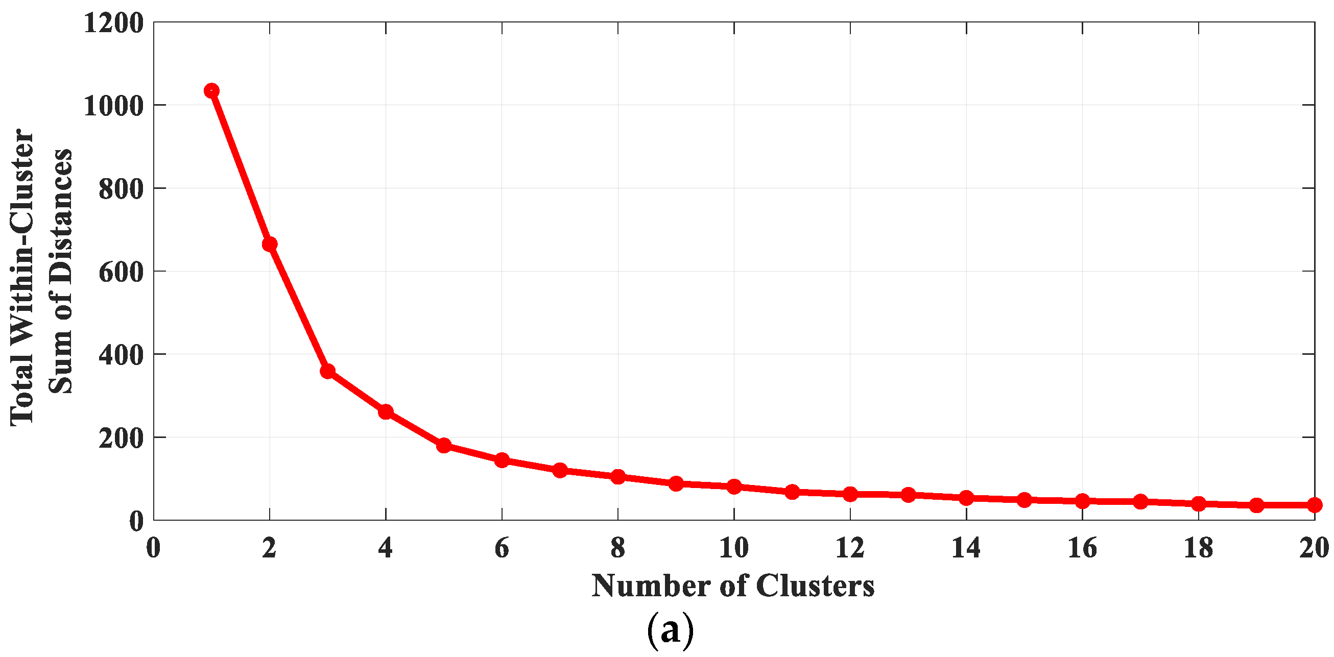
The elbow method was first used to determine the optimal number of clusters. This approach evaluates the sum of squared errors (SSE) between the points in each cluster and their corresponding centroid. As the number of clusters increases, SSE decreases, but beyond a certain point the improvement becomes marginal. The curve of SSE versus cluster number exhibits a clear “elbow,” which indicates the most efficient partitioning of the dataset. Based on this criterion, ten clusters were selected as sufficient to capture the major variations in operating conditions without unnecessary redundancy.
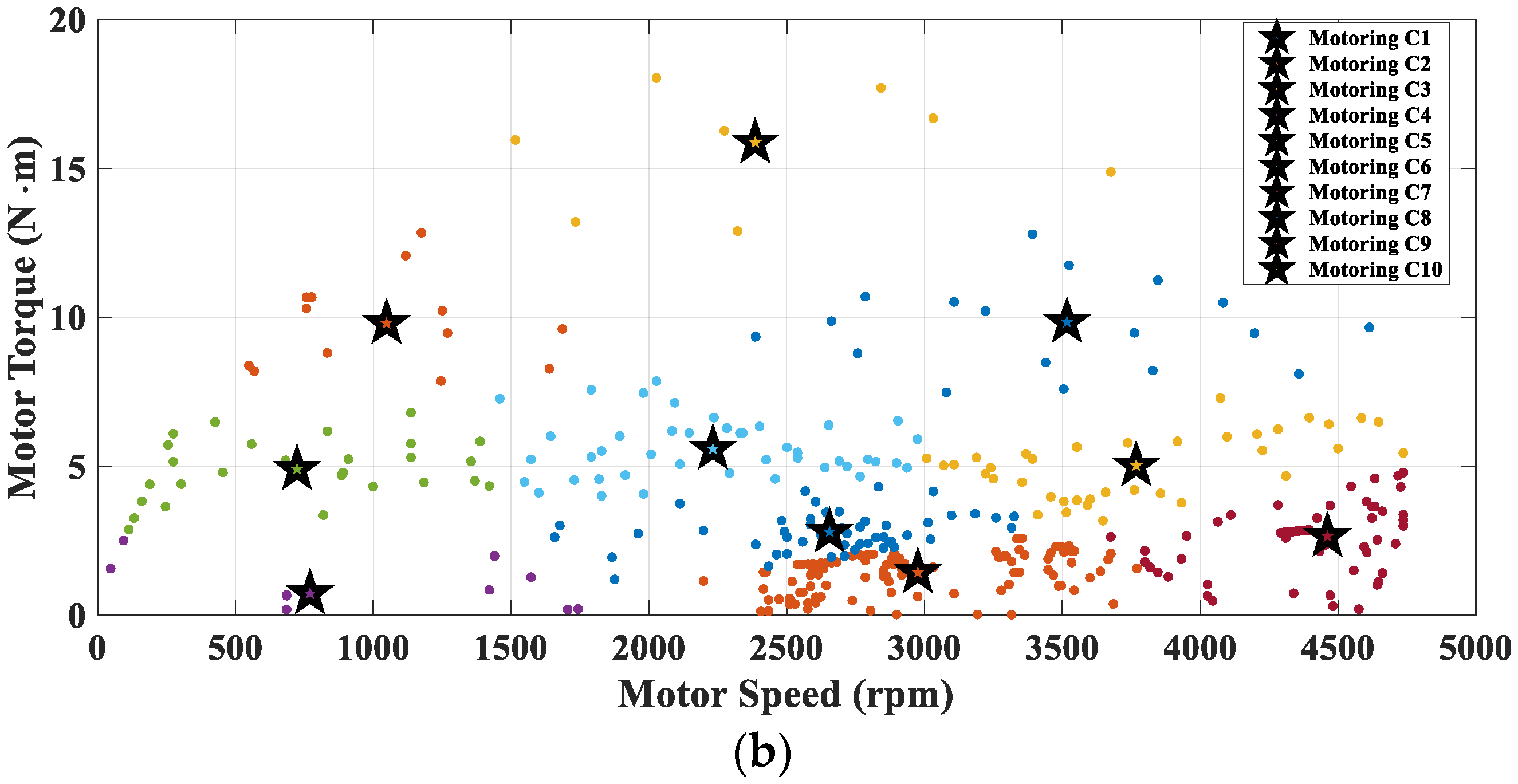
After clustering, the centroid of each cluster was defined as a representative operating point for optimization. Figure 4a shows the elbow criterion used to select the cluster number, while Figure 4b illustrates the resulting partitions of the operating points across the torque–speed map. The detailed parameters of these representative operating points are reported in Table 4.
This clustering strategy substantially reduces the computational burden by replacing thousands of operating points with only ten carefully selected representatives. At the same time, it ensures that the distribution of energy demand and torque–speed coverage of the original driving cycles is faithfully preserved, allowing for reliable evaluation and optimization of the IPM motor under study.

3.3. Optimization Algorithm

The optimization of the IPM motor over a representative driving cycle involves 12 design variables, making conventional methods such as GA or PSO impractical due to their high computational demand. To address this, a Design of Experiments (DOE) strategy was adopted. Among DOE techniques, the Taguchi method was chosen for its efficiency and robustness in handling multi-parameter problems with reduced evaluations [41].
Since Taguchi is originally limited to single-objective problems and discrete parameter levels, two modifications were applied. A weighted-sum formulation enabled multi-objective optimization, while a multi-level refinement approach allowed coarse-to-fine parameter exploration. Further details of this methodology can be found in [42].
The optimization minimizes a composite index F T that combines cost and CE as (6).
F T = ω 1 . C ^ + ω 2 . C E ^ + P
where C ^ and C E ^ are normalized values of machine price and lifetime energy consumption, respectively. Equal weights ( ω 1 = 0.5 and ω 2 = 0.5 ) were assigned. Equal weights were adopted to provide an unbiased baseline trade-off between cost and environmental impact, reflecting a balanced sustainability perspective and aligning with prior multi-objective motor optimization studies. The penalty term P ensures constraint satisfaction: the motor must deliver at least 20 Nm torque and keep the hotspot temperature below 150 °C, evaluated using coupled electromagnetic–thermal analysis.

4. Results

By performing the multi-level optimization algorithm and applying a convergence criterion of 1%, the results have been illustrated in Table 5. The convergence was achieved between the second and third design iterations, where the difference in F T   dropped to just 0.0%, well within the 1% threshold. This confirms that the optimization process had stabilized, indicating that further iterations would yield only marginal improvements. Relative to the initial design, the optimum design delivers simultaneous improvements in both objectives while satisfying all constraints. The machine cost decreases from 74.1 to 72.5 (≈2.16% reduction) and the CE drops from 298.8 to 291.416 (≈2.47% reduction). With equal weights (ω1 = ω2 = 0.5) and no penalty (constraints met: Torqueₚ = 20 Nm, Temperatureₕ = 96.96 °C < 150 °C), the composite index improves from F T = 1.000 (Initial) to F T ≈ 0.9768, i.e., a ≈ 2.32% reduction in the weighted objective. Supporting indicators also move in the right direction: the utilization measure decreases from C E u s e = 0.0318 to 0.0312 (≈1.9% lower). Although hotspot temperature rises modestly (94.84 °C to 96.96 °C), it remains well below the 150 °C limit, confirming that the optimum design achieves a more cost- and energy-efficient solution without violating performance or thermal constraints.
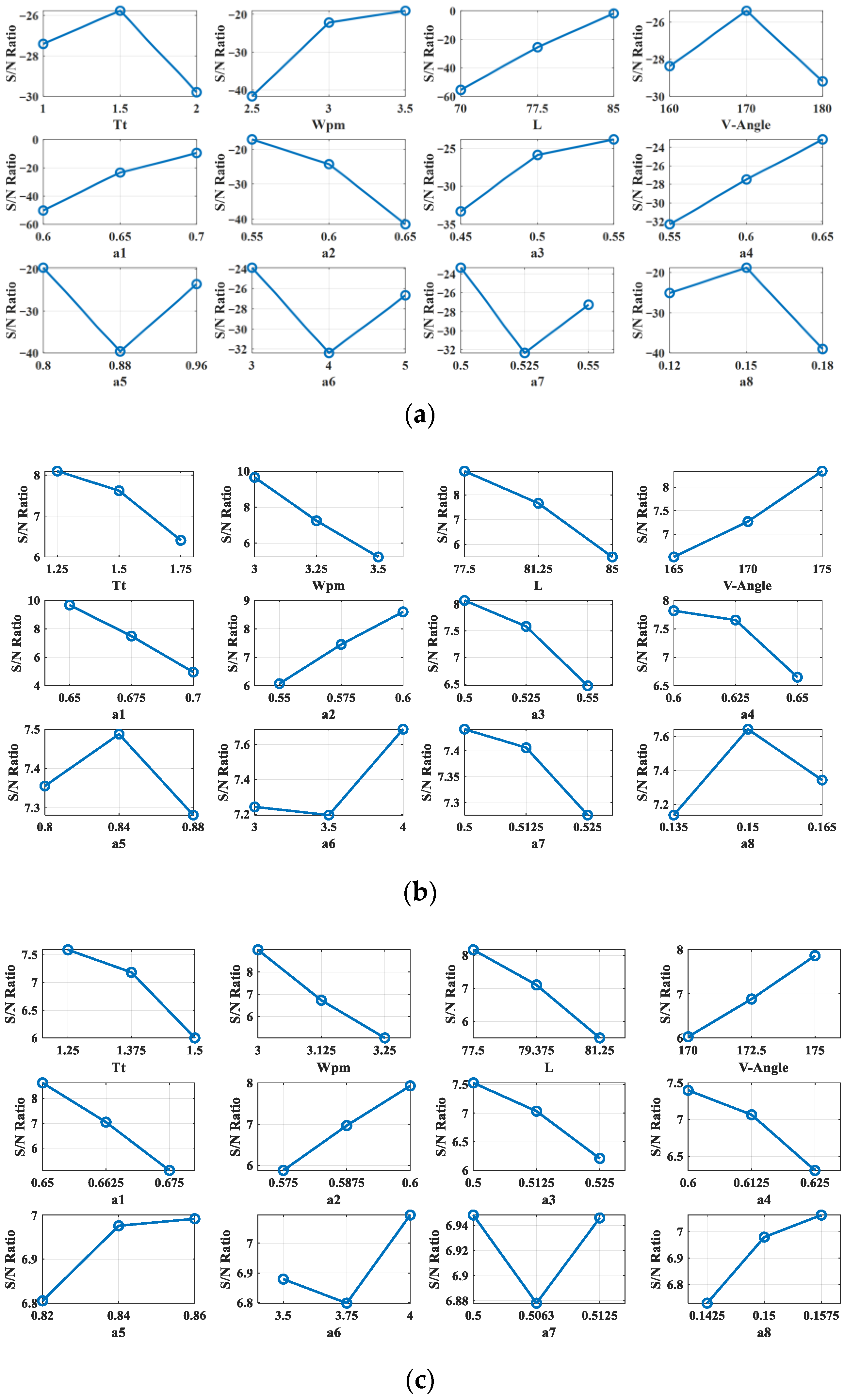
In the iterative optimization process, the S/N ratios gradually shifted from negative to positive values, as illustrated in Figure 5a–c, indicating a continuous improvement in process robustness. As the design space was refined in each iteration, the difference between the lower and higher S/N values for each parameter decreased, reflecting reduced variability and a more stable system response. For example, parameter T t exhibited a remarkable improvement, with its average S/N ratio increasing from −28 dB in the first iteration [Figure 5a] to +7 dB in the second [Figure 5b] and +7.1 dB in the third [Figure 5c]. Furthermore, the range between the lowest and highest S/N values for this parameter decreased from 4.5 dB to 1.9 dB and 1.6 dB in the second and third iterations, respectively, demonstrating enhanced stability and reduced sensitivity to noise. A similar upward trend and narrowing of S/N variation were observed for the other parameters as well, confirming that the multi-level Taguchi approach effectively minimized noise effects, improved consistency, and guided the design toward the most robust and optimal operating conditions.

4.1. Magnetic Flux Density Distribution

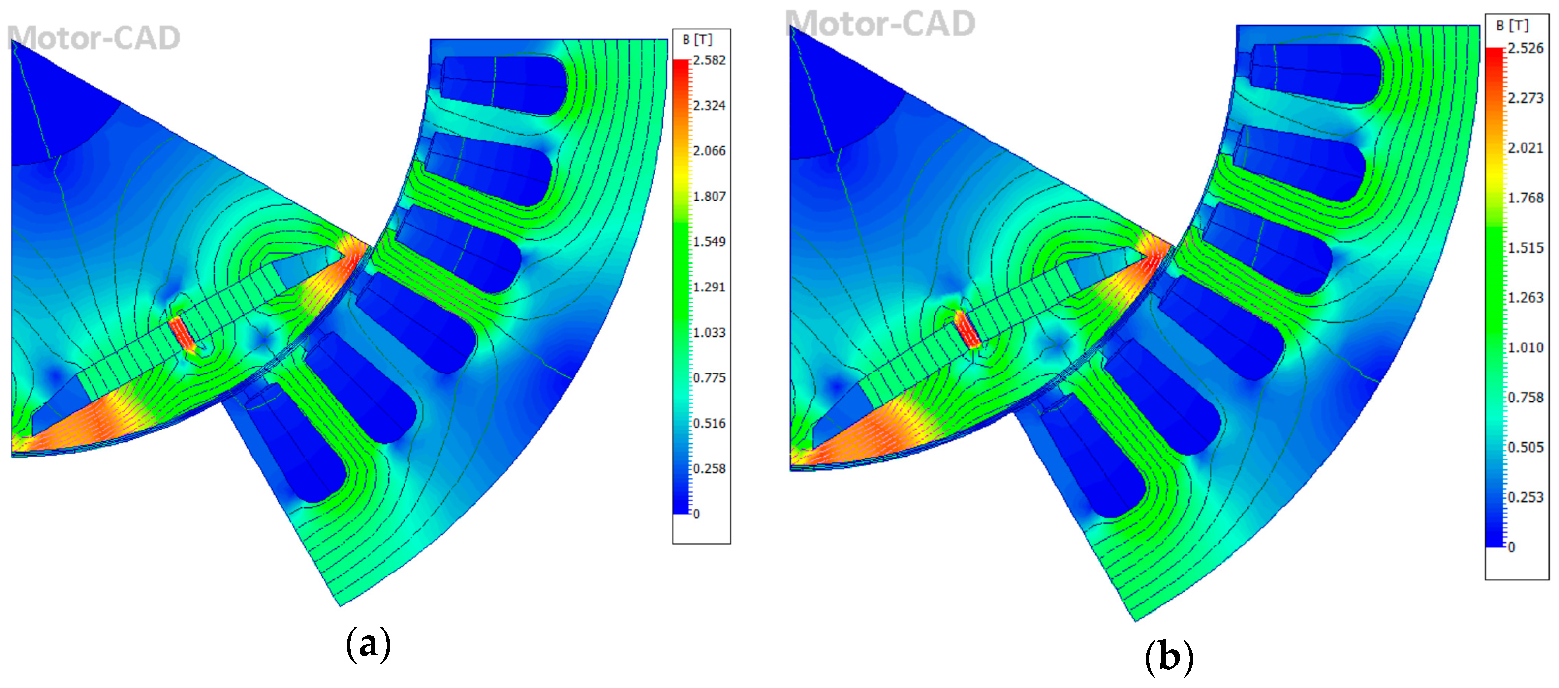
The magnetic flux density distributions of the initial and optimized IPM designs are compared in Figure 6. In the initial design, the peak flux density in the stator tooth was 1.73 T, with an average airgap flux density of 0.7232 T. After optimization, these values change to 1.81 T and 0.6034 T, respectively. The results indicate that both designs remain well within acceptable magnetic limits, indicating that there is no significant oversaturation in critical regions such as the stator tooth and back-iron. This confirms that the optimum design maintains a proper flux density distribution.

4.2. Life Cycle Impact Assessment (LCIA) and Interpretation

Based on the results in Table 6, the optimum design delivers a measurable reduction in life cycle CE relative to the initial design. The total CE falls from 298.8 k g C O 2 e to 291.416 k g C O 2 e (≈2.47% lower), driven by improvements in both the raw-materials and use phases. The raw-material contribution decreases from 62.6 k g C O 2 e to 59.344 k g C O 2 e (≈5.20% reduction), while the use-phase intensity C E u s e declines from 0.0318 k g C O 2 e to 0.0312 k g C O 2 e (≈1.89% reduction), consistent with the efficiency gains reported in the design study. EoL impacts remain negative for both designs, indicating a net credit from recycling/material recovery; however, the magnitude of this credit is slightly smaller in the optimum (−46.98 k g C O 2 e to −46.10 k g C O 2 e ; ≈1.87% less offset). Overall, the LCIA indicates that integrating the optimization with life cycle thinking yields lower life cycle energy demand, with the largest relative improvement arising from raw-material use and a steady, system-level reduction during operation. If converted to greenhouse-gas terms, these CE reductions would translate proportionally given an appropriate electricity emission factor. Although the overall improvement in the composite metric is around 2%, the framework achieves these gains with low computational overhead while enhancing design robustness. Such integrated approaches capture environmental improvements that accumulate across production and use stages, validating their utility despite modest percentage changes.

5. Conclusions

This work presented a multiphysics, LCA-based design optimization framework for IPM traction motors in electric vehicles, integrating driving cycle performance, coupled electromagnetic–thermal constraints, and LCA metrics within a unified optimization. A weighted composite index combined cost and life cycle CE, while a multi-level Taguchi refinement with clustering efficiently explored the design space. The optimum design satisfies all requirements (≥20 Nm torque; hotspot 96.96 °C < 150 °C) and achieves concurrent improvements: cost decreases from 74.1 to 72.5 (≈2.16%), and total life cycle CE from 298.8 to 291.416 (≈2.47%). The phase-wise, raw-material CE drops from 62.6 to 59.344 (≈5.20%), the use-phase intensity declines from 0.0318 to 0.0312 (≈1.9%), and the EoL credit remains negative (−46.98 to −46.10). The composite metric improves by around 2.32%. Iteratively, S/N ratios shift from negative to positive with narrowing spreads, evidencing increased robustness. Overall, the results demonstrate that multiphysics-constrained, LCA-driven optimization can deliver sustainable, high-performance IPM motor designs tailored to realistic EV duty cycles and is readily extensible to broader motor and drive architectures.

Author Contributions

Conceptualization, F.M.; methodology, F.M.; writing—original draft preparation, F.M.; writing—review and editing, E.F.F. and M.C.K.; supervision, V.P. All authors have read and agreed to the published version of the manuscript.

Funding

This research received no external funding.

Data Availability Statement

The data presented in this study are available on request from the corresponding author.

Conflicts of Interest

The authors declare no conflicts of interest.

References

  1. Ortega, A.J.P.; Das, S.; Islam, R.; Kouhshahi, M.B. High-Fidelity Analysis with Multiphysics Simulation for Performance Evaluation of Electric Motors Used in Traction Applications. IEEE Trans. Ind. Appl. 2023, 59, 1273–1282. [Google Scholar] [CrossRef]
  2. Ozer, K.; Yilmaz, M. Design and Optimization of IPMSM for Enhanced Efficiency, Cost Reduction, and Performance in Light Electric Vehicles. IEEE Access 2025, 13, 80621–80636. [Google Scholar] [CrossRef]
  3. Mahmouditabar, F.; Baker, N.J. Design Optimization of Induction Motors with Different Stator Slot Rotor Bar Combinations Considering Drive Cycle. Energies 2024, 17, 154. [Google Scholar] [CrossRef]
  4. Kim, T.K.; Kim, J.H.; Kim, J.H.; Kim, K.C.; Lee, J.H.; Yeo, C.G.; Jung, S.Y. Performance Comparison of Induction Motors and IPMSMs With Identical Stators for Use as Auxiliary Motors in EVs and HEVs. IEEE Trans. Ind. Appl. 2025, 1–11. [Google Scholar] [CrossRef]
  5. Mahmouditabar, F.; Baker, N.J. Robust Design of a Six-Phase Segmented Switch Reluctance Motor Considering Manufacturing Tolerances and Manufacturing Processes. IEEE Access 2024, 12, 160018–160029. [Google Scholar] [CrossRef]
  6. Ajamloo, A.M.; Ghaheri, A.; Ibrahim, M.N.; Sergeant, P. A New Hybrid Permanent Magnet-Assisted Synchronous Reluctance Motor With Efficient Utilization of Rare-Earth Permanent Magnets. IEEE Trans. Energy Convers. 2025, 40, 1325–1338. [Google Scholar] [CrossRef]
  7. Paulraj, T.; Obulesu, Y.P. Comprehensive Performance Evaluation of 60 KW PMSM, EESM, and SynRM for Electric Vehicle Traction Under Steady-State and Drive Cycle Conditions. IEEE Access 2025, 13, 155916–155939. [Google Scholar] [CrossRef]
  8. Sharma, A.; Banchhor, D.K.; Jain, A.K. Interior Permanent Magnet Rotor Notch Optimization for High-Speed Torque Enhancement in Brushless DC Motors. IEEE Trans. Energy Convers. 2025. [Google Scholar] [CrossRef]
  9. Wang, L.; Zhang, X.; Wu, J.; Wang, M.; Hu, W.; Geng, H.; Pang, X. Multi-Objective Optimization Design of a Segmented Asymmetric V-Type Interior Permanent Magnet Synchronous Motor. IEEE Trans. Magn. 2025, 61, 8200312. [Google Scholar] [CrossRef]
  10. Gronwald, P.O.; Kern, T.A. Traction Motor Cooling Systems: A Literature Review and Comparative Study. IEEE Trans. Transp. Electrif. 2021, 7, 2892–2913. [Google Scholar] [CrossRef]
  11. Amini, A.; Farrokh, F.; Mahmouditabar, F.; Baker, N.J.; Vahedi, A. Enhanced Interior PMSM Design for Electric Vehicles Using Ship-Shaped Notching and Advanced Optimization Algorithms. Energies 2025, 18, 4527. [Google Scholar] [CrossRef]
  12. Li, S.; Tong, W.; Wu, S.; Tang, R. General Analytical Model and Experimental Verification for Mechanical Stress of High-Speed Interior Permanent Magnet Motors Considering Modified Rotor. IEEE Trans. Ind. Appl. 2025, 61, 67–76. [Google Scholar] [CrossRef]
  13. Yang, Y.; Sun, X.; Xu, N.; Wan, B.; Yao, M. Design Optimization of a 12/10 Switched Reluctance Motor Considering Target Driving Cycle and Driving Condition. IEEE J. Emerg. Sel. Top. Power Electron. 2025, 13, 5305–5316. [Google Scholar] [CrossRef]
  14. Wang, J.; Zhang, C.; Guo, D.; Yang, F.; Zhang, Z.; Zhao, M. Drive-Cycle-Based Configuration Design and Energy Efficiency Analysis of Dual-Motor 4WD System With Two-Speed Transmission for Electric Vehicles. IEEE Trans. Transp. Electrif. 2024, 10, 1887–1899. [Google Scholar] [CrossRef]
  15. Zhang, Q.; Zhang, Q.; Yu, B.; Yu, J. Online Identification of Parameters and Electromagnetic Torque for Permanent Magnet Synchronous Motors Based on Energy Analysis. In Proceedings of the Conference Record—IAS Annual Meeting (IEEE Industry Applications Society), Taipei, Taiwan, 15–20 June 2025. [Google Scholar] [CrossRef]
  16. Mahmouditabar, F.; Vahedi, A.; Takorabet, N. Design and Analysis of Interior Permanent Magnet Motor for Electric Vehicle Application Considering Irreversible Demagnetization. IEEE Trans. Ind. Appl. 2022, 58, 284–293. [Google Scholar] [CrossRef]
  17. Mahmouditabar, F.; Vahedi, A.; Takorabet, N. Robust Design of BLDC Motor Considering Driving Cycle. IEEE Trans. Transp. Electrif. 2023, 10, 1414–1424. [Google Scholar] [CrossRef]
  18. Fan, D.; Zhu, X.; Quan, L.; Han, P.; Xiang, Z.; Wu, J. Driving Cycle Design Optimization of Less-Rare-Earth PM Motor Using Dimension Reduction Method. IEEE Trans. Energy Convers. 2023, 38, 1614–1625. [Google Scholar] [CrossRef]
  19. Praslicka, B.; Ma, C.; Taran, N. A Computationally Efficient High-Fidelity Multi-Physics Design Optimization of Traction Motors for Drive Cycle Loss Minimization. IEEE Trans. Ind. Appl. 2023, 59, 1351–1360. [Google Scholar] [CrossRef]
  20. Cheng, Y.; Wang, Y.; Ma, J.; Liu, G.; Li, D.; Qu, R. Fast Evaluation of Driving Cycle Efficiency of Interior Permanent Magnet Synchronous Machines for Electric Vehicles Considering Step-Skewing. IEEE Trans. Ind. Appl. 2024, 60, 4396–4407. [Google Scholar] [CrossRef]
  21. Zhu, X.; Jiang, M.; Xiang, Z.; Xu, L.; Chen, Y.; Quan, L. Design and Optimization of a Multi-Region High-Efficiency Permanent Magnet Motor with Enhanced Energy Efficiency. IEEE Trans. Energy Convers. 2025, 40, 2169–2178. [Google Scholar] [CrossRef]
  22. Layek, K.; Nair, S.V.; Hatua, K. A Tapped Winding Interior Permanent Magnet Synchronous Machine for Medium-Duty Delivery Trucks. IEEE Trans. Transp. Electrif. 2024, 10, 7420–7430. [Google Scholar] [CrossRef]
  23. Hoang, K.D.; Yu, A.; Ullah, S.; Valente, G.; Shahaj, A.; Atallah, K. Design, Analysis and Experimental Evaluation of a Novel High-Speed High-Power Ferrite IPM Machine for Traction Applications. IEEE Trans. Ind. Appl. 2024, 60, 5998–6009. [Google Scholar] [CrossRef]
  24. Sahin, H.; Esen, H. Performance and Energy Analysis of a Fuel Cell Electric Vehicle. IEEE Access 2025, 13, 29206–29219. [Google Scholar] [CrossRef]
  25. Rassõlkin, A.; Belahcen, A.; Kallaste, A.; Vaimann, T.; Vyacheslavovich Lukichev, D.; Orlova, S.; Heidari, H.; Asad, B.; Pando Acedo, J. Life Cycle Analysis of Electrical Motor Drive System Based on Electrical Machine Type. Proc. Est. Acad. Sci. 2020, 69, 162–177. [Google Scholar] [CrossRef]
  26. Cassoret, B.; Manata, J.P.; Mallard, V.; Roger, D. Comparative Life Cycle Assessment of Induction Machines Made with Copper-Cage or Aluminium-Cage Rotors. IET Electr. Power Appl. 2019, 13, 712–719. [Google Scholar] [CrossRef]
  27. Keuter, R.J.; Melo, S.P.; Jois, P.K.; Cerdas, F.; Herrmann, C.; Ponick, B. Investigation of Electric Motors For All-Electric Aircraft with Different Material Combinations from an Environmental Perspective. In Proceedings of the 2023 IEEE International Conference on Electrical Systems for Aircraft, Railway, Ship Propulsion and Road Vehicles and International Transportation Electrification Conference, ESARS-ITEC 2023, Venice, Italy, 29–31 March 2023. [Google Scholar] [CrossRef]
  28. Mafrici, S.; Madonna, V.; Maria Meano, C.; Friis Hansen, K.; Tenconi, A. Switched Reluctance Machine for Transportation and Eco-Design: A Life Cycle Assessment. IEEE Access 2024, 12, 68334–68344. [Google Scholar] [CrossRef]
  29. Zhang, X.; Xu, Z.; Gerada, C.; Gerada, D. Carbon Emission Analysis of Electrical Machines. In Proceedings of the ICEMS 2021—2021 24th International Conference on Electrical Machines and Systems, Gyeongju, Republic of Korea, 31 October–3 November 2021; pp. 1678–1683. [Google Scholar] [CrossRef]
  30. Boughanmi, W.; Manata, J.P.; Roger, D. Contribution of LCA Approach to the Choice of Rotating Electrical Machines for Environmental Impact Minimization. In Proceedings of the 2012 20th International Conference on Electrical Machines, ICEM 2012, Marseille, France, 2–5 September 2012; pp. 122–128. [Google Scholar] [CrossRef]
  31. Schillingmann, H.; Gehler, S.; Henke, M. Life Cycle Assessment of Electrical Machine Production Considering Resource Requirements and Sustainability. In Proceedings of the 2021 11th International Electric Drives Production Conference, EDPC 2021, Erlangen, Germany, 7–9 December 2021. [Google Scholar] [CrossRef]
  32. Wrobel, R.; Rajaeifar, M.A.; Mecrow, B. Life Cycle Assessment of Electrical Machines—A Case Study. In Proceedings of the 2024 IEEE Energy Conversion Congress and Exposition, ECCE 2024, Phoenix, AZ, USA, 20–24 October 2024; pp. 5611–5618. [Google Scholar] [CrossRef]
  33. Zhang, X.; Xu, Z.; Zhang, F.; Darmani, M.A.; Jiang, J.; Gerada, C.; Gerada, D. Carbon Emission Evaluation and Comparison for Different Electric Machines. In Proceedings of the 2024 27th International Conference on Electrical Machines and Systems (ICEMS), Fukuoka, Japan, 26–29 November 2024; pp. 3158–3164. [Google Scholar] [CrossRef]
  34. Mahmouditabar, F.; Baker, N. A Review on the Effect of Electrical Steel Manufacturing Processes on the Performance of Electric Machines. Energies 2023, 16, 7954. [Google Scholar] [CrossRef]
  35. ISO 14040; Environmental Management—Life Cycle Assessment—Principles and Framework. International Organization for Standardization: Geneva, Switzerland, 2006.
  36. ISO 14044; Environmental Management—Life Cycle Assessment—Requirements and Guidelines. International Organization for Standardization: Geneva, Switzerland, 2006.
  37. Shenoy, A.A.; Miller, C.; Brunnert, D.; Verma, M. Enhancing Success in Carbon Capture Integration with Existing Industrial Facilities: Electrical Challenges and Strategies. IEEE Trans. Ind. Appl. 2025, 61, 6781–6789. [Google Scholar] [CrossRef]
  38. Ecoinvent—Data with Purpose. Available online: https://ecoinvent.org/ (accessed on 11 October 2025).
  39. What Are Emission Factors in Carbon Accounting? Available online: https://plana.earth/academy/emission-factors (accessed on 31 October 2025).
  40. GOV.UK Greenhouse Gas Reporting: Conversion Factors 2023. Available online: https://www.gov.uk/government/publications/greenhouse-gas-reporting-conversion-factors-2023 (accessed on 31 October 2025).
  41. Cao, J.; Zhu, W.; Yang, L.; Li, D.; He, X.; Jia, B.; Chen, S.; Yin, C. Electromagnetic Design and Taguchi Method Optimization of High-Speed Permanent Magnet Motors for Air Compressors. In Proceedings of the 2025 17th International Conference on Computer and Automation Engineering, ICCAE 2025, Perth, Australia, 20–22 March 2025; pp. 502–506. [Google Scholar] [CrossRef]
  42. Mahmouditabar, F.; Baker, N.J. Robust Design of Induction Machines for High-Speed Electric Freight Locomotive Applications. IEEE Access 2024, 12, 38786–38800. [Google Scholar] [CrossRef]
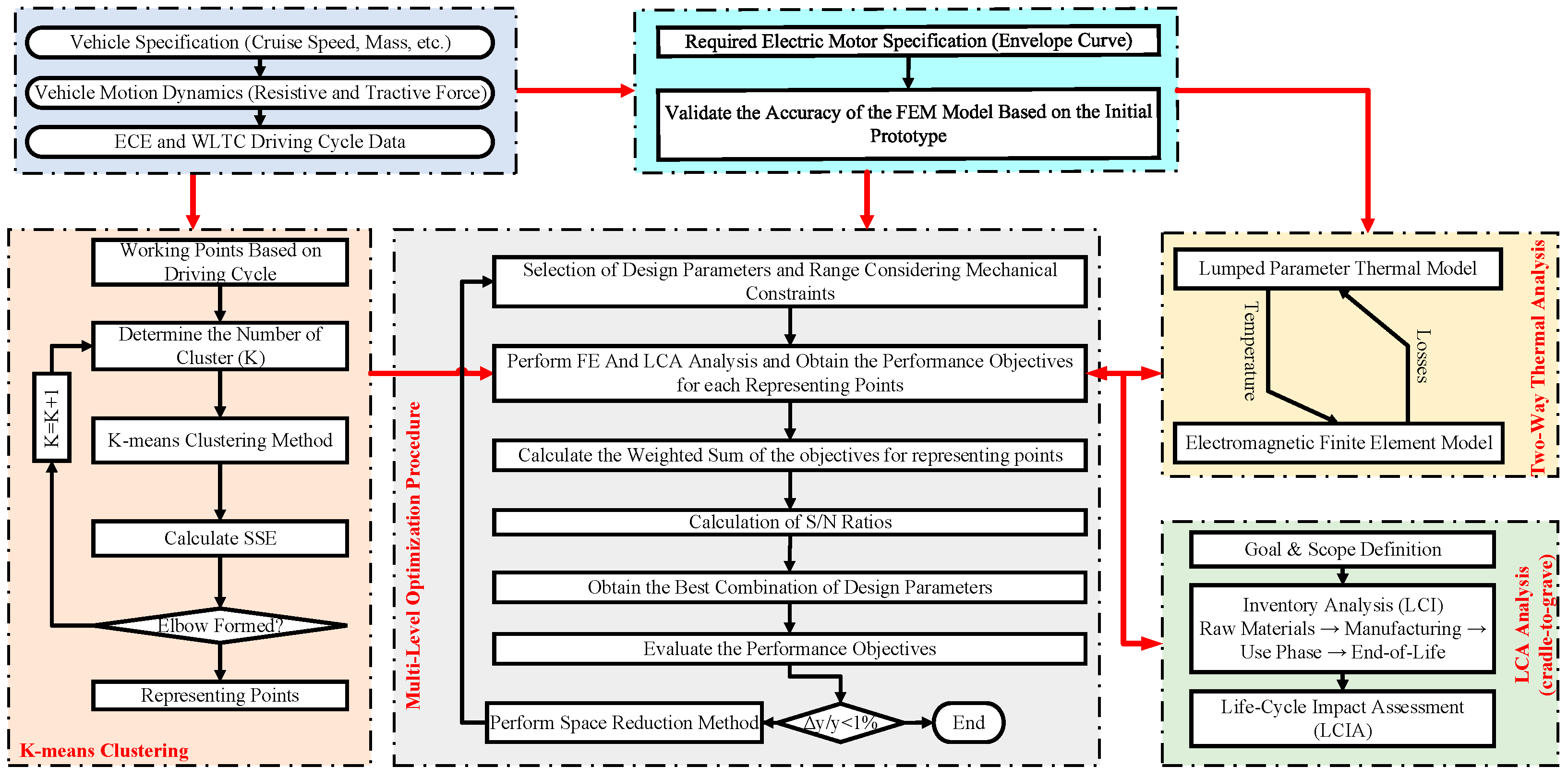
Figure 1. Methodological framework for the integrated design–LCA optimization of the IPM motor.
Energies 18 06167 g001
Figure 2. (a) IPM motor prototype and (b) experimental results.
Energies 18 06167 g002
Figure 3. The whole working point of the WMTC and ECE driving cycle and the envelope curve of the required electric motor.
Energies 18 06167 g003
Figure 4. (a) The optimum number of k-means clusters and (b) the detail of the clusters and representing points.
Energies 18 06167 g004aEnergies 18 06167 g004b
Figure 5. Signal-to-noise (S/N) ratio plots for three successive Taguchi iterations: (a) Iteration 1, (b) Iteration 2, and (c) Iteration 3.
Energies 18 06167 g005
Figure 6. Magnetic flux density (a) Initial and (b) Optimum.
Energies 18 06167 g006
Table 1. Details of the Designed IPM Motor.
ParameterValueParameterValue
Nominal power2 kWStator laminationM800
DC bus voltage72 VStator slot36
Fill factor0.35Pole number6
MagnetN42Stator outer diameter124
Axial length160 mmStator inner diameter80 mm
Magnet length3 mmMagnet width10 mm
Table 2. A detailed breakdown of the CE contributions by component [38].
ComponentMaterial E F i R i η i
StatorM800-50A2.20.90.92
RotorM800-50A2.20.90.92
HousingAluminum18.60.930.95
End CapsAluminum18.60.930.95
Stator WindingCopper60.650.9
Permanent MagnetN4231.40.010.5
InsulationNomex600
ShaftCK451.370.950.95
ImpregnationEpoxy5.0900
BearingSteel4.620.950.95
Table 3. Variation Range of Geometry Parameters.
ParameterSymbolVariation Range
Stator outer diameter (mm) D o r 125
Airgap (mm) l g 0.65
Tooth Tip Depth T t [1 2]
Magnet thicknessM[2.5 3.5]
Axial length (mm) L [75 85]
V-angle θ 1 [160 180]
The ratio of stator bore to stator diameter α 1 [0.6 0.7]
The ratio of slot depth to stator lam thickness α 2 [0.55 0.65]
The ratio of tooth width (radian) to slot pitch α 3 [0.45 0.55]
The ratio of slot opening to max slot opening α 4 [0.55 0.65]
The ratio of pole arc to max pole arc α 5 [0.8 0.9]
The ratio of web thickness to max web thickness α 6 [0.8 1]
The ratio of V web bar width to max V web bar width α 7 [0.5 0.55]
The ratio of Web length to max Web length α 8 [0.12 0.18]
Table 4. The details of the representing points.
Cluster NumberSpeed (rpm)Torque (Nm.)Cluster Weight
135169.8319
229751.43150
337675.0237
47700.7290
57234.9027
622325.5844
744612.6475
826552.7952
910489.8013
10238515.8611
Table 5. Optimization Results.
No. C E r a w C o s t E o L T o r q u e p C E u s e C E T e m p e r a t u r e h F T
Initial62.674.1−46.98200.0318298.894.841
163.28880.5−47.97200.0316296.324120.681.039
259.34472.5−46.1200.0312291.41696.9580.9768
359.34472.5−46.1200.0312291.41696.9580.9768
Table 6. CE comparison of designed traction motors over life cycle phases.
DesignRaw Material ( k g C O 2 e )Use-Phase ( k g C O 2 e )EoL ( k g C O 2 e )
Initial62.6283.1−46.98
Optimum59.3278.1−46.1
Disclaimer/Publisher’s Note: The statements, opinions and data contained in all publications are solely those of the individual author(s) and contributor(s) and not of MDPI and/or the editor(s). MDPI and/or the editor(s) disclaim responsibility for any injury to people or property resulting from any ideas, methods, instructions or products referred to in the content.