Article

A Fuzzy Division Control Strategy for Flywheel Energy Storage to Assist Primary Frequency Regulation of Hydropower Units

1
State Grid Gansu Electric Power Company Construction Branch, Lanzhou 730000, China
2
State Grid Gansu Electric Power Company Wuwei Power Supply Company, Wuwei 733000, China
3
State Grid Gansu Electric Power Company Lanzhou Power Supply Company, Lanzhou 710061, China
4
State Grid Gansu Electric Power Company Linxia Power Supply Company, Linxia 731199, China
5
State Key Laboratory of Eco-Hydraulic in Northwest Arid Region, Xi’an University of Technology, Xi’an 710048, China
*
Author to whom correspondence should be addressed.
Energies 2025, 18(22), 6032; https://doi.org/10.3390/en18226032
Submission received: 10 October 2025 / Revised: 6 November 2025 / Accepted: 14 November 2025 / Published: 19 November 2025
(This article belongs to the Section D: Energy Storage and Application)

Abstract

Enhancing the flexibility of hydropower units is essential for adapting to future power systems dominated by intermittent renewable energy sources such as wind and solar, which introduce significant frequency stability challenges due to their inherent variability. To improve the primary frequency regulation capability of the hydropower unit, this study incorporates a flywheel energy storage system—known for its fast response and high short-term power output. Using fuzzy control theory, a frequency regulation command decomposition method with a variable filtering time constant is proposed. In this fuzzy control design, the frequency change rate and the state of charge of the flywheel energy storage are used as inputs to dynamically adjust the filtering time constant, which serves as the output. Additionally, a logistic function is introduced to constrain the output power of the flywheel energy storage under different states of charge, ensuring operational safety and durability. Based on these techniques, a fuzzy frequency division control strategy is designed for flywheel-assisted hydropower primary frequency regulation. Simulation results show that the integration of flywheel energy storage significantly improves the primary frequency regulation performance of the hydropower unit. Compared to the system without energy storage, the proposed strategy reduces the maximum frequency deviation by 53.49% and the steady-state frequency deviation by 39.06%, while also markedly decreasing fluctuations in hydropower output. This study offers both a theoretical basis and practical guidance for enhancing the operational flexibility of hydropower systems.

1. Introduction

Currently, with the rapid development of intermittent renewable energy sources (RES) such as wind and solar power, the structure of the power system is undergoing profound transformations [1,2,3]. As a crucial regulating power source for the grid, hydropower will undertake more tasks to compensate for fluctuations caused by the integration of RES [4,5]. It has become an urgent research issue to enhance regulating capacity while alleviating operational pressure on the hydropower unit (HPU) [6].
Numerous scholars have conducted extensive research on regulation methods and control parameter optimization of HPUs, achieving fruitful results. Liu et al. [7] proposed a particle swarm optimization-based fuzzy Proportional–Integral–Derivative (PID) approach for parameter tuning of hydropower units to enhance frequency regulation capabilities. Dong et al. [8] adopted an improved quantized damping method, recording the variations in settling time and damping coefficients under different PID parameters and operating conditions, which revealed the contradictory relationship between regulation performance and damping characteristics. Jia et al. [9] proposed a novel control strategy termed the center-frequency-structured governor-side power system stabilizer. By establishing a transfer function model of a hydropower unit equipped with a PID governor, and through analysis of damping torque and amplitude–frequency characteristics, the dominant factors and key characteristics of ultra-low-frequency oscillations were revealed. This study provides an effective technical means to enhance the reliability of hydraulic turbines and guide the safe and stable operation of hydropower-dominated systems. Liu et al. [10] proposed a governor parameter optimization strategy based on the crayfish optimization algorithm, which rapidly obtains optimal PID parameters for the hydropower unit regulation system controller, providing strong support for PID parameter tuning. Chen et al. [11] selected the control mode by comparing the damping characteristics of different governor control modes, then proposed a correlation coefficient index to identify generators sensitive to ultra-low frequency oscillations, subsequently optimized PID parameters based on a new performance criterion considering the governor’s damping characteristics, and finally developed optimization strategies that were implemented in the Southwest China Power Grid, demonstrating excellent performance. Lu et al. [12] investigated the relationship between multi-frequency oscillation characteristics and parameters of hydro-turbine governing systems, and constructed an integrated optimization strategy incorporating both ultra-low-frequency oscillations safety and regulation performance constraints. However, these studies primarily focus on optimizing the governor parameters or control structures of the hydro-turbine governing system itself. While these approaches can improve regulation performance to some extent, they face inherent limitations: the optimization effects are constrained by the slow mechanical response of hydraulic turbines, and the fundamental contradiction between regulation performance and damping characteristics remains challenging to resolve completely. Furthermore, these methods generally lack the capability for rapid power compensation, making them inadequate for addressing frequency fluctuations caused by high-penetration renewable energy integration.
To overcome these limitations, researchers have begun exploring the integration of energy storage systems with hydropower units. Battery energy storage systems (BESS) have demonstrated potential in enhancing hydropower regulation capabilities. Liao et al. [13] demonstrated the theoretical feasibility of battery energy storage systems participating in the primary frequency regulation (PFR) of HPUs from the perspectives of frequency domain and time domain simulations, providing support for the flexibility transformation of hydropower systems. Feng et al. [14] established a power system frequency dynamic response model with BESS assisting HPUs in frequency regulation and adopted a two-stage control strategy. Their study demonstrated that the combined operation of BESS and HPUs can significantly improve regulation performance, providing significant economic and technical benefits for the power system. Ojo et al. [15] proposed a frequency controller that adopts a rate-of-change of frequency and frequency-Watt-based composite control strategy to generate active power commands, enhancing the response performance of standalone small hydropower plants via BESS. Gerini et al. [16] employed a double-layer model predictive control technique to integrate a BESS with a run-of-river hydropower plant. They conducted reduced-scale experiments on a unique testing platform, validating the effectiveness of the proposed model predictive control method by comparing different control strategies and the performance under various BESS sizes. Shu et al. [17] adopted a collaborative control method using photovoltaic and hybrid BESS to compensate for the water hammer effect. By employing a strategy based on the whale optimization algorithm to optimize model predictive control, they identified the optimal PID parameters for the hydropower unit, effectively suppressing fluctuations in turbine mechanical power and system frequency. However, BESS applications face several inherent constraints: limited cycle life requiring frequent replacement, safety concerns related to thermal runaway, and environmental issues associated with disposal. These factors significantly increase the long-term operational costs and maintenance requirements, particularly for frequent regulation applications.
Compared to BESS, flywheel energy storage system (FESS) offers distinct advantages for frequency regulation applications, including exceptionally fast response, high power density, virtually unlimited cycle life, and minimal environmental impact [18]. While FESS has been successfully applied in thermal power applications [19,20], its potential in supporting hydropower units for enhanced frequency regulation remains insufficiently explored. Previous research has neither thoroughly investigated the coordinated operation between FESS and HPU nor developed specialized control strategies that leverage their complementary characteristics.
Therefore, to address the research gap in FESS-assisted hydropower frequency regulation, this paper establishes a comprehensive model of FESS supporting conventional HPUs in PFR and proposes a novel coordinated control strategy. The main objectives of this study are:
(1)
To develop an adaptive frequency division control strategy based on fuzzy logic that dynamically allocates power commands between FESS and HPU;
(2)
To design a state of charge (SOC)-based output limitation mechanism for FESS that prevents over-charge/discharge while maintaining regulation capability;
(3)
To verify through simulations that the proposed strategy can significantly improve the primary frequency regulation performance while reducing the operational pressure on hydropower units.

2. A Model of FESS-Assisted HPU for PFR

The schematic diagram of the PFR principle of the power system is shown in Figure 1. In Figure 1, Δ P L is the load power change; Δ P V is the governor output; Δ P m is the prime mover output mechanical power; P c is the unit target power; δ is the speed variation rate, and for hydraulic turbines, δ generally ranges from 2% to 4%.

2.1. HPU Model

The hydraulic turbine and water conveyance system model adopts a linear mathematical model suitable for small disturbance transient processes. Within a certain range, the torque equation and flow equation of the hydraulic turbine are linearized and expressed in incremental relative values as:
Δ m t = e y Δ y + e h Δ h + e x Δ x Δ q = e q y Δ y + e q h Δ h + e q x Δ x
where Δ m t , Δ q are the increments of torque and flow relative values; Δ y , Δ h , Δ x are the increments of guide vane opening, head, and speed relative values; e y , e x , e h , e q y , e q x , e q h are the partial differential coefficients of hydraulic turbine output torque and flow with respect to opening, speed, and head. This paper selects the most common type of Francis turbines found in medium-to-high head hydropower plants participating in frequency regulation. For Francis turbines, take e q x = 0 , and e x is merged with the generator load regulation coefficient.
The water conveyance system uses a rigid water hammer model, the equation is:
Δ h Δ q = T w s
where T w is the water starting time constant, generally 0.05~2 s.
Combining, the transfer function of the hydraulic turbine is obtained as [21]:
G t ( s ) = e y 1 e T w s 1 + e q h T w s
where e = e h × e q y / e y e q h .
At rated conditions, generally e y = 1.0 , e h = 1.5 , e q y = 1.0 , e q h = 0.5 , the hydraulic turbine transfer function is:
G t ( s ) = 1 T w s 1 + 0.5 T w s
The hydropower unit governor model is:
G r ( s ) = 1 T g s + 1
where T g is the governor time coefficient, generally 0.05~0.25 s.
The generator and loads adopt a first-order simplified model, ignoring the electromagnetic transient process of the generator unit, the equation is:
G g ( s ) = 1 H s + D
where H is the generator inertia time constant, typically ranging from 3 to 12 s; D is the generator damping coefficient considering the load regulation effect, generally between 0.5 and 1.5.

2.2. FESS Model

FESS adopts a virtual droop control method as its control method for participating in PFR, as shown in Figure 2. In Figure 2: Δ f is the frequency change, Hz; K F is the FESS frequency regulation coefficient; P F is the power value that should be output by FESS, MW; P F is the actual output power value of the FESS, MW.
To analyze the power output characteristics of FESS as a frequency regulation resource, a first-order inertia model is used as the equivalent model of FESS. This model can simplify analysis and maintain high simulation accuracy. Its transfer function is:
G F ( s ) = 1 1 + s T F
where T F is FESS response time constant.
The state of charge monitoring system judges the current state of charge by monitoring the real-time output power of FESS and transmits it to the output power control system for follow-up adjustment. The S O C calculation formula is:
S O C = S O C 0 0 t P F d t E
where S O C 0 is the initial state of charge of FESS; E is the total stored energy of FESS, MWh.
The change in flywheel state of charge can be obtained according to the change in flywheel mechanical rotational angular velocity. The specific formula is:
S O C = ω ω min 2 ω max 2 ω min 2
where ω is the rotational angular velocity of FESS, rad/s; ω min , ω max are the minimum and maximum rotational angular velocities of the flywheel, rad/s, respectively. This equation shows that FESS corresponds to S O C values of 0 and 1 at maximum and minimum speeds, respectively.
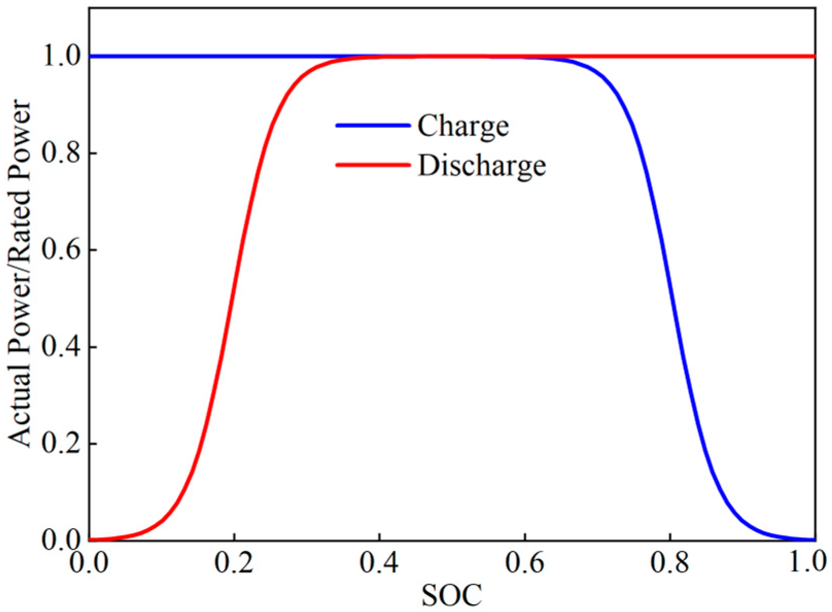
The FESS output power control system comprehensively determines the actual demand value of FESS output based on the current S O C of FESS and the power value required by the system. Simultaneously, to ensure that the charge/discharge characteristics of the energy storage system match the real charge/discharge curves, and to prevent irreversible damage caused by overcharging and over discharging while ensuring energy storage, the logistic regression equation is used to correct FESS output power value, thereby achieving control over FESS output power [22]. The specific expressions are:
P d = K P m P × exp ( r × ( S O C S O C min ) b ) K + P 0 × exp ( r × ( S O C S O C min ) b )
P c = K P m P × exp ( r × ( S O C max S O C ) b ) K + P 0 × exp ( r × ( S O C max S O C ) b )
where P d is the discharge power, MW; P c is the charge power, MW; P m is the rated power, MW; S O C max is the allowed maximum state of charge value; S O C min is the allowed minimum state of charge value; K , P , P 0 , b , r are constants; the specific values are 6, 1/600, 0.01, 0.4, and 13, respectively.
Figure 3 shows a schematic diagram of battery charge/discharge simulation using a logistic function, which enables smooth charging and discharging throughout the entire state of charge range while effectively minimizing the risks of overcharging and over-discharging.

3. Control Strategy for PFR of FESS-Assisted HPU

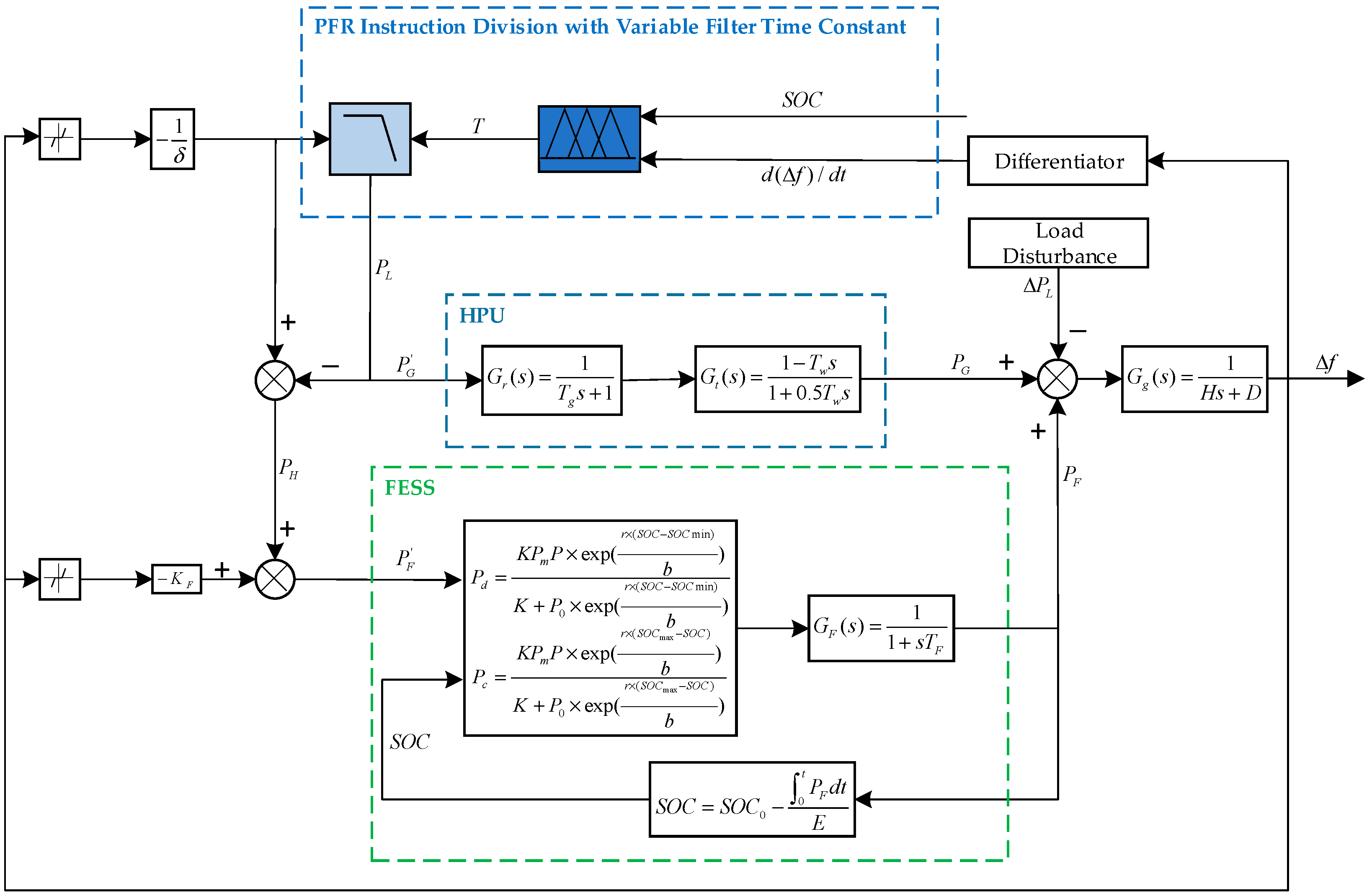
To address the issue of significant fluctuations in the PFR of HPU caused by the large-scale integration of renewable energy, this paper establishes a flywheel energy storage-assisted PFR for HPU and proposes a corresponding control strategy. This strategy includes the decomposition of PFR commands with variable filtering time constants under fuzzy logic control, and the constraint of FESS output power based on different states of charge using a logistic function. The overall control framework is illustrated in Figure 3. In Figure 4: d ( Δ f ) / d t is the system frequency change rate; T is the filter time constant, s; P L is the low-frequency signal; P H is the high-frequency signal.

3.1. PFR Instruction Division with Variable Filter Time Constant

The decomposition of the PFR instruction is completed by a first-order filter. The specific expression form of the first-order filter is:
F ( s ) = 1 T s + 1
Conventional filters, which employ fixed time parameters and cutoff frequencies, lack adaptive filtering characteristics. When HPU and FESS collaborate in grid frequency regulation, such filters struggle to simultaneously accommodate the inherent inertial response characteristics of HPU and the dynamic power compensation requirements of FESS. HPU is suitable for slow, large-magnitude power adjustments, while FESS, with rapid power response capability, is better suited for suppressing high-frequency, small-magnitude power fluctuations. If fixed-parameter filtering strategies continue to be used, it becomes impossible to flexibly define the allocation boundaries of high- and low-frequency power commands according to dynamic system conditions, thereby limiting the coordination efficiency of the two frequency regulation resources.
To address this, this paper proposes treating the filter time constant as an adjustable parameter and establishes a dynamic adjustment mechanism based on fuzzy logic. This fuzzy controller takes the system’s rate of change of frequency and SOC as input variables. Through established fuzzy inference rules, it achieves real-time optimization and adjustment of the filter time constant. When the system frequency change rate is large and the flywheel’s SOC is within a suitable range, the controller automatically reduces the time constant, thereby increasing the filter cutoff frequency. This allocates more high-frequency power components to FESS, enhancing its ability to suppress transient disturbances. Conversely, when frequency fluctuations are gentle or the flywheel’s SOC approaches its operational limits, the time constant is increased, lowering the cutoff frequency. This shifts more power regulation tasks to HPU, ensuring the operational safety of FESS.
Through this approach, the filter’s time constant is no longer fixed but dynamically adjusted according to system states. This enables functional complementarity and coordination between HPU and FESS in the frequency domain. This strategy significantly enhances the combined system’s ability to smooth power fluctuations and its level of frequency adaptability, achieving both robustness and dynamic performance.

3.2. Fuzzy Controller Design

This paper uses a fuzzy controller to realize the dynamic adjustment of the filtering time constant with the system state, and this section presents the specific design method [23,24]. The relationship between the output power of HPU and the frequency change is shown in Equation (13):
Δ P G = 1 δ × Δ f
When the frequency change rate | d ( Δ f ) / d t | increases, load fluctuations are severe, frequency regulation demand increases, and the filter time constant T should be increased, allowing FESS to undertake more frequency regulation tasks, thereby smoothing the output of HPU; when the frequency change rate | d ( Δ f ) / d t | decreases, load fluctuations are gentle, frequency regulation demand decreases, and the filter time constant T should be decreased, reducing the output of FESS, thereby avoiding waste of energy storage resources.
Simultaneously considering S O C : when the frequency change rate d ( Δ f ) / d t > 0 and its absolute value is large, the flywheel needs to charge to absorb excess power generated by the unit. The flywheel is suitable for charging when S O C is low. At this time, the filter time constant should be increased; when the frequency change rate d ( Δ f ) / d t < 0 and its absolute value is large, the flywheel needs to discharge significantly to supplement the power shortage of the unit. However, facing a flywheel with low S O C , to avoid irreversible damage caused by deep discharge, the filter time constant should be decreased.
Based on the above discussion, using d ( Δ f ) / d t and S O C as two control variables, and the filter time constant T as the controlled variable, a two-input, single-output fuzzy controller is designed. The fuzzy domain for frequency change rate d ( Δ f ) / d t is [−0.01, 0.01], with fuzzy subsets {NB, NS, NZ, PZ, PS, PB}; the fuzzy domain for S O C is [0, 1], with fuzzy subsets {NB, NS, ZE, PS, PB}; the fuzzy domain for filter time constant T is [0, 10], with fuzzy subsets {NB, NM, NS, NZ, PZ, PS, PM, PB}; The membership functions of the input and output variables are shown in Figure 5, and the fuzzy control rules are shown in Table 1.

3.3. FESS Output Control

To prevent irreversible damage to FESS caused by overcharging or over-discharging, this section proposes a FESS output control strategy based on the logistic function. Meanwhile, a dead band of ±0.033 Hz is incorporated into the control system to minimize frequent charging and discharging triggered by minor grid frequency fluctuations. The participation of FESS in PFR is primarily divided into two modes: inactivity within the energy storage dead band and charging or discharging to participate in grid frequency regulation when the frequency exceeds the dead band.
(1)
Δ f 0.033 Hz
Since the system frequency deviation signal is within the range set by the energy storage dead zone, FESS does not act and does not participate in primary frequency regulation.
(2)
Δ f < 0.033 Hz
At this time, the active torque of the hydraulic turbine is less than the resistance torque of the generator and exceeds the set dead zone value. FESS should discharge to supplement the power shortage of the unit.
When S O C 0.4 , the flywheel S O C is sufficient. At this time, the actual output power value of FESS is
P F = min P F , P m
When S O C < 0.4 , S O C is insufficient and it is not suitable to discharge at the rated power. The output based on the logistic equation needs to be used. Therefore, the actual output power value of FESS at this time is
P F = min ( P F , P d ) = min ( P F , K P m P × e r × s o c b K + P 0 × e r × s o c b )
(3)
Δ f > 0.033 Hz
At this time, the active torque of the hydraulic turbine is greater than the resistance torque of the generator and exceeds the set dead zone value. The flywheel energy storage should charge to absorb the excess power of the unit.
When S O C 0.6 , the remaining S O C is sufficient. At this time, the actual output power value of FESS is
P F = min P F , P m
When S O C > 0.6 , the flywheel S O C is already close to the maximum value and it is not suitable to charge at the rated power. The output based on the logistic equation needs to be used. Therefore, the actual output power value of FESS at this time is
P F = min ( P F , P c ) = min P F , K P m P × e r × ( 1 S O C ) b K + P 0 × e r × ( 1 S O C ) b

4. Simulation Analysis

Based on the control structure shown in Figure 4, a simulation model of FESS assisting HPU in primary frequency regulation is developed in MATLAB/Simulink (R2024a). The specific parameters are shown in Table 2 [25]. The rated power output of the HPU is 100 MW, and FESS is configured with a capacity of 5 MW/0.125 MWh. For two typical operating conditions (step disturbance and continuous disturbance), a comparative analysis is conducted for (1) the system without energy storage, (2) the flywheel-assisted HPU using virtual droop control, and (3) the flywheel-assisted HPU using fuzzy frequency division control. This analysis comprehensively evaluates the ability of FESS to enhance the PFR capability of HPU and verifies the effectiveness of the proposed control strategy.

4.1. Step Disturbance

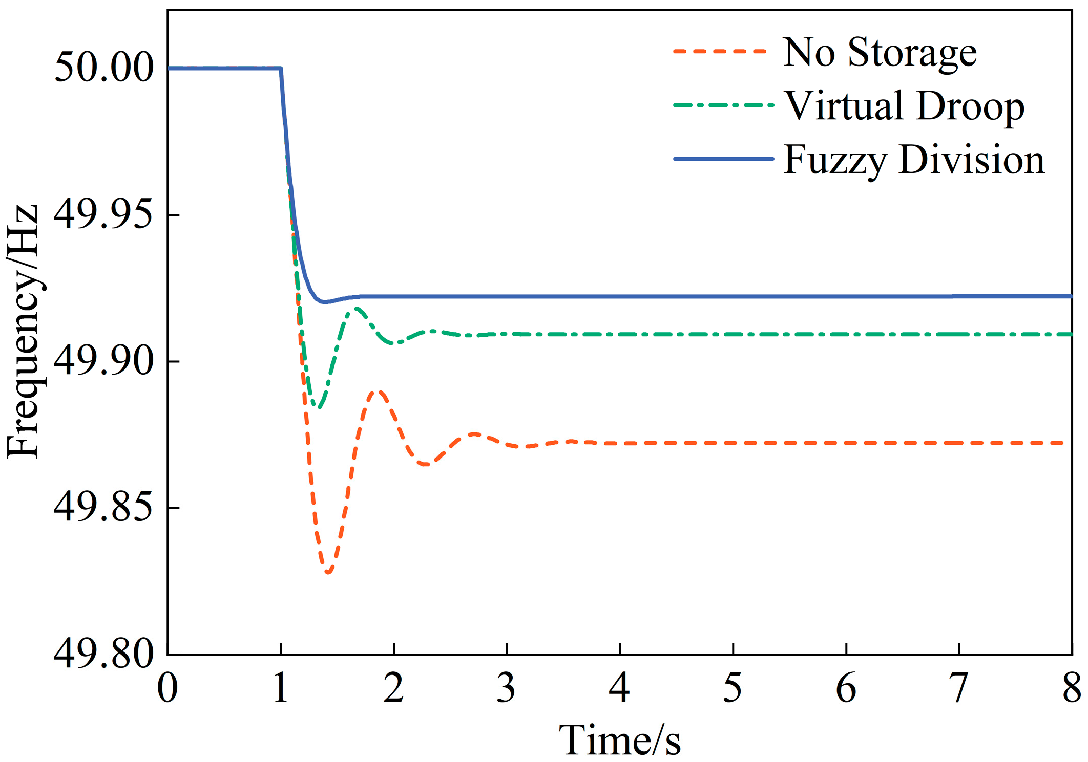
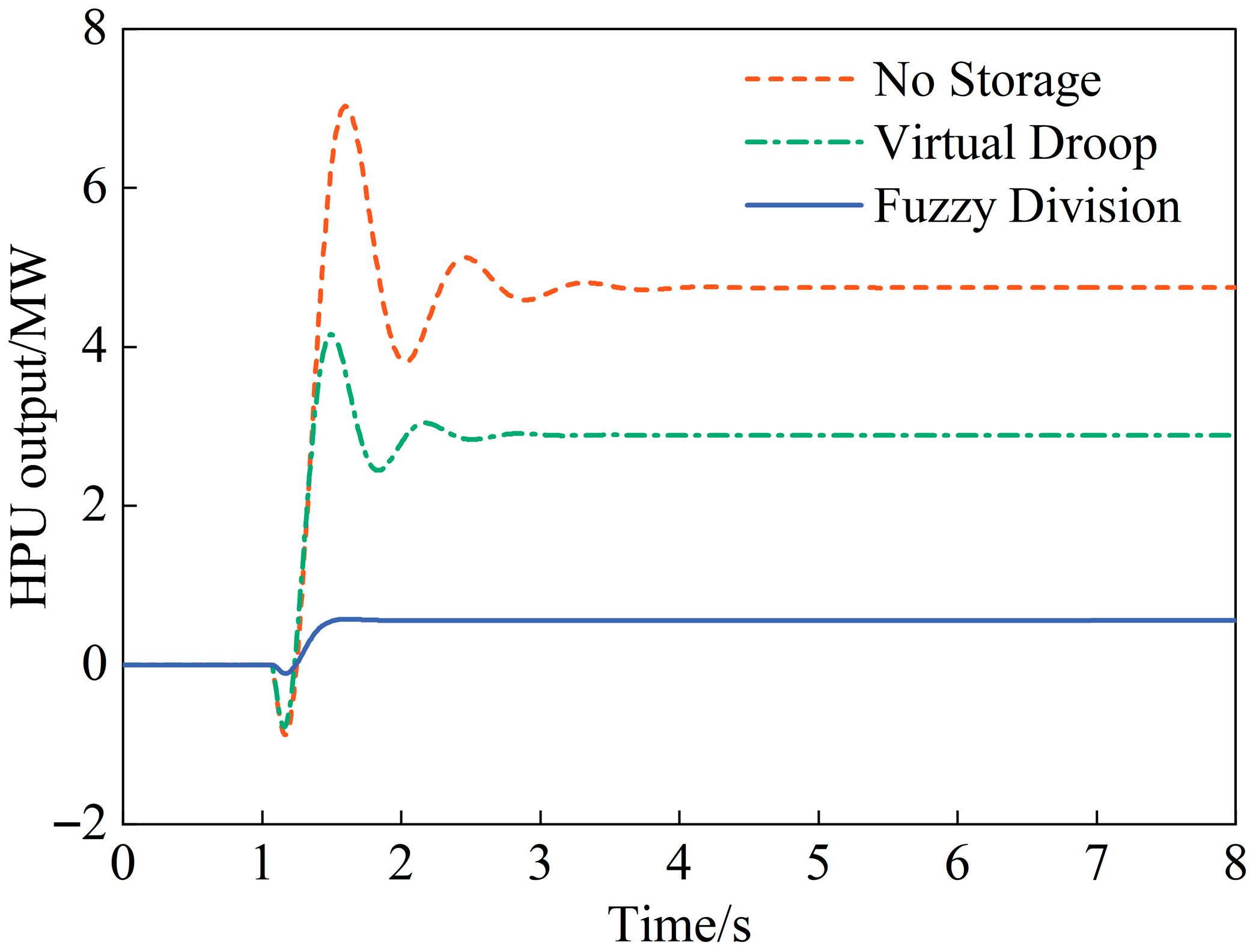
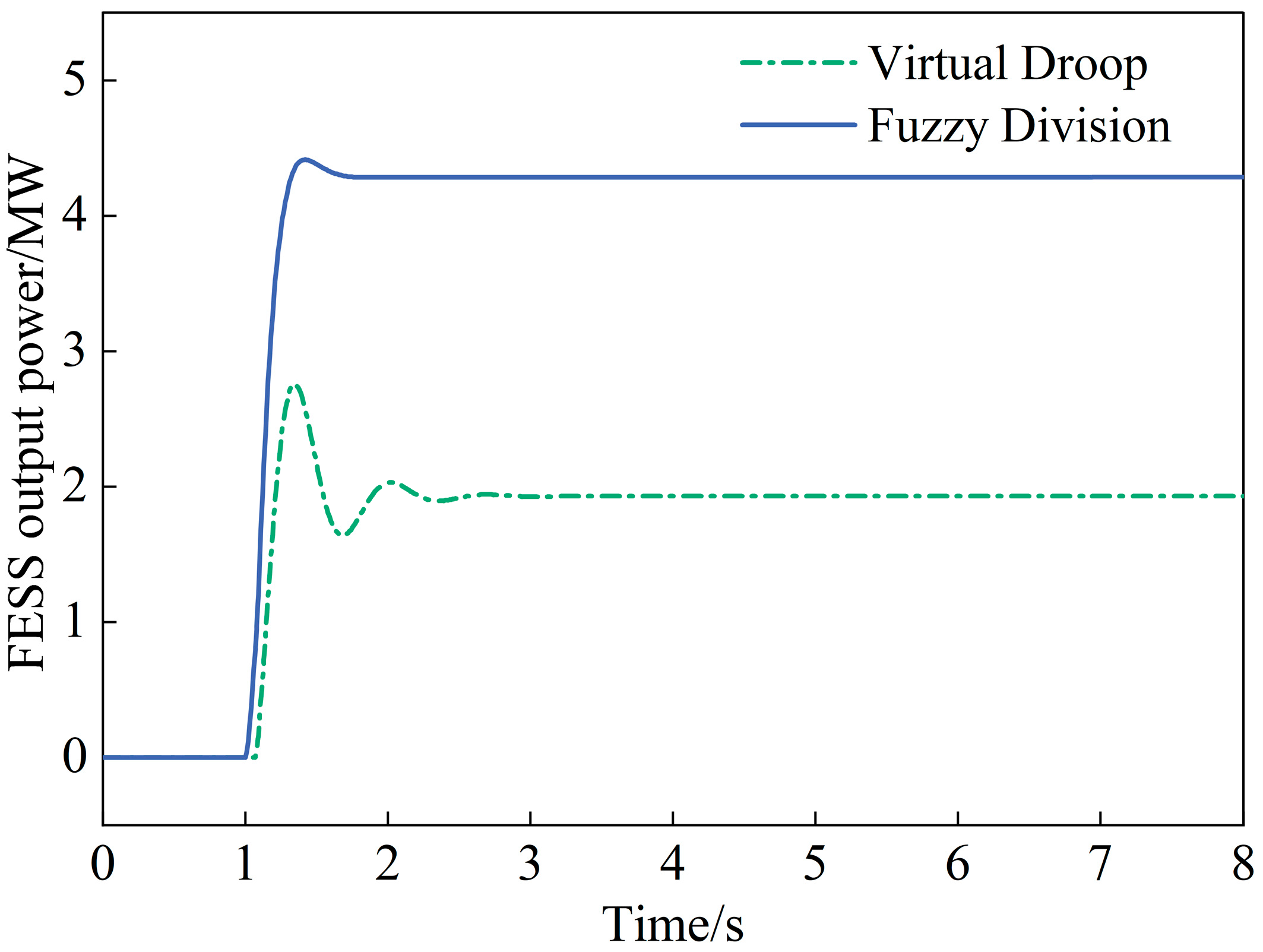
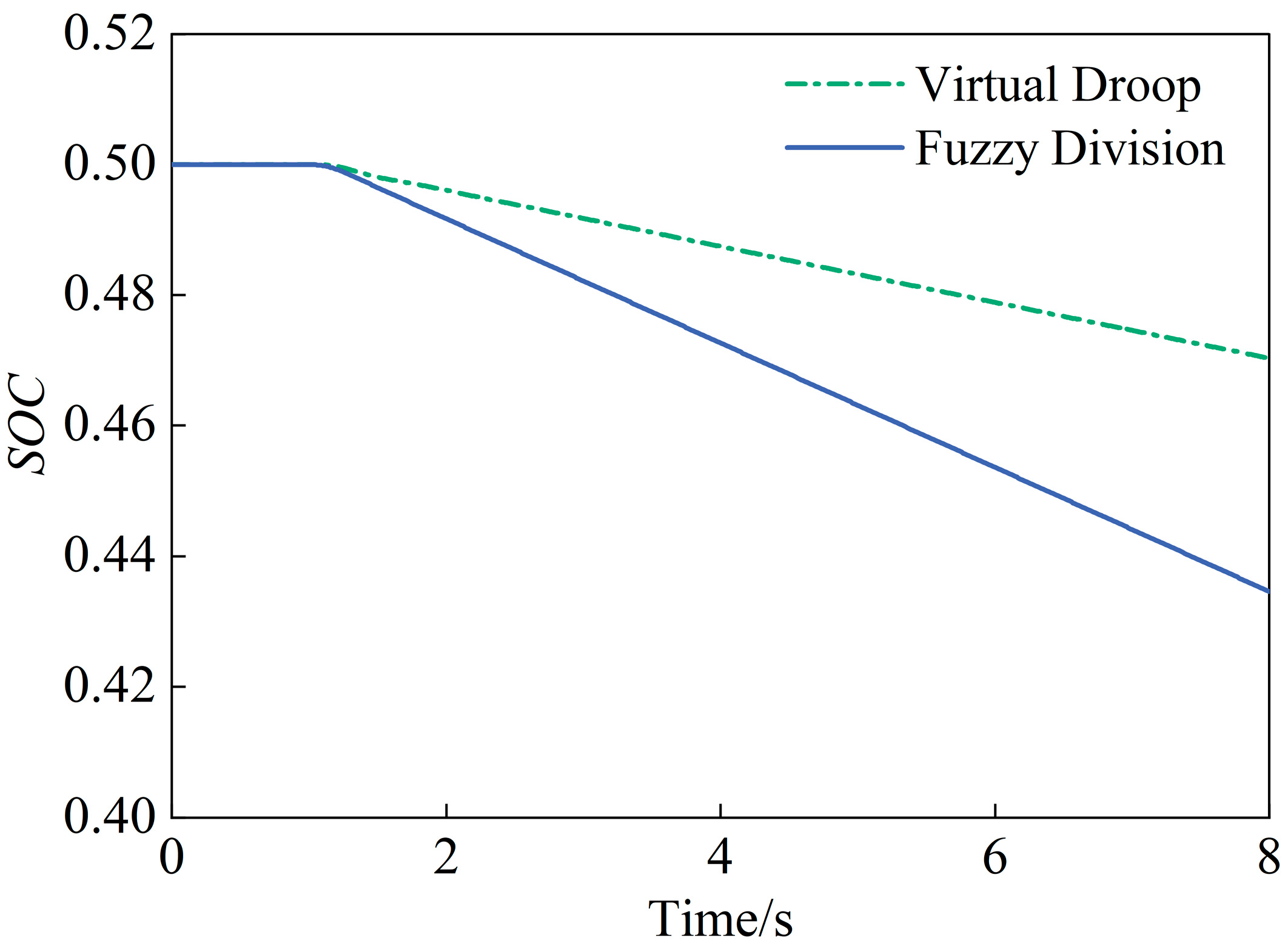
At t = 1 s, a 5 MW step load disturbance was applied, with the simulation duration set to 8 s. The system frequency values and output power of each unit under different control strategies are presented in Table 3. Figure 6, Figure 7, Figure 8 and Figure 9, respectively, show the frequency variation, HPU output power, flywheel output power, and S O C variation after the introduction of the step disturbance.
As shown in Figure 6, after FESS participates in the frequency regulation of HPU, it effectively prevents the frequency from experiencing an instantaneous significant drop. The virtual droop and fuzzy frequency division strategies raise the frequency nadir from 49.828 Hz (without energy storage) to 49.884 Hz and 49.920 Hz, respectively, reducing the maximum frequency deviation by 32.56% and 53.49% compared to the case without energy storage. Regarding steady-state frequency, both strategies improve the steady-state frequency from 49.872 Hz (without energy storage) to 49.909 Hz and 49.922 Hz, respectively, reducing the steady-state deviation by 28.91% and 39.06%. This demonstrates that the integration of FESS effectively enhances the frequency stability of the system when facing sudden load changes.
As can be seen from Figure 7, without energy storage participation, HPU reaches a peak power output of 7.023 MW and a steady-state value of 4.744 MW. After integrating FESS, FESS rapidly meets the instantaneous power demand due to its fast response and short-duration power supply capabilities. Under the conventional virtual droop control strategy, the peak power output of HPU is reduced by 40.89%, and its steady-state power output is reduced by 39.10%. With the fuzzy frequency division control strategy, the power output of HPU becomes smoother without a significant peak, and the steady-state power output is reduced by 88.24%, while effectively suppressing power reverse regulation in HPU. These results demonstrate that the incorporation of FESS significantly mitigates the power fluctuations caused by step disturbances in HPU.
As can be seen from Figure 8 and Figure 9, under the fuzzy frequency division strategy, FESS can respond to system frequency changes more rapidly by delivering substantial active power within a short period, thereby preventing overshoot in HPU. Compared with the virtual droop control strategy, the peak output power of FESS reaches 4.412 MW, representing an increase of 60.08%, while the steady-state output reaches 4.287 MW, showing an improvement of 122.23%. This demonstrates that the fuzzy frequency division strategy better leverages the advantages of FESS as a “power-type” energy storage system compared to the virtual droop strategy.

4.2. Continuous Disturbance

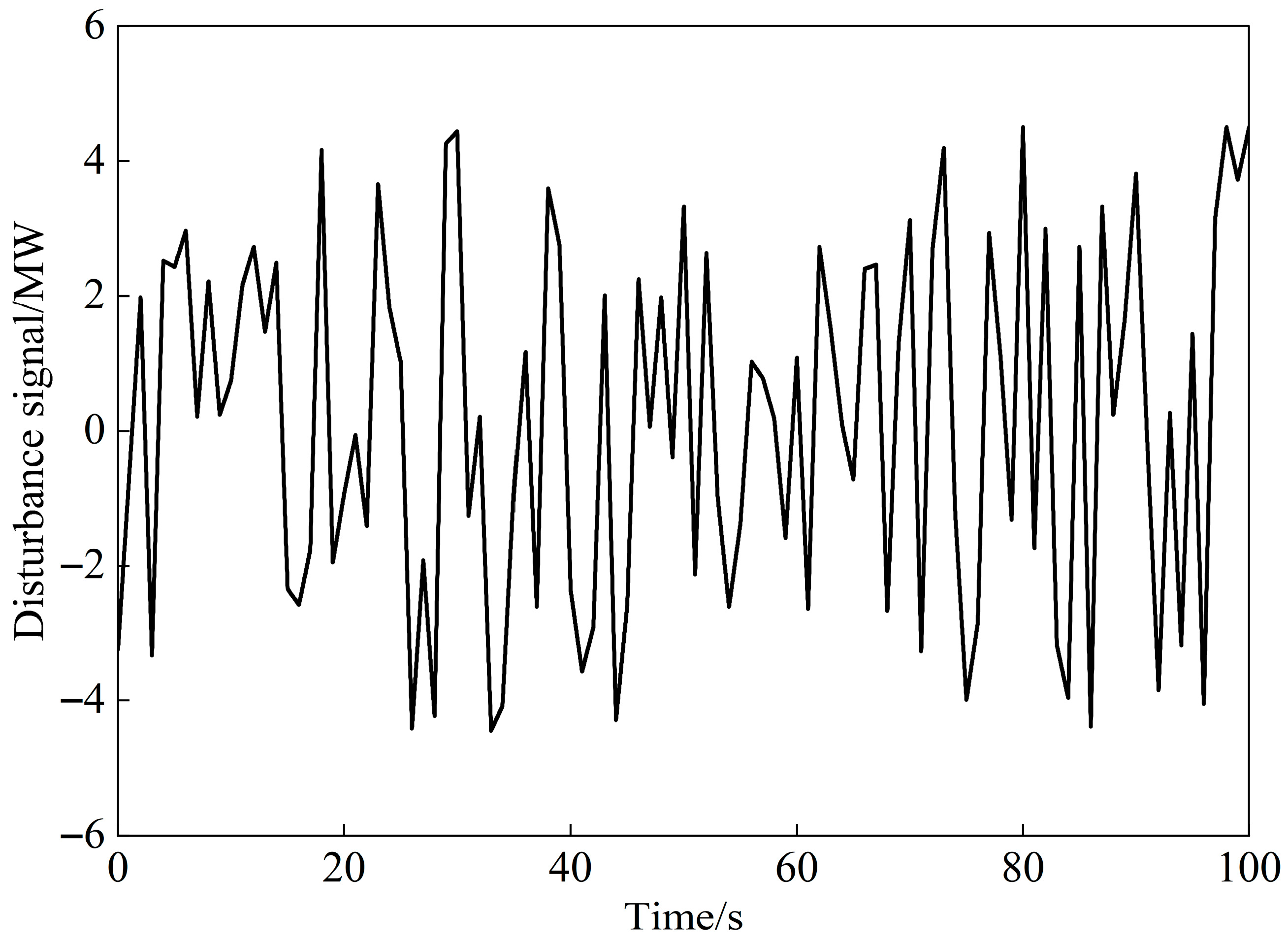
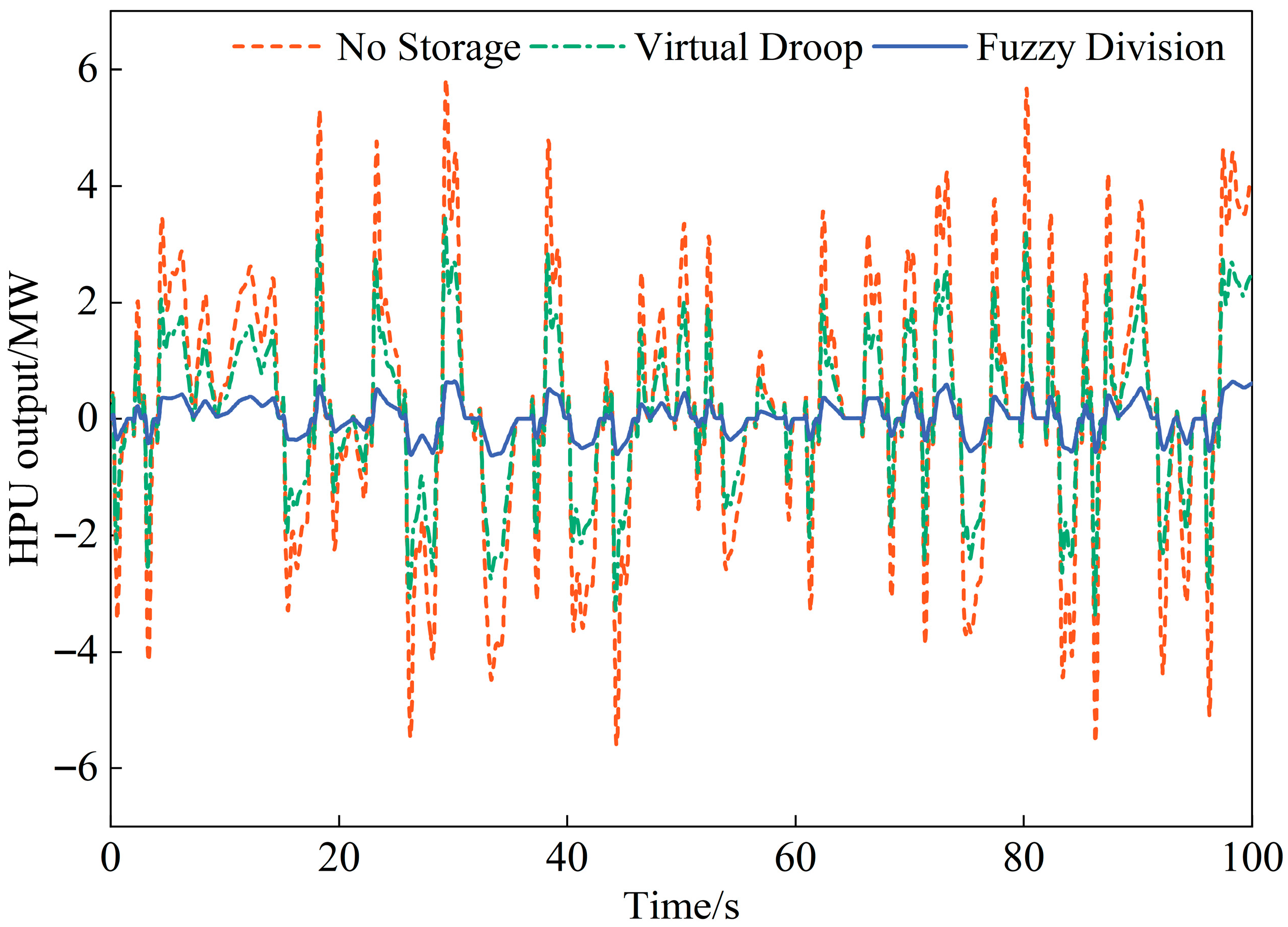
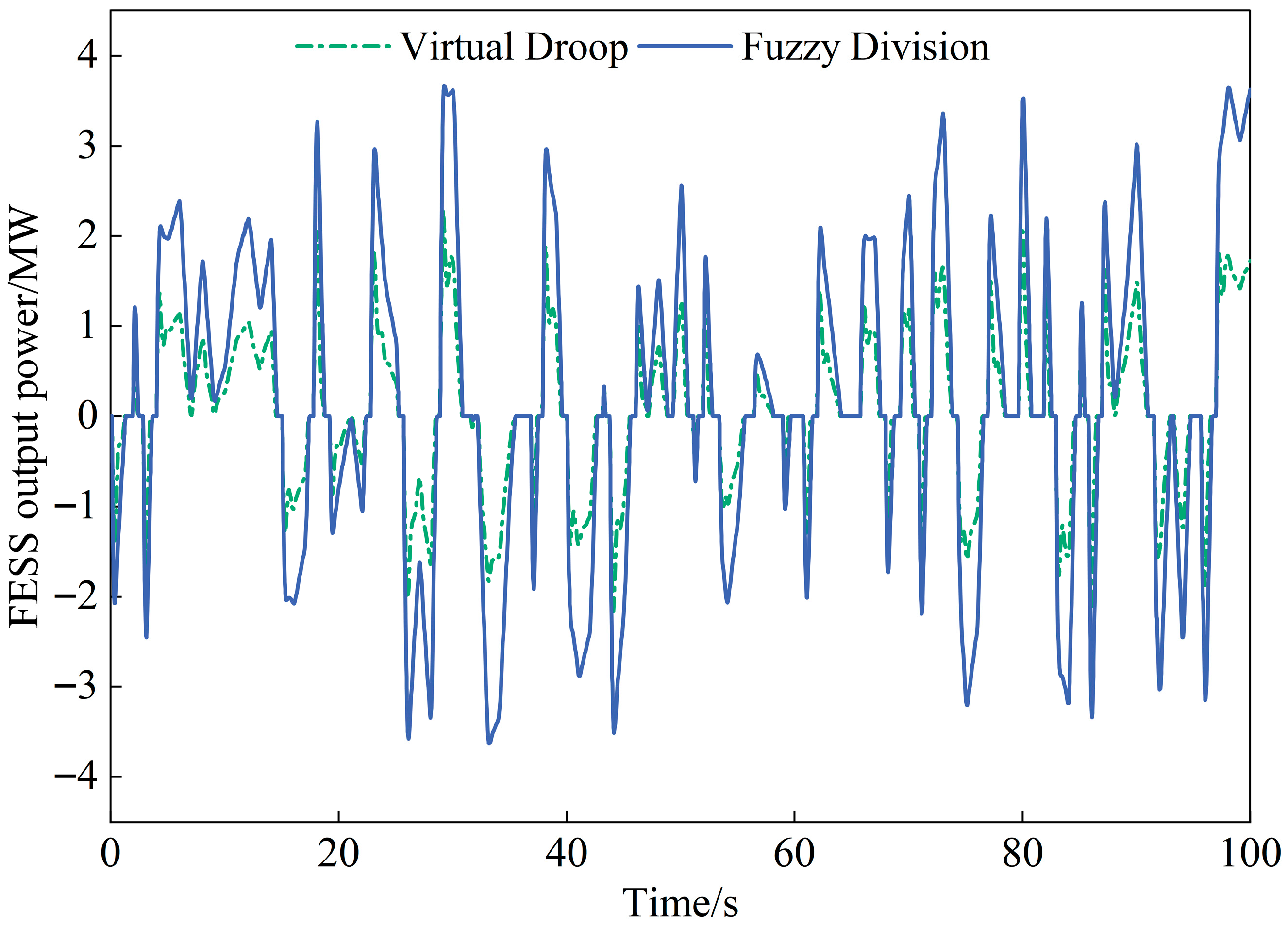
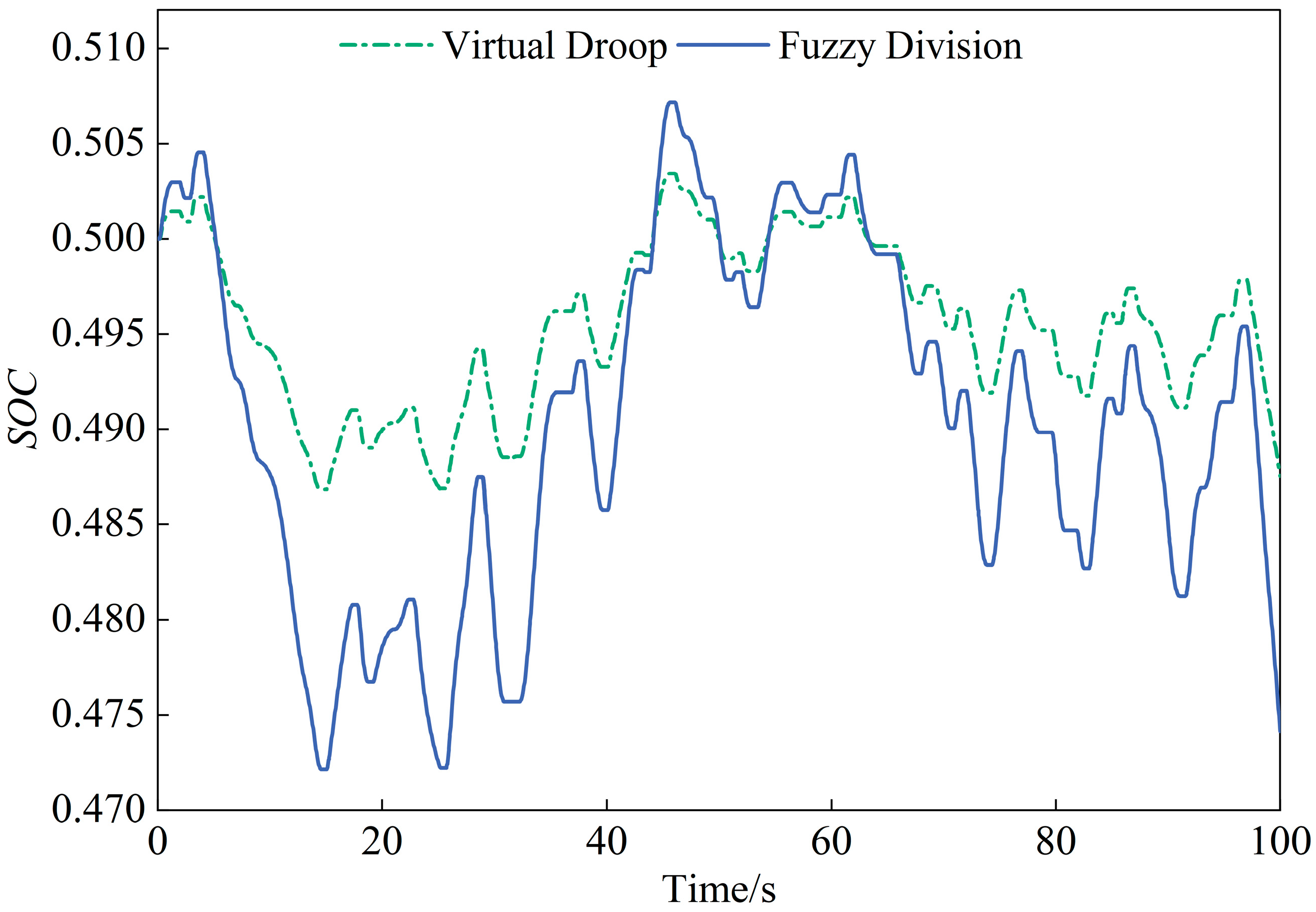
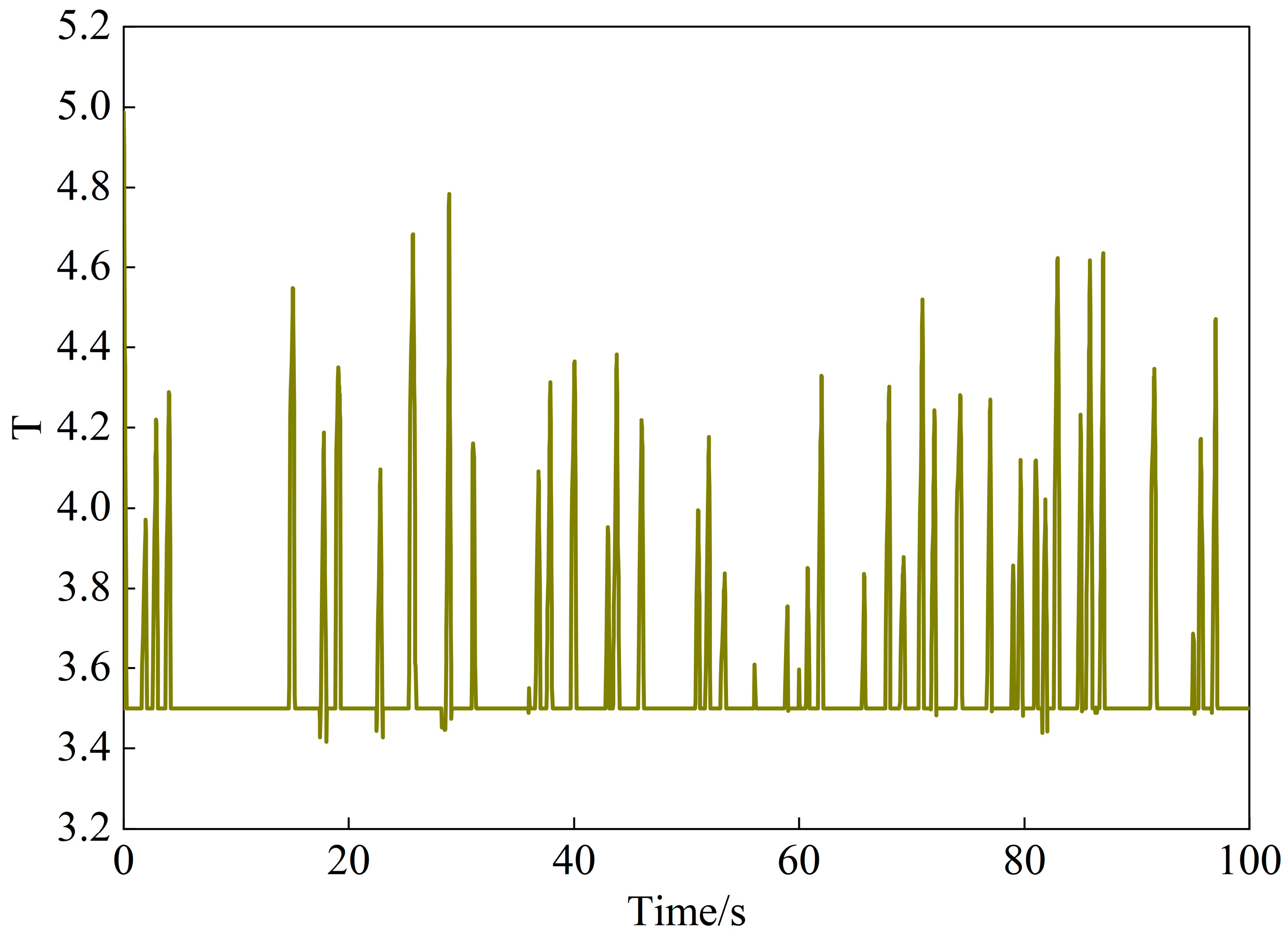
As previously discussed, FESS has been shown to effectively enhance the system’s frequency regulation capability and reduce power fluctuations in HPUs under step disturbances. However, continuous irregular small-amplitude load fluctuations are the primary cause triggering primary frequency regulation in power units. Therefore, it is necessary to investigate the effectiveness of the proposed strategies in improving hydroelectric frequency regulation under continuous disturbance conditions. A continuous disturbance signal with variations in the range of [−5, 5] MW was applied as the interference input, as shown in Figure 10, to compare and analyze the performance of the fuzzy frequency division strategy proposed in this paper under continuous operating conditions. The frequency regulation performance under different control strategies is summarized in Table 4. Figure 11, Figure 12, Figure 13, Figure 14 and Figure 15, respectively, illustrate the frequency variation, HPU output power, FESS output power, S O C and filter time constant variation curve under continuous disturbance.
As can be seen from Table 4 and Figure 11, under continuous disturbance conditions, the maximum frequency values for the no energy storage, virtual droop, and fuzzy frequency division control strategies are 50.144 Hz, 50.098 Hz, and 50.084 Hz, respectively, while the minimum frequency values are 49.852 Hz, 49.898 Hz, and 49.915 Hz, respectively. The RMSEs of frequency are 0.0621 Hz, 0.0484 Hz, and 0.0474 Hz, respectively. These results indicate that the integration of FESS demonstrates significant effectiveness in suppressing continuous fluctuations, with the proposed fuzzy frequency division strategy further reducing system frequency variations.
As shown in Figure 12, under continuous disturbance conditions, the power fluctuation ranges of HPUs under the three control strategies—no energy storage, virtual droop, and fuzzy frequency division—are 11.44 MW, 6.82 MW, and 1.28 MW, respectively, representing reductions of 40.38% and 88.81%. This indicates that integrating energy storage for frequency regulation can significantly reduce the output power fluctuation range of hydroelectric units. As illustrated in Figure 13, under the fuzzy frequency division strategy, the output power fluctuation range of FESS increases from 4.45 MW to 7.29 MW, a rise of 63.82%, further leveraging the advantages of FESS and enabling its active participation in frequency regulation tasks.
As shown in Figure 14 and Figure 15, the increased filter time constant T requires FESS to handle more high-frequency components of frequency regulation demands, demonstrating faster discharge output and charge recovery responses. This indicates that the fuzzy frequency division strategy can significantly smooth the output power of hydroelectric units, effectively avoiding large power fluctuations. By alleviating frequency regulation pressure, the strategy not only reduces mechanical wear on the equipment but also extends its service life and maintenance cycles, thereby enhancing the overall stability and economic efficiency of the system.
The aforementioned simulation analyses are all conducted based on a widely used generic model of a Francis turbine. For Kaplan or Pelton turbines, by updating their specific turbine-governor transfer functions to accurately capture their dynamic characteristics, the control structure and fuzzy logic rules remain valid and are expected to deliver similar performance enhancements.

5. Conclusions

This study establishes a model of a FESS assisting a HPU in PFR and proposes a novel fuzzy frequency division control strategy. Simulations under both step and continuous load disturbances validate the effectiveness of this coordinated approach. The key findings are:
(1)
Enhanced frequency regulation performance: The integration of the FESS significantly improves the system’s frequency response. Under a step disturbance, the proposed strategy reduces the maximum frequency deviation by 53.49% and improves the steady-state frequency by 39.06% compared to HPU-only operation, outperforming conventional virtual droop control. During continuous fluctuations, the strategy effectively suppresses frequency deviations and improves the HPU’s own regulatory performance.
(2)
Improved operational conditions for the HPU: The FESS mitigates mechanical stress on the HPU. The fuzzy frequency division control strategy leverages the flywheel’s rapid response to prevent sudden, large power changes in the HPU during step disturbances. Under continuous disturbances, the HPU’s output power fluctuations are significantly reduced, minimizing equipment wear. This enables the power plant to reliably provide more ancillary services, enhancing its economic value.
(3)
Optimized role of FESS: The proposed strategy fully utilizes the power-type characteristics of the FESS. It enables the flywheel to provide higher short-term power during initial stage of a step disturbance and undertake a larger share of the regulating burden during continuous fluctuations. This proactively meets PFR demands and effectively reduces the strain on the HPU.
In summary, the fuzzy frequency division control strategy demonstrates a substantial improvement in the frequency support capability provided by hydroelectric plants. While this study is simulation-based, it presents a promising control framework for grid regulation. Future work will focus on experimental validation and adapting the strategy for real-world, multi-source hybrid energy systems.

Author Contributions

Conceptualization, Z.L.; software, P.G., N.X., D.M., Q.M. and T.Z.; validation, P.G., N.X., D.M. and Q.M.; formal analysis, investigation, Z.L., J.L. and T.Z.; resources, H.Z.; data curation, Z.L. and P.G.; writing—original draft, D.M. and T.Z.; writing—review and editing, H.Z.; visualization, J.L. and Q.M.; funding acquisition, H.Z.; methodology, N.X. and J.L. All authors have read and agreed to the published version of the manuscript.

Funding

This research was funded by the [Natural Science Basic Research Program of Shaanxi] grant number [2021JQ-471] and Natural Science Special Project of Shaanxi Provincial Department of Education grant number [21JK0802].

Data Availability Statement

The original contributions presented in this study are included in the article. Further inquiries can be directed to the corresponding author.

Conflicts of Interest

Authors Zhengfa Li, Peina Gao and Ning Xu were employed by the company State Grid Gansu Electric Power Company Construction Branch. Author Jian Lu was employed by the company State Grid Gansu Electric Power Company Wuwei Power Supply Company. Author Miao Dong was employed by the company State Grid Gansu Electric Power Company Lanzhou Power Supply Company. Author Qiong Ma was employed by the company State Grid Gansu Electric Power Company Linxia Power Supply Company. The remaining authors declare that the research was conducted in the absence of any commercial or financial relationships that could be construed as a potential conflict of interest.

References

  1. Etanya, T.F.; Tsafack, P.; Ngwashi, D.K. Grid-Connected Distributed Renewable Energy Generation Systems: Power Quality Issues, and Mitigation Techniques—A Review. Energy Rep. 2025, 13, 3181–3203. [Google Scholar] [CrossRef]
  2. Zhou, D.; Pan, X.; Sun, X.; Hu, F. Resilience Assessment Framework for High-Penetration Renewable Energy Power System. Sustainability 2025, 17, 2058. [Google Scholar] [CrossRef]
  3. Sadeghian, O.; Shotorbani, A.M.; Ghassemzadeh, S.; Mohammadi-Ivatloo, B. Energy Management of Hybrid Fuel Cell and Renewable Energy Based Systems-A Review. Int. J. Hydrogen Energy 2025, 107, 135–163. [Google Scholar] [CrossRef]
  4. Gonzalez-Salazar, M.; Poganietz, W.R. Evaluating the Complementarity of Solar, Wind and Hydropower to Mitigate the Impact of El Nino Southern Oscillation in Latin America. Renew. Energy 2021, 174, 453–467. [Google Scholar] [CrossRef]
  5. Zhang, C.; Cao, W.; Xie, T.; Wang, C.; Shen, C.; Wen, X.; Mao, C. Operational Characteristics and Optimization of Hydro-PV Power Hybrid Electricity System. Renew. Energy 2022, 200, 601–613. [Google Scholar] [CrossRef]
  6. Zhao, X.; Ren, Y.; Sha, Y.; Zhang, L.; Hou, S.; Xiao, F.; Chen, F.; Chen, S.; He, K.; Luo, L.; et al. Research on the Impact of Hydro-PV Complementary System Operation on Power Grid Based on New Energy Consumption. Math. Probl. Eng. 2022, 2022, 8459948. [Google Scholar] [CrossRef]
  7. Liu, D.; Zhao, S.; Zhang, J. Adaptive PID Control of Hydropower Units Based on Particle Swarm Optimization and Fuzzy Inference. Water 2025, 17, 1512. [Google Scholar] [CrossRef]
  8. Dong, W.; Cao, Z.; Zhao, P.; Yang, Z.; Yuan, Y.; Zhao, Z.; Chen, D.; Wu, Y.; Xu, B.; Venkateshkumar, M. A Segmented Optimal PID Method to Consider Both Regulation Performance and Damping Characteristic of Hydroelectric Power System. Renew. Energy 2023, 207, 1–12. [Google Scholar] [CrossRef]
  9. Jia, Y.; Tan, B.; Zhang, W.; Jiang, D.; Yang, C.; Wen, Y. A Novel Control Strategy for Hydraulic Turbines to Consider Both Primary Frequency Regulation and Ultra-Low Frequency Oscillation Suppression. Energies 2024, 17, 1067. [Google Scholar] [CrossRef]
  10. Liu, Z.; Yan, Z.; Zhang, H.; Xie, H.; Zou, Y.; Zheng, Y.; Xiao, Z.; Chen, F. Suppression and Analysis of Low-Frequency Oscillation in Hydropower Unit Regulation Systems with Complex Water Diversion Systems. Energies 2024, 17, 4831. [Google Scholar] [CrossRef]
  11. Chen, G.; Tang, F.; Shi, H.; Yu, R.; Wang, G.; Ding, L.; Liu, B.; Lu, X. Optimization Strategy of Hydrogovernors for Eliminating Ultralow-Frequency Oscillations in Hydrodominant Power Systems. IEEE J. Emerg. Sel. Top. Power Electron. 2018, 6, 1086–1094. [Google Scholar] [CrossRef]
  12. Lu, X.; Li, C.; Liu, D.; Wang, H.; Zhu, Z.; Ta, X.; Xu, R. Correlating Analysis and Optimization between Hydropower System Parameters and Multi-Frequency Oscillation Characteristics. Energy 2024, 304, 131789. [Google Scholar] [CrossRef]
  13. Liao, Y.; Yang, W.; Wang, Z.; Huang, Y.; Chung, C.Y. Mechanism of Primary Frequency Regulation for Battery Hybridization in Hydropower Plant. CSEE J. Power Energy Syst. 2024, 10, 2127–2137. [Google Scholar] [CrossRef]
  14. Feng, C.; Mai, Z.; Wu, C.; Zheng, Y.; Zhang, N. Advantage of Battery Energy Storage Systems for Assisting Hydropower Units to Suppress the Frequency Fluctuations Caused by Wind Power Variations. J. Energy Storage 2024, 78, 109989. [Google Scholar] [CrossRef]
  15. Ojo, Y.; Alam, S.M.S.; Balliet, W.H.; Mosier, T.M. Frequency Response Improvement in a Standalone Small Hydropower Plant Using Battery Storage. IEEE Trans. Energy Convers. 2024, 39, 2701–2717. [Google Scholar] [CrossRef]
  16. Gerini, F.; Vagnoni, E.; Seydoux, M.; Cherkaoui, R.; Paolone, M. Enhanced Frequency Containment Reserve Provision from Battery Hybridized Hydropower Plants: Theory and Experimental Validation. Electr. Power Syst. Res. 2024, 235, 110765. [Google Scholar] [CrossRef]
  17. Shu, H.; He, Y.; Wang, G.; Zhang, H.; Shi, B.; Luo, S. Research on Water Hammer Effect and Cooperative Frequency Regulation Technology of PV-HBESS Compensated Hydroturbine. IEEE Trans. Sustain. Energy 2025, 16, 919–932. [Google Scholar] [CrossRef]
  18. Esparcia, E.A.; Castro, M.T.; Odulio, C.M.F.; Ocon, J.D. A Stochastic Techno-Economic Comparison of Generation-Integrated Long Duration Flywheel, Lithium-Ion Battery, and Lead-Acid Battery Energy Storage Technologies for Isolated Microgrid Applications. J. Energy Storage 2022, 52, 104681. [Google Scholar] [CrossRef]
  19. Dragoni, E. Mechanical Design of Flywheels for Energy Storage: A Review with State-of-the-Art Developments. Proc. Inst. Mech. Eng. Pt. L J. Mater. Des. Appl. 2019, 233, 995–1004. [Google Scholar] [CrossRef]
  20. Tziovani, L.; Hadjidemetriou, L.; Charalampous, C.; Tziakouri, M.; Timotheou, S.; Kyriakides, E. Energy Management and Control of a Flywheel Storage System for Peak Shaving Applications. IEEE Trans. Smart Grid 2021, 12, 4195–4207. [Google Scholar] [CrossRef]
  21. Cai, X.; Li, X.; He, X.; Yang, Z.; Peng, D.; Ao, C. Research and Simulation of Hydraulic Turbine Speed Control System Based on Fuzzy Control. Procedia Comput. Sci. 2024, 241, 397–402. [Google Scholar] [CrossRef]
  22. He, L.; Li, W. Research and simulation of hydraulic turbine speed control system based on fuzzy control. Energy Storage Sci. Technol. 2021, 10, 1679–1686. [Google Scholar] [CrossRef]
  23. Wen, S.; Gong, Y.; Zhao, Z.; Mu, X.; Zhao, S. Power Grid Primary Frequency Control Strategy Based on Fuzzy Adaptive and State-of-Charge Self-Recovery of Flywheel-Battery Hybrid Energy Storage System. Energies 2025, 18, 1536. [Google Scholar] [CrossRef]
  24. Qin, H.; Qin, L.; Bai, X.; Li, C. A control strategy of flywheel energy storage system participating frequency regulation with pumped storage. Energy Storage Sci. Technol. 2022, 11, 3915–3925. [Google Scholar] [CrossRef]
  25. Lu, E.; Chen, L.; Li, J.; Yao, L.; Zheng, B.; Mo, B. Research on power system frequency regulation based on improved fuzzy control. Power Syst. Prot. Control. 2017, 45, 46–52. [Google Scholar] [CrossRef]
Figure 1. PFR for generating units.
Energies 18 06032 g001
Figure 2. Diagram of FESS.
Energies 18 06032 g002
Figure 3. Logistic function simulating battery charging/discharging diagram.
Energies 18 06032 g003
Figure 4. Control strategy for FESS assisting PFR in HPU.
Energies 18 06032 g004
Figure 5. Membership functions of input and output variables. (a) Membership Function of d ( Δ f ) / d t ; (b) Membership Function of S O C ; (c) Membership Function of T .
Energies 18 06032 g005
Figure 6. Step disturbance response curve of system frequency.
Energies 18 06032 g006
Figure 7. Step disturbance response curve of HPU output power.
Energies 18 06032 g007
Figure 8. Step disturbance response curve of FESS output power.
Energies 18 06032 g008
Figure 9. Step disturbance response curve of S O C .
Energies 18 06032 g009
Figure 10. Continuous disturbance signal.
Energies 18 06032 g010
Figure 11. Continuous disturbance response curve of system frequency.
Energies 18 06032 g011
Figure 12. Continuous disturbance response curve of HPU output power.
Energies 18 06032 g012
Figure 13. Continuous disturbance response curve of FESS output power.
Energies 18 06032 g013
Figure 14. Continuous disturbance SOC.
Energies 18 06032 g014
Figure 15. Filter time constant variation.
Energies 18 06032 g015
Table 1. Control rules.
d ( Δ f ) / d t S O C
NBNSZEPSPB
NBNBNMPSPMPB
NSNBNSPZPSPM
NZNMNSNZPZPS
PZPSPZNZNSNM
PSPMPSPZNSNB
PBPBPMPSNMNB
Table 2. Simulation parameters.
ParameterValueParameterValue
δ 0.04 D 1
T g 0.05 K F 16.7
T w 0.1 T F 0.02
H 5 S O C 0 0.5
Table 3. System frequency values of different control strategies and output values of each unit.
Control StrategiesNadir
Frequency/Hz
Steady-State
Frequency/Hz
HPUFESS
Peak Power
Output/MW
Steady-State Value/MWPeak Power
Output/MW
Steady-State Value/MW
No Storage49.82849.8727.0234.744//
Virtual Droop49.88449.9094.1512.8892.7561.929
Fuzzy Division49.92049.922/0.5584.4124.287
Table 4. Frequency variation under different control strategies.
Control StrategiesFrequency Nadir/HzFrequency Peak/HzRMSE/Hz
No Storage49.85250.1440.0621
Virtual Droop49.89850.0980.0484
Fuzzy Division49.91550.0840.0474
Disclaimer/Publisher’s Note: The statements, opinions and data contained in all publications are solely those of the individual author(s) and contributor(s) and not of MDPI and/or the editor(s). MDPI and/or the editor(s) disclaim responsibility for any injury to people or property resulting from any ideas, methods, instructions or products referred to in the content.