Article

Potential Properties and Applications of Wires with Helical Structure in High-Voltage Overhead Power Lines and PV Systems

by
Adam Steckiewicz
1,*,
Maciej Zajkowski
1 and
Andrijana Jovanovic
2
1
Department of Electrical Engineering, Bialystok University of Technology, Wiejska 45D Str., 15-351 Białystok, Poland
2
Department of Electrical Power Engineering, Faculty of Technical Sciences, University of Priština in Kosovska Mitrovica, RS-38220 Kosovska Mitrovica, Serbia
*
Author to whom correspondence should be addressed.
Energies 2025, 18(22), 6008; https://doi.org/10.3390/en18226008 (registering DOI)
Submission received: 12 October 2025 / Revised: 13 November 2025 / Accepted: 14 November 2025 / Published: 16 November 2025
(This article belongs to the Special Issue Advances in Solar Systems and Energy Efficiency: 2nd Edition)

Abstract

High-voltage overhead power lines consist of the non-insulated, densely packed round or trapezoidal aluminum strands supported by a reinforced core. This configuration may ensure the acceptable investment cost, mass per unit length, and aerodynamic effects caused by wind; however, the ampacity is lower than those of copper wires, which limits the power transmission. Today, it is especially important, since the peak power generation of, e.g., photovoltaics forces power lines to casually distribute high currents. To potentially improve long- and short-term capabilities of energy distribution, instead of a cylindrical wire, the helical structure was proposed. Preserving an identical core, the conductor was formed as many elongated helices wrapped around an aluminum tube. The design was meant to significantly enlarge the outer surface of the wire, improving the heat transfer of the line, which then allowed us to enhance its ampacity. The solution was investigated numerically utilizing a 3D model with the coupled electrical, heat transfer, and laminar flow analysis. Based on this, the parameters (unit weight, unit resistance, and aerodynamic drag) of such modified wires were identified. Then, at different current loadings and wind speeds, the conductors were studied and compared with the ACSS (aluminum conductor steel-supported). The optimal variants of helical wires were suggested and the results indicated that using the helical conductor makes it possible to increase the ampacity of power lines (with the same unit weight, resistance, and cross-section of the ACSS wire) by 44% at low wind speed, even up to 160% at higher temperatures.

1. Introduction

Long-distance energy transfer relies mostly on high-voltage and ultra-high-voltage systems [1,2,3,4]. Among many disadvantages, such as constantly visible power poles with their equipment (negatively affecting a landscape) [5,6,7], the risk of an extremely dangerous electric shock (during failures), and an exposure to weather conditions [8,9,10], the benefits of their usage are continuously prevailing. Investment and maintenance costs are lower than underground cable grids [11,12,13], less effort needs to be put into excavation work, and non-insulated wires (lighter and cheaper) can be utilized [14,15,16]. Overhead lines are likely to dominate as the main solution of transmitting the highest powers over the longest distances for decades. It became more important in the context of modern societies committed to a sustainable development [17], where not only renewable energy sources continuously increase their interest and the amount of operating power [18,19]. In addition, a growing demand for an electric energy supply is observed [20,21,22,23] with an accompanied increase in, e.g., electric vehicles and electrically powered heat sources [24,25,26,27]. Thus, the entire electric supply system must keep pace with the rising powers produced in distributed networks (equipped with green sources) and consumed by many novel receivers, including those casually requiring high powers. The ability to periodically transmit them could be substantially important in future. For example, the capacity of photovoltaic systems may grow, leading to an issue with the large amount of energy (generated between late sunrise and early sunset) which needs to be expended, thereby causing an imminent, temporary overload of the transmission network [22,23].
However, if more energy must be transferred at any distance, the existing grids must be expanded or upgraded. Building new lines entails the highest costs [28]; however, modernization can also be visibly expensive if extensive power poles are needed [29] to cope with the greater mechanical load imposed by extra and/or larger conductors. One of the solutions, limiting the effort needed to be put into the modernization, may be a simple replacement of the present wires (and their mounting hardware) with new overhead conductors, having broadly the same unit weight but higher ampacity. Today, one of the most widespread choices are ACSR (aluminum conductor steel reinforced) cables [30], consisting of many round aluminum wires, enclosing steel strands that take a part of a mechanical tension. Although this solution has advantages in terms of reduced costs and worldwide availability, the maximum operating temperature is around 70 to 100 °C [31,32,33,34], which limits its current-carrying capacity. Additionally, the ACSR are only structurally reinforced by the steel rods, meaning that construction also depends on the tensile strength of the aluminum layers. In a similar solution of ACSS (aluminum conductor steel-supported) wire, a soft, annealed aluminum is used, which provides the ability of self-damping mechanical vibrations and may withstand temperatures up to 150 °C [35], since more tension will be passed on the steel core, reducing thermal expansion and sag. There are also known modifications of ACSR and ACSS with trapezoidal wire (TW), meaning that aluminum wires have a trapezoidal cross-section [36]—this helps to utilize the empty space inside the wire (occurring between round wires), leading to reduction in the unit resistance. To dispose of the problems caused by the presence of steel (higher weight, hysteresis losses, and an electrical conductivity lower than aluminum), a group of conductors made solely of aluminum wires were developed, i.e., AAC (all-aluminum conductor) [37], AAAC (all-aluminum alloy conductor) [38], and ACAR (aluminum conductor alloy reinforced) [39]. They eliminate negative effects of steel but, on the other hand, they can be found mostly in short-distance and lower-power overhead lines where mechanical load, temperatures (causing elongation and sag) resulting from carried current, as well as weather and environment influences are less restrictive than in ACSR/ACSS lines [40,41]; hence, they will not be able to replace them in order to increase overall ampacity. The other approach was made in many HTLS (high-temperature low-sag) conductors, by substituting an aluminum/iron core with the composite (carbon and glass fibers) [42]. In such an ACCC (aluminum conductor composite core), ACCR (aluminum conductor composite reinforced), and ACFR (aluminum conductor fiber reinforced), wires were reported with not only the lower sag and elongation, but also with an ability to operate with temperatures up to 250 °C [43] and, at this temperature, carry nearly double the current as in previous types of aluminum conductors [44]. However, the last two properties appear to be idealized—some documents show [45] that such extreme temperatures will not be practiced, while this will allow for the increase of ampacity slightly, leaving the high current values only for emergency, and temporary overloads of power distribution lines. As an uncommon alternative, hollow conductors [46] in the form of a tube with greater diameter can be considered. Despite minimizing the partial discharge effects [47], it seems to be a good candidate to potentially replace other overhead wires, since (by having larger outer surface) the structure will provide better heat exchange. This implies that for the same cross-section of the conducting area as the preceding wires, the tubular conductor may ensure the increase in current loading at identical maximum operating temperature. Still, the tubular geometry without adjoined steel or composite core produces significant problems in mounting and tensioning, while a larger area for convective heating must not be sufficient to ensure expected ampacity.
In this article, an alternative remedy to the abovementioned issues has been considered. To improve the power transmission capabilities of both new and existing overhead, high-voltage power lines, the non-insulated wires with a helical shape, were introduced. An annealed aluminum conductor was used and supported with steel strands, identical as in ACSS wire, to preserve the application of the well-established concept including materials, gravitational load, potential to operate in the weather conditions as in the classic approach, and even (partially) an installation. The introduced design utilized steel strands placed inside a thin aluminum tube, on which several aluminum helices were attached and wrapped at a specific pitch. The examination was based on the three-dimensional (3D) numerical simulations and theoretical analysis. The numerical model of these modified wires had been prepared with a conjugate solution of electric, heat transfer, and laminar flow phenomena. The model allows the thickness, number of helices, and their pitch to be adjusted, in order to achieve a structure possessing, e.g., the same conductors, their cross-section areas, unit resistance, and weight as an equivalent ACSR/ACSS wire. However, due to forming the conductor in a presented way, its outer surface increases substantially, which improves the rate of the convective heat transfer. Therefore, for the specific nominal current, the mean temperature of a conductor can be reduced or for some imposed maximum operating temperature allowed in the overhead power line, the ampacity may increase. The benefits of better passive cooling performance were examined particularly for a different number of helices, wind speed, conducted current, and considering environmental conditions, such as solar radiation and ambient temperature. This helped to assess the performance and usefulness of some chosen variants. These variants were first found based on initial selection, where three basic parameters (unit resistance, unit weight, and unit drag force caused by wind) were compared and a deeper analysis of the best cases was made.

2. Materials and Methods

2.1. Analyzed Structure

The overhead conductor consists of several aluminum wires (round or trapezoidal) combined to form a cylindrical shape with an outer radius ra, and the inner steel strands of a radius rs provide mechanical support. The advantages of this structure, such as the ACSS/TW conductor shown in Figure 1, are a relatively easy assembly, compact shape, and a minimal diameter. On the contrary, a minimal outer surface of the entire wire is a disadvantage negatively affecting a heat exchange efficiency—according to Newton’s law of cooling, less surface means less heat dissipation, causing high temperature at a specific power loss. To enhance passive cooling capability of the overhead line, the external area should be extended. The easiest method would be to increase the diameter of the wire which, in fact, leads to a hollow type of conductor having an outer radius ro and an inner resection of a radius ri. However, the external surface is only proportional to ro and cannot be excessively elevated to avoid too-thin walls and, for large cross-sections of the conductor, the resulting tube may become unacceptably wide and susceptible to wind force.
Some combinations of the standard approach and the widening of the conductor can be a helical structure, presented at the center in Figure 1. Despite a larger axial size and the utilization of an inner tube with a wall thickness dr and steel strands inside, the outer area may be significantly increased due to the usage of ribbons (helices) with a width (wr) and a height (br) dependent on an imposed cross-section Aa, so that
b r = A a π d r 2 + 2 d r r s n w r ,
where n is the number of helices. The height of the ribbon (br) and the resulting size of the wire grow with the cross-section (Aa), though it can be reduced by increasing the number of ribbons (n) or thickening (wr) the helix.
The proposed solution uses steel support identical to ACxx types of wires and aluminum as the main conducting material; thus, it could be abbreviated as ACSS/nHW (aluminum conductor steel-supported n-helices wire). The conductor is formed as the n-ribbon structure made of annealed aluminum, which acts as a heat sink with helical ribs conducting the electric current. The heating losses generating in these ribs can then be passively dissipated in the air. The frontal area in Figure 1 also suggests a method of combing helices anchored to a section of an inner tube. It is anticipated that ACSS/nHW will replace any ACSS/ACSR (or even AAC, AAAC, and ACFR) conductor with the same support and cross-section (Aa), though the unit mass and resistance should be maintained at least the same, to not strain the existing equipment, mechanical load and power loss. In addition, the width (wr) of the helix and inner tube (dr) cannot be too small to avoid cracking, bending, or other damage appearing in the real-life long-term operation of a power line in different environmental conditions.
It should be stated that proposed conductors are intended for use in the high-voltage grids (60 kV to 220 kV) with 110 kV as a target nominal voltage. While applications in medium-voltage could be possible, the requirements regarding cross-sections of wires in such grids are lower, while smaller cross-sections would result in reduced size of the helices, leading to disappearance of the enhanced convective heat exchange. One may also note that ribs are elongated structures. This may lead to two issues, which must be verified during further, practical tests: firstly, the corona effect may not be reduced yet affected negatively due to the thin tips of ribbons; secondly, the spacing between them suggests the possibility of accumulating ice to a greater extent than in the case of a round conductor.
The larger external surface depends on adjustable parameters (n, a, wr, and dr) and is expected to cause an increase in ampacity, which was examined in further chapters, while not exceeding the maximum permissible temperature. This outer area of ACSS/nHW will be enlarged due to the usage of n helices (each having two sides) and, for a length equal to the height of a single revolution, the area of all helicoids can be expressed by the formula [48]:
S r = 2 n π b r b r 2 + a 2 4 π 2 + a 2 4 π 2 ln 2 π a b r + 2 π a b r 2 + a 2 4 π 2
where a—pitch of the helix, in m. According to Equations (1) and (2) and Figure 2, the effect of enhancing the external area strongly depends on the cross-section (Aa), and partially on the pitch and number of helices. For a relatively small cross-section (e.g., Aa = 120 mm2, Figure 2a), the outer surface (Sr) would be at least 60% larger than the surface of a round conductor (Sc), which is not a desirably high value. Nevertheless, it could be improved for the bigger cross-sections (e.g., Aa = 240 mm2, Figure 2b) where Sr can reach more than 280% of Sc; therefore, with larger cross-sections, the increase in the outer surface is also more significant. Such extension of the external area of the wire may unprecedentedly improve passive cooling efficiency of the structure. Although, the usage of many helices is not recommended, since above n ≈ 12, the relative outer surface (Sr/Sc) remains similar, tending asymptotically to a fixed value. Some gain of outer surface may arise from wrapping helices closely, forasmuch as small pitches (a << 1 m) results in the highest Sr/Sc.
It is practically important that the ribbon is twisted 360° along the pitch, making the conductor symmetrical regardless of the wind direction and the solar radiance. This should also prevent the wire from accumulating rainwater, dust, soot, and dirtiness, since twisted ribs will lead sludges to slip down thanks to the exposure to wind and gravity.

2.2. Numerical Model and Properties

The main goal is to increase the ampacity of conductors in an overhead line, and this is why the amount of radiated heat must be enhanced. To estimate a passive cooling efficiency, the problem must be then investigated by taking into account power loss reliant, for instance, on a resistivity of aluminum (ρa) at a temperature (T), e.g., assuming a linear model [49]:
ρ a = ρ 0 , a 1 + α a T T 0 ,
where T0—reference temperature, in K; αa—temperature coefficient of resistance, in 1/K; and ρ0,a—resistivity in reference temperature, in Ω·m. Equation (3) is also valid for calculating a resistivity of the steel strand (ρs), which will also conduct some part of a current:
ρ s = ρ 0 , s 1 + α s T T 0 ,
where αs, ρ0,a—temperature coefficient of resistance and the resistivity of steel in the reference temperature, respectively. Since resistivities are temperature-dependent, the coupled analysis of electric and thermal field was required.
Accordingly, let us assume a low-frequency, quasi-static electric [50] and magnetic field [51], which can be characterized by differential equations:
2 A j ω μ ρ T A = 0
J = 0 ,
J = 1 ρ T V + j ω A ,
where ∇—Nabla operator; A—magnetic vector potential, in Wb/m; ω—angular frequency, in rad/s; μ—magnetic permeability, in H/m; j—imaginary unit; J—current density vector, in A/m2; and V—spatial distribution of the electric potential, in V. It must be solved with the stationary Poisson’s equation [52], comprised of the distributed heat sources (q), in W/m3:
q = ρ T J 2 ,
which helps us to find the unknown temperature distribution by solving
λ T = q + g C p u T Q ,
where λ—thermal conductivity, in W/m·K; g—density, in kg/m3; Cp—heat capacity at constant pressure, in J/kg·K; Q—external heat source, in W/m3; and u—fluid velocity vector, in m/s. Equation (9) expands the analysis to combining the energy transport by fluids (in this particular case, the air) with variable velocity vector u. Continuously having the stationary field and considering a low Reynold’s number, the laminar flow can be modeled using the Navier–Stokes momentum equation with an inertial term [53], expressed in a form
g u T u = p I + ν u + u Tr 2 3 ν u I ,
where p—the pressure, in Pa; ν—dynamic viscosity, in Pa·s; I—the identity tensor; and Tr—transposition. To find the temperature distribution, resulting from electric heat source and heat transfer forced by wind with a specific velocity, Equations (3)–(10) must be taken into account simultaneously.
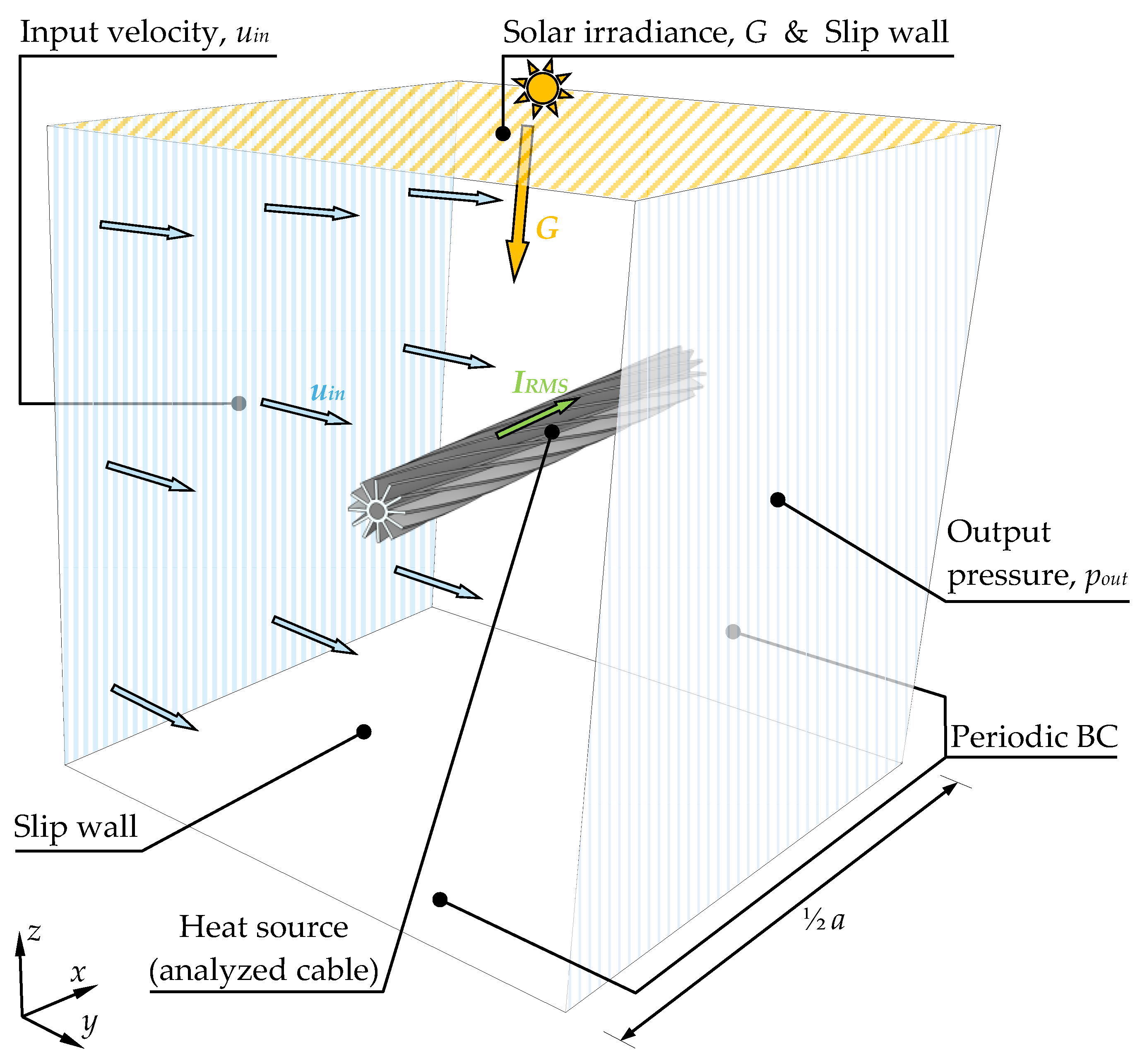
To estimate the effectiveness of the ACSS/nHW conductor, the 3D model had been prepared (Figure 3) and numerical examination was made. The electric field was calculated in the volume occupied by the conductor. Yet, instead of the power loss, the heat source had been imposed similarly as in Equation (8), by extorting the root mean squared value of current (IRMS) at the input area (s) of the wire at x = 0 as
I R M S = s J x = 0 2 d s ,
and a reference potential (V = 0) was allocated at x = ½a. Equation (11) and grounding the end of the wire served as the electric boundary conditions (BC), giving the ability to find the electric potential (V) distribution. The velocity and pressure field of moving gas was considered in the remaining volume of a cuboid. The wind was excited perpendicularly to the length of a wire—for this reason, a velocity vector u = [0 uin 0] at the left surface served as an input, and the surface on the right side, with a constant pressure pout = 0, acted as an output for the flowing air. The height (along z-axis) and depth (along y-axis) of the cuboid were equal to forty times the radius of a circle with an area of a cross-section Aa. Since helical structures possessed pitch (a), the width of the model (along x-axis) was changed accordingly, but due to the repetitive shape of the helicoid, only half of the pitch can be examined. Still, the intersections (front and back surfaces) should mimic the infinitely long wire; thus, the periodic BC were assumed and complemented by slip wall boundary conditions at upper and lower surfaces. Temperature (T) of the wire and air were found by calculating the thermal field in the entire model, assuming an initial ambient temperature (Tamb). In a bid to approach close to the real conditions, both radiation heating and cooling were simulated through a solar irradiance (G) on the upper surface and an emissivity (ε) on the external surfaces of wires.
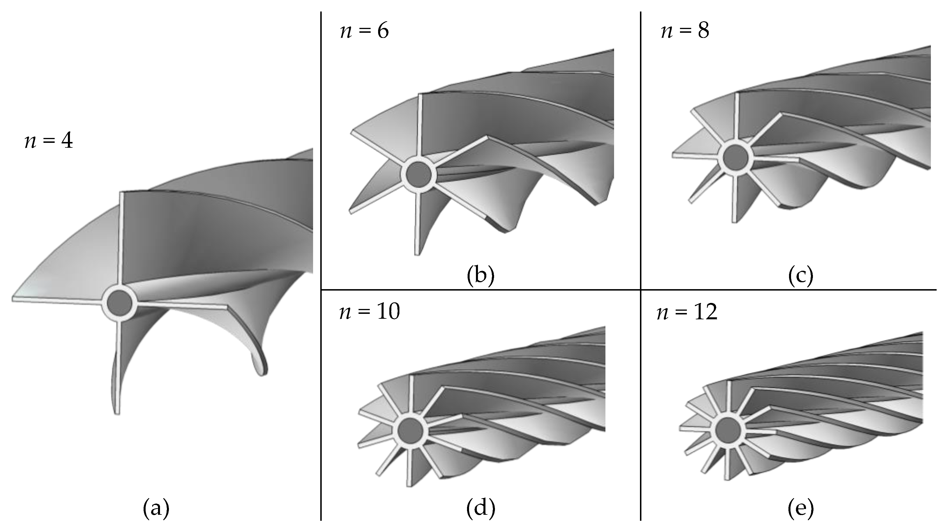
In the numerical model, where the pitch, wind speed, and current can be modified, the five main geometries of ACSS/nHW wires were examined (Figure 4). To simplify the analysis, an iron support, with an actual cross-section As of the steel parts, had been homogenized to a rod, having an effective resistivity:
ρ 0 , s = ρ 0 , s π r s 2 A s .
Since n can be changed, the starting geometry was made of n = 4 helices and the last structure had n = 12. While it is possible to make the wire with 1, 2, or 3 helices, these cases were not computed due to the resulting outer size—it can be easily observed that with lower n, the outer diameter visibly increases, causing potential problems with wind exposure as well as transport and installation. These issues may then be reduced by increasing the number of helices, but the large n would start familiarizing helical structure to the classic round wire, limiting the airflow through helicoids and then cooling efficiency.
In addition to the mean temperature of the wire, three more properties were evaluated. The unit weight (mu) in kg/km helps to estimate the load and the amount of the used metal. It was found by calculating the triple integral of density (g) in the space (v) occupied by aluminum and steel parts, divided by the length of conductor (½a) in kilometers. As it will be shown in Section 3, it strongly depends on the pitch (a) and number of helices (n). Then, the unit resistance (Ru), in Ω/km, was estimated by exciting the current IRMS = 1 A, giving the temperature of wire nearly equal to the ambient temperature (TTamb), thereby
R u = 1 I R M S 2 2 a v ρ T J 2 d v Power loss divided by length .
The simulation model with analysis of the electric field had the ability to estimate power loss per kilometer of the length and the resistance was found based on Joule’s first law.

3. Results and Discussion

3.1. Calculation Setup and Parameters

Three-dimensional analysis was performed in Comsol Multiphysics 4.3b software with the conjugate electric currents, heat transfer, and laminar flow modules. The model presented in Figure 3 had been complemented by parameters characterizing the environmental and material properties (Table 1). The high-voltage overhead lines usually require large cross-sections to transfer a high power with a minimal loss; therefore, frequently encountered Aa = 240 mm2 had been chosen for the preliminary examinations. Due to normalization [54] and practical approaches [55], the ACSS/TW wire (which serves as a reference to compare with ACSS/nHW) of such cross-sections should have the outer radius of approximately rc = 9.64 mm, the cross-section (As) and radius (rs) of the steel support as shown in Table 1, resulting in the unit weight of the aluminum part m = 664.78 kg/km and the direct current (DC) unit resistance R = 0.1134 Ω/km.
In all models, the most restrictive environmental conditions were considered [56], i.e., sunny days during the summer, which required imposing G = 1000 W/m2 and the ambient temperature Tamb = 303.15 K (30 °C). In these cases, the maximum operating temperature of Tmax = 353.15 K (80 °C) was assumed, giving the nominal current as I = 620 A for ACSS/TW. The abovementioned assumptions were also valid for the each ACSS/nHW model, except for ampacity determined during the discussion of the results.
The initial analysis in Section 3.2 was dedicated to identifying such helical wire configurations which possessed a comparable unit weight and resistance as ACSS/TW. The number of helices was changed from 4 to 12, while pitch from 0.1 m to 1 m. What is more, the comparison of the drag surface possibly suggested an optimal structure of ACSS/nHW. Next, in Section 3.3, the configurations selected in Section 3.2 were analyzed in terms of the mean temperature of the wire. The flowing current was set on the four levels, IRMS = {0.5, 1.0, 1.5, 2.0}·I, relative to the nominal current of ACSS/TW, to examine cooling efficiency at half of the permissible load, for I and for 50% and 100% higher loads. These calculations were performed at several velocities (uin) of the perpendicularly flowing air, matching the nearly stationary air (0.1 m/s), through the most common velocities [57,58], up to the high-speed wind (10 m/s). Finally, in Section 3.4, the optimal structure of ACSS/nHW was confronted with a hollow conductor with the same cross-section and outer size, to inspect whether the helical structure offers better ampacity and performance than significantly simpler tubular construction.

3.2. Selection of Optimal Structure

At the beginning, the unit weight of the aluminum part (mu) was calculated. The steel support weighs approximately ms = 309.4 kg/km and was constant for each wire considered. By analyzing Figure 5, it is obviously seen that wrapping helices along different distances (a) results in strongly nonlinear change in the amount of aluminum used. The tendency is to have values lower than ACSS/TW (grey dashed line) of unit weight at short pitches, then between above a = 0.3 m and a = 0.6 m, the unit weight tends to drop (after reaching an initial peak), to grow again and (probably) reducing for a > 0.8 m. The higher number of helices also results in higher unit weight; still, for each n, some a was found (sometimes even multiple times) at which the weight of ACSS/nHW was similar to ACSS/TW, as indicated in Figure 5 by grey dots.
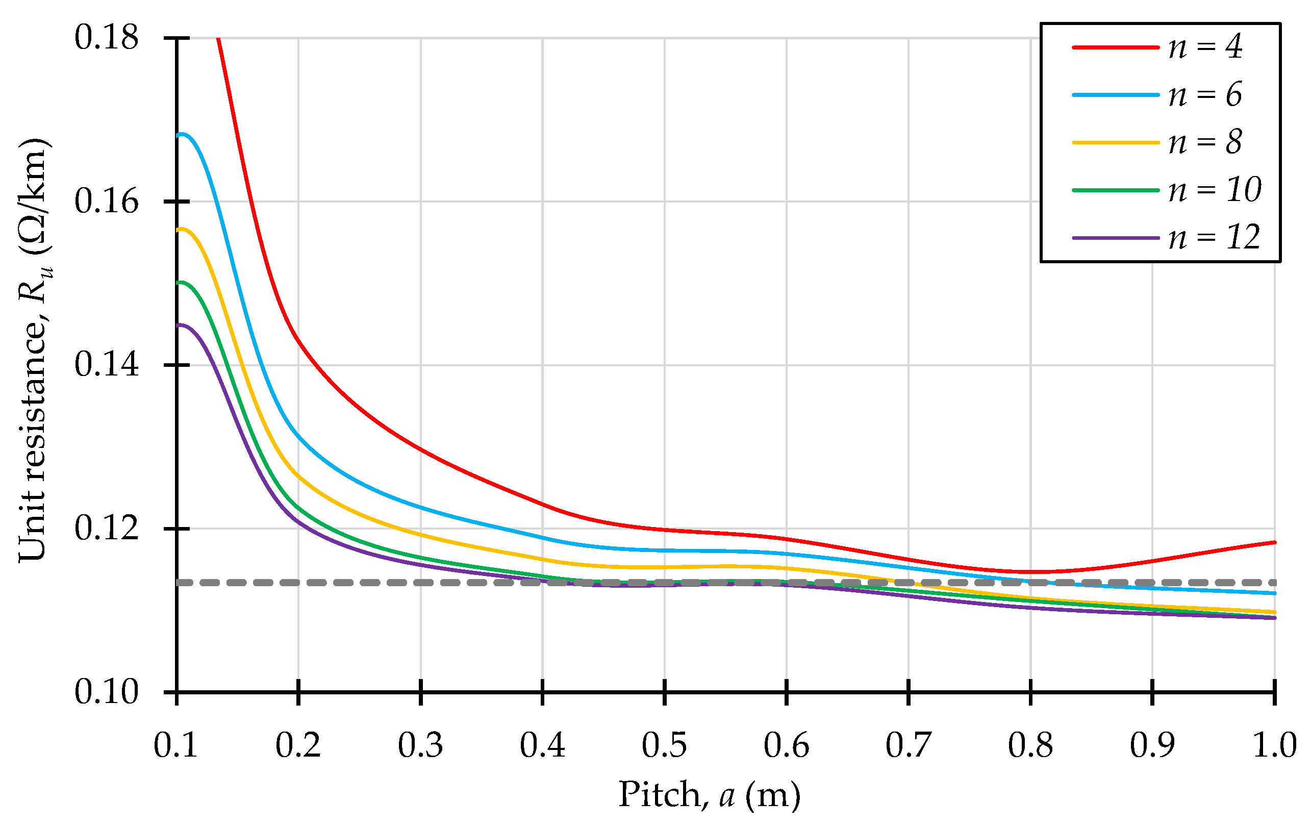
The next step was the identification of DC resistance (Figure 6). It can be observed that nearly straightforward correlation between unit weight (mu) and resistance (Ru) had appeared. For wires with the lower weight the resistance was higher (e.g., for all n at a << 0.3 m), while Ru was lower with higher mu (e.g., for n > 4 and a > 0.7 m). The explanation is simple—less aluminum increases the effective resistance, while adding more material, by wrapping helices at specific pitches, results in reducing the resistance. These findings lead only to knowledge, that before choosing some n and a, the analysis of unit resistance should be performed earlier, to exclude the cases where DC resistance might be too high. Moreover, there were variants where weight of ACSS/nHW was convergent to those of ACSS/TW, yet unit resistance was higher (e.g., for n = 10 or n = 12 and a ≈ 0.26 m the unit resistance was approximately 18% higher). Since Ru of any ACSS/nHW cannot exceed the R, to preserve as low power loss as possible, and mu should not exceed m (to avoid extra material cost and gravity load), only particular structures would be considered, i.e., those which both mu and Ru were close to m and R.
These variants were presented in Table 2 and the differences relative to m and R were also calculated. Based on the values received, it can be said that the worst of these best variants was No. VII (a = 0.78 m, n = 6), where the unit weight was close to m, but unit resistance had grown the most. The most interesting were cases No. III (a = 0.62 m, n = 12) and No. IV (a = 0.65 m, n = 10), suggesting that the slight decrease in mu may lead to lowering of Ru; whilst this looks promising, the numerical errors could have influenced the results, giving a false perception of possibility to obtain this in reality. Reasonable results may be found for No. I (a = 0.5 m, n = 10) and No. II (a = 0.52 m, n = 12), where weight had been reduced a bit, but resistance had grown unnoticeably. Generally speaking, due to such minor differences, it is difficult to highlight an optimal structure of ACSS/nHW. Here, another parameter can be helpful in indicating the best variant, i.e., the one referring to mechanical challenges caused by the environmental factors.
For this reason, it would be valuable to predict the behavior of the wire during various wind conditions. The aerodynamic force will affect the overhead power line, since an outer structure of the conductor will cause drag (and skin friction) [59,60], in N:
F D = 1 2 C D S D g u i n 2 ,
where CD—drag coefficient (depending on the shape of an object), and SD—cross-sectional area (e.g., a longitudinal section of the conductor), in m2. To compare aerodynamic properties of different wires, it would be worth using some characteristic parameters. Nevertheless, the dimensionless drag coefficient, despite its shape dependency, lacks containing the information of a scale of the object, crucial in reviewing ACSS/TW and ACSS/nHW wires which (for identical aluminum cross-section Aa) have clearly different sizes. To also recalculate the results per kilometer of the helical wire with known diameter and length (l), the unit surface S, in m2/km, was introduced as
S = 2 r s + d r + b r l .
It may be worth characterizing wires by the property of combining influence of the shape (included in CD) and size (included in S), specified as the unit drag surface CDS, in m2/km:
C D S = 2 F D l g u i n 2 .
The drag surface helps to compare different wires in terms of causing the aerodynamic load (higher CDS means greater force acting on the wire) or calculate the drag for the other velocities of the wind. The considered 3D model allows us to find FD, so for the applied length l = ½a, known g of the air, and the imposed uin, the unit drag surface can be numerically estimated at any free stream velocity and structure of the wire.
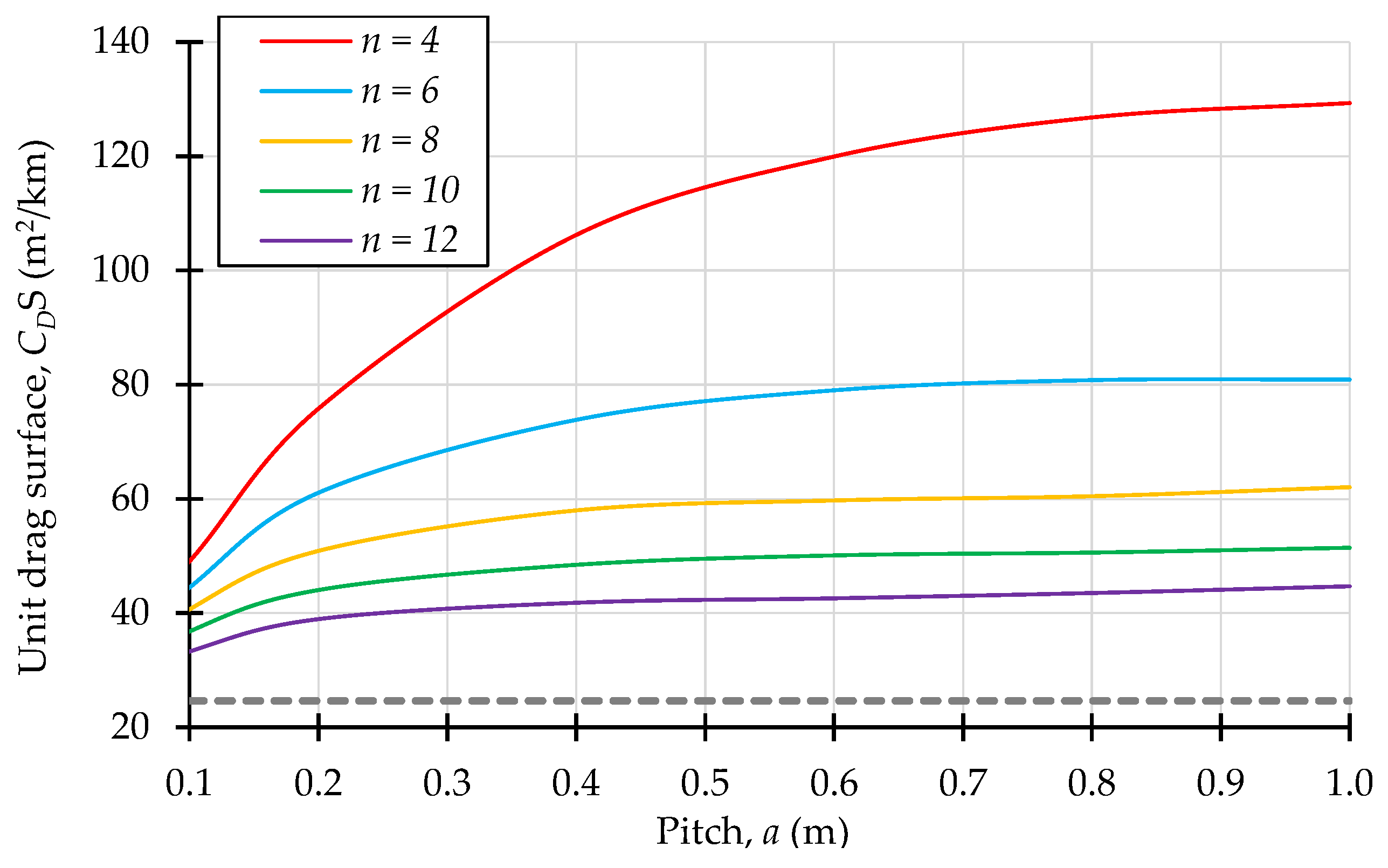
The unit drag surface of any helical wire was much larger than the surface of the considered ACSS/TW conductor (CDSTW = 24.61 m2/km). Figure 7 shows that CDS increased with the pitch, but the number of helices played the most important role. For the wire having only n = 4 helices, the drag surface was even five times larger than CDSTW. Fortunately, more helical wires produced significantly lower values of CDS, e.g., for n = 10 and a < 0.5 m, the unit drag surface reached 49.2 m2/km, being less than two times of CDSTW. With no doubt, the most efficient way to reduce the aerodynamic force caused by wind would be to use ACSS/nHW with shorter outer radius (requiring large n) and to choose the variant with rather small a. Following these suggestions, the best could be the variant No. I (a = 0.5 m, n = 10) from Table 2, while the worst No. VI (since n = 4 causes high CDS). The variants No. II, V and VII can also be analyzed to investigate the potential advantage of heat dissipation using fewer or more helicoids.

3.3. Cooling Efficiency of Helical Conductor

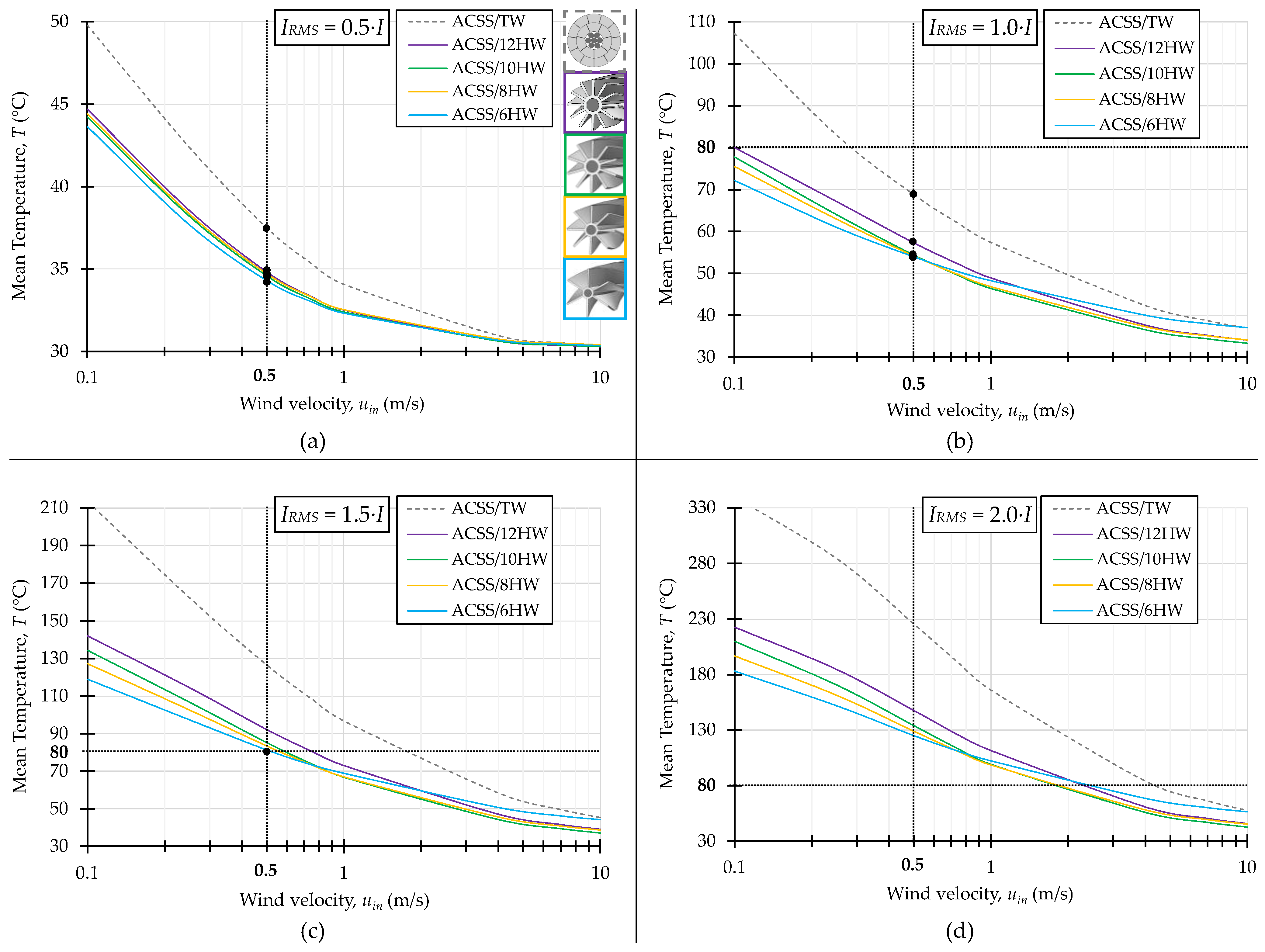
After the initial analysis and choosing the leading variants (No. I—ACSS/10HW, No. II—ACSS/12HW, No. V—ACSS/8HW, and No. VII—ACSS/6HW) their thermal properties and ampacity were discussed. These cases were subjected to further numerical calculations, where four currents (IRMS = 0.5·I, IRMS = 1.0·I, IRMS = 1.5·I, and IRMS = 2.0·I) and different wind velocities (uin) were imposed to find the mean temperatures (T) of wires. The main results were presented in Figure 8, along with the characteristics simulated for ACSS/TW wire (dashed lines). The basic property of reducing T with higher wind speed was present for all considered conductors. Temperatures dropped much below 70 °C above uin ≈ 6 m/s, regardless of IRMS or type of wire. Such wind does not appear commonly in reality yet only indicates that the vital difference between standard and helical conductors must appear at low-speed wind (what is in fact most desirable). Remarkably, helical structures guaranteed lower temperatures than ACSS/TW at any current and velocity of wind. The best one was ACSS/6HW characterized by the lowest T at uin < 1 m/s, while with increasing number of helices, the mean temperature of the conductor was also rising. Situations where the wind and type of wire had a minor importance was for IRMS < I (e.g., IRMS = 0.5·I in Figure 8a), resulting in small differences between ACSS/nHW as well as giving temperatures below 80 °C even for ACSS/TW. In Figure 8b, the specific point can be found for ACSS/TW conductor, i.e., the wind velocity uin ≈ 0.3 m/s where wire reaches T ≈ 80 °C (at speeds uin < 0.3 m/s its mean temperature grows up to 107 °C). Temperature of helical structures, according to Figure 8b, should not exceed 80 °C even for still air (0.1 m/s).
The most interesting states of operation are emphasized in Figure 8 by black dots, placed on the line of uin = 0.5 m/s and below T = 80 °C. These points suggest whether the wire can safely operate with particular IRMS. For example, characteristics of all conductors in Figure 8a,b crossed the indicated velocity of 0.5 m/s below 80 °C. In Figure 8c, where IRMS = 1.5·I, the curve of ACSS/TW passed 0.5 m/s at T = 126.6 °C, meaning that this wire cannot conduct such current enduringly, since at such slow wind, the wire will be overheated. While in the same case, helical wires crossed the boundary of 0.5 m/s, having temperatures from 81.3 °C (ACSS/6HW) to 92.2 °C (ACSS/12HW)—this implies that ACSS/nHW should be able to carry the current approaching IRMS = 1.5·I during long-term operation, even in slow-moving air. This is promising, but probably also represents a limit of increasing the ampacity. In Figure 8d, the case of doubling the nominal current (IRMS = 2.0·I) was considered and all wires could not function if the wind was slower than 0.5 m/s (the closest was ACSS/10HW, achieving 80 °C at uin ≈ 1.8 m/s). Theoretically, then, it can be possible to double the ampacity while using helical structures if one accepts temperature reaching 130 °C at uin = 0.5 m/s. Moreover, if small numbers of helices cause significant problems with the aerodynamic force pushing the wire, based upon Figure 7 and Figure 8, variant No. I can be chosen as an optimum case. As follows from Figure 8c, the ampacity of ACSS/10HW will not grow by 50%, but by 30% ÷ 45% at the same unit weight, unit resistance, cross-section, steel support, and stringent environmental conditions as those of ACSS/TW.
It is also recommended to discuss the effective thermal properties of ACSS wires. The heat balance per unit length (at steady state) can be formulated as
I R M S 2 R u l Internal power loss + 0.5 G η S r Solar irradiation + k ε σ S r T 4 Radiative heating = h S r T T a m b Convective cooling + ε σ S r T 4 Radiative cooling ,
where η—spectral absorption; k—radiative heating coefficient; σ—Stefan–Boltzmann constant, in W/m2·K4; and h—heat transfer coefficient, in W/m2·K. In Equation (17), let us note that
  • Only half of the conductor was lit by the solar light; hence, half of G was used,
  • η = ε, according to Kirchhoff’s law of thermal radiation,
  • A coefficient of radiative heating k was introduced to take into account that helices radiate the heat not only into surrounding open space, but also that some part of the radiated energy returns to neighboring helices,
  • Sr can be analytically calculated using Equations (1) and (2),
  • Ru can be found numerically or analytically.
After numerical identification of heat transfer coefficient (h), shown in Figure 9, and mean values of radiative heating coefficient (k), gathered in Table 3, the maximum nominal current of the conductor can be recalculated for the imposed parameters (T, Tamb, G, ε, and σ) and estimated coefficients (h and k). At the beginning, let us define the unit resistance (i.e., in Ω/km) of aluminum (Ra) and steel parts (Rs) as
R a = β ρ a A a 1 ,
R s = β ρ s A s 1 .
In real-life conditions, the wires are twisted along the length of conductor, resulting in an elongated effective current path. To take this into account, the simplest solution is to use the correction coefficient (β) which will be greater than 1 and less than 2, always leading to the increase in resistance. Next, substituting Equation (3) and Equation (4) into Equation (18) and Equation (19) leads to
R a = β ρ 0 , a 1 + α a T T 0 A a 1 ,
R s = β ρ 0 , s 1 + α s T T 0 A s 1 .
Assuming that aluminum and steel parts were electrically connected in a parallel configuration, the equivalent unit resistance of the wire would be
R u = R a 1 + R s 1 1 .
By incorporating Equation (22) into Equation (17) and transforming them accordingly, the formula for the maximum current (IRMS) of the helical wire can be presented as
I R M S = S r h T T a m b + 1 k ε σ T 4 0.5 G ε A a β ρ 0 , a 1 + α a T T 0 + A s β ρ 0 , s 1 + α s T T 0
This current can be calculated without a numerical model, for any allowable operating temperature (T), since h (at any uin ≤ 10 m/s) can be estimated using Figure 9a and k taken from Table 3, while remaining variables are the environmental constants (σ, G, T, Tamb, and T0) or material parameters (ε, η, ρ0,a, ρ0,s, αa, αs, Aa, As, Sr, and β).
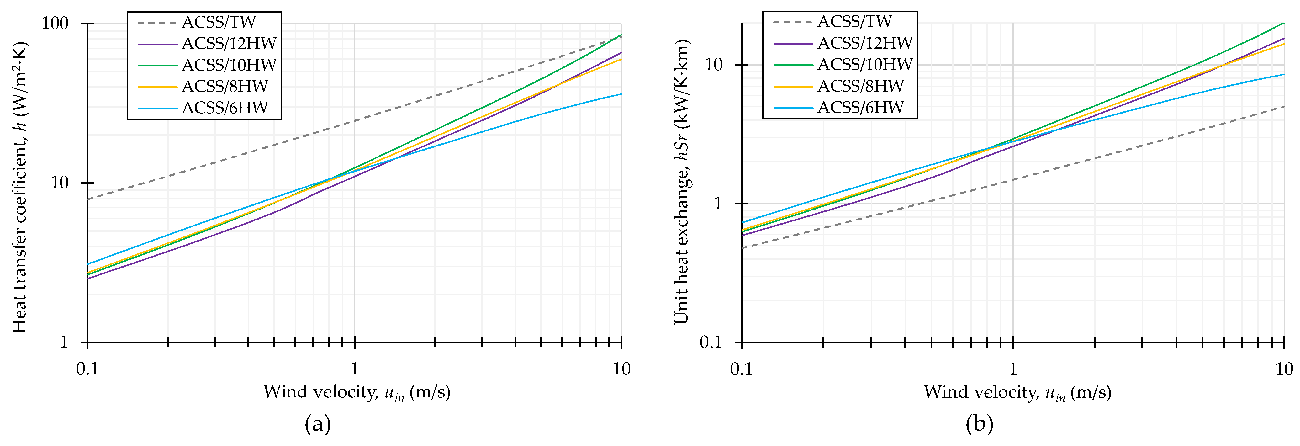
As expected, the heat transfer coefficient (h) rises with increasing speed of wind (Figure 9a). The highest values were observed for the round conductor (ACSS/TW), while for helical wires, h had decreased. It seems that the complicated structure of helices deteriorates the ability of ACSS/nHW wires to transfer the power losses to the air. Still, at uin < 1 m/s, ACSS/6HW exhibited the highest h of four considered helical structures, whereas the lowest heat transfer coefficient was found for ACSS/12HW. At uin > 1 m/s, the tendency changed, since ACSS/10HW was characterized by the highest h of helical wires, while ACSS/6HW started to have the lowest h. This suggests that the convective cooling of ACSS/nHW could be less effective than those of the round conductor and this ability dramatically changes for the different velocities of wind.
However, while commenting on the overall heat transfer efficiency of any conductor, it would be much more advisable to introduce the indicator, named as the unit heat exchange (hSr), as a simple multiplication of the heat transfer coefficient (depending on the shape of object) and the outer surface (associated with the entire external area of object). The hSr helps to compare wires better, since higher values mean more heat transferred to air and lower temperatures of the object. The unit heat exchange (hSr) is presented in Figure 9b. The most effective in transferring heat to the air, at slow moving wind, was ACSS/6HW, as it was also concluded during analysis of Figure 8 and Figure 9a, while the least efficient was ACSS/TW, having hSr nearly 2 ÷ 3 times smaller than ACSS/nHW wires. Hence, the key factor in increasing the convective exchange of heat was not the heat transfer coefficient, but the entire outer surface of ACSS/nHW. By taking both the ability (h) and—the most important—the surface (Sr) radiating the power, it can be noticed that the effective cooling efficiency of the helical wire, compared to a standard conductor, had been boosted noticeably (Figure 9b). Helices act as the fins of aluminum heat sink so a larger surface, arising from more fins, theoretically ensures better heat exchange, although it seems they cannot be short and located too close to each other, which disturbs the airflow, crucial in convective cooling. This was spotted in the most crucial range of a rather slower wind (uin < 1 m/s)—there, the growing n would lead to raise in the temperature of the wire. At relatively faster wind speeds (uin >> 1 m/s), wires with more helices, in contrast, had lower temperatures due to higher hSr; nevertheless, at these velocities of moving air, all wires exhibited satisfyingly low temperatures much below 80 °C. Finally, the total dissipated heat requires us to include radiative cooling, i.e., the last term in Equation (17). Once more, the much larger outer surface of helices, even with the presence of self-heating by this radiation (incorporated in a heat balance by coefficient k), would provide a nearly three times larger amount of radiated power, which also improves the cooling efficiency.
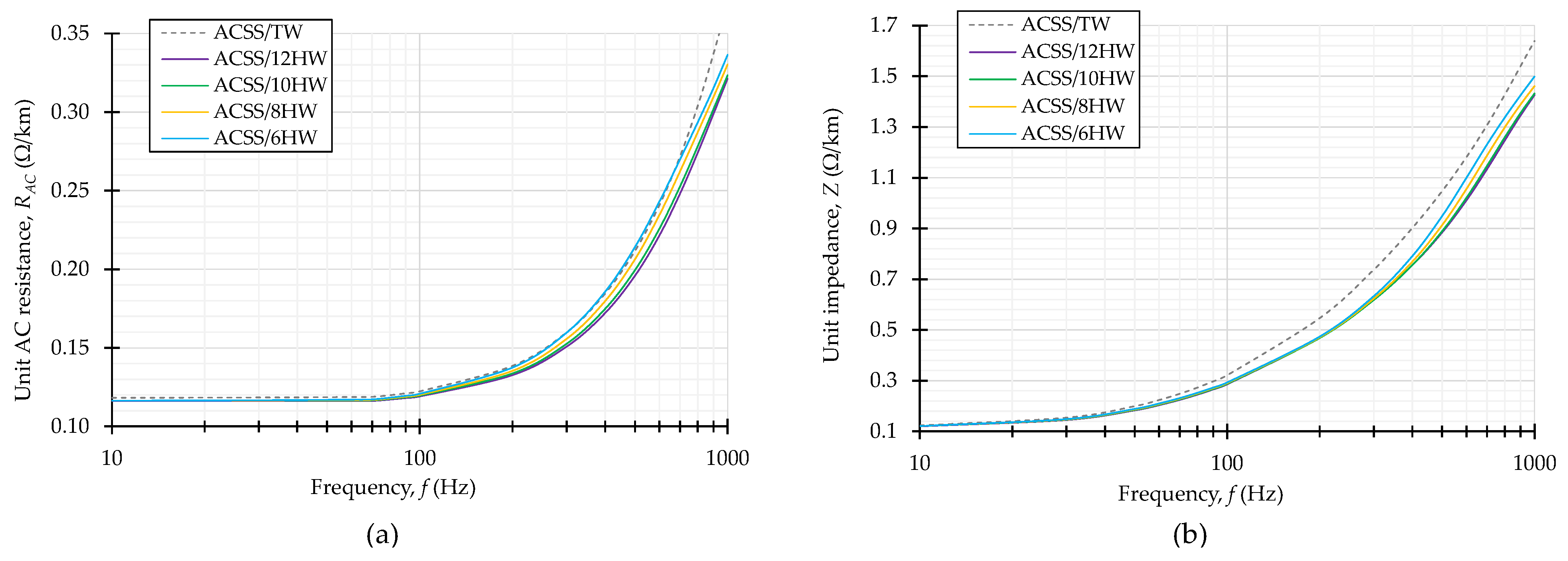
To complement the discussion of electric parameters characterizing ACSS/nHW wires, the simulations of alternating magnetic field was performed, in which Equation (5) was used. The frequency spectrum of 10 to 1000 Hz had been considered as well as magnetic permeability of surrounding air and inner cores were taken into account. The results show that the unit resistance of wire RAC (Figure 10a) should not visibly increase up to 100 Hz, and no important distinction between trapezoidal or helical wire can be found. However, above 200 Hz, the growth of RAC became more dynamic, leading to doubling the resistance at nearly 600 Hz. Then, at 1 kHz, the AC resistance was almost three times higher than at DC current. The same effect was observed for all considered wires; however, the helical structures revealed themselves as less susceptible, with 2–13% smaller AC resistances (depending on frequency). Simultaneously, the impedance grows with frequency, since inductive reactance dominates and increases with the higher frequency. The only positive observation is that ACSS/nHW wires may possess 2–16% lower values of the impedances than ACSS/TW—this came directly from lower values of a unit inductance (e.g., at f = 50 Hz, the unit inductance of ACSS/TW was 509.3 µH/km, while ACSS/12HW had 451.1 µH/km).

3.4. Analysis of Optimal Structure

The last examination was focused on comparing the selected ACSS/10HW wire with the hollow conductor (HC), having identical unit weight and resistance, and a cross-section of the aluminum part and size (diameter). The objective was to closely analyze their properties (ampacity, temperature, and aerodynamic drag) and to identify the most useful solution. The considered hollow/tubular conductor, to fulfill the abovementioned requirements, must have an outer radius of ro = 17.82 mm and inner resection of ri = 15.53 mm. Its shape followed one presented in Figure 1, with a numerical model as in Figure 3.
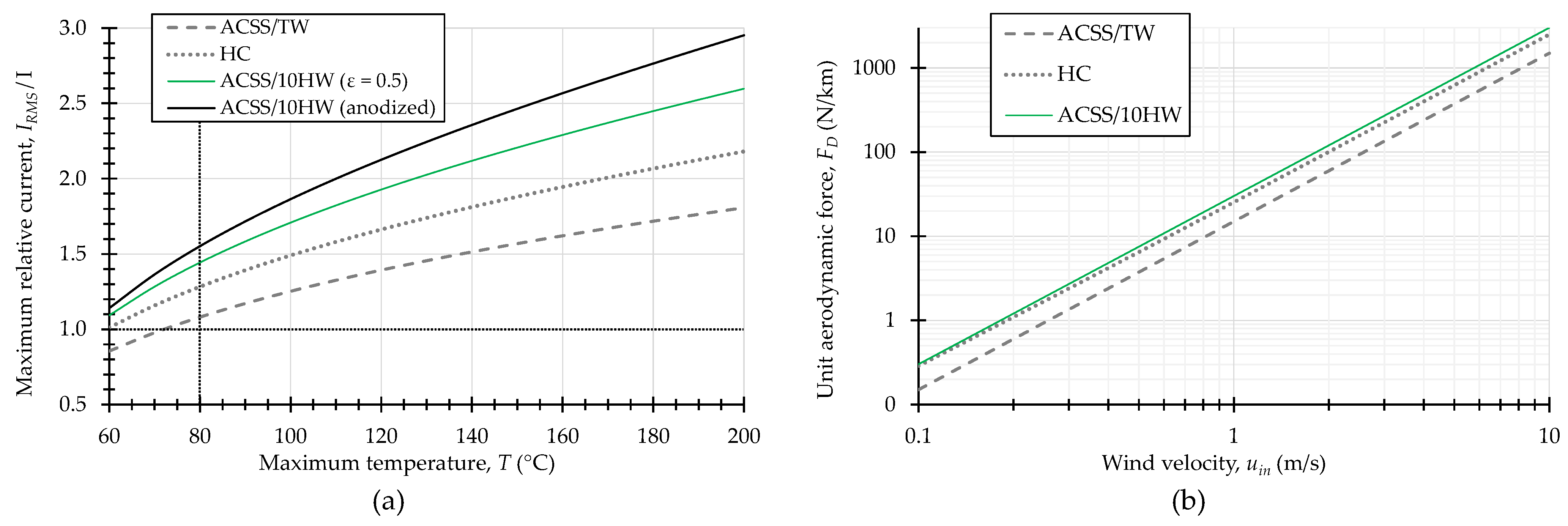
Firstly, let us discuss the maximum ampacity (IRMS) of wires at slow (uin = 0.5 m/s) moving wind for different allowable temperatures of operation (T), shown in Figure 11a, calculated using Equation (23). The temperature of ACSS/TW reached ≈73 °C at IRMS = I, which seems to be correct, since at nominal current (I) and uin = 0.5 m/s, the temperature of 80 °C should not be exceeded (while the results show that at T = 80 °C, the 7.9% higher current could also be admissible). If higher operating temperatures will be permissible (e.g., during a short period of time) then at T = 200 °C, the maximum current could be 81% higher than nominal ampacity. The results were visibly better for the hollow conductor (HC), where at T = 80 °C, the IRMS may increase by 28% and at T = 200 °C, the IRMS even doubled I. However, the best performance was achieved by ACSS/10HW—at T = 80 °C, the ampacity was 44% higher than nominal, while at T = 200 °C, ampacity increased by 160% of I. In other words, at demanding environmental conditions during a sunny day (G = 1000 W/m2) of summer (Tamb = 30 °C) with a calm wind (uin = 0.5 m/s), the helical conductor should be able to ensure ampacity between 36% ÷ 44% higher than ACSS/TW; hence, for I = 620 A, the maximum current of ACSS/10HW may meet IRMS = 893 A. This gain will increase with temperatures above 80 °C, giving even IRMS = 1612 A at T = 200 °C. Situation of T >> 100 °C could be considered as a temporary overloading of an overhead power line and when steel support would be replaced by a composite core/strands.
Equation (23) provides an option to consider the ampacity of the conductor at various environmental conditions (e.g., solar irradiance and ambient temperature), sizes, materials, and their properties. One of them is the emissivity (ε) of the external surface, which affects the ability to radiate heat but also influences the absorption of the wire. It was observed that lower emissivity reduced IRMS at any temperature. This is why the opposite situation was additionally discussed, i.e., the ACSS/10HW conductor having ε = 0.85, which corresponds to emissivity of a black, anodized aluminum [61,62] and probably the highest value technically available. Figure 11a indicates that creating a highly radiative layer could enhance the IRMS by 55% at T = 80 °C and by 195% at T = 200 °C. However, the most interesting was the point of T = 110 °C where IRMS grew by 100%. It was especially engaging, since the ampacity of the overhead power line may be doubled, while the increase of 30 °C could not be disqualified in practice, leading to allowable temperature of T = 110 °C during a long-term operation.
Yet this will likely require using composite strands instead of steel and anodizing the external surface of the helical wires. As a result, the improved version of ACSS/10HW wire might be also proposed as follows: anodized aluminum conductor composite core, ten helices wire (ACCC/10HW), visualized in Figure 12a. It may be able to withstand the mechanical stress at elevated temperatures and will not be suffering due to effects caused by the presence of ferromagnetic steel cores. On the other hand, the anodized layer will not affect the partial discharges, resulting from “sharp” geometry of wire and its usage in the high-voltage systems. To check whether the Corona effect may appear, the extra investigation has been carried out. The ACCC/10HW wire with an applied amplitude of a line-to-ground potential of 110 kV grid, surrounding air, and a grounded metallic sheath (1 m away from the wire) were simulated, to create a potential gradient in the gas between the surface of the conductor and the grounded object. If a breakdown electric field of the air can be assumed at 30 kV/cm level [63], the results in Figure 12b clearly suggest the possibility of partial discharges appearance. The highest electric field was found at the tips of helices reaching nearly 20 kV/cm, while the maximum values of 23.282 kV/cm were present at the edges of these endings. Since simulation simplifies the real conditions, one may notice that maximum values of surface electric field are close to the 30 kV/cm limit. At any unfavorable outdoor conditions, through sharpening the tips of helices or an increase in the nominal grid voltage, the Corona effect is likely to appear at the outermost edges of wire.
It is also worth analyzing the influence of the structure modification by widening its helices/inner tube. During the previous examinations, these parameters (wr and dr) were constant, yet they may change the equivalent parameters of the line constructed of helical wires. In Figure 12c,d, the relative differences of AC resistance and impedance had been shown for the considered frequency range 10 ÷ 1000 Hz and three variants with doubled wr and/or dr. The general rule cannot be easily identified; however, it can be noticed that widening the helix leads to a reduction in both electrical parameters by 0.5 ÷ 7%, while widening the tube may rather increase the impedance (and resistance at high frequencies). Unfortunately, such modifications of the cross-section shape, shown in the inserts in Figure 12d, have a disadvantage of shortening the height of helix, while this will decrease the outer surface and therefore the passive cooling ability of helical wire.
The last quantity under discussion was the aerodynamic force acting on a lateral surface of the conductor. The lowest drag was found for ACSS/TW, since its outer diameter was the smallest. The utilization of HC will cause an increase in the force by 67% ÷ 92%, depending on the wind velocity, compared to ACSS/TW. The highest force pushing the conductor would be expected for ACSS/10HW (or ACCC/10HW), where the aerodynamic drag may rise by approximately 99%. It means that the difference between HC and ACSS/10HW was not significant, as it is depicted as well in Figure 11b. The higher ampacity, resulting from the improved passive cooling efficiency, of a helical structure seems to be more advantageous than the moderately lower drag of tubular conductor with the same size. By analyzing the juxtaposition of considered conductors (Table 4), it can be suggested that the most promising, particularly in improving the power line capacity, was ACCC/10HW with anodized surface and potentially elevated operational temperature.

4. Conclusions

The article was devoted to theoretical analysis of possible properties of the high-voltage conductors with a helical structure, abbreviated as ACSS/nHW. The wires considered were formed of many helical ribbons stretched along the length of an overhead power line. Such a design enlarged the total area several times, compared to the standard round conductor having an identical cross-section, steel reinforcement, as well as unit weight and resistance. The larger external surface of the conductor enhanced the heat dissipation by both improving the convective and radiative energy exchange with the outer space (environment). The helical wires may ensure unique characteristics, unavailable in the classic solution or even for hollow conductors with the same dimensions (diameter, cross-section).
The wire with a cross-section of 240 mm2 was put under investigation and a three-dimensional numerical model was created to consider the conjugated electric, thermal, pressure and velocity fields. Theoretical calculations showed that number of helices and pitches (at which they were wrapped) nonlinearly affected the amount of material used. The preliminary analysis of the unit weight and direct current resistance at 20 °C should be then performed, to identify the variants having these parameters at least the same as the ACSS/TW conductor. Furthermore, the large number of helices forming the structure and larger pitch negatively influenced the aerodynamic force acting on the lateral surface—the drag may grow by two or even five times. Hence, ACSS/nHW, with a rather higher number of helices and smallest possible pitch, should be chosen.
The results indicated that helical wires could be able to increase an ampacity by even 30% ÷ 50%, compared to the nominal current of ACSS/TW, in the demanding environmental conditions of operating in summer, with a full solar irradiance, slow wind (<1 m/s), and the maximum allowable temperature of T = 80 °C. At higher temperatures (100 °C < T < 150 °C) allowed during, e.g., a short-time operation, the capacity of a power line may be enhanced further by approximately 50% ÷ 60% (compared to the standard wire). The best of all introduced helical structures was ACSS/10HW, with ten helices and a half-meter pitch. Additional studies showed that this variant should raise the ampacity by 44%, giving the maximum current of 895 A (at a long-term operating temperature of 80 °C and wind velocity of 0.5 m/s) instead of 620 A (nominal current of ACSS/TW), with the disadvantage of two times higher aerodynamic force pushing the conductor. Finally, based on equations derived, the other version of this wire was discussed, i.e., with a composite core and an anodized outer surface (possessing a higher emissivity). The anodized aluminum contributed positively to a heat balance by improving the cooling efficiency even more, while fiber strands provide effective mechanical reinforcement. Thus, when examining ACCC/10HW, it was also proposed to potentially permit an elongated operation with a wire temperature of 110 °C, since the overhead power line capacity could be doubled at such conditions. This might open the opportunity to receive the raised amount of power produced regularly and/or intermittently by photovoltaics and other renewable sources. Yet, further research should be conducted and focus on an experimental verification of the presented findings. Also, the proposition of reducing the drag as well as an examination of forces acting on these structures (during hanging on the power poles) ought to be performed in future. Before practical implementation, the spiral shape of ACSS/nHW has to be examined in terms of the structural mechanics and safety requirements specified in the standards (e.g., DL/T 741-2010). The swaying of the wires during strong gusts of wind may result in electrical arcs between phases, so the joint wind deflection flashover simulations will be necessary, along with stress distribution examinations, within any further work.

Author Contributions

Conceptualization, A.S.; methodology, A.S. and M.Z.; software, A.S.; validation, A.J. and M.Z.; formal analysis, M.Z., A.J. and A.S.; investigation, A.S. and A.J.; resources, A.J.; data curation, A.J.; writing—original draft preparation, A.S.; writing—review and editing, M.Z. and A.J.; visualization, A.S.; supervision, M.Z.; project administration, M.Z. and A.J.; funding acquisition, M.Z. All authors have read and agreed to the published version of the manuscript.

Funding

This research was funded by the Ministry of Science and Higher Education in Poland at the Bialystok University of Technology under research subsidy No. WZ/WE-IA/7/2023 and as a part of work WZ/WE-IA/3/2023.

Data Availability Statement

The original contributions presented in this study are included in the article. Further inquiries can be directed to the corresponding author. The materials would be available to interested researchers upon request.

Conflicts of Interest

The authors declare no conflicts of interest.

References

  1. De Santis, D.; James, B.D.; Houchins, C.; Saur, G.; Lyubovsky, M. Cost of long-distance energy transmission by different carriers. iScience 2021, 24, 103495. [Google Scholar] [CrossRef]
  2. Prasad Rao, K.P.; Srinivasa Varma, P. Analysis of very long distance AC power transmission line. In Proceedings of the 2017 International Conference on Electrical, Electronics, Communication, Computer, and Optimization Techniques (ICEECCOT), Mysuru, India, 15–16 December 2017. [Google Scholar]
  3. Wu, X.; Yang, X.; Shen, H.; Zhou, Q. Research on the Long-distance Transmission. Energy Power Eng. 2013, 5, 1293–1297. [Google Scholar] [CrossRef]
  4. Dwivedi, A.; Rajbhar, P.; Tiwari, N.M. Long Distance Power Transfer Technique: A Review. J. Robot. Mechatron. 2019, 3, 208–214. [Google Scholar] [CrossRef]
  5. Lienert, P.; Sutterlin, B.; Siegrist, M. Public acceptance of high-voltage power lines: The influence of information provision on undergrounding. Energy Policy 2018, 112, 305–315. [Google Scholar] [CrossRef]
  6. Yin, J.; Wei, Q.; Shao, D.; Luo, Z.; Ji, L. The impacts of power transmission and transformation projects on ecological corridors and landscape connectivity: A case study of Shandong province, China. Sci. Rep. 2025, 15, 6709. [Google Scholar] [CrossRef]
  7. Tempesta, T.; Vecchiato, D.; Girardi, P. The landscape benefits of the burial of high voltage power lines: A study in rural areas of Italy. Landsc. Urban Plan. 2014, 126, 53–64. [Google Scholar] [CrossRef]
  8. Nowak, W.; Tarko, R. Analysis of electrical shock hazard caused by electromagnetic coupling effects in parallel overhead high-voltage power lines. IET Gener. Transm. Distrib. 2018, 12, 3398–3404. [Google Scholar] [CrossRef]
  9. Hoger, M.; Regul’a, M.; Roch, M. Investigating the impacts of high voltage powerlines on ground current fields. Transp. Res. Proc. 2023, 74, 900–907. [Google Scholar] [CrossRef]
  10. Chojnacki, A.Ł. Modelling the influence of atmospheric conditions represented by wind, precipitation and air temperature on the intensity of failure and restoration time of medium-voltage power lines. Sustain. Energy Grids Netw. 2025, 42, 101652. [Google Scholar] [CrossRef]
  11. Larsen, P.H. A method to estimate the costs and benefits of undergrounding electricity transmission and distribution lines. Energy Econ. 2016, 60, 47–61. [Google Scholar] [CrossRef]
  12. Rambonilaza, T.; Dube, J.; Ay, J.-S. External costs of high-voltage overhead transmission lines: Evidence from a causal approach in rural France. Environ. Impact Assess. Rev. 2024, 109, 107639. [Google Scholar] [CrossRef]
  13. Fenrick, S.A.; Getachew, L. Cost and reliability comparisons of underground and overhead power lines. Util. Policy 2012, 20, 31–37. [Google Scholar] [CrossRef]
  14. Nuchprayoon, S.; Chaichana, A. Cost evaluation of current uprating of overhead transmission lines using ACSR and HTLS conductors. In Proceedings of the 2017 IEEE International Conference on Environment and Electrical Engineering and 2017 IEEE Industrial and Commercial Power Systems Europe (EEEIC/I&CPS Europe), Milan, Italy, 6–9 June 2017. [Google Scholar]
  15. Gębczyk, K.; Chojnacki, A.Ł.; Grąkowski, Ł.; Banasik, K. Comparative analysis of the costs of medium voltage overhead and cable lines failure. Przegląd Elektrotechniczny 2020, 96, 84–90. [Google Scholar] [CrossRef]
  16. Cost Analysis of Electrical Conductors: A Comprehensive Study. Available online: https://elkamehr.com/en/cost-analysis-of-electrical-conductors-a-comprehensive-study/ (accessed on 11 September 2025).
  17. Strielkowski, W.; Civín, L.; Tarkhanova, E.; Tvaronavičienė, M.; Petrenko, Y. Renewable Energy in the Sustainable Development of Electrical Power Sector: A Review. Energies 2021, 14, 8240. [Google Scholar] [CrossRef]
  18. Qin, B.; Wang, H.; Liao, Y.; Li, H.; Ding, T.; Wang, Z.; Li, F.; Liu, D. Challenges and opportunities for long-distance renewable energy transmission in China. Sustain. Energy Technol. Assess. 2024, 69, 103925. [Google Scholar] [CrossRef]
  19. Tian, J.; Culley, S.A.; Maier, H.R.; Zecchin, A.C. Is renewable energy sustainable? Potential relationships between renewable energy production and the Sustainable Development Goals. npj Clim. Action 2024, 3, 35. [Google Scholar] [CrossRef]
  20. Loschel, A.; Managi, S. Recent Advances in Energy Demand Analysis—Insights for Industry and Households. Resour. Energy Econ. 2019, 56, 1–5. [Google Scholar] [CrossRef]
  21. Hina, H.; Abbas, F.; Qayyum, U. Selecting correct functional form in consumption function: Analysis of energy demand at household level. PLoS ONE 2022, 17, e0270222. [Google Scholar] [CrossRef]
  22. Malka, L.; Bidaj, F.; Kuriqi, A.; Jaku, A.; Roçi, R.; Gebremedhin, A. Energy system analysis with a focus on future energy demand projections: The case of Norway. Energy 2023, 272, 127107. [Google Scholar] [CrossRef]
  23. Al-Yasiri, A.J. Global Energy Demand For Different Energy Sources: Current Status and Future Prospects. Akkad J. Contemp. Econ. Stud. 2021, 1, 35. [Google Scholar] [CrossRef]
  24. Rani, S.; Jayapragash, R. Review on electric mobility: Trends, challenges and opportunities. Results Eng. 2024, 23, 102631. [Google Scholar] [CrossRef]
  25. Muratori, M.; Alexander, M.; Arent, D.; Bazilian, M.; Cazzola, P.; Dede, E.M.; Farrell, J.; Gearhart, C.; Greene, D.; Jenn, A.; et al. The rise of electric vehicles—2020 status and future expectations. Prog. Energy 2021, 3, 022002. [Google Scholar] [CrossRef]
  26. Adamo, A.; Martin, H.; de la Hoz, J.; Rubio, J. A Review of Worldwide Strategies for Promoting High-Temperature Heat Pumps. Appl. Sci. 2025, 15, 839. [Google Scholar] [CrossRef]
  27. Akbarzadeh, S.; Sefidgar, Z.; Valipour, M.S.; Elmegaard, B.; Arabkoohsar, A. A comprehensive review of research and applied studies on bifunctional heat pumps supplying heating and cooling. Appl. Therm. Eng. 2024, 257, 124280. [Google Scholar] [CrossRef]
  28. Kishore, T.S.; Selvaraj, M.; Singal, S.K. Methodology for cost estimation of overhead power transmission lines. Int. J. Power Energy Convers. 2017, 8, 132–145. [Google Scholar] [CrossRef]
  29. Larruskain Eskobal, D.M.; Zamora, I.; Abarrategui, O.; Iraolagoitia, A.; Gutiérrez, M.D.; Loroño, E.; de la Bodega, F. Power transmission capacity upgrade for overhead lines. Renew. Energy Power Qual. J. 2006, 4, 132–145. [Google Scholar] [CrossRef]
  30. Lequien, F.; Auzoux, Q.; Moine, G.; Rousseau, M.; Pasquier-Tilliette, S.; Holande, A.; Ammi, S.; Heurtault, S.; Prieur, P. Characterization of an aluminum conductor steel reinforced (ACSR) after 60 years of operation. Eng. Fail. Anal. 2021, 120, 105039. [Google Scholar] [CrossRef]
  31. Kanálik, M.; Margitová, A.; Urbanský, J.; Beňa, L. Temperature Calculation of Overhead Power Line Conductors According to the CIGRE Technical Brochure 207. In Proceedings of the 2019 20th International Scientific Conference on Electric Power Engineering (EPE), Kouty nad Desnou, Czech Republic, 15–17 May 2019. [Google Scholar]
  32. Riba, J.-R.; Liu, Y.; Moreno-Eguilaz, M. Analyzing the role of emissivity in stranded conductors for overhead power lines. Int. J. Elec. Power Energy Syst. 2024, 159, 110027. [Google Scholar] [CrossRef]
  33. Practical Considerations for ACSR Cable Selection. Available online: https://cable-uni.com/cases/cable-news/practical-considerations-for-acsr-cable-selection.html (accessed on 11 September 2025).
  34. Power System Engineering & Technology Development Central Electricity Authority. Guidelines for Rationalised Use of High Performance Conductors. Available online: https://cea.nic.in/old/reports/others/ps/psetd/guidelines_conductors.pdf (accessed on 11 September 2025).
  35. Seppa, T.; Deve, H.; Watt, G.; Didier, B.; Yonezawa, K.; Hoffman, S.; Iglesias, J.; Brahe, B.; Ueda, S.; Lundquist, J.; et al. Conseil international des grands réseaux électriques. In Guide for Qualifying High Temperature Conductors for Use on Overhead Transmission Lines; CIGRÉ: Paris, France, 2010. [Google Scholar]
  36. Thrash, F.R. ACSS/TW-an improved high temperature conductor for upgrading existing lines or new construction. In Proceedings of the 2001 Power Engineering Society Summer Meeting Conference Proceedings (Cat. No.01CH37262), Vancouver, Canada, 15–19 July 2001. [Google Scholar]
  37. de Miranda, T.B.; Kalombo, R.B.; Araújo, J.A.; de Almeida Ferreira, J.L. Self-damping of conductors AAC, AAAC and ACSR with respect of H/W parameter. In Proceedings of the 25th ABCM International Congress of Mechanical Engineering, Uberlandia, Brazil, 20–25 October 2019. [Google Scholar]
  38. Mohtar, S.N.; Jamal, N.; Sulaiman, M. Analysis of all aluminum conductor (AAC) and all aluminum alloy conductor (AAAC). In Proceedings of the 2004 IEEE Region 10 Conference TENCON 2004, Chiang Mai, Thailand, 21–24 November 2004. [Google Scholar]
  39. Zainuddin, N.M.; Rahman, M.S.A.; Kadir, Z.; Nik Ali, N.H.B.; Zanyar, A.; Osman, M.; Mansor, M.; Ariffin, A.H.; Rahman, M.S.A.; Nor, S.F.H.; et al. Review of Thermal Stress and Condition Monitoring Technologies for Overhead Transmission Lines: Issues and Challenges. IEEE Access 2020, 8, 120053–120081. [Google Scholar] [CrossRef]
  40. Smyrak, B. Analysis of the quality of aluminum overhead conductors after 30 years of operation. Eng. Fail. Anal. 2023, 154, 107600. [Google Scholar] [CrossRef]
  41. Miyazaki, H.; Kitamura, S. Temperature distribution within an ACSR conductor during large current flow. Electr. Eng. Jpn. 2002, 140, 38–45. [Google Scholar] [CrossRef]
  42. Pawlak, U.; Pawlak, M. Type of Material in the Pipes Overhead Power Lines Impact on the Distribution on the Size of the Overhang and the Tension. IOP Conf. Ser. Mater. Sci. Eng. 2017, 245, 022058. [Google Scholar] [CrossRef]
  43. Margita, F.; Beňa, Ľ.; Malska, W.; Pijarski, P. Possibilities of Increasing the Ampacity of Overhead Lines Using High-Temperature Low-Sag Conductors in the Electric Power System of the Slovak Republic. Appl. Sci. 2024, 14, 7846. [Google Scholar] [CrossRef]
  44. Riba, J.-R.; Bogarra, S.; Gómez-Pau, Á.; Moreno-Eguilaz, M. Uprating of Transmission Lines by Means of HTLS Conductors for Sustainable Growth: Challenges, Opportunities, and Research Needs. Renew. Sustain. Energy Rev. 2020, 134, 110334. [Google Scholar] [CrossRef]
  45. Evoenergy. Overhead Distribution Line Design Manual. Available online: https://www.evoenergy.com.au/-/media/Project/Evoenergy/EVO/Documents/Manuals/PO07132-Overhead-Line-Distribution-Design-Manual.pdf (accessed on 11 September 2025).
  46. Gołębiowski, J.; Zaręba, M. Analytical modelling of the transient thermal field of a tubular bus in nominal rating. COMPEL 2019, 38, 642–656. [Google Scholar] [CrossRef]
  47. Gao, Y.; Chen, L.Y.; Zhang, L.M.; Huang, S.H.; Du, B.X.; Wang, F. PD characteristics in PTFE insulated tubular busbar models measured with HFCT and acoustic sensor. In Proceedings of the 2015 IEEE 11th International Conference on the Properties and Applications of Dielectric Materials (ICPADM), Sydney, Australia, 19–22 July 2015. [Google Scholar]
  48. Paul, V.J. A Review of Geometry Investigations of Helicoids. IOP Conf. Ser. Mater. Sci. Eng. 2018, 371, 012029. [Google Scholar] [CrossRef]
  49. Kasap, S.O. Principles of Electronic Materials and Devices; McGraw–Hill: Boston, MA, USA, 2006; pp. 127–129. [Google Scholar]
  50. Steckiewicz, A.; Konopka, K.; Choroszucho, A.; Stankiewicz, J.M. Temperature Measurement at Curved Surfaces Using 3D Printed Planar Resistance Temperature Detectors. Electronics 2021, 10, 1100. [Google Scholar] [CrossRef]
  51. Soucek, O.; Martinec, Z.; Velimsky, J. Vector potential formulation of a quasi-static EM induction problem: Existence, uniqueness and stability of the weak solution. Int. J. Geomath. 2011, 2, 265–279. [Google Scholar] [CrossRef]
  52. Roslan, S.N.; Hoe, Y.S. Numerical Solutions of 2D Poisson Equation Using Finite Element Method and Finite Difference Method. Proc. Sci. Math. 2024, 23, 99–107. [Google Scholar]
  53. COMSOL. Linearized Navier-Stokes Model. Available online: https://doc.comsol.com/5.4/doc/com.comsol.help.aco/aco_ug_aero.07.026.html (accessed on 11 September 2025).
  54. EN 50540:2010; Conductors for Overhead Lines—Aluminium Conductors Steel Supported (ACSS). CENELEC: Brussels, Belgium, 2010. Available online: https://standards.cencenelec.eu/ords/f?p=CENELEC:110:::::FSP_PROJECT,FSP_ORG_ID:45725,1258751&cs=1576CA9F8F5D3514BF2E5A7EC91AE1FA9 (accessed on 11 September 2025).
  55. Midal Cables. CONDUCTOR DATA SHEET Aluminum Conductors Steel Supported-Trapezoidal (ACSS/TW). Available online: https://www.midalcable.com/storage/products/acsstw/acsstw-metric.PDF (accessed on 11 September 2025).
  56. Alberdi, R.; Fernandez, E.; Albizu, I.; Bedialauneta, M.T.; Fernandez, R. Overhead Line Ampacity Forecasting and a Methodology for Assessing Risk and Line Capacity Utilization. Int. J. Electr. Power Energy Syst. 2021, 133, 107305. [Google Scholar] [CrossRef]
  57. Katona, T.; Bartsch, A. Estimation of wind speed over lakes in Central Europe using spaceborne C-band SAR. Eur. J. Remote Sens. 2018, 51, 921–931. [Google Scholar] [CrossRef]
  58. Araźny, A.; Przybylak, R.; Vizi, Z.; Kejna, M.; Maszewski, R.; Uscka-Kowalkowska, J. Mean and extreme wind velocities in Central Europe 1951-2005 (on the basis of data from NCEP/NCAR reanalysis project). Geogr. Pol. 2007, 80, 69–78. [Google Scholar]
  59. Eguchi, Y.; Kikuchi, N.; Kawabata, K.; Yukinoc, T.; Ishikubo, Y. Drag reduction mechanism and aerodynamic characteristics of a newly developed overhead electric wire. Wind. Eng. Ind. Aerodyn. 2002, 90, 293–304. [Google Scholar] [CrossRef]
  60. Li, D.Q.; Li, Z.; Liu, Z.; Liu, L.; Yang, C.L.; Fan, W.; Yang, L.Y.; Si, J.J. Application Research on Drag Reduced Conductors for Electric Power Transmission Lines in Strong Wind Areas. MATEC Web Conf. 2014, 44, 01093. [Google Scholar] [CrossRef]
  61. Park, J.; Son, K.; Lee, J.; Kim, D.; Chung, W. Effects of Anodizing Conditions on Thermal Properties of Al 20XX Alloys for Aircraft. Symmetry 2021, 13, 433. [Google Scholar] [CrossRef]
  62. Gustavsen, A.; Berdahl, P.H. Spectral Emissivity of Anodized Aluminum and the Thermal Transmittance of Aluminum Window Frames. J. Build. Phys. 2003, 3, 0103. [Google Scholar]
  63. Riba, J.-R. Studying the breakdown electric field in uniform and non-uniform air gaps. Eur. J. Phys. 2024, 45, 045205. [Google Scholar] [CrossRef]
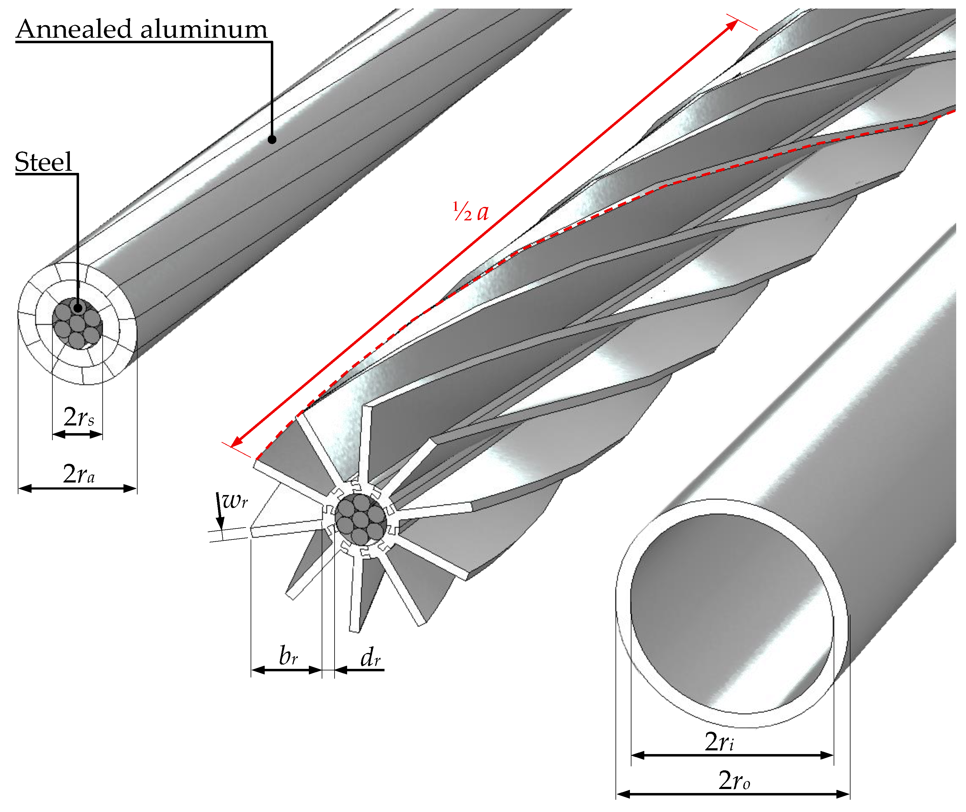
Figure 1. Exemplary overhead conductors: typical ACSS/TW (left); helical wire (center) with the equivalent cross-section and steel support as ACSS/TW; and hollow conductor (right) having an identical outer diameter and cross-section of helical aluminum wires.
Energies 18 06008 g001
Figure 2. The outer surface of helical conductor (Sr) compared to the outer surface of ACSS/TW wire (Sc): (a) for a smaller cross-section (Aa = 120 mm2, dr = 2 mm, wr = 1.5 mm); (b) for a larger cross-section (Aa = 240 mm2, dr = 2 mm, wr = 1.5 mm).
Energies 18 06008 g002
Figure 3. Sketch of the numerical model: the analyzed conductor in the center conducted a current; the air was moved from the input boundary at the left to the output on the right, simulating wind flown around the wire. To assure symmetry, the periodic flow and heat boundary conditions were used on the front and back, while slip wall boundary conditions were added at upper and lower surfaces. To include the effects of radiation heating, irradiance was also assigned.
Energies 18 06008 g003
Figure 4. Analyzed models of ACSS/nHW wires having identical cross-sections of aluminum and steel support with (a) four helices; (b) six helices; (c) eight helices; (d) ten helices; and (e) twelve helices.
Energies 18 06008 g004
Figure 5. The unit weight of ACSS/nHW conductors with different number of helices and pitches, compared to ACSS/TW wire (insert) having the unit weight m = 664.78 kg/km (grey dashed line).
Energies 18 06008 g005
Figure 6. The unit resistance of ACSS/nHW conductors with different numbers of helices and pitches, compared to ACSS/TW wire having unit resistance R = 0.1134 Ω/km (grey dashed line).
Energies 18 06008 g006
Figure 7. The unit drag surface of ACSS/nHW conductors with different numbers of helices and pitches, compared to ACSS/TW wire (grey dashed line).
Energies 18 06008 g007
Figure 8. Mean temperatures of ACSS/nHW wires (solid lines) and ACSS/TW (dashed grey) for four currents at different wind velocities: (a) IRMS = 0.5·I; (b) IRMS = 1.0·I; (c) IRMS = 1.5·I; and (d) IRMS = 2.0·I.
Energies 18 06008 g008
Figure 9. Thermal properties of ACSS/nHW and ACSS/TW conductors at IRMS = I and various wind velocities: (a) heat transfer coefficient; (b) unit thermal transfer.
Energies 18 06008 g009
Figure 10. Frequency spectrum of electrical parameters of ACSS/TW and ACSS/nHW wires: (a) unit resistance at alternating current; (b) unit impedance.
Energies 18 06008 g010
Figure 11. The comparison of ACSS/TW, HC, and ACSS/10HW conductors: (a) maximum relative current at uin = 0.5 m/s and various maximum temperatures of wires; (b) unit aerodynamic force.
Energies 18 06008 g011
Figure 12. The ACCC/10HW with anodized external surface and composite core: (a) simplified visualization; (b) electric field on the surface (110 kV grid); (c) relative change in AC resistance for wires with widened helices and inner tubes; and (d) relative change in impedance of these wires.
Energies 18 06008 g012
Table 1. The parameters used in the numerical model.
NameSymbolValueUnit
Ambient temperatureTamb303.15K
Reference temperatureT0293.15K
Solar irradianceG1000W/m2
Emissivity (aluminum)ε0.5
Density (air)gair1.22kg/m3
Density (aluminum)ga2700kg/m3
Density (steel)gs7850kg/m3
Heat capacity (air)Cp,air1000J/kg·K
Heat capacity (aluminum)Cp,a900J/kg·K
Heat capacity (steel)Cp,s470J/kg·K
Thermal conductivity (air)λair0.0266W/m·K
Thermal conductivity (aluminum)λa234.2W/m·K
Thermal conductivity (steel)λs50W/m·K
Heat capacity ratio (air)γ1.4
Dynamic viscosity (air)ν19.5·× 10−6Pa·s
Relative permeability (aluminum, air)μa1
Relative permeability (steel)μs100
Electrical resistivity (aluminum)ρ0,a2.83·× 10−8Ω·m
Electrical resistivity (steel)ρ0,s1.7·× 10−7Ω·m
Temperature coefficient (aluminum)αa0.004081/K
Temperature coefficient (steel)αs0.0031/K
Cross-section (aluminum)Aa240mm2
Cross-section (steel)As39.2mm2
Radius of steel supportrs4.05mm
Width of helixwr1.5mm
Thickness of inner tubedr2mm
Table 2. The chosen variants of ACSS/nHW wires able to substitute the standard conductors.
No.Pitch,
a (m)
Number of Helices, nUnit Weight,
mu (kg/km)
Relative
Difference Δm
Unit Resistance,
Ru (Ω/km)
Relative
Difference ΔR
I0.5010662.757−0.30%0.11360.18%
II0.5212662.875−0.29%0.11370.26%
III0.6212664.345−0.07%0.1128−0.53%
IV0.6510664.275−0.08%0.1126−0.71%
V0.708667.2420.37%0.1126−0.71%
VI0.754665.4540.10%0.1106−2.47%
VII0.786664.8210.01%0.11430.79%
Table 3. Numerically estimated radiative heating coefficient (k) of wires, averaged for all velocities.
No.NameNumber of Helices, nRadiative Heating
Coefficient, k
IACSS/10HW100.195
IIACSS/12HW120.200
VACSS/8HW80.159
VIIACSS/6HW60.198
ACSS/TW0
Table 4. The summary of properties estimated for the analyzed conductors.
NameMechanical
Reinforcement
Transport and
Installation
Ampacity at
80 °C, 0.5 m/s
Ampacity at
110 °C, 0.5 m/s
Aerodynamic Load
ACSS/TWsteel (can be changed to composite)easy669 A822 Alowest
HCnonemore difficult793 A980 Anearly twice
as ACSS/TW
ACSS/10HWsteelmore difficult895 A1130 Atwice as ACSS/TW
ACCC/10HWcomposite strand/fibersmuch more
difficult
962 A1240 Atwice as ACSS/TW
Disclaimer/Publisher’s Note: The statements, opinions and data contained in all publications are solely those of the individual author(s) and contributor(s) and not of MDPI and/or the editor(s). MDPI and/or the editor(s) disclaim responsibility for any injury to people or property resulting from any ideas, methods, instructions or products referred to in the content.