Abstract
The planetary bearing looseness fault can cause the planetary gear train to fail. Conventional modeling methods do not consider complex component-coupling relationships for fault feature analysis. As a result, a joint model is developed to examine the dominant relationship between planetary bearings and the planetary gear train. Firstly, the planetary bearing is modeled in the normal and fault states. Then, a refined joint planetary gear train dynamic model is constructed, which is composed of the planetary gears, the ring gear, the carrier, the sun gear, and the planetary bearings. Finally, the simulation results show that, when the planetary bearing is in the looseness fault state, its fault characteristic presents as the rotation frequency of the carrier and its harmonics. The on-site signal of a 2.0 MW wind turbine is used to verify the effectiveness of the model. The proposed model can provide the basis for the fault mechanism analysis and fault diagnosis of rolling bearing outer ring looseness.
1. Introduction
The planetary gear system is an important transmission component in the gearbox of wind turbines, with a compact structure, high transmission ratio, and high utilization rate []. Due to its complex structure, the frequency components of monitoring vibration signal are complicated, and it is difficult to distinguish the characteristics of different excitation sources []. It is worth mentioning that rolling bearings are pivotal supporting components in the planetary transmission system of wind turbines. However, they are prone to failure after prolonged usage. There are various failure forms, such as cracks [,,], wear [,,], and outer ring looseness [,,]. Among these, the damage development of the outer ring looseness fault is sufficiently rapid, which will produce relative movement in the bearing race. If wind turbines work in the fault state, it will cause excessive vibration and abnormal noise. Wind turbines will be subject to unplanned shutdowns if the fault is serious. However, a precise diagnosis of faults is contingent upon a thorough understanding of their underlying mechanisms. Therefore, an accurate mechanism analysis must be established as a foundational prerequisite. This research on joint modeling of the planetary gear train with the planetary bearings is critical in revealing the failure process of outer ring looseness and analyzing the fault-related features.
The crucial factor in bearing outer ring looseness is fit clearance. As a result, scholars have focused their attention on this topic. Jafarian et al. [] proposed a 3-DOF modeling of the induction machine to simulate the bearing for loose fault detection. Zhao et al. [] constructed a bearing-rotor model to prove the influence of the unbalance and rub-impact. Then, the corresponding failure mechanism can be illustrated for the better extraction of the fault-related characteristics. Wang et al. [] proposed a rotor-bearing dynamic model to analyze the vibration features of the looseness fault between the bearing outer ring and the housing. Nan et al. [] constructed a loosening-rubbing coupling rotor model with nonlinear support. This study found that larger vibration amplitudes will emerge in the looseness fault state. Xu et al. [] proposed a multi-supported rotor model with 3-dimensional clearance fit to simulate the nonlinear relation of the rolling balls, the outer ring, and the bearing housing. Zeng et al. [] proposed a gear-rotor-bearing model to prove the effect of the nonlinear bearing supporting stiffness. Liu et al. [] proposed a bearing dynamic model in the thermal environment for vibration analysis with different degrees of clearance fit.
The research mentioned above is utilized to analyze the fault mechanism using dynamic modeling with simple coupling structure. However, current dynamic models possess a critical shortcoming: they fail to precisely describe the evolving kinetic interactions between the bearing and its mated complex components when looseness occurs. This lack of a refined, physics-based model for the loose state results in imprecise simulation outcomes. Therefore, in this study, the vibration analysis of the looseness fault is clarified via more refined joint modeling of the wind turbine’s planetary gear train and bearings.
There are two primary challenges in accurately simulating loosening faults in wind turbine planetary stages: (1) When loosening fault occurs, it is challenging to directly establish the coupling models of the planetary gears and their bearings, sun gears, and internal ring gear in the planetary gearbox of wind turbines; (2) The coupling relationship between planetary gears and bearings is complex [,,]. Acceleration sensors are often placed on the surface of gearboxes, and transmission paths between components invariably have an impact on the monitoring signals [,,]. Another major challenge is analyzing and measuring the vibration components of the primary transmission paths.
The research motivation is to solve the following issues: (1) The modeling of faulty components and their fitted parts is not refined enough; (2) vibration analyses of transmission path effect in the fault state are lacking. The aforementioned issues will cause the simulated signal characteristics and the on-site signal characteristics to be incompatible, making it difficult to properly demonstrate the accuracy of modeling. Therefore, to address this gap, this study aims to increase the modeling fidelity of planetary gear bearing systems. The specific objective is to develop a high-fidelity model that incorporates the influence of the vibration transmission path between excitation sources and acceleration sensors. This refined approach will enable a more precise delineation and interpretation of the constituent vibration components within the acquired signal. A joint model between the planetary gear train and the planetary bearings is proposed to prove the failure mechanism of the looseness fault. Firstly, a dynamic model of the planetary bearings is constructed in the normal and fault states. Then, the planetary gear train is modeled for the vibration analysis to illustrate the influence of the looseness fault in the wind turbines. Finally, the on-site signal is utilized to verify the effectiveness of the proposed joint model. The simulation results demonstrate that the joint model can correctly reproduce the primary characteristics and that the influence of fault features is similar to the prior knowledge.
The main contributions of the proposed joint model can be concluded as follows.
- (1)
- A core feature of our proposed dynamic model is the explicit incorporation of the planetary bearing’s rub-impact force. This mechanism is introduced to accurately simulate the dynamic responses induced by the outer ring looseness fault, thereby achieving a more refined joint model that surpasses the limitations of traditional modeling approaches.
- (2)
- A dynamic model of the vibration transmission path within the planetary gear train is developed and integrated. This is essential to more accurately characterize the signal modulation effects and thereby obtain a faithful representation of the system’s frequency characteristics in the simulated results.
The remaining sections of this study are arranged as follows: Section 2 models the planetary bearing looseness fault. Section 3 is the process of the proposed joint dynamic model. In Section 4, the on-site signal is utilized to verify the effectiveness of the proposed joint model. Section 5 concludes the study.
2. Planetary Bearing Outer Ring Looseness Fault Model
Planetary bearings are the core supporting parts of planetary gears. Generally, the rolling bearings are selected to contact the planetary gears and carrier, which are composed of the inner ring (IR), the outer ring (OR), the rolling elements, and the cage. In the normal state, the inner ring is fixed on the planetary carrier, and the OR is installed in the inner wall of the planetary gear (IWPG) using the interference fit. The definition of the planetary bearing outer ring looseness fault is that a larger fit clearance exists between the OR and the IWPG, which leads to the prominent mutual friction. The fault characteristics emerge in the form of multiple harmonics of rotating frequency [,]. This section is used to prove the contact force model in the normal state and the rub-impact force model in the fault state.
2.1. Hertzian Contact Force of Planetary Bearing
When the rolling elements are in different positions, the OR can be divided into a loaded zone and an unloaded zone within the influence of rotating frequency and load. Then, the radial contact deformation of the rolling element is affected by the variation of the contact force. The specific contact deformation δ of the j-th rolling element [] is stated in Equation (1).
where j = 1, 2, …, J. J is the number of rolling elements. xir, xor, yir and yor stand for the vibration displacement of the inner ring and the outer ring in the x and y directions, respectively. ε is the radial clearance. φj denotes the contact angle of the j-th rolling element, which is expressed in Equation (2) [].
where φ0 represents the initial angular position of the first rolling element. ωc denotes the angular velocity of cage, which is shown in Equation (3) [].
where Db is the diameter of the rolling element, Dp denotes the pitch diameter of bearing, α is the contact angle, ωs and ns represent the angular velocity and rotational speed of shaft, respectively.
Due to the Hertzian contact theory, the non-linear contact force Fj between the j-th rolling element and the outer ring can be proved in Equation (4) [].
where kb denotes the contact stiffness of bearing.
Then, the component forces, Fjx and Fjy, can be derived by projecting the nonlinear contact force Fj to the x and y directions [] as in Equation (5).
It is worth noting that the contact force Fj will be generated only when the elastic deformation δj is greater than 0. Therefore, the switching function βj is constructed in Equation (6) to illustrate this phenomenon for judging whether the outer ring is affected by the contact force [].
During the operation of rolling bearing, the number of rolling elements passing through the bearing zone changes, as does the nonlinear contact force between each rolling element and the inner and outer rings as angular position changes. Equation (7) depicts the contact force of all rolling elements on the outer ring in the x and y axes [].
2.2. Elastic-Damping Force
In light of the illustration in Ref. [], the main source of elastic-damping force is the unlubricated friction between the outer ring and its fixture (such as locking nuts and bearing end cover). The elastic-damping force can be proven in Equation (8) [].
where Fdx and Fdy stand for the component forces of the elastic-damping force in the x and y directions, respectively. cd and kd are the unlubricated friction coefficient and its elastic stiffness. , , , and denote the velocity of the planetary bearing outer ring and the planetary gear in the x and y directions, respectively. xpg and ypg represent the vibration displacement of the planetary gear in the x and y directions, respectively.
2.3. Outer Ring Looseness Fault Modeling of Planetary Bearing
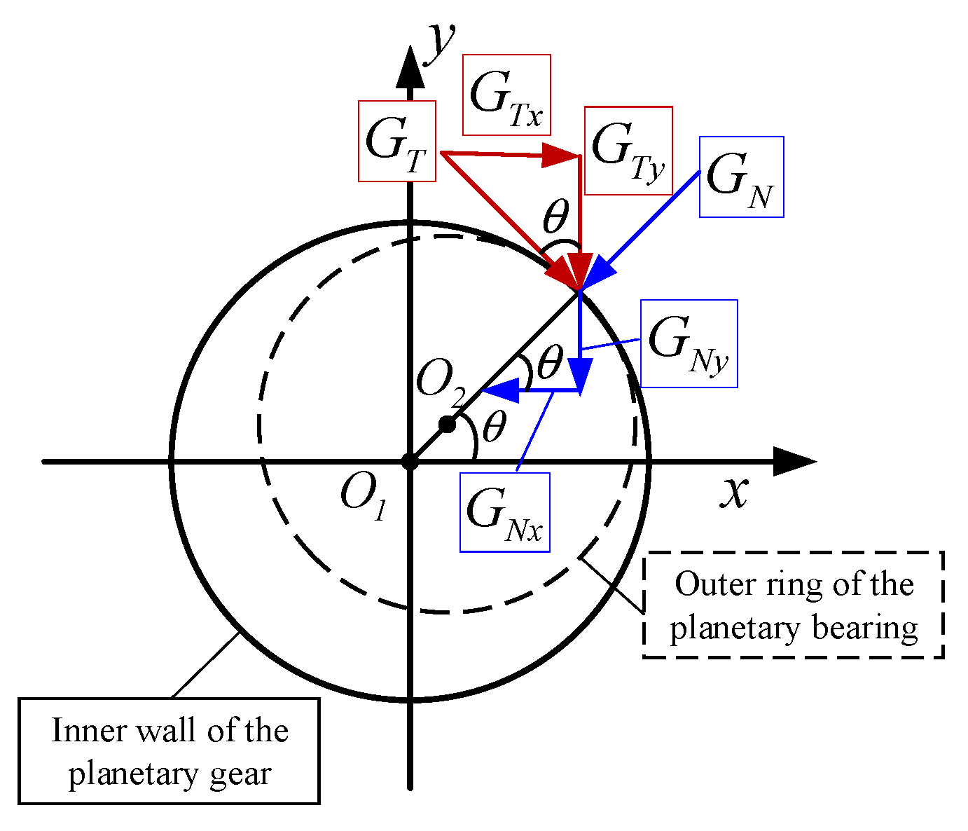
There will be relative sliding between the outer ring and the inner wall of the planetary gear when the outer ring looseness fault arises [,]. Figure 1 shows the stress state between the OR and the IWPG. The planetary bearing will be eccentric when the looseness fault arises. In Figure 1, O1 and O2 are the center of the planetary gear and the outer ring of the planetary bearing, respectively. Generally, O1 and O2 are coincident in the normal state. GN is the normal impact force, and GT is the tangential friction force. GNx, GNy, GTx, and GTy are component forces of GN and GT in the x and y directions, respectively. θ is the included angle between GN and the x-axis.
Figure 1.
Force analysis diagram between the OR of the planetary bearing and the IWPG [].
Then, the vibration displacement and velocity of the planetary bearing outer ring relative to the planetary gear in the x and y directions are illustrated in Equation (9) [].
The radial relative displacement r between the planetary bearing outer ring and planetary gear is proven in Equation (10) [].
The OR and the IWPG will rub against each other when the radial relative displacement r is larger than the fit clearance c. In general, the fit clearance c between OR and IWPG (Transition fit: H7/js6) is close to 1 × 10⁻⁶ m. The included angle θ can be stated in Equation (11) [].
Assuming the friction between the OR and the IWPG corresponds to Coulomb’s law of friction, the impact force and the friction direction of the IWPG relative to the OR are positive. Then, the normal impact force GN and its component forces, GNx and GNy, in the x and y directions are stated in Equation (12) [].
where kr is the radial stiffness of planetary gear. γ denotes the fault detection parameter.
Considering a friction coefficient fc between the OR and the IWPG, the tangential velocity of the OR (Δv) and the tangential friction force (GT) in relation to the planetary gear are shown in Equation (13), in which GTx and GTy are the component forces of GT in the x and y directions [].
It is worth noting that the GT is consistent with the direction of Δv. If Δv greater than zero, it means that the GT is the same as the positive direction, and vice versa.
In conclusion, Equation (14) can be used to express the non-linear force acting on the planetary bearing in the x and y directions when the outer ring looseness fault is present [].
2.4. Dynamic Modeling of Faulty Planetary Bearing
The lumped parameter method is used to construct the dynamic modeling of the planetary bearing. mor and mir are the mass of the planetary bearing outer ring and inner ring, respectively. The kinetic equation of the outer ring can be stated in Equation (15) [].
Bearing eccentricity for the inner ring will result from the outer ring looseness fault. Consequently, the dynamic equation of the inner ring can be stated as follows when imbalanced force is added in Equation (16) [].
3. Joint Modeling of Planetary Gear Train and Bearings
The planetary gearbox’s primary construction is depicted in Figure 2, which includes a schematic diagram of the transmission path, the primary parts (shown in the graph), and the coupling situation of each component. The conventional planetary gear train modeling generally simplifies the bearing as a rigid body, which is expressed in the dynamic model as the constant supporting stiffness. However, the planetary bearing outer ring looseness fault emerges in the planetary gear train, which will alter the supporting stiffness [,,]. Therefore, the bearing modeling is used to further enhance the planetary gear train model.
Figure 2.
Structure diagram of the planetary gearbox.
3.1. Joint Dynamic Modeling
Firstly, the translation-torsion hybrid model is utilized to establish the dynamic equation of the planetary gear train, which is composed of linear displacement of translational vibration and angular displacement of torsional vibration. The angular vibration displacement is transformed into linear displacement between the two gear teeth to ensure the consistency of the overall equation, which is stated in Equation (17) [].
Each component of the planetary gear train has the following subscripts: s, p, c, and r, which stand for the sun gear, the planetary gear, the carrier, and the ring gear, respectively. It is worth noting that N is the number of planetary gears (n = 1, 2, …, N). u, θ, and r indicate the equivalent linear vibration displacement in the torsional direction, the angular vibration displacement, and the equivalent radius, respectively.
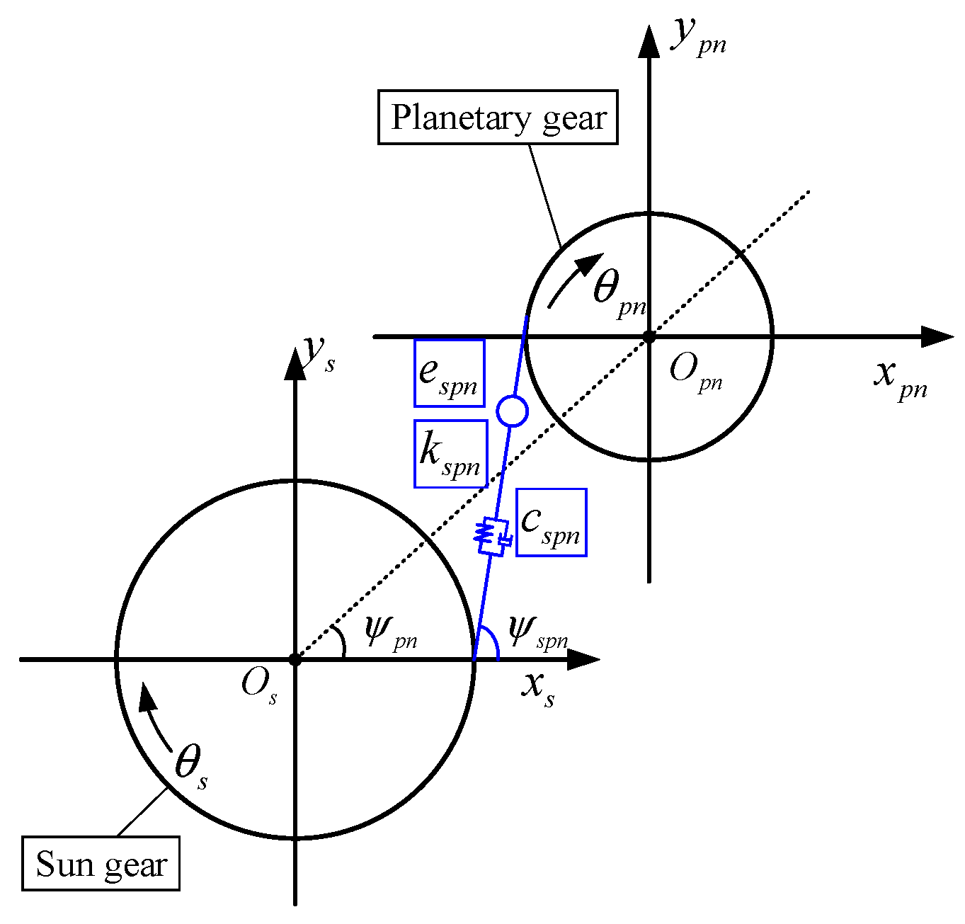
The meshing elastic deformation between different gears is often expressed by equivalent displacement. Figure 3 depicts the relative meshing connection of the sun gear with the planetary gear. Since the gear is regarded as an equivalent rigid body, the equivalent displacement between the sun gear and the planetary gear consists of four components: the projection of the vibration displacement in the x and y directions on the meshing line; the linear equivalent vibration displacement in the torsion direction; and the transmission error. The equivalent displacement δspn expression may be derived from the geometric connection in the illustration as in Equation (18) [].
where xs, xpn, ys, and ypn represent the vibration displacement of the sun gear and planetary gear in the x and y directions, respectively. espn(t) is the comprehensive error transfer function between the planetary gear and the sun gear. ψspn denotes the included angle of the meshing line (sun gear and planetary gears) between the x-axis and the sun gear in the global coordinate system. The formula [] can be deduced from the geometric relationship in Figure 3.
where α denotes the pressure angle.
Figure 3.
Meshing relationship diagram between the sun gear and the planetary gear [].
Similar to the preceding description, the equivalent displacement equation δrpn between the ring gear and planetary gear can be derived as shown in Equation (20) [].
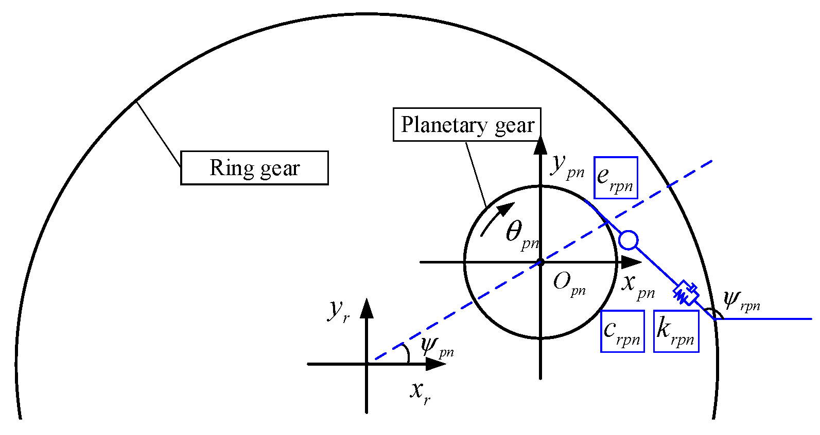
where xr and yr denote the vibration displacement of the ring gear in the x and y directions, respectively. erpn(t) is the comprehensive error transfer function between the planetary gear and the ring gear. ψrpn denotes the included angle of the meshing line (ring gear and planetary gears) between the x-axis and the sun gear in the global coordinate system. As shown in Equation (21), the formula [] can be deduced from the geometric relationship in Figure 4.
Then, the multi-degree-of-freedom spring-damping dynamic model can be constructed to depict the coupling relationship of each component in the planetary gear train. The specific processes are shown as follows:
- (1)
- Sun gear: The force analysis of the sun gear is proven as follows: the primary forces of the sun gear include the supporting force of the corresponding bearing and the meshing force between planetary gears and the sun gear. The dynamic model of the sun gear can be illustrated in Equation (22) [].
- (2)
- Ring gear: The force analysis of the ring gear can be illustrated as follows: The primary forces comprise the supporting force of the fixed housing and the meshing force between the planetary gears and the ring gear. The dynamic model of the ring gear is stated in Equation (24) [].
- (3)
- Planetary gears: The force analysis of the planetary gears can be stated as follows: The primary forces involve the meshing forces between the planetary gears, the sun gear, and the ring gear, as well as the supporting forces of the planetary bearings. The dynamic equation of the planetary gears in the normal state can be shown in Equation (26) [].
Figure 4.
Meshing relationship diagram between the ring gear and the planetary gear [].
The planetary bearing is modeled in Section 2. Then, kpnx and kpny can be further expanded using the first-order Taylor formula. kpn is used to deduce the computation process to replace kpnx, kpny, and kpnu for the simplified representation in Equation (28).
where k′pn(.) is the first-order derivative of kpn(.). If the planetary bearing is in the normal state, kpn is constant, and k′pn equals zero. If it is in the fault state, kpn is time-varying, and the variation degree of kpn depends on the failure degree. Therefore, the outer ring looseness fault of the planetary bearing can be integrated into the planetary gear train model. The time-varying kpn(t) can be stated in Equation (29).
where γn denotes the fault detection parameter of the nth planetary gear. Gfault is the resultant force of GN (normal impact force) and GT (tangential friction force) in the fault state. r represents the radial relative displacement between the planetary bearing outer ring and the planetary gear. The specific description of fault modeling can be found in Section 2.
Ffcpnx, Ffcpny, and Ffcpnu are utilized to stand for the interaction forces in the fault state.
Then, Equation (26) can be remodeled in Equation (31) for joint modeling with the outer ring looseness fault of the planetary bearing.
If γ equals zero, the planetary bearing is in the normal state, and Equation (31) degenerates to Equation (26). If γ is not equal to zero, this indicates that the planetary bearing has an outer ring looseness fault. Ffcpnx, Ffcpny, and Ffcpnu are used to remodel the fault state.
- (4)
- Planetary carrier: The force analysis of the planetary carrier can be illustrated as follows: the primary forces include the supporting force and the reaction force of the planetary gears. The dynamic model of the planetary carrier is expressed in Equation (32) [].
If the planetary bearing is in the outer ring looseness fault state, the interaction forces, Ffcpnx, Ffcpny, and Ffcpnu can be integrated into Equation (32). The joint dynamic model of the planetary carrier can be illustrated in Equation (33).
where mc, rc, and Jc denote the mass, the equivalent radius, and the moment of inertia of the planetary carrier, respectively. kcx, kcy, kcu, ccx, ccy, and ccu represent the supporting stiffness and damping in the x, y, and u directions, respectively.
3.2. Physical Parameters Modeling in Joint Model
The physical parameters, time-varying mesh stiffness (kspn and krpn), mesh damping (cspn and crpn), and the comprehensive error transfer functions (espn(t) and erpn(t)) in the joint model should be further stated in this section for the better simulated results.
3.2.1. Time-Varying Mesh Stiffness and Damping Modeling
This research mainly focuses on the simulation of the planetary bearing outer ring looseness fault. Therefore, the mesh stiffness is solved using the Fourier series expansion without detailed modeling. The specific expression is shown in Equation (34).
where kt is the mesh stiffness, denotes the average mesh stiffness, ωm represents the mesh frequency of gears, ψ0 stands for the initial phase of gears, and aj and bj are the Fourier expansion coefficients. Q is the series of Fourier expansion, q = 1, 2, …, Q. A decreased Q results in worse stiffness accuracy, whereas an increased Q leads to an excessively long computation duration. Thus, Q = 50 is selected for this research in order to balance computational efficiency and accuracy.
The mesh stiffness (kspn and krpn) of the joint model can be modeled in Equation (35).
Then, the mesh damping (cspn and crpn) can be deduced using the empirical formula, which is proven in Equation (36).
where ζ denotes the mesh damping coefficient. Generally, ζ = 0.03~0.08.
3.2.2. The Comprehensive Error Transfer Function
The term comprehensive error transfer function refers to the errors that are produced during the phases of manufacture and installation. These errors primarily include gear meshing errors, gear transmission errors, tooth pitch deviation errors, and tooth profile deviation errors. The dynamic excitation of the gear meshing process is caused by the tooth profile surface departing from the optimal tooth profile location. Within the transmission system, it is one of the primary types of internal excitation. The sinusoidal function is typically employed in the dynamic model of the transmission system to mimic the overall gear transmission error, and its mathematical expression is in Equation (37) [].
where e(t) is the comprehensive error transfer function, denotes the average transmission error, ea represents the amplitude of errors, and ωm stands for the mesh frequency.
Then, the comprehensive error transfer function between the sun gear, the ring gear and the planetary gear can be illustrated in Equation (38) [].
3.3. Transmission Path Simulation of the Signal in the Ring Gear
The transmission path effect of the ring gear can be defined as follows: the measured accelerometer is often installed on the surface of the ring gear, and the vibration produced by the planetary gear will progressively increase and then decrease as it gets closer to the sensor in the ring gear’s monitoring area. This phenomenon is stated as the transmission path effect [,,].
Then, the transmission path effect can be simulated using the Gaussian curve with adjustable weight (AWGC) for the more refined results to illustrate the failure mechanism. The AWGC can be noted in Equation (39).
where t is the input variable; in general, t is the time series. θ, μ, and η are the hyperplane parameters of the adjustable weight. θ is used to adjust the vertex of the curve, μ is utilized to determine the center position of the curve, and η is used to control the tightening degree of the curve. If the θ and η equal 1, and μ equals 0, the ΓAWGC denotes the normal Gaussian curve.
Then, the signal is weighted using the ΓAWGC to simulate the transmission path effect. The formula is depicted in Equation (40).
where C[.] is the operator to concatenate the simulated signal with the T periods. There are t points in a single period. ẍrw denotes the weighted acceleration signal in the x direction. The deduced process of the simulated signal in the y and u directions is similar to Equation (40).
4. Vibration Analysis of the Proposed Model
4.1. Results Analysis
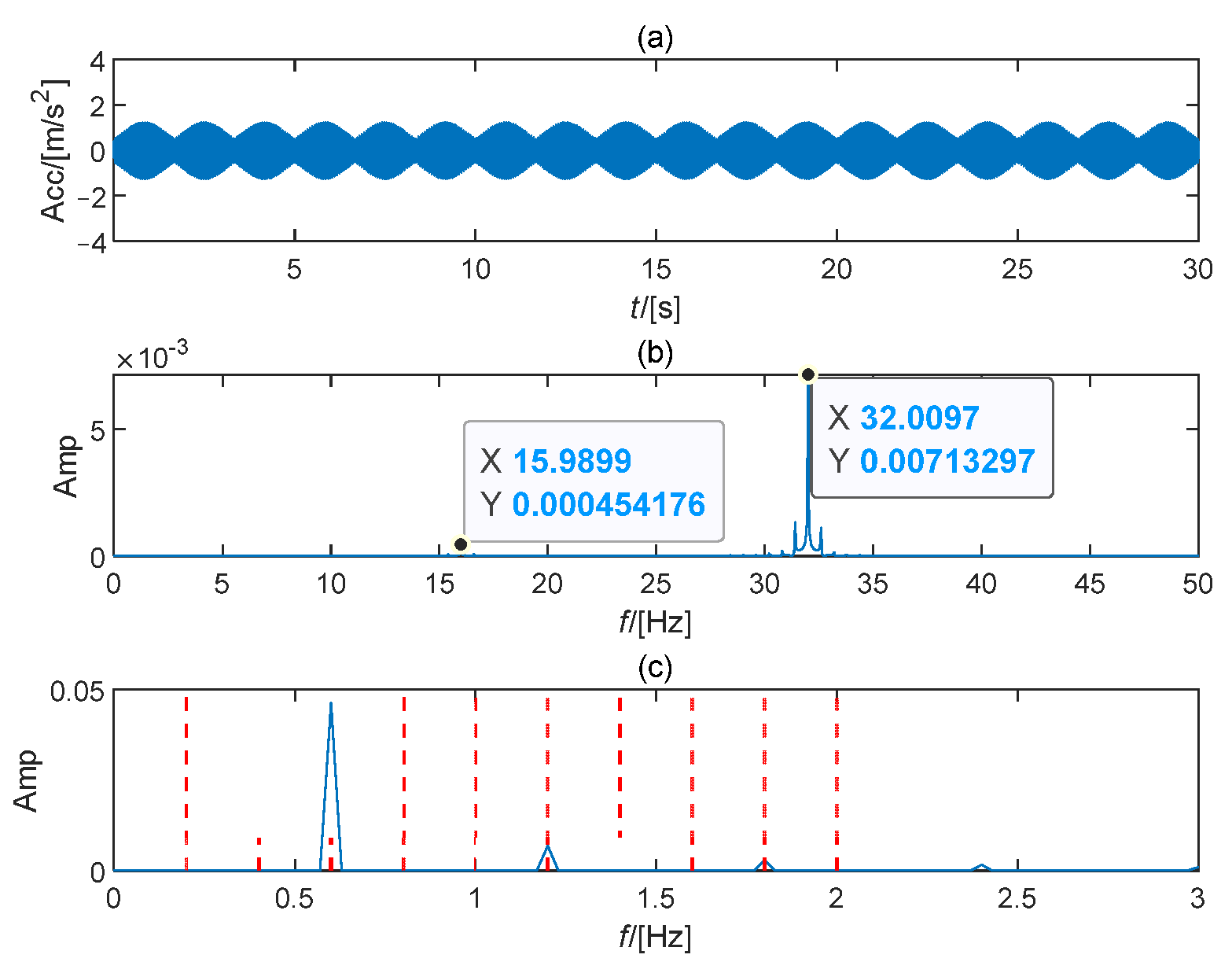
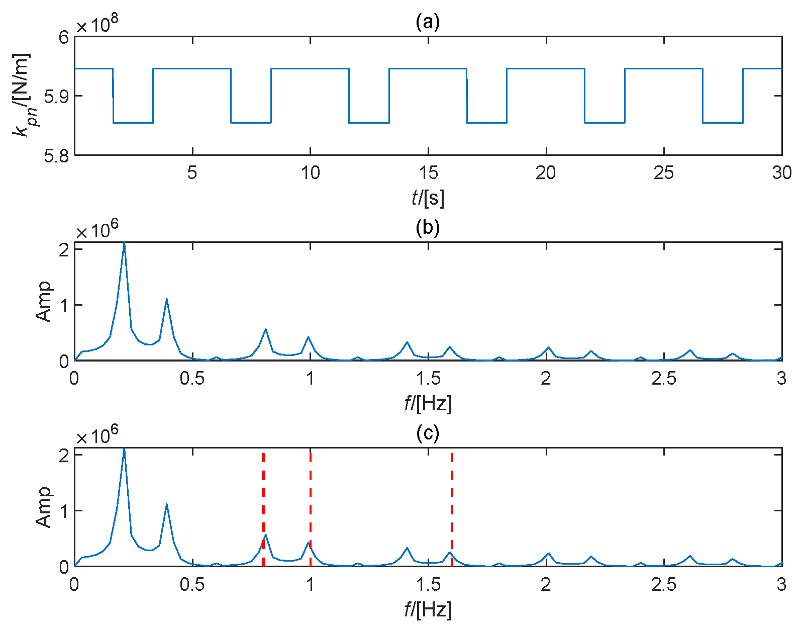
The proposed joint dynamic model is compiled using MATLAB 2023b with the ode15s solver. The simulation step size is 1/5120. The specific parameters are summarized in Appendix A. The simulated vibration signal in the x direction of the ring gear is utilized for analysis. Firstly, Figure 5a shows the simulated acceleration signal in the normal state without periodic impulses. Figure 5b states the meshing frequency of the planetary gear train and its harmonics (red dashed lines) in the frequency domain. In Figure 5c, the primary frequency is the triple rotating frequency, which is the characteristic frequency of the transmission path effect, and the fault frequency and its harmonics are not present in the envelope spectrum. Then, the planetary bearing outer ring looseness fault is simulated with ten percent degree growth. The definition of fault degree is the eccentric distance of the planetary bearing. The distance from no eccentricity to the furthest eccentricity is divided into ten equal parts, and the acceleration signal for each node is simulated for vibration analysis. In this study, the extreme eccentric distance is set to 10 mm. Then, the simulation node is situated at the eccentric distance of 0, 1, …, 9 mm, with the corresponding fault degree of 0%, 10%, …, 90%. Figure 6a depicts the simulated acceleration signal at the 40% fault degree, and the periodic amplitudes are enhanced in the time-domain waveform. In the frequency domain, the meshing frequency and its harmonics also behave consistently with the main components in Figure 6b. However, several modulation components arise around the meshing frequency. Figure 6c shows the fault frequency and its high-order harmonics (red dashed lines) emerge in the envelope spectrum. This phenomenon is consistent with the fault mechanism. After that, Figure 7a states the corresponding supporting stiffness of the planetary gear. The supporting stiffness is deduced with the fault period in the measured area that the failure planetary gear passes through the ring gear. Figure 7b,c show the main components are the fault characteristic and its harmonics (red dashed lines) in frequency and envelope spectrum. The fundamental reason is that the outer ring looseness fault of the planetary bearing causes the supporting stiffness to diminish as the planetary gear rotates. As a result, the vibration amplitude will increase during this period.
Figure 5.
Simulated signal in normal state: (a) Time waveform; (b) Frequency spectrum; (c) Envelope spectrum.
Figure 6.
Simulated signal in fault state: (a) Time waveform; (b) Frequency spectrum; (c) Envelope spectrum.
Figure 7.
Supporting stiffness in fault state: (a) Time waveform; (b) Frequency spectrum; (c) Envelope spectrum.
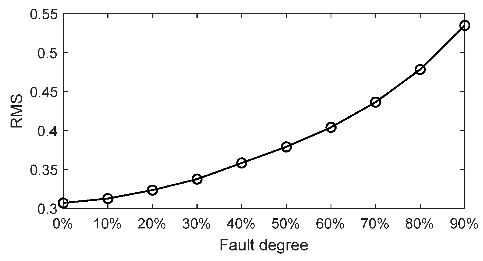
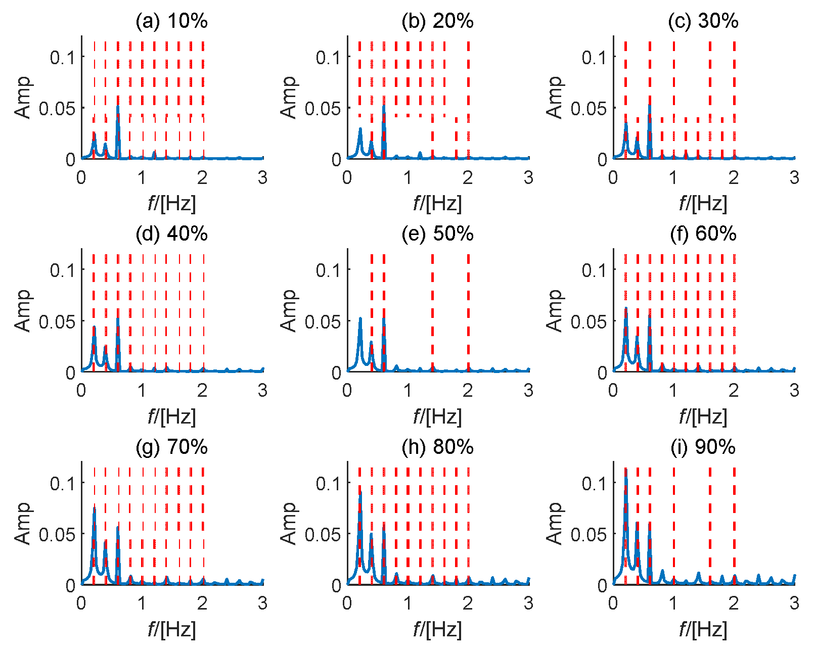
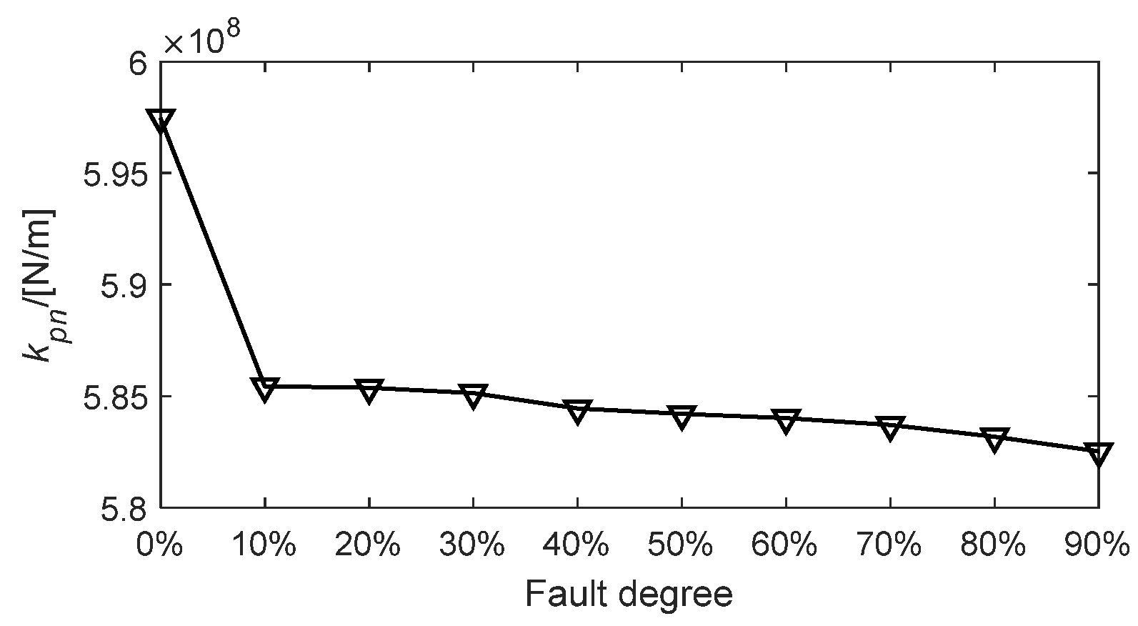
Figure 8 depicts the RMS values of the simulated acceleration signal in different fault degrees. The RMS of the signal increases nonlinearly with the development of the fault. Then, Figure 9 states the corresponding envelope spectra in different fault degrees (red dashed lines denote the harmonics of fault frequency). When the fault degree is relatively low (10~40%), the transmission path effect frequency features appear as the primary components in the signal; when the fault grows to more than 50%, the fault features in the signal show as the primary characteristic. Figure 10 shows the supporting stiffness in different fault degrees. The support stiffness rapidly diminishes as the fault progresses, which is also the primary reason for the increase in vibration.
Figure 8.
RMS value of the simulated acceleration signal in different fault degrees.
Figure 9.
Envelope spectra in different fault degrees.
Figure 10.
Supporting stiffness kpn in different fault degrees.
4.2. Comparison and Explanation of Simulation Effects
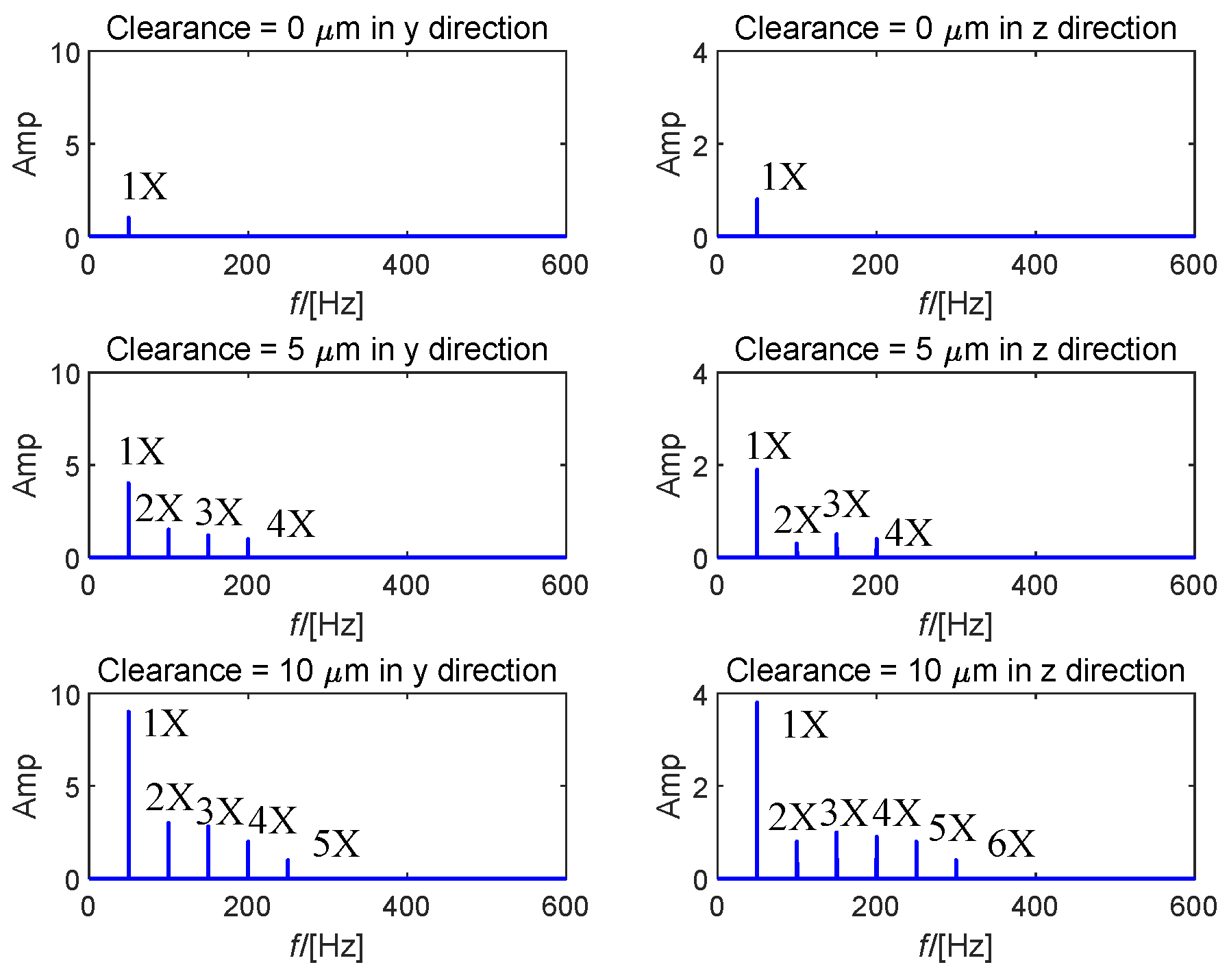
The results of the simulation in Section 4.1 are further investigated and analyzed in light of the conclusions of Refs. [,]. Figure 11 shows the simulated outcomes of rotor-bearing joint modeling in Ref. [] at various looseness clearances. The detailed modeling parameters can be found in Ref. []. Figure 11 illustrates that as the degree of loosening develops, the fault’s characteristic energy steadily increases, and the higher-order components become more prominent. This phenomenon is consistent with the simulation results of this study. As shown in Figure 12, Ref. [] is utilized to analyze the fault phenomena caused by generator bearing loosening of wind turbines. Periodic impulses in the time domain will result from a bearing loosening fault, and the corresponding envelope spectrum will display the fault characteristic frequency and its higher-order harmonics. This also confirms the effectiveness of the model conclusions proposed in this study.
Figure 11.
The spectra of simulated signal under different looseness degrees [].
Figure 12.
Results of nondriven-end generator bearing looseness []: (a) Time waveform; (b) Frequency spectrum; (c) Envelope spectrum.
4.3. On-Site Signal Verification
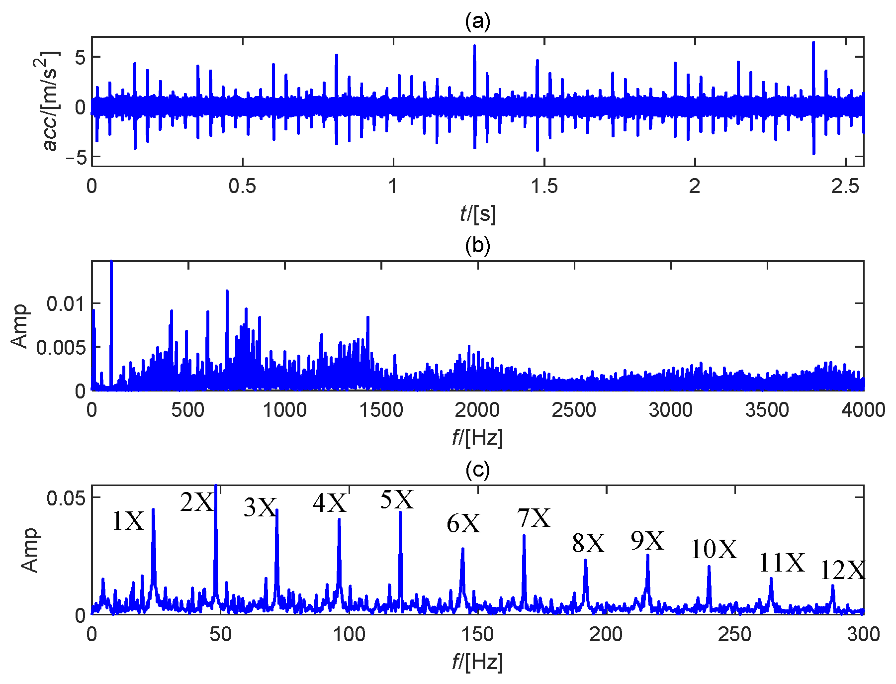
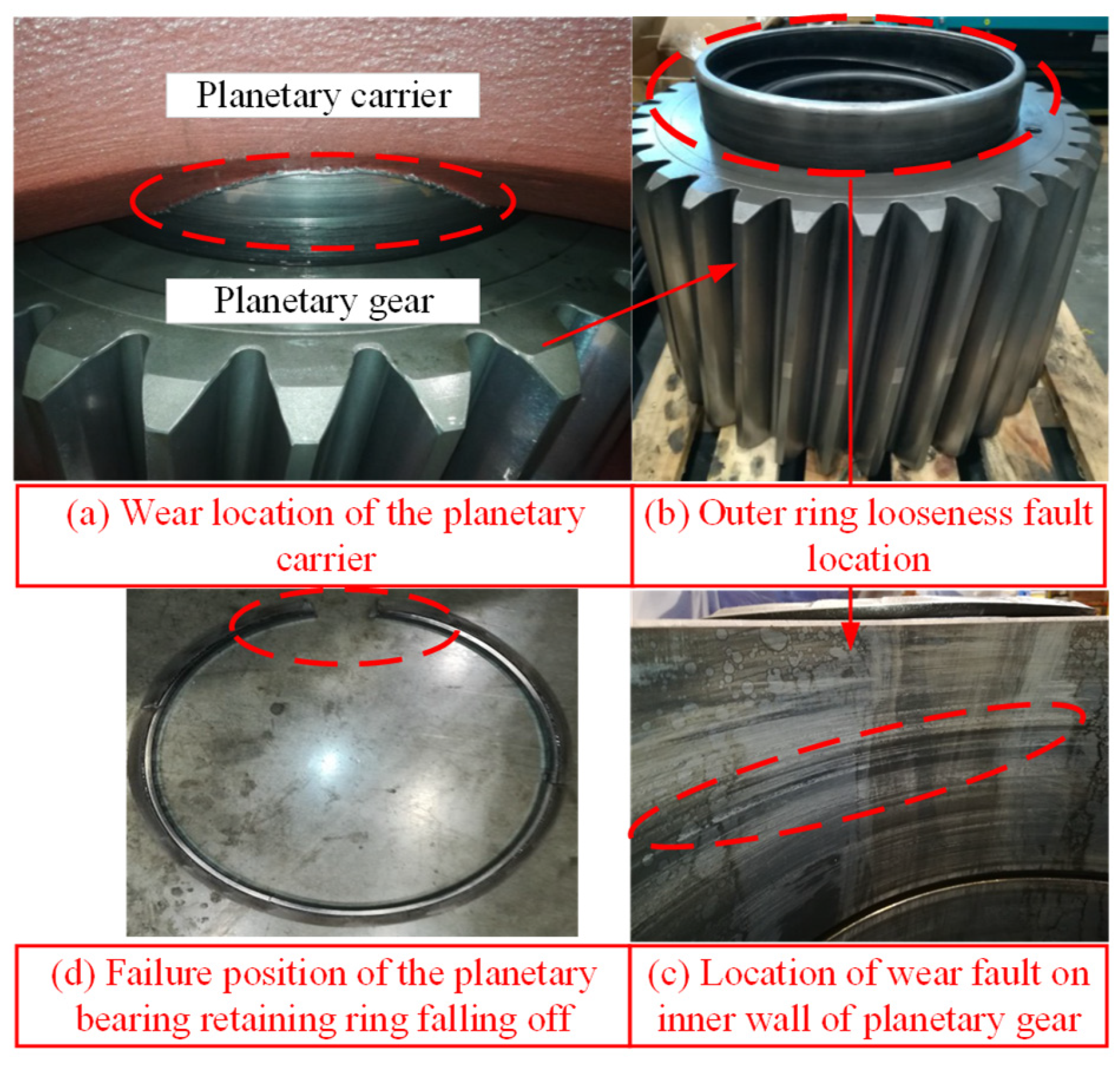
The aforementioned results serve to further validate the efficacy of the model. However, the accurate representation of fault frequency remains challenging, as the current modeling approach does not account for certain physiological effects inherent to the planetary stage (particularly those arising under low-speed operating conditions and the influence of complex transmission paths within the gear arrangement). Integrating the fault mechanism and signal simulation results, the on-site signal is further utilized to illustrate the correctness of the conclusion. The vibration acceleration data is sourced from a 2.2 MW double-fed wind turbine in a certain wind farm, and its measuring points are obtained from the surface of the internal ring gear. The specific structural parameters are concluded in Appendix A. Following the identification of a loosening fault in the wind turbine’s planetary bearing, a structural teardown was performed to diagnose the root cause. Figure 13 shows the disassembled diagram of the fault location. The primary reason for the looseness fault of the planetary bearing is that the retaining ring of the outer ring slips off. Figure 13a,b state the looseness fault location. Figure 13c depicts the wear fault location on the inner wall of the planetary gear. Figure 13d shows the falling retainer ring. Figure 14a states the measured acceleration signal in the ring gear. The periodic components are not prominent in the time domain. Figure 14b,c depict the corresponding frequency spectrum and envelope spectrum, respectively. In the frequency domain, the primary components are the meshing frequency of the planetary gear train and its harmonic with the modulation in fault frequency. The fault frequency and its harmonics (red dashed lines) are conspicuous in the envelope spectrum. It is worth noting that the characteristic frequency of the transmission path effect (triple rotating frequency) is also superimposed on the frequency, which is consistent with the fault mechanism and simulation results.
Figure 13.
Disassembled diagram of the fault location.
Figure 14.
On-site signal analysis: (a) Time waveform; (b) Frequency spectrum; (c) Envelope spectrum.
5. Conclusions and Discussion
A joint model of the wind turbine’s planetary gear train is constructed to demonstrate the failure process of the planetary bearing outer ring looseness fault. This study can be concluded as follows:
- (1)
- A new joint model was obtained, which differs from traditional dynamic modeling of bearing looseness. In this study, more detailed and practical modeling structures were considered, such as the power transmission between bearings and planetary gears and the influence of transmission paths when monitoring vibration data at acceleration measurement points.
- (2)
- Modeling in the Matlab environment showed consistency between simulation results and mechanism research. The simulated results reveal that this fault reduces the supporting stiffness of the corresponding planetary gear, resulting in an imbalance between the gears. The looseness fault characteristic can be represented as the rotating frequency and harmonics of the planetary carrier.
- (3)
- A comparison of the results of numerical modeling and a natural experiment showed a significant degree of similarity in the primary frequency characteristics, indicating the modeling’s efficacy and ability to approximate the theoretical signal of bearing looseness in complicated planetary structures.
Although this study has produced a somewhat realistic result for joint modeling, there are still some issues that need to be discussed, and additional potential directions for future research might be suggested.
- (A)
- Convergence analysis: From a qualitative standpoint, this research presents a joint model based on force analysis to follow the rules of dynamics, which is an essential requirement for convergence. From a quantitative standpoint, the simulation results of this study fit the prior mechanism derivation and are similar to the primary features of on-site signals, hence proving the model’s convergence.
- (B)
- Future prospects: This study primarily focuses on joint modeling of planetary gearboxes. Wind turbines, on the other hand, have a more complicated structure, with several excitation sources to consider, including the impact of main bearings, high-speed gearbox, and other components, as well as the influence of operating conditions such as speed, load, and temperature. Therefore, a more refined model can be discussed to be closer to the characteristic frequency of the entire wind turbine in the future.
Author Contributions
Conceptualization, C.Z.; methodology, D.F.; software, N.Z.; validation, N.Z. and X.M.; formal analysis, N.Z.; investigation, D.F.; resources, D.F.; data curation, X.M.; writing—original draft preparation, C.Z.; writing—review and editing, C.Z.; visualization, R.W.; supervision, C.Z.; project administration, R.W.; funding acquisition, R.W. All authors have read and agreed to the published version of the manuscript.
Funding
This research was funded by Innovation Foundation of China Electric Power Research Institute (CEPRI), grant number NY83-24-006.
Data Availability Statement
The original contributions presented in this study are included in the article. Further inquiries can be directed to the corresponding author.
Conflicts of Interest
All authors were employed by the China Electric Power Research Institute. The authors declare that the research was conducted in the absence of any commercial or financial relationships that could be construed as a potential conflict of interest.
Appendix A
Table A1.
The parameters description.
Table A1.
The parameters description.
| Parts | Parameters | Value |
|---|---|---|
| Sun gear | teeth number | 19 |
| mass | 1500 kg | |
| supporting stiffness | 2 × 10⁸ N/m | |
| supporting damping | 1 × 10⁵ | |
| Planetary carrier | mass | 3000 kg |
| supporting stiffness | 2 × 10⁸ N/m | |
| supporting damping | 1 × 10⁵ | |
| Ring gear | teeth number | 86 |
| mass | 4440 kg | |
| supporting stiffness | 2 × 10⁸ N/m | |
| supporting damping | 1 × 10⁵ | |
| Planetary gears | Number of planetary gear | 3 |
| teeth numbermodulus (ms = mr = mp) | 3345 mm | |
| mass | 2500 kg | |
| supporting stiffness | 5.9 × 10⁸ N/m | |
| supporting damping | 1 × 10⁶ | |
| average mesh stiffness (kspn = krpn) | 1 × 10¹⁰ N/m | |
| Planetary bearings | radius of inner ring | 255.1 mm |
| radius of outer ring | 340 mm | |
| width | 160 mm | |
| Number of rolling elements | 24 | |
| contact stiffness | 6 × 10⁶ N/m | |
| Simulated signal | Sampling frequency | 5120 Hz |
| Fault frequency | 0.2 Hz | |
| Sampling duration | 30 s | |
| On-site signal | Sampling frequency | 5120 Hz |
| Fault frequency | 0.2 Hz | |
| Sampling duration | 30 s |
References
- Stanojević, M.; Tomović, R.; Ivanović, L.; Stojanović, B. Critical Analysis of Design of Ravigneaux Planetary Gear Trains. Appl. Eng. Lett. 2022, 7, 32–44. [Google Scholar] [CrossRef]
- Vasić, M.; Blagojević, M.; Stojić, B.; Dizdar, S. Design and Performance Analysis of an In-Wheel Hub Reducer. Adv. Eng. Lett. 2022, 1, 115–125. [Google Scholar] [CrossRef]
- Wang, S.; Du, J.; Li, C.; Xia, S.; Jiang, S.; Sun, J. Crack Propagation Analysis of Slewing Bearings in Wind Turbines Applying a Modified Sub-Model Technology. Eng. Fail. Anal. 2023, 153, 107556. [Google Scholar] [CrossRef]
- Chen, Y.; Jin, X.; Yue, Y.; Wang, S.; Han, H.; Wen, M.; Wang, Q.; Cheng, P. Investigation on 3D Fatigue Crack Propagation in Pitch Bearing Raceway of Offshore Wind Turbines. Ocean. Eng. 2023, 269, 113524. [Google Scholar] [CrossRef]
- Yu, Y.; Guo, L.; Chen, Z.; Gao, H.; Shi, Z.; Zhang, G. Dynamics Modelling and Vibration Characteristics of Urban Rail Vehicle Axle-Box Bearings with the Cage Crack. Mech. Syst. Signal Process. 2023, 205, 110870. [Google Scholar] [CrossRef]
- Chen, R.; Zhao, B.; Xin, Q.; Niu, X.; Xie, Z.; Lu, X.; Zou, D. Analysis of Transient Lubrication and Wear Coupling Behaviors Considering Thermal Effect and Journal Misalignment for Main Bearings under Dynamic Load. Wear 2024, 554–555, 205478. [Google Scholar] [CrossRef]
- Lehmann, B.; Trompetter, P.; Guzmán, F.G.; Jacobs, G. Evaluation of Wear Models for the Wear Calculation of Journal Bearings for Planetary Gears in Wind Turbines. Lubricants 2023, 11, 364. [Google Scholar] [CrossRef]
- Chen, R.; Zhao, B.; He, T.; Tu, L.; Xie, Z.; Zhong, N.; Zou, D. Study on Coupling Transient Mixed Lubrication and Time-Varying Wear of Main Bearing in Actual Operation of Low-Speed Diesel Engine. Tribol. Int. 2024, 191, 109159. [Google Scholar] [CrossRef]
- Wang, F.; Ling, X.; Zhang, Z.; Dai, P.; Yan, S.; Wang, L. The Effect of Fit Clearance between Outer Race and Housing on Vibration Characteristics of a Cylindrical Roller Bearing with Localized Defects. Machines 2022, 10, 415. [Google Scholar] [CrossRef]
- Yang, Y.; Ouyang, H.; Yang, Y.; Cao, D.; Wang, K. Vibration Analysis of a Dual-Rotor-Bearing-Double Casing System with Pedestal Looseness and Multi-Stage Turbine Blade-Casing Rub. Mech. Syst. Signal Process. 2020, 143, 106845. [Google Scholar] [CrossRef]
- Yang, Y.; Yang, Y.; Cao, D.; Chen, G.; Jin, Y. Response Evaluation of Imbalance-Rub-Pedestal Looseness Coupling Fault on a Geometrically Nonlinear Rotor System. Mech. Syst. Signal Process. 2019, 118, 423–442. [Google Scholar] [CrossRef]
- Jafarian, M.J.; Nazarzadeh, J. A TDF Model in Induction Machines for Loose Bearing Diagnosis by Neutral Voltage. IEEE Trans. Ind. Electron. 2020, 67, 8155–8163. [Google Scholar] [CrossRef]
- Zhao, Y.; Zhu, Y.-P.; Lin, J.; Han, Q.; Liu, Y. Analysis of Nonlinear Vibrations and Health Assessment of a Bearing-Rotor with Rub-Impact Based on a Data-Driven Approach. J. Sound Vib. 2022, 534, 117068. [Google Scholar] [CrossRef]
- Wang, H.; Guan, X.; Chen, G.; Gong, J.; Yu, L.; Yuan, S.; Zhu, Z. Characteristics Analysis of Rotor-Rolling Bearing Coupled System with Fit Looseness Fault and Its Verification. J. Mech. Sci. Technol. 2019, 33, 29–40. [Google Scholar] [CrossRef]
- Nan, G.; Yao, J.; Chen, X.; Jiang, S. Coupling Dynamics of Pedestal Looseness and Impact-Rub for Rotor System with Nonlinear Support. Adv. Mech. Eng. 2024, 16, 16878132231222907. [Google Scholar] [CrossRef]
- Xu, H.; Wang, P.; Ma, H.; Yang, Y.; Li, X.; Luo, Z.; Han, Q.; Wen, B. Dynamic Behaviors and Contact Characteristics of Ball Bearings in a Multi-Supported Rotor System under the Effects of 3D Clearance Fit. Mech. Syst. Signal Process. 2023, 196, 110334. [Google Scholar] [CrossRef]
- Zeng, Q.; Liu, Y.; Du, W.; Jiang, L.; Yu, W. Dynamic Characteristic Analysis of a Gear-Rotor-Bearing Coupling System Considering Bearing Fit. Nonlinear Dyn. 2025, 113, 2131–2154. [Google Scholar] [CrossRef]
- Liu, P.; Wang, L.; Ma, F.; Zheng, D.; Wu, J.; Li, Z. Influence of Assembly Clearance on Vibration Characteristics of Angular Contact Ball Bearings in the Thermal Environment. Tribol. Int. 2023, 181, 108317. [Google Scholar] [CrossRef]
- Yin, J.; Meng, X.; Cheng, S.; Fang, X.; Fan, X. Tribo-dynamics modeling and analysis of planetary gear bearing systems in wind turbines considering sun-planetary-ring helical gear mesh and elastic deformation effects. Tribol. Int. 2024, 200, 110059. [Google Scholar] [CrossRef]
- Xu, H.; Ren, H.; Qin, D. Dynamic characteristics of the planetary gear system with rolling bearing. Multibody Syst. Dyn. 2023, 59, 171–191. [Google Scholar] [CrossRef]
- Wang, P.; Xu, H.; Ma, H.; Han, H.; Yang, Y. Effects of three types of bearing misalignments on dynamic characteristics of planetary gear set-rotor system. Mech. Syst. Signal Process. 2022, 169, 108736. [Google Scholar] [CrossRef]
- Zhang, B.; Teng, W.; Tang, S.; Peng, D.; Fang, Q.; Ma, Z. Sparsity-assisted energy decoupling model for fault detection of planetary ring gear in wind turbines. Mech. Syst. Signal Process. 2025, 238, 113235. [Google Scholar] [CrossRef]
- Nie, Y.; Lu, H.; Chen, X.; Li, G.; Zhang, C.; Wang, L.; Li, F. Interpreting vibration characteristics of planetary gearboxes for condition monitoring based on a novel transfer path effect model. Nonlinear Dyn. 2025, 113, 9351–9371. [Google Scholar] [CrossRef]
- Jing, H.; Zhen, D.; Feng, G.; Liang, X.; Zhang, H.; Gu, F. Improved Transfer Path Effect Model Considering Frequency Attenuation for Planetary Gear Train with Sun Gear Fault. Shock. Vib. 2025, 1, 1559627. [Google Scholar] [CrossRef]
- Teng, W.; Ding, X.; Tang, S.; Xu, J.; Shi, B.; Liu, Y. Vibration Analysis for Fault Detection of Wind Turbine Drivetrains-A Comprehensive Investigation. Sensors 2021, 21, 1686. [Google Scholar] [CrossRef]
- Zhou, P.; Du, M.; Chen, S.; He, Q.; Peng, Z.; Zhang, W. Study on Intra-Wave Frequency Modulation Phenomenon in Detection of Rub-Impact Fault. Mech. Syst. Signal Process. 2019, 122, 342–363. [Google Scholar] [CrossRef]
- Harris, T.A. Essential Concepts of Bearing Technology; Taylor & Francis: Abingdon, UK, 2006; pp. 199–212. [Google Scholar]
- Xue, S.; Wang, C.; Howard, I.; Lian, P.; Chen, G.; Wang, Y.; Yan, Y.; Xu, Q.; Shi, Y.; Jia, Y.; et al. The diagnostic analysis of the fault coupling effects in planet bearing. Eng. Fail. Anal. 2019, 108, 104266. [Google Scholar] [CrossRef]
- Chen, G.; Qu, M. Modeling and Analysis of Fit Clearance between Rolling Bearing Outer Ring and Housing. J. Sound Vib. 2019, 438, 419–440. [Google Scholar] [CrossRef]
- Cao, H.; Shi, F.; Li, Y.; Li, B.; Chen, X. Vibration and Stability Analysis of Rotor-Bearing-Pedestal System Due to Clearance Fit. Mech. Syst. Signal Process. 2019, 133, 106275. [Google Scholar] [CrossRef]
- Mao, Y.; Wang, L.; Zhang, C. Influence of Ring Deformation on the Dynamic Characteristics of a Roller Bearing in Clearance Fit with Housing. Int. J. Mech. Sci. 2018, 138–139, 122–130. [Google Scholar] [CrossRef]
- Wei, J.; Zhang, A.; Qin, D.; Lim, T.C.; Shu, R.; Lin, X.; Meng, F. A Coupling Dynamics Analysis Method for a Multistage Planetary Gear System. Mech. Mach. Theory 2017, 110, 27–49. [Google Scholar] [CrossRef]
- Liu, J.; Li, X.; Xia, M. A Dynamic Model for the Planetary Bearings in a Double Planetary Gear Set. Mech. Syst. Signal Process. 2023, 194, 110257. [Google Scholar] [CrossRef]
- Liang, X. Dynamics Based Vibration Signal Modeling and Fault Detection of Planetary Gearboxes; University of Alberta: Edmonton, AB, Canada, 2016. [Google Scholar]
- Liu, J.; Pang, R.; Ding, S.; Li, X. Vibration Analysis of a Planetary Gear with the Flexible Ring and Planet Bearing Fault. Measurement 2020, 165, 108100. [Google Scholar] [CrossRef]
- Kong, Y.; Wang, T.; Chu, F. Meshing Frequency Modulation Assisted Empirical Wavelet Transform for Fault Diagnosis of Wind Turbine Planetary Ring Gear. Renew. Energy 2019, 132, 1373–1388. [Google Scholar] [CrossRef]
- Wang, T.; Chu, F.; Han, Q. Fault Diagnosis for Wind Turbine Planetary Ring Gear via a Meshing Resonance Based Filtering Algorithm. ISA Trans. 2017, 67, 173–182. [Google Scholar] [CrossRef]
Disclaimer/Publisher’s Note: The statements, opinions and data contained in all publications are solely those of the individual author(s) and contributor(s) and not of MDPI and/or the editor(s). MDPI and/or the editor(s) disclaim responsibility for any injury to people or property resulting from any ideas, methods, instructions or products referred to in the content. |
© 2025 by the authors. Licensee MDPI, Basel, Switzerland. This article is an open access article distributed under the terms and conditions of the Creative Commons Attribution (CC BY) license (https://creativecommons.org/licenses/by/4.0/).