Abstract
Under overmodulation conditions, the capacitor voltages of half-bridge and full-bridge submodules in hybrid modular multilevel converters (MMCs) may become unbalanced. This imbalance not only gives rise to overvoltage stress on submodule capacitors, jeopardizing equipment safety, but also degrades power quality and may even trigger operational instability. To address this issue, this paper proposes a minimum second harmonic circulating current injection method based on Bayesian Adaptive Direct Search (BADS) within the overall framework of model predictive control for MMCs. The method efficiently solves complex objective functions by alternately performing local Bayesian optimization and global grid search. Optimal second harmonic injection values under different modulation indices are obtained through offline computation and curve fitting. This approach achieves dynamic capacitor voltage balancing across a wide modulation range while minimizing operational losses caused by harmonic currents.
1. Introduction
The Modular Multilevel Converter, owing to its high modularity, excellent scalability, and flexible control capability, has been widely adopted in high-voltage, high-power applications such as flexible DC transmission [1,2]. However, conventional half-bridge MMCs are inherently constrained by their topology: they cannot effectively block DC-side fault currents nor support overmodulation operations under step-down voltage conditions during extreme operating scenarios [3,4,5], thereby limiting system reliability and operational flexibility. In contrast, the hybrid MMC, composed of both half-bridge submodules (HBSMs) and full-bridge submodules (FBSMs), leverages the ability of FBSMs to generate negative voltage levels [6,7]. This enables not only fault isolation but also decouples the voltage limitation imposed by conventional topologies, thereby supporting overmodulation operations [8].
Nevertheless, under conditions such as sudden DC voltage drops, the differing output capabilities of the submodules can lead to dynamic capacitor voltage imbalance, which threatens stable system operation [9,10]. Specifically, HBSMs can only output positive voltage levels, whereas FBSMs can generate both positive and negative levels. Therefore, achieving capacitor voltage balancing for hybrid MMCs under overmodulation conditions has become a critical challenge. Existing control strategies can generally be categorized into two main types:
The first category achieves capacitor voltage balancing by adjusting the topology or submodule ratio. A hybrid MMC structure based on balancing branches is proposed in [11], which can effectively balance the voltage and reduce power loss under overmodulation conditions, but at the cost of increased component count and circuit complexity. A non-symmetrical hybrid MMC is designed in [12], where HBSMs and FBSMs are placed in different bridge arms to structurally avoid energy imbalance; however, its adaptability is insufficient under extreme conditions, especially during pole-to-ground fault ride-through. In [13], the voltage deviation between HBSMs and FBSMs is compensated by increasing the proportion of FBSMs, and when the FBSM ratio exceeds 75%, all HBSMs are bypassed under DC voltage drop conditions; nevertheless, this significantly increases system cost and power loss, requiring a trade-off between performance and economy.
The second category is based on energy analysis theory, injecting specific currents into the arm currents to extend the negative voltage interval. Voltage balancing can be achieved by injecting reactive current on the AC side, but this comes at the expense of the power factor [14]. A fundamental frequency reactive circulating current is introduced to avoid this issue [15]; however, it introduces low-order harmonics. In [16], a method injecting a second harmonic circulating current based on a capacitor voltage fluctuation model is proposed. This method utilizes Fourier decomposition to extract the second-order component of the FBSM voltage for energy balancing. Nevertheless, it suffers from computational complexity, and its accuracy is susceptible to the submodule (SM) control strategy. This problem is considered in [17], and a method calculating optimal harmonic parameters by establishing an instantaneous arm power model is proposed. However, all the above methods rely on complex energy fluctuation analysis to calculate precise circulating current references.
The submodule energy balancing mechanism is analyzed in [18], and a negative-sequence circulating current injection method that linearly correlates the second harmonic current with the AC output is proposed. This significantly reduces computational complexity. However, its effectiveness is limited to a narrow modulation index range, restricting its applicability. A dynamic regulation mechanism for a second harmonic circulating current based on voltage feedback is proposed in [19], but it requires linearized modeling for selecting appropriate PI controller parameters. Optimized strategies for different overmodulation conditions, hybrid ratios (HBSM to FBSM ratio), and power factor angles are designed in [20]. However, the parameter optimization calculation involved is overly complex. Notably, a capacitor voltage balancing method based on enhanced phase-shifted modulation and model predictive control (MPC) is proposed in [21]. It achieves flexible SM insertion through a consolidated cost function and redundancy strategy, making it suitable for a wide modulation index range. Its main drawback is high computational complexity, limiting its engineering practicality.
In summary, although existing capacitor voltage balancing strategies for overmodulation operation each offer certain advantages, they are all subject to significant limitations. The first category—methods based on modifying the hardware topology or submodule configuration—aims to inherently mitigate energy imbalance by structural changes, such as incorporating auxiliary balancing circuits, adopting asymmetric arm designs, or increasing the proportion of full-bridge submodules. However, these approaches inevitably lead to higher hardware costs, increased system complexity, and greater conduction losses. The second category, which employs current injection at the control level, avoids hardware modifications but still faces several challenges: model-based analytical methods require complex energy calculations and are sensitive to parameter variations, and simplified techniques (e.g., linear correlation or PI control) are often limited to narrow modulation ranges or require extensive tuning.
To address the aforementioned limitations, this paper proposes a secondary harmonic injection-based voltage balancing strategy optimized via the Bayesian Adaptive Direct Search (BADS) algorithm. The proposed approach offers three distinct advantages over conventional methods:
- Structural Preservation: This avoids topology modifications and full-bridge submodule ratio increases, significantly reducing operational losses while maintaining effective voltage balancing.
- Model Independence: This eliminates the need for precise analytical modeling by efficiently handling complex optimization problems through alternating local Bayesian optimization and global grid search.
- Broad-Range Applicability: This establishes a mathematical mapping between secondary harmonic injection and modulation index via curve fitting, enabling dynamic capacitor voltage balancing across a wide modulation range.
The remainder of this paper is organized as follows: Section 2 analyzes the causes of capacitor voltage imbalance in hybrid MMCs and the conditions for simplifying its control. Section 3 presents a secondary harmonic injection voltage balancing control strategy based on BADS optimization. Section 4 provides simulation results and analysis for the hybrid MMC. Finally, Section 5 concludes this paper.
2. Analysis of Capacitor Voltage Imbalance
As shown in Figure 1, the hybrid MMC consists of three identical phase units (denoted by j, where ). Each phase is composed of an upper and a lower arm (denoted by q, where ; p represents the upper arm and n represents the lower arm). Each arm contains N submodules, including HBSMs and FBSMs. In the diagram, and represent the DC-side voltage and current, respectively; and denote the AC-side output voltage and current of the MMC; and are the voltages of the upper and lower arms, while and are the corresponding arm currents. and represent the output-side filter resistance and inductance, respectively, denotes the arm inductance, is the submodule capacitance, and is the rated voltage of each submodule.
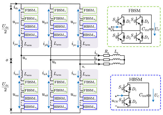
Figure 1.
The topology diagram of hybrid MMC.
Firstly, we define the expressions for the AC-side voltage and current of the system as follows:
where and are the amplitudes of the AC-side output voltage and current, respectively, and is the power factor angle.
To facilitate the analysis of system characteristics, the AC voltage modulation index m is defined as follows:
As shown in the circuit of Figure 1, the arm output voltage and current are given by the following:
where denotes the DC component of the arm current.
Under normal steady-state operation with modulation index , the arm voltage remains entirely positive. Submodule charging/discharging is solely governed by the arm current: submodules charge when and discharge otherwise. Both HBSMs and FBSMs participate in sorting and switching operations. When , Equation (3) shows , causing the arm voltage to alternate between positive and negative values. During negative intervals, HBSMs cannot generate negative voltage levels. Thus, this function is entirely handled by FBSMs, while all HBSMs are bypassed.
Figure 2 presents waveforms of the upper arm voltage, arm current, and capacitor voltages for both HBSMs and FBSMs over one fundamental period, where and denote the zero-crossing points of the arm voltage; and represent the zero-crossing points of the arm current; and and indicate the intersection points between the arm voltage and the maximum output voltage of the FBSMs.
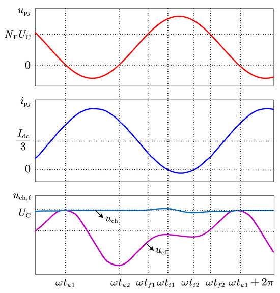
Figure 2.
Schematic diagram of FBSM and HBSM capacitors’ charging and discharging processes within a fundamental period.
Taking as the analysis starting point, the fundamental period is divided into six characteristic intervals. A thorough analysis of the dynamic fluctuation characteristics of submodule capacitor voltages within each interval is then conducted. At the initial time, the capacitor voltages of HBSMs and FBSMs are equal, as shown below:
During Stage 1 (), the arm-end voltage is negative while the arm current is positive. Since HBSMs cannot output negative voltage, they are fully bypassed, and only FBSMs contribute to the voltage output. As current flows through the FBSMs, their capacitors discharge and voltage decreases, while the HBSM capacitor voltage remains unchanged due to bypassing [15,22].
In Stage 2 (), both arm voltage and current are positive. FBSMs, having lower capacitor voltage from the previous stage, are prioritized for charging, while HBSMs remain bypassed due to their higher voltage.
In Stage 3 (), the arm maintains positive voltage and current. FBSMs are still prioritized for charging due to their lower voltage, but HBSMs are also inserted to supplement voltage beyond the FBSMs’ output capability.
Stage 4 () features positive arm voltage and negative current—this is the only interval within one fundamental cycle when HBSMs can discharge. HBSMs are prioritized for energy release due to their higher voltage, while FBSMs supply the remaining voltage.
In Stage 5 (), with both voltage and current positive again, FBSMs are charged first due to their lower voltage. HBSMs are inserted if the required voltage exceeds the capacity of FBSMs.
Stage 6 () continues with positive voltage and current. All inserted submodules are charged, and since HBSMs have higher capacitor voltage, FBSMs are prioritized. As in Stage 2, HBSMs remain bypassed.
In summary, the net changes in capacitor voltages for HBSMs and FBSMs over a complete fundamental period can be expressed as follows:
The total arm energy of the MMC remains balanced over one cycle, with a net accumulation of zero [23]. If voltage accumulation occurs in the HBSMs (), the voltage of the FBSMs must correspondingly decrease (), resulting in a significant deviation between the capacitor voltages of the two submodule types (as shown in Figure 3).
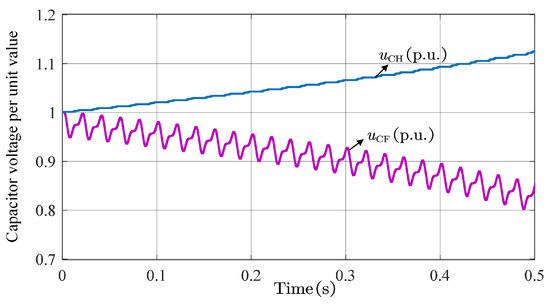
Figure 3.
Schematic diagram of capacitor voltage imbalance phenomenon.
Therefore, achieving submodule capacitor voltage balancing requires the following conditions to be satisfied:
Specifically, expanding yields the following:
As observed from Equation (8), the calculation involves complex integral operations, which increase the difficulty of implementing the control strategy. Therefore, it is necessary to optimize the control approach by leveraging the system’s characteristics. Under overmodulation conditions, depending on the modulation index, the capacitor voltage behavior can be categorized into three states, as shown in Figure 4: stable balance state, critical balance state, and imbalance state [20].
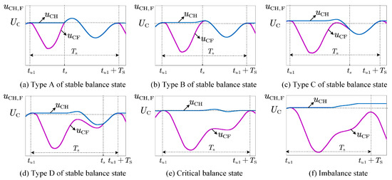
Figure 4.
Schematic diagram of capacitor voltage state classification.
Analysis of different states shows that in both stable and critical balance conditions, HBSM and FBSM capacitor voltages converge by the end of each fundamental cycle. Thus, the universal condition for voltage balancing can be further simplified as follows:
where denotes the fundamental period.
3. Overall Control of Hybrid MMC
To ensure the reliable operation of the hybrid MMC, three core control objectives must be achieved: (1) accurate tracking of the AC phase current; (2) suppression of harmonic components in the circulating current; and (3) dynamic balancing of submodule capacitor voltages [24]. The first two objectives are achieved using finite control set model predictive control (FCS-MPC), while the third is addressed under overmodulation by injecting second harmonic components.
3.1. Output Current Tracking and Circulating Current Suppression Based on FCS-MPC
From the single-phase equivalent circuit in Figure 5a, the voltage–current relationship on the AC side is given by the following:
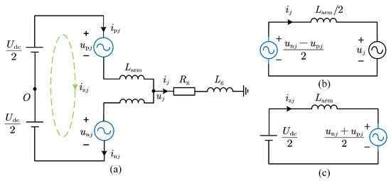
Figure 5.
(a) Single-phase equivalent circuit of hybrid MMC. (b) AC equivalent circuit. (c) DC equivalent circuit.
According to Kirchhoff’s Voltage Law, the relationship between the upper and lower arms of phase j can be derived from Figure 5a, as follows:
Meanwhile, the upper and lower arm currents are related to the circulating current as follows:
Based on Equations (10)–(14), the continuous-time mathematical model of the AC-side current and circulating current components for phase j is given by the following:
Let . Based on the forward Euler method and Equations (14) and (15), the discrete-time dynamic expressions can be derived as follows:
where and denote the number of inserted submodules in the upper and lower arms, respectively.
To eliminate weighting factor, a cascade-sequence MPC method is adopted [25], with capacitor voltage balancing handled separately. Cost functions for current tracking and circulating current suppression, alongside submodule constraints, are formulated as follows:
where N denotes the total number of submodules per arm, represents the output current reference value at the next time step, and indicates the circulating current reference value at the next time step. The latter is composed of a DC component and an optimal second harmonic component generated by the BADS algorithm, as follows:
It is worth noting that, to reduce computational burden, the event-triggered (ET) mechanism is applied to the predictive control of the output current in this paper. The system state feedback and input signals are updated only when the error norm exceeds the triggering threshold.
To design the ET triggering boundary for MMC, the output current mathematical model needs to be reformulated into a standard state-space representation. Equation (15) is thus rewritten as follows:
Define , , , and . Then, the above equation can be expressed as follows:
The state error is defined as follows:
where denotes the activation instant of the next event trigger. When , the ET control strategy updates the state variable from to and transmits it to the FCS-MPC scheme.
Based on the derivation of the event-triggering boundary that ensures asymptotic stability of the system in [26], the system error should satisfy the following condition:
where denotes the regulation coefficient, represents the maximum output voltage, and indicates the fixed sampling time step set by the ET control scheme.
By substituting matrices A and B from the state-space representation of the hybrid MMC’s output current canonical form into Equation (25) and selecting an appropriate regulation coefficient , an established error bound for event-triggered MPC (ET-MPC) is derived. During the time interval , the system maintains the control input computed at , while the norm of the state error remains below the event-triggered threshold. State feedback and input signals are updated only when the error norm exceeds this triggering boundary.
3.2. Voltage Balancing Control Strategy Based on BADS-Optimized Second Harmonic Injection
As shown in Equations (2) and (3), when , the arm current may exhibit unipolar characteristics. Since HBSM can only charge when the current is positive and discharge when the current is negative, prolonged unipolar operation leads to continuous charging or discharging, causing the capacitor voltage to deviate from its rated value and affecting system stability. An appropriately injected second harmonic circulating current can transform the unipolar arm current into a bipolar one, thereby optimizing current distribution and achieving dynamic balance between charging and discharging [27]. However, excessive harmonics can also be detrimental to the system [28]. This section focuses on optimizing the amplitude and phase of the second harmonic to keep capacitor voltage balanced while minimizing harmonic losses.
Based on the simplified capacitor voltage balancing condition in by Equation (9), this section constructs an objective function using the voltage feedback of HBSMs and FBSMs at the end of a fundamental cycle. The BADS algorithm is then employed to obtain the minimum second harmonic reference satisfying this condition, following three main steps.
3.2.1. Voltage Sampling
First, the endpoint of each fundamental period is identified. At this instant, the capacitor voltages of FBSMs and HBSMs are sampled, and their voltage difference is calculated. This process is performed for every arm of the hybrid MMC. Ultimately, the maximum voltage difference across all six arms is selected as the control signal, expressed as follows:
3.2.2. Obtaining the Optimal Second Harmonic Reference Amplitude Using BADS Algorithm
BADS is a hybrid optimization algorithm that combines Bayesian optimization (BO) with Mesh Adaptive Direct Search (MADS) [29,30,31]. It is well-suited for problems where the objective function’s gradient is unavailable or unreliable. Based on derivative-free MADS, BADS iteratively tests candidate points on a mesh around the current solution, with two phases: search and poll. In the search phase, BADS incorporates the BO algorithm to find the minimum of the objective function within a limited search space.
Firstly, the objective function for optimizing the second harmonic reference value is defined as follows:
In the equation, is a weighting factor that balances between and , while is a penalty factor controlling the growth rate of the exponential penalty term. When is large, the exponential term grows rapidly to ensure quick convergence. When , the penalty term approaches zero, focusing the optimization on minimizing .
Then, a local surrogate model of the objective function is constructed using Gaussian processes, and the acquisition function (such as the GP lower confidence bound) guides the selection of the next evaluation point [32], as shown in the following equation:
where denotes the historical mean, represents the posterior standard deviation, is the confidence parameter, and is a tunable hyperparameter.
If no improvement is found in the search stage, the algorithm proceeds to the polling stage, where candidate points are systematically generated on the mesh to enhance global exploration, ensuring convergence to a local optimum even when the surrogate model fails. The MADS mesh size is dynamically adjusted: it expands after success to speed up search and contracts after failure to improve resolution.
When the mesh size or the number of iterations (where K is the preset maximum iteration count), the BADS optimization process terminates, yielding the optimal solution.
BADS achieves efficient optimization of complex objective functions by alternately performing local Bayesian optimization and global grid search. When the GP model is accurate, the search phase rapidly identifies local optima; when the GP model is inaccurate, the polling phase provides a robust global search mechanism.
The BADS algorithm is applied to the optimization problem of the second harmonic reference value in this paper, and the pseudocode is shown in Algorithm 1.
| Algorithm 1 Bayesian Adaptive Direct Search (BADS) for optimal second harmonic injection |
| Input: Objective function , initial guess , lower bound , upper bound |
| Output: Optimal second harmonic current amplitude |
|
3.2.3. Determining the Phase of the Second Harmonic Reference Value
After obtaining the optimal amplitude of the second harmonic component, its phase must also be determined. Specifically, the phase should be configured to synchronize the negative peak of the injected circulating current with the negative peak of the arm current waveform. This synchronization achieves maximum extension of the arm current’s negative half-cycle, as a prolonged negative interval directly enhances capacitor voltage balancing performance. Therefore, the phase should be selected to ensure that the troughs of the injected circulating current and the arm current occur simultaneously, as shown in the following equation:
where denotes the amplitude of the second harmonic circulating current (SHCC) reference for phase j (), represents the phase angle of the second harmonic circulating current reference, and indicates the phase angle of the AC output current.
After obtaining the second harmonic reference, it is superimposed with the DC component to form the circulating current reference and integrated into the control system. As illustrated in Figure 6, the overall control architecture integrates this reference into the system. For AC output current tracking, an event-triggered MPC is employed, where system states are sampled and optimized only when the error exceeds the threshold. An initial set of submodule numbers and minimizing is selected. These are then perturbed by ±1 and 0 to form a candidate set, from which the optimal values and minimizing are determined via rolling optimization, enabling circulating current regulation. Finally, capacitor voltage balancing is achieved using a sorting algorithm, and the optimal control vector is output.
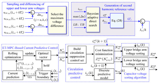
Figure 6.
Control strategy schematic diagram for capacitor voltage balancing in hybrid MMC via BADS-based second harmonic injection.
4. Results and Analysis
To validate the aforementioned analysis of capacitor voltage imbalance and the effectiveness of the proposed method, a hybrid MMC simulation model with a 1:1 ratio of full-bridge to half-bridge submodules was implemented in MATLAB/Simulink 2018b.This ratio was chosen to balance the requirements for submodule capacitor voltage balancing, DC short-circuit fault ride-through, DC-side fault clearance, and converter station construction cost [10,15]. The simulation parameters are specified in Table 1. In subsequent simulations, the system operates at unity power factor with constant AC-side voltage. The transmitted active power varies proportionally with the DC-side voltage, thus maintaining a constant DC-side current. The modulation index is adjusted by regulating the DC-side voltage.

Table 1.
Simulation parameters of hybrid MMC system.
4.1. Iterative Analysis of BADS
To validate the effectiveness of the Bayesian Adaptive Direct Search (BADS) control algorithm, this study takes the process of generating the optimal second harmonic component at a modulation index of as an example. The performance of the algorithm in terms of dynamic adjustment and global convergence is systematically analyzed. Figure 7 illustrates the evolution of the objective function over 45 iterations with respect to the second harmonic current .
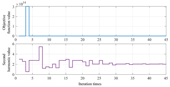
Figure 7.
The iterative optimization process of second harmonic generation based on BADS.
Simulation results show that the BADS algorithm initially expands the search range (corresponding to a significant increase in the second harmonic current) to rapidly reduce the objective function. When the objective function value exhibits minor variations, the algorithm switches to a local refinement search mode and gradually converges to the optimal solution. Specifically, as shown in Figure 8a, the objective function exhibits a clear minimum within the range . The final iteration result confirms that for a modulation index of , the optimal second harmonic current is , yielding a stabilized objective value of 2.2342. This dynamic adjustment mechanism highlights the algorithm’s ability to adaptively balance exploration and exploitation.
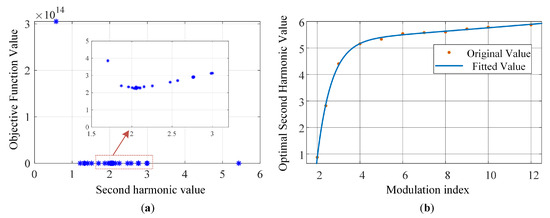
Figure 8.
Iteration process and function fitting. (a) Variation in objective function value with second harmonic component. (b) Fitting curve of the optimal second harmonic function.
To construct a generalizable optimization model, this paper further extends the modulation index to and applies the BADS algorithm to obtain a discrete set of optimal solutions under 11 typical step-down operating conditions. Figure 8b presents the regression analysis results using the exponential fitting toolbox, where orange dots represent the simulation data, while the blue curve corresponds to the fitted data. The specific fitting function is given as follows:
This model uses a dual-exponential structure to capture both the low-frequency modulation and high-frequency attenuation characteristics. The coefficient of determination is , and the root mean square error is , indicating high prediction accuracy. Further analysis reveals that the first term, , dominates the asymptotic growth for , reflecting the need for enhanced second harmonic injection under high modulation to compensate for submodule voltage fluctuations. The second term, , decays rapidly to zero, correcting nonlinear deviations in the low-modulation region.
Conventional online methods must solve complex optimization problems or compute integrals within every control cycle, leading to high computational load. In contrast, the proposed offline BADS method can obtain the optimal second harmonic value through adaptive search, providing a theoretical basis for real-time harmonic optimization of MMC systems under various operating conditions. During online control, only a simple function evaluation and table lookup is required, with fixed and minimal computational overhead, thereby significantly reducing the online computational complexity of the system.
4.2. Simulation Verification of Voltage Balancing Improvement Based on Second Harmonic Injection
To validate the capacitor voltage balancing mechanism of the hybrid MMC under DC-side step-down operating conditions, this section conducts simulations to investigate the impact of the modulation index m on submodule voltage balance. The effectiveness of the proposed solution is further verified by integrating the second harmonic optimization strategy.
Figure 9 presents the system dynamic response waveforms under four different DC voltage levels (1200 V, 1000 V, 800 V, and 600 V), including DC current, transmitted power, and the time-domain characteristics of the AC output current. The results show that as the DC voltage decreases from 1200 V to 600 V (corresponding to a modulation index increase from to ), the transmitted power and AC output current decrease linearly, while the DC current remains constant, consistent with the initial parameter settings.
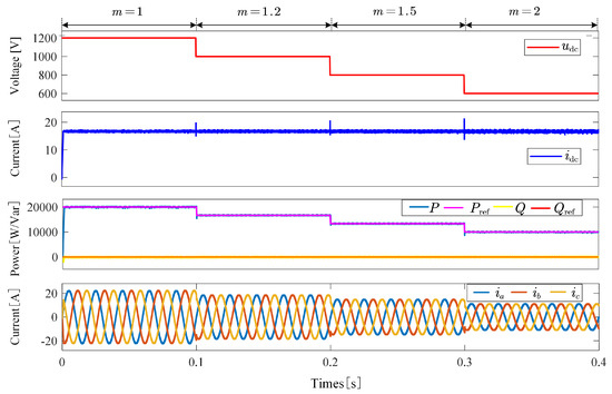
Figure 9.
System dynamic response waveforms under different modulation indices during DC-side step-down operation.
Figure 10 illustrates the dynamic response waveforms of arm voltage and current and submodule capacitor voltages under step-down operating conditions. The influence of the modulation index on capacitor voltage balancing is summarized as follows:
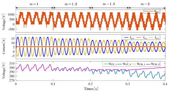
Figure 10.
Dynamic response waveforms of arm voltage, current, and submodule capacitor voltages during DC-side step-down operation.
When , the capacitor voltage waveforms of the FBSMs and HBSMs completely overlap. The system operates in a non-overmodulation mode, and the capacitor voltages remain balanced.
When , negative voltage intervals appear in the arm voltage, during which FBSMs output negative levels to sustain system operation, while HBSMs are bypassed. At this stage, the capacitor voltage waveforms of HBSMs and FBSMs partially diverge but still exhibit overlapping regions, indicating that although the system has entered overmodulation, the capacitor voltages are still balanced.
When , the arm current lacks negative intervals, preventing HBSMs from discharging and leading to energy accumulation and a noticeable increase in capacitor voltage. Meanwhile, FBSM voltages decrease due to self-balancing mechanisms of energy exchange in the arms. Eventually, this results in diverging capacitor voltages. This phenomenon indicates that when the modulation index exceeds a certain threshold, the voltage balancing capability of the hybrid MMC becomes significantly constrained.
To address the issue of capacitor voltage imbalance under overmodulation conditions, the DC voltage is reduced to 600 V at (corresponding to a modulation index ), and the optimal second harmonic component is injected using the BADS algorithm. Figure 11 illustrates the dynamic response of the system following the optimal second harmonic injection. A comparison with the response under the same modulation index in Figure 10 reveals that, in the absence of harmonic injection, the arm current comprises only DC and fundamental components, resulting in a clear divergence in capacitor voltages. Upon injection of the optimal second harmonic component, a small second harmonic is introduced into the arm current, creating negative intervals that effectively enable discharge in the HBSMs. This adjustment facilitates a near-critical balance of capacitor voltages and simultaneously reduces the losses associated with second harmonic circulating currents.
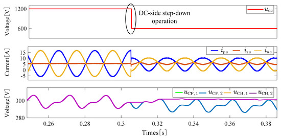
Figure 11.
Critical balance state of capacitor voltages after injecting the second harmonic () when the DC voltage drops to 0.5 p.u.
Further simulation analysis, as shown in Figure 12, demonstrates that while injecting a second harmonic magnitude greater than the optimal value can still achieve voltage balancing, it leads to a marked increase in current distortion. This, in turn, exacerbates harmonic losses and imposes higher electrical stress on the power semiconductor devices, thereby underscoring the importance of precise harmonic optimization.
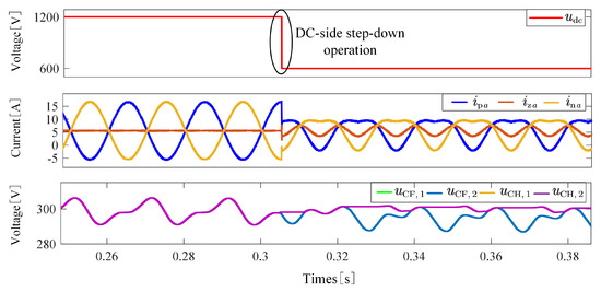
Figure 12.
Stable balance state of capacitor voltages after injecting the second harmonic () when the DC voltage drops to 0.5 p.u.
A comparative analysis of three operational scenarios—no injection, proposed BADS-optimized injection, and harmonic over-injection—clearly demonstrates the efficacy of the proposed strategy. As evidenced by Figure 10, Figure 11 and Figure 12, the BADS-optimized injection uniquely achieves an optimal compromise: it ensures stable capacitor voltage balancing while avoiding the significant current distortion inherent to over-injection scenarios. This highlights the critical importance of precise harmonic optimization for maintaining both stability and power quality.
Based on the above analysis, the following key conclusions can be drawn:
- Demarcation between critical and stable balance: At the optimal second harmonic amplitude, the system reaches a critical balance state (Figure 11), characterized by controllable voltage fluctuation and minimal loss. Exceeding this threshold leads to a stable balance (Figure 12), albeit at the cost of reduced efficiency and reliability.
- Optimization capability of BADS: The proposed BADS-based second harmonic optimization strategy exhibits strong global search capability, effectively avoiding local minima typical of conventional trial-and-error methods, and offers a robust approach for parameter tuning under complex operating conditions.
- Engineering trade-offs: In practice, the second harmonic injection should be adaptively adjusted according to system requirements for efficiency, reliability, and harmonic compliance, with fine-tuning recommended within the range of .
5. Conclusions
To achieve capacitor voltage balancing while simultaneously suppressing circulating current amplitude to reduce system losses, this paper proposes a voltage balancing control strategy based on BADS through second harmonic current injection. First, the mechanism of capacitor voltage imbalance in hybrid MMC is analyzed, and the fundamental control conditions required for voltage balancing are derived. Based on this analysis, the BADS algorithm is employed to obtain the optimal second harmonic injection values under various modulation indices. These discrete optimization results are further fitted into a mathematical function, establishing a mapping relationship between the modulation index and the second harmonic current, thereby enabling dynamic voltage balancing over a wide modulation range.
Compared with conventional methods, the proposed strategy offers the following advantages: (1) it does not rely on precise analytical modeling and efficiently searches for the global optimum through adaptive exploration; (2) it requires no changes to the converter topology or an increased proportion of FBSMs, thus maintaining voltage balancing while significantly reducing circulating current losses; (3) it supports a wider range of modulation indices, demonstrating strong engineering applicability. Simulation results validate the effectiveness and superiority of the proposed strategy in mitigating capacitor voltage imbalance in hybrid MMCs. To further substantiate its practical value, future work will include a quantitative analysis of operational losses and a systematic assessment of the computational burden across different control schemes.
Author Contributions
Conceptualization, Y.F. and Y.L.; methodology, Y.F. and S.S.; software, Y.F. and S.S.; validation, Y.F.; formal analysis, Y.F. and F.L.; investigation, J.G. and F.L.; resources, Y.L.; data curation, J.G.; writing—original draft, Y.F.; writing—review and editing, Y.L.; visualization, J.G.; supervision, F.L.; project administration, F.L.; funding acquisition, S.S. All authors have read and agreed to the published version of the manuscript.
Funding
This research was funded by the General Program of the National Natural Science Foundation of China under grant No. 52307213 and Guangdong Basic and Applied Basic Research Foundation under grant No. 2025A1515010115.
Data Availability Statement
The original contributions presented in the study are included in the article; further inquiries can be directed to the corresponding author.
Conflicts of Interest
Author Ying Fang was employed by the company State Grid Anhui Electric Power Co., Ltd. Chuzhou Power Supply Company. Author Jinlong Gu was employed by the company State Power Investment Corporation Green Energy Co., Ltd. Author Shuo Shi was employed by the company State Grid Shandong Electric Power Research Institute. The remaining authors declare that the research was conducted in the absence of any commercial or financial relationships that could be construed as a potential conflict of interest.
References
- Priya, M.; Ponnambalam, P.; Muralikumar, K. Modular-Multilevel Converter Topologies and Applications—A Review. IET Power Electron. 2019, 12, 170–183. [Google Scholar] [CrossRef]
- Perez, M.A.; Ceballos, S.; Konstantinou, G.; Pou, J.; Aguilera, R.P. Modular Multilevel Converters: Recent Achievements and Challenges. IEEE Open J. Ind. Electron. Soc. 2021, 2, 224–239. [Google Scholar] [CrossRef]
- Zhao, X.; Ding, J.; Xu, J.; Yuan, J. Hybrid MMC with Low Voltage Operations and DC Fault Ride-through Capabilities Based on Auxiliary Full-bridge Converter. CSEE J. Power Energy Syst. 2022, 8, 864–871. [Google Scholar]
- Hu, X.; Zhang, J.; Xu, S.; Jiang, Y. Investigation of a New Modular Multilevel Converter With DC Fault Blocking Capability. IEEE Trans. Ind. Appl. 2019, 55, 552–562. [Google Scholar] [CrossRef]
- Sakib, M.N.; Azad, S.P.; Kazerani, M. A Critical Review of Modular Multilevel Converter Configurations and Submodule Topologies from DC Fault Blocking and Ride-Through Capabilities Viewpoints for HVDC Applications. Energies 2022, 15, 4176. [Google Scholar] [CrossRef]
- Zhang, J.; Zhao, C. The Research of SM Topology With DC Fault Tolerance in MMC-HVDC. IEEE Trans. Power Deliv. 2015, 30, 1561–1568. [Google Scholar] [CrossRef]
- Zeng, R.; Xu, L.; Yao, L.; Williams, B.W. Design and Operation of a Hybrid Modular Multilevel Converter. IEEE Trans. Power Electron. 2015, 30, 1137–1146. [Google Scholar] [CrossRef]
- Xu, J.; Zhao, X.; Jing, H.; Liang, J.; Zhao, C. DC Fault Current Clearance at the Source Side of HVDC Grid Using Hybrid MMC. IEEE Trans. Power Deliv. 2020, 35, 140–149. [Google Scholar] [CrossRef]
- Lin, L.; Lin, Y.; Xu, C.; Chen, Y. Comprehensive Analysis of Capacitor Voltage Fluctuation and Capacitance Design for Submodules in Hybrid Modular Multilevel Converter with Boosted Modulation Index. IEEE J. Emerg. Sel. Top. Power Electron. 2018, 7, 2369–2383. [Google Scholar] [CrossRef]
- Li, M.; Dong, N.; Chang, X.; Yang, H.; Zhao, R. Analysis and Suppression of Capacitor Voltage Ripple for Hybrid MMCs Under Boosted AC Voltage Conditions. IEEE J. Emerg. Sel. Top. Power Electron. 2023, 11, 3775–3787. [Google Scholar] [CrossRef]
- Zhang, Y.; Zhang, J.; Deng, F.; Xu, Z.; Zhao, J. Hybrid Modular Multilevel Converter With Self-Balancing Structure. IEEE Trans. Ind. Appl. 2021, 57, 5039–5051. [Google Scholar] [CrossRef]
- Jung, J.J.; Cui, S.; Lee, J.H.; Sul, S.K. A New Topology of Multilevel VSC Converter for a Hybrid HVDC Transmission System. IEEE Trans. Power Electron. 2017, 32, 4199–4209. [Google Scholar] [CrossRef]
- Lin, W.; Jovcic, D.; Nguefeu, S.; Saad, H. Full-Bridge MMC Converter Optimal Design to HVDC Operational Requirements. IEEE Trans. Power Deliv. 2016, 31, 1342–1350. [Google Scholar] [CrossRef]
- Xiang, W.; Lin, W.; Xu, L.; Wen, J. Enhanced Independent Pole Control of Hybrid MMC-HVdc System. IEEE Trans. Power Deliv. 2018, 33, 861–872. [Google Scholar] [CrossRef]
- Lu, M.; Hu, J.; Zeng, R.; Li, W.; Lin, L. Imbalance Mechanism and Balanced Control of Capacitor Voltage for a Hybrid Modular Multilevel Converter. IEEE Trans. Power Electron. 2018, 33, 5686–5696. [Google Scholar] [CrossRef]
- Dong, Y.; Tang, J.; Yang, H.; Li, W.; He, X. Capacitor Voltage Balance Control of Hybrid Modular Multilevel Converters with Second- Order Circulating Current Injection. IEEE J. Emerg. Sel. Top. Power Electron. 2019, 7, 157–167. [Google Scholar] [CrossRef]
- Xu, J.; Deng, W.; Gao, C.; Lu, F.; Liang, J.; Zhao, C.; Li, G. Dual Harmonic Injection for Reducing the Submodule Capacitor Voltage Ripples of Hybrid MMC. IEEE J. Emerg. Sel. Top. Power Electron. 2020, 9, 3622–3633. [Google Scholar] [CrossRef]
- Hu, P.; Teodorescu, R.; Guerrero, J.M. Negative-Sequence Second-Order Circulating Current Injection for Hybrid MMC under Over-Modulation Conditions. IEEE J. Emerg. Sel. Top. Power Electron. 2020, 8, 2508–2519. [Google Scholar] [CrossRef]
- Chang, X.; Li, M.; Dong, N.; Yang, H.; Zhao, R. Comprehensive Analysis and Optimal Control for Capacitor Voltage Fluctuation Reduction in Hybrid MMCs under Different Over-Modulation Conditions. IEEE Trans. Power Deliv. 2024, 39, 2704–2714. [Google Scholar] [CrossRef]
- Zhang, Y.; Zhang, J.; Deng, F.; Din, Z. Voltage Balancing Control of Hybrid MMC under Over-Modulation Situations with Optimal Circulating Current Injection. Int. J. Electr. Power Energy Syst. 2022, 140, 108053. [Google Scholar] [CrossRef]
- Hashemi-Zadeh, A.; Ahmadi, S.; Neyshabouri, Y.; Asadi, E.; Iman-Eini, H.; Liserre, M. An Enhanced Model Predictive Capacitor Voltage Control of Hybrid Modular Multilevel Converters Under Overmodulation Circumstances. IEEE Trans. Power Electron. 2024, 39, 7130–7143. [Google Scholar] [CrossRef]
- Lee, J.H.; Jung, J.J.; Sul, S.K. Balancing of Submodule Capacitor Voltage of Hybrid Modular Multilevel Converter Under DC-Bus Voltage Variation of HVDC System. IEEE Trans. Power Electron. 2019, 34, 10458–10470. [Google Scholar] [CrossRef]
- Jia, G.; Chen, M.; Tang, S.; Zhang, C.; Zhao, B. A Modular Multilevel Converter With Active Power Filter for Submodule Capacitor Voltage Ripples and Power Losses Reduction. IEEE Trans. Power Electron. 2020, 35, 11401–11417. [Google Scholar] [CrossRef]
- Du, S.; Dekka, A.; Wu, B.; Zargari, N. Modular Multilevel Converters: Analysis, Control, and Applications; John Wiley & Sons: Hoboken, NJ, USA, 2017. [Google Scholar]
- Moon, J.W.; Gwon, J.S.; Park, J.W.; Kang, D.W.; Kim, J.M. Model Predictive Control With a Reduced Number of Considered States in a Modular Multilevel Converter for HVDC System. IEEE Trans. Power Deliv. 2015, 30, 608–617. [Google Scholar] [CrossRef]
- Wang, B.; Huang, J.; Wen, C.; Rodriguez, J.; Garcia, C.; Gooi, H.B.; Zeng, Z. Event-Triggered Model Predictive Control for Power Converters. IEEE Trans. Ind. Electron. 2020, 68, 715–720. [Google Scholar] [CrossRef]
- Li, H.; Wang, Q.; Wu, Q.; Xiao, L.; Li, J. Capacitor Voltage Balancing Method for Hybrid Modular Multilevel Converters Based on Second-Harmonic Voltage Injection. J. Power Electron. 2024, 24, 553–564. [Google Scholar] [CrossRef]
- Shan, P.; Sun, Y.; Song, Y.; Zhang, F.; Li, Y.; Sun, K. Adaptive Parameter Tuning and Virtual Impedance Injection Control for Coupled Harmonic Mitigation of Photovoltaic Converter. IEEE Trans. Power Electron. 2025, 40, 162–175. [Google Scholar] [CrossRef]
- Acerbi, L.; Ma, W.J. Practical Bayesian Optimization for Model Fitting with Bayesian Adaptive Direct Search. In Proceedings of the Advances in Neural Information Processing Systems, Long Beach, CA, USA, 4–9 December 2017; Curran Associates, Inc.: San Francisco, CA, USA, 2017. [Google Scholar]
- Wang, X.; Jin, Y.; Schmitt, S.; Olhofer, M. Recent Advances in Bayesian Optimization. ACM Comput. Surv. 2023, 55, 1–36. [Google Scholar] [CrossRef]
- Audet, C.; Le Digabel, S.; Tribes, C. Dynamic Scaling in the Mesh Adaptive Direct Search Algorithm for Blackbox Optimization. Optim. Eng. 2016, 17, 333–358. [Google Scholar] [CrossRef]
- Srinivas, N.; Krause, A.; Kakade, S.M.; Seeger, M. Gaussian Process Optimization in the Bandit Setting: No Regret and Experimental Design. arXiv 2009, arXiv:0912.3995. [Google Scholar]
Disclaimer/Publisher’s Note: The statements, opinions and data contained in all publications are solely those of the individual author(s) and contributor(s) and not of MDPI and/or the editor(s). MDPI and/or the editor(s) disclaim responsibility for any injury to people or property resulting from any ideas, methods, instructions or products referred to in the content. |
© 2025 by the authors. Licensee MDPI, Basel, Switzerland. This article is an open access article distributed under the terms and conditions of the Creative Commons Attribution (CC BY) license (https://creativecommons.org/licenses/by/4.0/).