Article

Research on the Suppression Method of Low-Order Harmonic Currents for Active Power Filters Using Quasi-Proportional Resonance Control

1
School of Electrical Engineering and Automation, Hefei University of Technology, Hefei 230009, China
2
Anhui Onesky Power Quality Technology Co., Ltd., Hefei 230088, China
*
Author to whom correspondence should be addressed.
Energies 2025, 18(21), 5697; https://doi.org/10.3390/en18215697
Submission received: 2 September 2025 / Revised: 26 September 2025 / Accepted: 21 October 2025 / Published: 30 October 2025
(This article belongs to the Section F: Electrical Engineering)

Abstract

Aiming at the significant challenges faced by active power filters (APFs) in suppressing low-order harmonic currents (such as second and fourth), this paper proposes a rarefaction suppression method based on quasi-proportional resonance (QPR) control. Firstly, the harmonic mathematical model of APFs in a synchronous, rotating coordinate system is established to reveal the inherent defects of traditional proportional–integral (PI) control in low-order harmonic suppression. Theoretical analysis shows that although the proportional resonant (PR) controller can achieve zero-steady-state-error tracking of specific frequency harmonics, its narrow bandwidth and low robustness may easily lead to system oscillation. Therefore, the QPR control strategy is introduced. By superimposing a low-pass filter with an adjustable cut-off frequency on the resonant link, the bandwidth is significantly broadened and the anti-frequency disturbance ability of the system is enhanced. In addition, the stability of QPR control parameters is analyzed. Finally, the verification based on the experimental platform demonstrates that the proposed method reduces the total harmonic distortion (THD) of the 380 V bus current from 82.18% to 3.45%, and the low-order harmonic current suppression performance is significantly better than the traditional scheme. This research provides an effective solution for the synergistic suppression of low-order harmonic currents.

1. Introduction

With the wide application of power electronic equipment in industrial and civil fields, the problem of harmonic pollution in the power grid is becoming increasingly serious. Low-order harmonics (especially the second and fourth harmonics) tend to cause grid resonance, equipment overheating, and metering errors due to their frequency close to the fundamental wave, energy concentration, and difficulty to filter out, which has become the key challenge of power quality management [1,2,3]. The active power filter (APF) is the core device for harmonic dynamic compensation, and the performance of its control strategy directly affects the effect of harmonic suppression [4,5,6,7,8]. Although the traditional proportional–integral (PI) control exhibits excellent performance in regulating DC components, it has limited tracking ability for specific frequency harmonics, especially for low-order harmonics near the fundamental wave, which produce the inherent defects of large steady-state error and slow dynamic response [9,10].
In recent years, proportional resonant (PR) control has been introduced into the field of APFs because it can provide high gain at a specific frequency and achieve zero-steady-state-error tracking [11,12,13,14,15]. However, most of the existing research focuses on the suppression of medium- and high-order characteristic harmonics (such as the fifth and seventh) or single harmonics, and there are still deficiencies in the research into collaborative control for the second and fourth low-order harmonics. The narrow bandwidth and small phase angle margin of PR controllers make the output current of APFs prone to oscillation. Moreover, in the actual system, the resonant frequency point of the PR controller is prone to offset, resulting in poor control effect [16,17,18,19,20].
In view of this, this paper proposes a quasi-proportional resonance (QPR) control optimization method for low-order harmonic group cooperative suppression. Firstly, the harmonic mathematical model of the APF in a synchronous, rotating coordinate system is established to lay the theoretical foundation for the design of the control algorithm. Then, by comparing and analyzing the system performance of traditional PI control and PR control, it is clarified that the PI control has inherent defects such as a large steady-state error and slow dynamic response when suppressing low-frequency harmonics. It is also demonstrated that the PR control can effectively solve the above problems and significantly improve the tracking accuracy of the system. Furthermore, aiming at the limitations of PR controllers in practical application, such as narrow bandwidth and high parameter sensitivity, a quasi-proportional resonance control strategy is proposed. This strategy not only retains the advantages of PR controllers in tracking specific frequency harmonics with high gain and zero steady-state error, but also significantly widens the bandwidth and enhances the robustness of the system by introducing a low-pass filter with an adjustable cut-off frequency. On this basis, the key parameters (proportional coefficient, resonant coefficient, cut-off frequency) of the QPR controller are systematically optimized to balance the dynamic response speed, steady-state accuracy and system stability. Finally, the experimental verification results show that the proposed optimized QPR control method is superior to the traditional PI control scheme in low-order harmonic current suppression.

2. APF Topology and Mathematical Model

The topology of the APF is shown in Figure 1. Its working principle is based on the real-time detection of low-order harmonics and reactive components in nonlinear load currents, and, through control algorithms, the generation of compensation currents with the same amplitude but opposite phase and injection of them into the power grid, thereby achieving the cancelation of low-order harmonic currents and power factor correction. Specifically, the APF collects the load current signal in real-time through a current transformer. After analyzing the low-order harmonic components with a digital signal processor (DSP) or a dedicated controller, it drives the inverter to generate a reverse compensation current using pulse width modulation (PWM) technology. The current is then fed into the power grid through a filter inductor, ensuring that the power supply side current only contains the fundamental component.
e s a , e s b , and e s c are three-phase grid voltages in Figure 1. i s a , i s b , and i s c are three-phase grid currents. O represents the midpoint of the three-phase AC voltage in the power grid. i L a , i L b , and i L c are three-phase nonlinear load currents. i 2 a , i 2 b , and i 2 c are three-phase compensation currents output by the APF. i 1 a , i 1 b , and i 1 c are the three-phase currents output by the converter. L 1 indicates the filter inductance of the LCL filter on the converter side. L 2 represents the filter inductance on the grid side. C denotes the filter capacitance of the LCL filter. O indicates the midpoint of the LCL filter capacitor branch. u c a , u c b , and u c c are the voltages across the filtering capacitor C . u a , u b , and u c are the neutral point output voltage of each bridge arm of the APF. C d c is the energy storage capacitor on the DC side of the APF, and V d c is the voltage across C d c .
Suppose that the power devices of each phase bridge arm of the APF are S i 1 and S i 2 , S i 1 and S i 2 are complementarily turned off. The switch function S i i = a , b , c is defined. When S i = 1 , S i 1 is on and S i 2 is off; When S i = 0 , S i 1 turns off and S i 2 turns on. According to the circuit structure of the APF in Figure 1, the impedance of the power grid line and the switching loss of the APF power device are ignored, and the voltage formula on the AC side of the APF is obtained:
L 1 d i 1 a d t = S a V dc + u c a + u O N L 1 d i 1 b d t = S b V dc + u c b + u O N L 1 d i 1 c d t = S c V dc + u c c + u O N
where u O N is the voltage of point N relative to reference point O .
Since the analyzed system is three-phase symmetrical, the voltage difference between points O and O is 0, that is u O O = 0 , and there is
e s a + e s b + e s c = 0 u c a + u c b + u c c = 0 i 1 a + i 1 b + i 1 c = 0 i 2 a + i 2 b + i 2 c = 0
Combining (1) and (2), we can obtain
u O N = 1 3 S a + S b + S c V dc
Further, the mathematical equations related to the quantities of the branch L 1 of the inductor are obtained:
L 1 d i 1 a d t = u a + u c a L 1 d i 1 b d t = u b + u c b L 1 d i 1 c d t = u c + u c c
where
u a = S a 1 3 i = a , b , c S i V d c u b = S b 1 3 i = a , b , c S i V d c u c = S c 1 3 i = a , b , c S i V d c
The mathematical equation for the relevant quantities of the branch L 2 on the power grid side is
L 2 d i 2 a d t = e s a u c a L 2 d i 2 b d t = e s b u c b L 2 d i 2 c d t = e s c u c c
The mathematical equation for the correlation of the filtering capacitor C branch is
C d u c a d t = i 2 a i 1 a C d u c b d t = i 2 b i 1 b C d u c c d t = i 2 c i 1 c
The mathematical equation for the related quantity of the DC side energy storage capacitor C d c is
C d c d V d c d t = S a i 1 a + S b i 1 b + S c i 1 c
From Equations (4)–(7), it can be seen that an APF is a multivariable, strongly correlated, and highly complex multi-input, multi-output system, which poses challenges to the design and parameter optimization of APF control strategies. By transforming the APF mathematical model from the a b c stationary coordinate system to the d q synchronous coordinate system through coordinate system transformation, the control variables are reduced and the complexity of the control system is lowered. The coordinate transformation matrix is as follows:
T a b c / d q = 2 3 cos ω t cos ( ω t 2 π / 3 ) cos ( ω t + 2 π / 3 ) sin ω t sin ( ω t 2 π / 3 ) sin ( ω t + 2 π / 3 )
By performing coordinate transformation on Equations (4)–(7), the mathematical model of an APF in the d q coordinate system can be obtained:
L 1 d i 1 d d t = u d + u c d + ω s L 1 i 1 q L 1 d i 1 q d t = u q + u c q ω s L 1 i 1 d
L 2 d i 2 d d t = e s d u c d + ω s L 2 i 2 q L 2 d i 2 q d t = e s q u c q ω s L 2 i 2 d
C d u c d d t = i 2 d i 1 d + ω s C u c q C d u c q d t = i 2 q i 1 q ω s C u c d
C d c d V d c d t = 3 2 S d i 1 d + S q i 1 q
In Equations (9)–(12), all the variables are expressed in the d q coordinate system. For example, u d and u q are the results of coordinate transformation of the output voltages u a , u b , and u c at the midpoint of the converter bridge arm.

3. Control Strategy and Parameter Optimization

3.1. QPR Control Strategy Proposal

At present, the APF most commonly uses a PI (Proportional–Integral) controller for reactive power compensation and harmonic current suppression. The transfer function of the PI controller is
G P I s = k p i + k i i s
where k p i and k i i are the proportional coefficient and integral coefficient, respectively.
From the properties of the PI controller, it can be known that PI control is applicable to the control of DC signal. For the AC signal quantity in the APF, the control effect of PI is poor, especially in the suppression of low-order harmonic current, and there is always a steady-state error, so the PI controller needs to be further improved.
Previous studies have shown that after the conversion of (14), the equivalent PR (Proportional resonant) controller G P R s in the AC system can be obtained from the PI controller G P I s of the DC system [21,22].
G P R s = G P I s 2 + ω 0 2 2 s = k p r + 2 k i r s s 2 + ω 0 2
where k p r , k i r , and ω 0 are the proportional coefficient, resonant coefficient, and resonant angular frequency of the PR controller, respectively.
Combined with the mathematical model of the APF, the current control structure shown in Figure 2 is adopted for low-order harmonic suppression in this paper, where G A P F s is the equivalent transfer function generated by the small inertia characteristic of the SVPWM control transformation, and G L s represents the transfer function from the APF port voltage u to the current i of the APF output filter inductor. Since the parameter of the filter capacitor C is much smaller than that of the inductor, the influence of C is ignored in G L s , and, L = L 1 + L 2 being the internal resistance of the filter inductor.
G L s = 1 L s + R
G A P F s = K S V P W M T f + 1
where K S V P W M is the equivalent gain of the APF and T f is the lag time constant of SVPWM change.
Figure 2 shows the current loop control structure block diagram when the APF adopts the PI control strategy G P I s or PR control strategy G P R s .When the PI control strategy is adopted to suppress the low-order harmonic current, the output current I c s of the APF is:
I c s = 1 1 + L s + R / G P I s G A P F s I c * s 1 L s + R + G P I s G A P F s U g s
At the harmonic current frequency ω h to be suppressed, the amplitude–frequency characteristic of the PI controller is
A P I ω h = k p i 2 + k i i / ω h 2
Since A P I ω h is a finite value with a positive number, therefore
0 < 1 1 + L s + R / G P I s G A P F s < 1
According to (19), the output current I c s of the APF is less than the given current I c * s , and there exists a stability error, and
1 L s + R + G P I s G A P F s 0
Therefore, when the APF suppresses low-order harmonics, the output current I c s is inevitably affected by the grid voltage U g s .
For the PR controller, according to Figure 2, the expression of the APF output current, similar to (17), can be obtained:
I c s = 1 1 + L s + R / G P R s G A P F s I c * s 1 L s + R + G P R s G A P F s U g s
Substitute the frequency ω h of the low-order harmonic current that needs to be suppressed into the transfer function (14) of the PR controller to obtain the amplitude–frequency characteristics of the PR controller:
A P R ω h = k p r 2 + 2 k i ω h / ω 0 ω h 2
When the frequency of the low-order harmonic current to be suppressed is equal to the resonant frequency of the PR controller, that is, ω h = ω 0 . When A P R ω h tends to infinity, then there is
1 1 + L s + R / G P R s G A P F s = 1
1 L s + R + G P R s G A P F s = 0
According to Equations (23) and (24), it can be concluded that when the APF is adopted and the PR control strategy is used to suppress the low-order harmonic current, the output current can approach the reference current infinitely, achieving no-static error tracking. And the PR controller can significantly reduce the interference of grid voltage fluctuations.
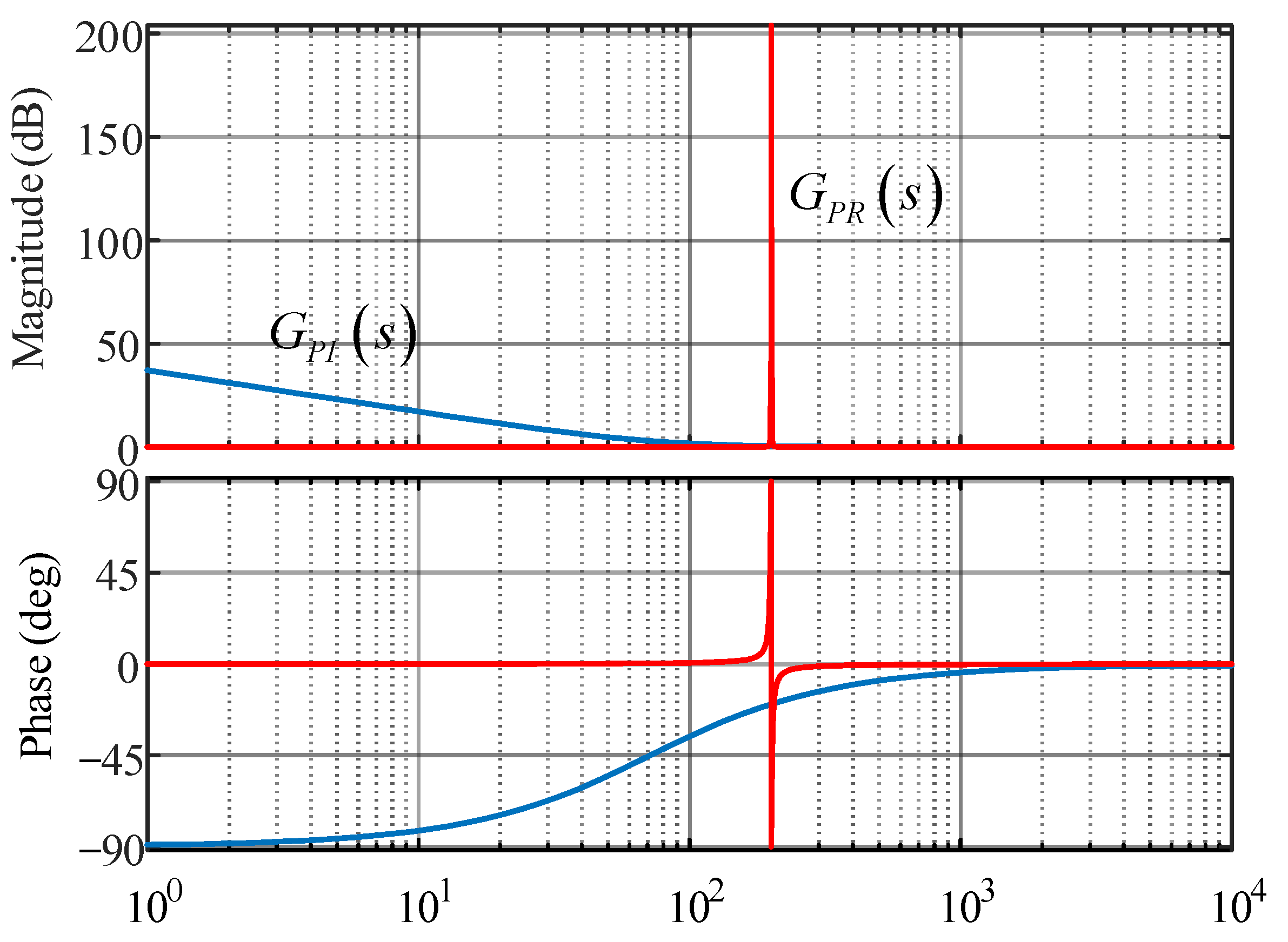
The amplitude–frequency characteristic curves of the PI controller and PR controller are further drawn, as shown in Figure 3.
According to Figure 3, the gain of the PI controller is larger than that of the PR controller at low frequencies less than the fundamental frequency of the grid-connected current, while the gain of the PR controller is larger near the low-order harmonic frequency that needs to be suppressed, and the gain of the two controllers is the same at frequencies greater than the low-order harmonic frequency. Therefore, from the comparison of amplitude–frequency characteristic curves, it is also proved that PR controllers are superior to PI controllers in control of low-frequency harmonic suppression. Here, ‘zero-steady-error’ refers to the characteristic that the steady-state deviation between the APF output compensation current and the reference harmonic current tends to zero under ideal conditions, which is derived from the infinite gain of the PR controller at the resonant frequency in the continuous-time domain (Equations (22)–(24)). However, in practical digital systems, tiny residual errors may exist due to discretization effects and hardware limitations.
Compared with the PI controller, although the PR controller has almost infinite gain at the low-order resonant frequency point and can achieve statically error-free control, its bandwidth is narrow, the phase angle margin is small, and the output current of the APF is prone to oscillation. Meanwhile, in the actual control system, due to the limitations of sampling accuracy and the digital accuracy of the controller, the resonant frequency point of the PR controller is prone to offset, so it is difficult to achieve good control in the actual system. The performance of PR controllers needs to be further improved.
By adding a high-gain low-pass filter to the proportional integral link in Equation (10),
H s = K p + K i ω c s + ω c
We can obtain
G Q P R s = k p q + 2 k i q ω c s + ω c s 2 + 2 ω c s + ω 0 2 + ω c 2
In the formula, ω c is the cut-off frequency of the low-pass filter. In the actual working conditions, ω c ω 0 , then (26) is simplified to
G Q P R s = k p q + 2 k i q ω c s s 2 + 2 ω c s + ω 0 2
Equation (27) is the S-domain transfer function form of the quasi-proportional resonant controller, and its Bode diagram is shown in Figure 4.
It can be seen from Figure 4 that, although the gain of the quasi-PR controller at the resonant frequency is not as high as that of the PR controller, it is still sufficient to meet the control goal of achieving zero steady-state error. Meanwhile, the phase angle margin is infinitely large, which can make the system have good steady-state characteristics.

3.2. Quasi-PR Control Parameter Setting

There are four parameters in the transfer function of the quasi-PR controller, ω 0 = 100 π h   rad / s is known, where h is the harmonic number to be treated ( h = 2 , 4 , 5 , 7 , 11 ), so the control parameters to be designed and adjusted are k p q , k i q , and ω c .
Adjusting the parameters ( k p q , k i q , ω c ) of the quasi-PR controller can change its frequency characteristics. Increasing the system’s proportional gain coefficient k p q value can enhance the adjustment strength of the system and shorten the adjustment time. But at the same time, it will weaken the role of the resonant link, leading to the decline of system stability and narrow bandwidth. Increasing the value of k i q can significantly improve the gain of the controller at the resonant frequency, strengthen the resonant effect, and more effectively suppress the steady-state error at that frequency. This parameter has little effect on system bandwidth. Changing the ω c value will broaden the bandwidth of the controller. At this time, the gain of the controller at the fundamental frequency remains unchanged, but the gain at other frequency points near the fundamental frequency will increase accordingly. The influence of quasi-PR controller parameters on the system is analyzed in detail below.
(1)
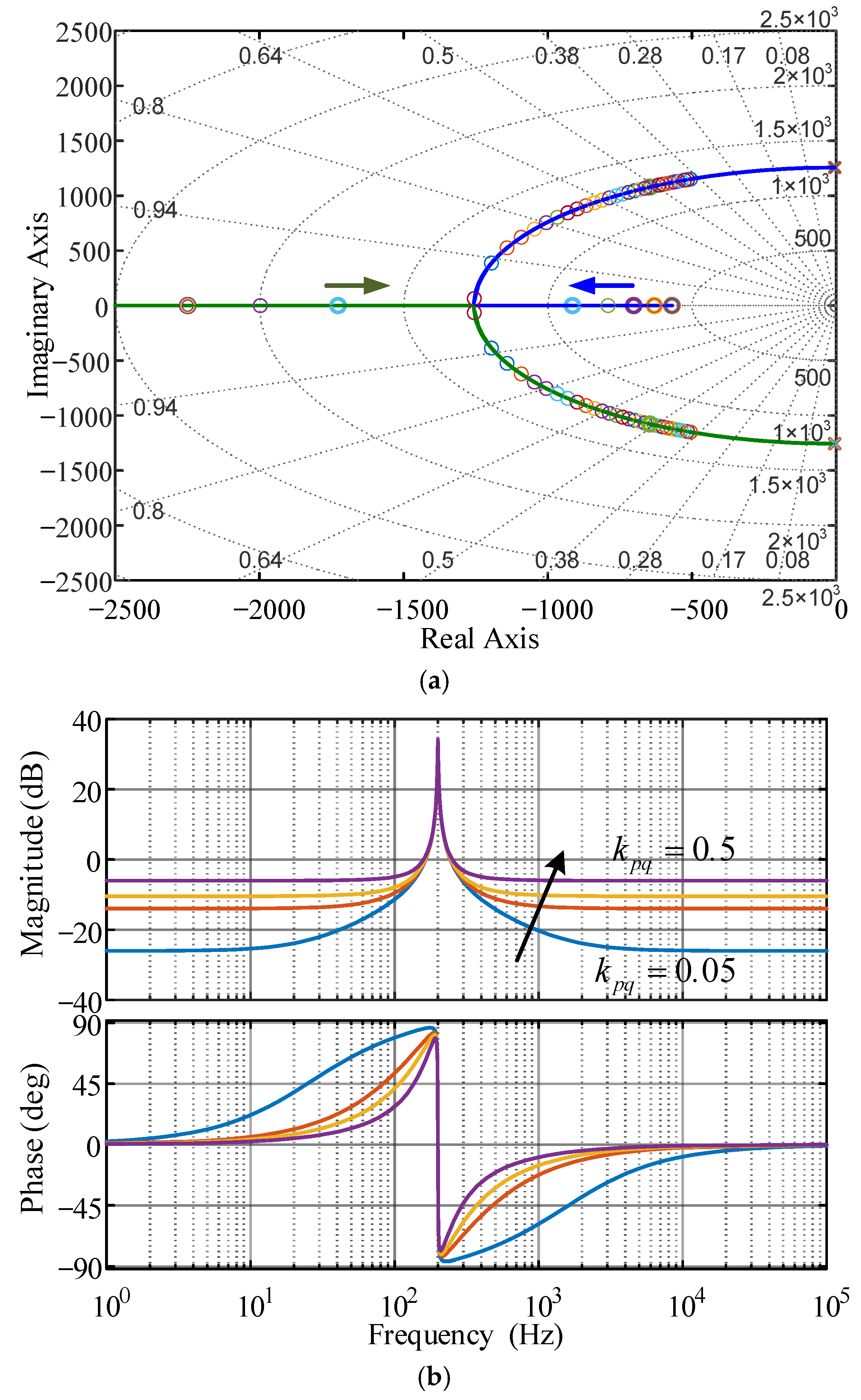
The influence of control parameter k p q .
Let k i q = 50 , ω c = 5   rad / s . When k p q changes from 0.05 to 0.50, the root locus and Bode diagram of the quasi-PR controller are obtained, as shown in Figure 5.
Figure 5 shows that the root locus and all zeros and poles of the system are located in the left half-plane, indicating that the system is stable. However, with the increase in proportional gain coefficient k p q , the root locus of the system will move to the right half-plane, resulting in a reduction in system stability (reduction in stability margin). It is worth noting that increasing the value of k p q does not change the gain of the system at the resonant frequency point, but it does increase the system’s gain margin and bandwidth. In conclusion, parameter k p q can effectively adjust the system’s bandwidth and phase margin, and then affect the dynamic response characteristics and steady-state performance of the system. From the root locus, it can be seen that when the value of k p q is small, the zeros and poles are located in the left half-plane, and the system stability is better at this time. Therefore, when selecting the k p q value in the actual design, we should avoid taking too large a value to maintain good stability.
(2)
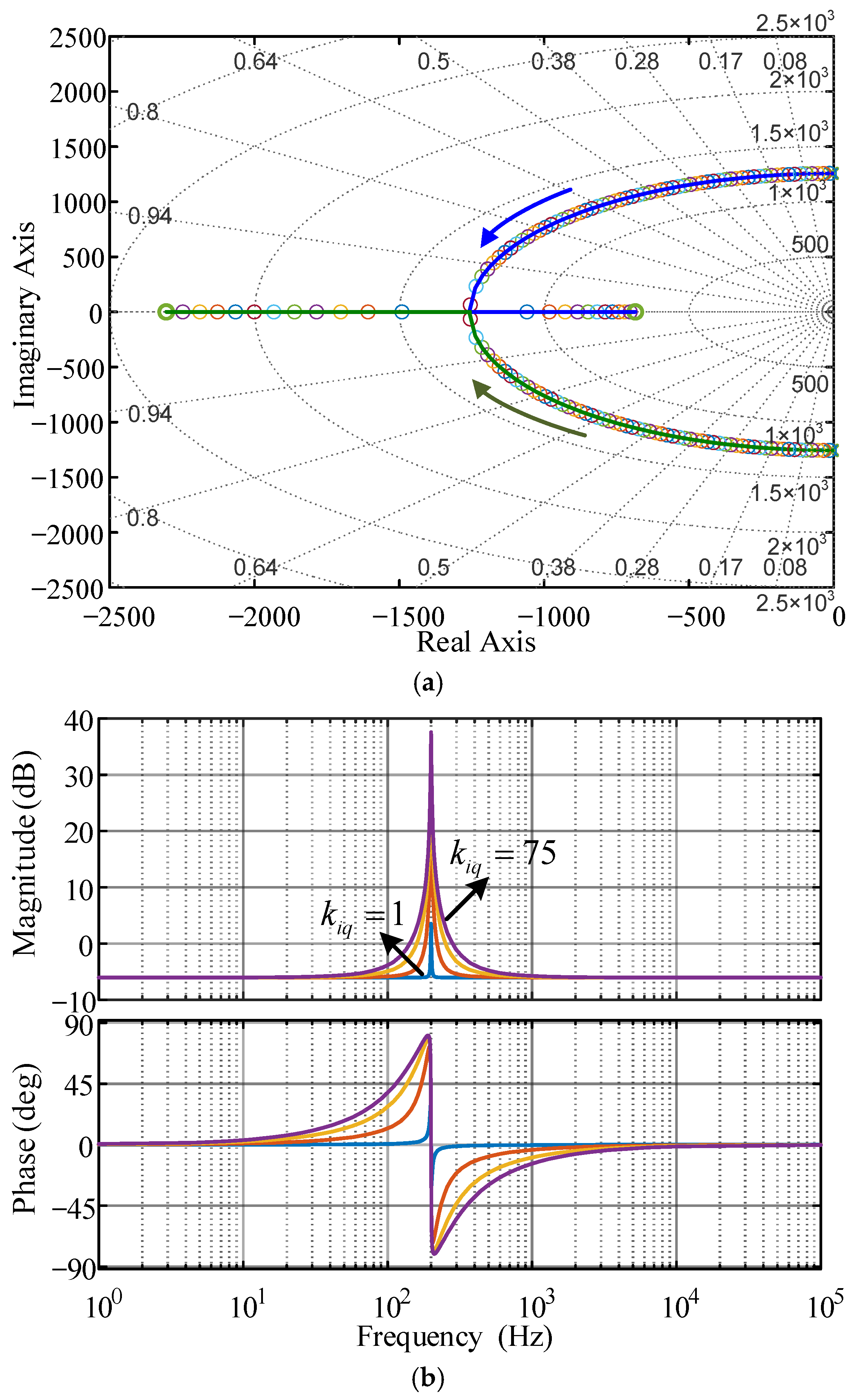
The influence of control parameter k i q .
Let k p q = 0.5 , ω c = 5   rad / s . When k i q changes from 1 to 75, the root locus and Bode diagram of the quasi-PR controller are obtained, as shown in Figure 6.
As illustrated in Figure 6, the root locus, along with all zeros and poles of the system, resides in the left half-plane—an indicator of the system’s stability. When the resonant gain coefficient k i q is elevated, the displacement amplitude of the system’s root locus remains relatively modest. Concurrently, the system’s gain at the resonant frequency point experiences a notable increase; this enhances the functionality of the resonant link and effectively diminishes the steady-state error at that specific frequency. Furthermore, increasing the value of k i q expands the control bandwidth in the vicinity of the resonant point, yet exerts minimal influence on the gain at other frequencies. Drawing on the above analysis, parameter k i q primarily impacts two aspects of the system: the steady-state error and the bandwidth near the vibration point. Consequently, in practical design processes, a slight increment in k i q can be considered to boost the resonant link’s capacity to suppress interference at a specific frequency. While root locus analysis demonstrates that the system’s zeros and poles consistently lie in the left half-plane within the range of k i q variations—signifying favorable overall stability—it is important to note that an excessively large k i q value may still compromise the system’s stability.
(3)
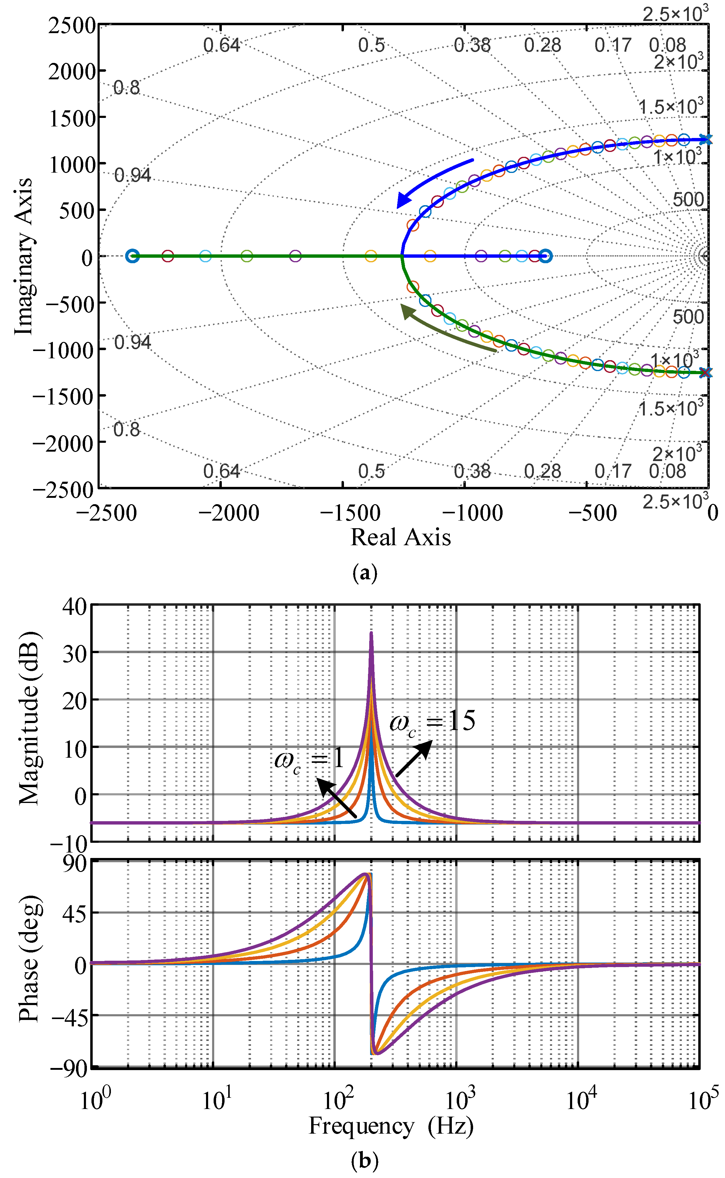
The influence of control parameter ω c .
Let k p q = 0.5 , k i q = 50 . When ω c changes from 1 to 15, the root locus and Bode diagram of the quasi-PR controller are obtained, as shown in Figure 7.
It can be seen from Figure 7 that the system root locus and all zeros and poles are located in the left half-plane, indicating that the system has stability. When the bandwidth coefficient ω c is increased, the root locus of the system gradually moves towards the real axis, and the zero position is far away from the coordinate origin. This change helps to reduce the overshoot of the system. It is worth noting that increasing the ω c value will not change the gain of the system at the resonant frequency point, but will significantly broaden the overall bandwidth of the system. Specifically, the increase of ω c mainly widens the control bandwidth in the frequency range near the resonant point, but has little effect on the gain at other frequencies. Based on the above analysis, the core function of parameter ω c is to adjust the system bandwidth, and its increase will enhance the ability of the system to suppress dynamic disturbances such as grid frequency fluctuations. Although the increase of ω c improves the dynamic response (reduces overshoot) and widens the bandwidth, it is still necessary to select its value reasonably according to the specific requirements in the actual design.

4. Experimental Results

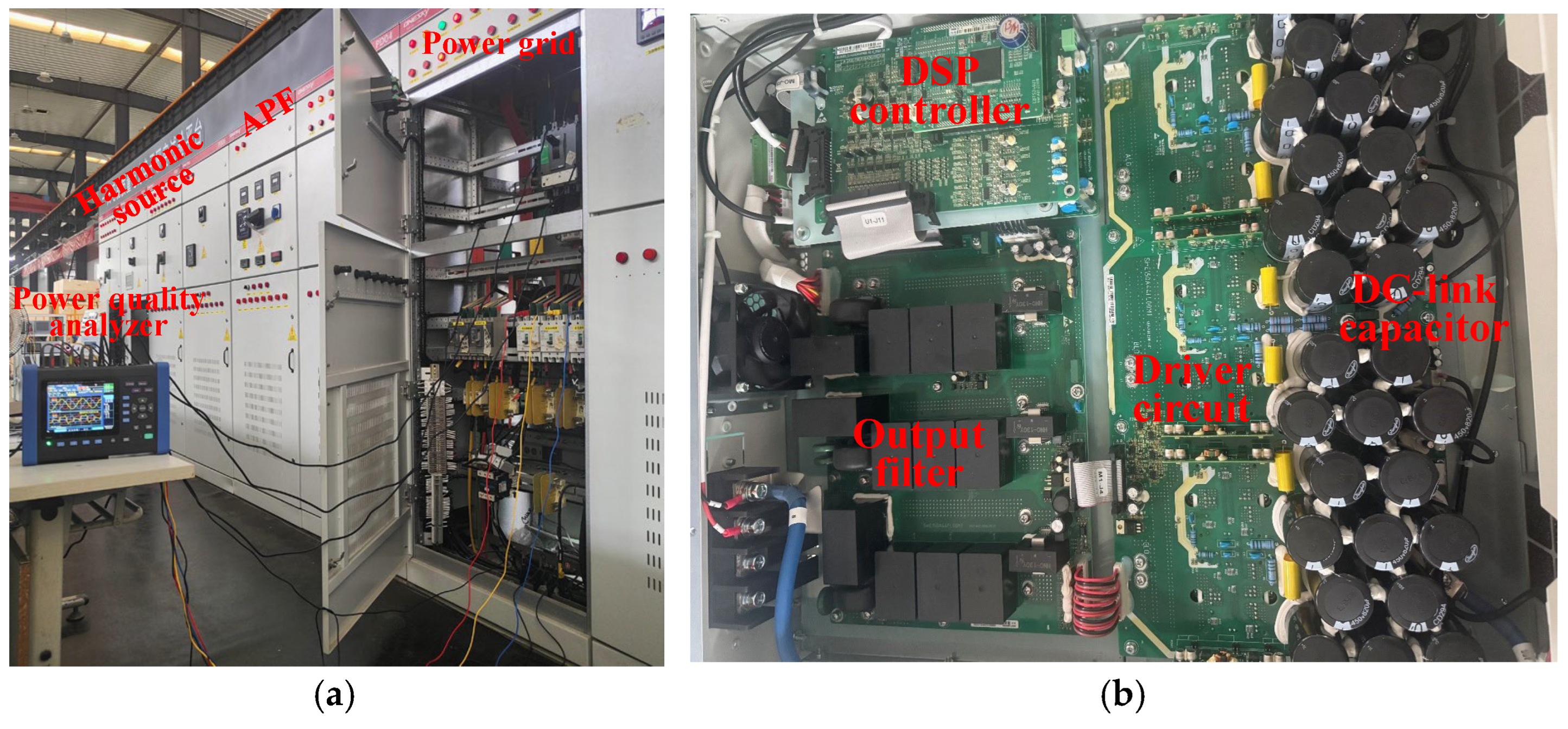
Figure 8a is a picture of the experimental platform site, including the power grid, nonlinear harmonic load, and APF industrial prototype, which can be used to verify the performance of the control algorithm proposed in this paper. Then, Figure 8b shows the internal hardware of the APF module, including the DC side energy storage capacitor, drive circuit, output filter, and TI TMS320F28335 digital signal processor (DSP). The DSP is widely used in power electronic control scenarios due to its high computational efficiency (150 MHz clock frequency) and dedicated peripheral modules for power conversion.
To simulate the actual industrial harmonic pollution scenario (where nonlinear loads often include both passive rectifiers and active power electronic devices), the experimental platform adopts an active–passive hybrid nonlinear load configuration. The passive part consists of a three-phase uncontrolled rectifier bridge with a resistance–inductance load, which is a typical source of harmonics (third, fifth, seventh, etc.) in industrial systems. The active part uses a three-phase voltage-source inverter (VSI) (composed of six insulated gate bipolar transistors (IGBT), model FF300R12KE4) controlled by a dedicated DSP (TI TMS320F28069), which is used to simulate the second and fourth low-harmonic characteristics of active power electronic devices. In the experiment, hardware and software parameters are shown in Table 1. The experimental results were measured using a HIOKI PW3198 power quality analyzer.
After the 380 V bus is connected to the nonlinear load, in addition to the characteristic harmonic currents such as the fifth and seventh harmonic currents, the bus current also contains the second harmonic current of 47.80 A and the fourth harmonic current of 25.84 A, resulting in serious distortion of the bus current, and the current THD reaches 82.18%, as shown in Figure 9a. When the APF adopts the PI control algorithm to suppress these harmonic currents, the sinusoidal degree of the current at the 380 V bus is improved, as shown in Figure 9b. The values of the second harmonic current and the fourth harmonic current also decrease to 9.27 A and 5.44 A, respectively. However, the THD of the 380 V bus current is still as high as 16.00%. This is unacceptable in some industrial environments with high requirements for power quality. Furthermore, the QPR control algorithm is implemented in the APF’s DSP. By using the control parameters designed in this paper, the contents of the second and fourth harmonic currents in the 380 V bus current are reduced to 0.72 A and 0.51 A, respectively, and the other harmonic currents are almost 0. As shown in Figure 9c, the THD is reduced to 3.45%, and the current waveform has a high sinusoidal degree. It is proved that the QPR control algorithm proposed in this paper has a good suppression effect on low-order harmonic currents such as the second and fourth.

5. Conclusions

Aiming at the problems of the large steady-state error of traditional PI control and the narrow bandwidth of PR control when an APF suppresses low-order harmonic currents, a harmonic suppression method based on quasi-proportional resonance is proposed in this paper. By establishing a synchronous, rotating coordinate system model and introducing a low-pass filter with an adjustable cut-off frequency into the PR controller, the system bandwidth is significantly broadened and the ability to resist frequency drift is enhanced. The experimental results show that the total harmonic distortion (THD) of 380 V bus is reduced from 16.00% of PI control to 3.45%, and the second and fourth harmonic currents are suppressed from 47.80 A and 25.84 A to 0.72 A and 0.51 A, respectively, with a suppression rate of over 98%. The research results provide theoretical support and solution reference for the treatment of low-order harmonic groups in the scenarios of new energy grid connection.

Author Contributions

Conceptualization, Y.L.; methodology, Y.L.; software, S.Z.; formal analysis, S.Z.; data curation, S.Z.; writing—original draft, S.Z.; resources, H.H. supervision, H.H.; writing—review and editing, Y.L. and H.H.; project administration, S.Z. All authors have read and agreed to the published version of the manuscript.

Funding

This research received no external funding.

Data Availability Statement

Data are contained within the article.

Conflicts of Interest

The authors declare no conflicts of interest. Author Yu Li is employed by the Anhui Onesky Power Quality Technology Co., Ltd. The remaining authors declare that the research was conducted in the absence of any commercial or financial relationships that could be construed as a potential conflict of interest.

References

  1. Lin, Z.; He, L.; Zhou, H. Adaptive Low-Order Harmonic Currents Suppression in AC Power System Using Fractional-Order Circuit. IEEE Trans. Circuits Syst. I Regul. Pap. 2024, 71, 4446–4457. [Google Scholar] [CrossRef]
  2. Balenciaga, J.X.; Alcaide, A.M.; Leon, J.I.; Aldazabal, E.; Madariaga, D.; Legarra, I.; Franquelo, L.G. Discontinuous PWM Technique with Reduced Low-Order Harmonic Distortion for High-Power Applications. IEEE Trans. Ind. Electron. 2023, 70, 9741–9750. [Google Scholar] [CrossRef]
  3. Wang, S.; Li, Y.; Zhang, M.; Peng, Y.; Tian, Y.; Lin, G.; Chang, F. Harmonic Resonance Suppression With Inductive Power Filtering Method: Case Study of Large- Scale Photovoltaic Plant in China. IEEE Trans. Power Electron. 2023, 38, 6444–6454. [Google Scholar] [CrossRef]
  4. Xue, G.; Chen, B.; Tian, C.; Yuan, J.; Zhou, Y.; Chen, G.; Luo, Y.; Chen, Y. A Novel Hybrid Active Power Filter with Multi-Coupled Coils. Electronics 2021, 10, 998. [Google Scholar] [CrossRef]
  5. Freitas, S.; Oliveira, L.C.; Oliveira, P.; Exposto, B.; Pinto, J.G.; Afonso, J.L. New Topology of a Hybrid, Three-Phase, Four-Wire Shunt Active Power Filter. Energies 2023, 16, 1384. [Google Scholar] [CrossRef]
  6. Xiang, Z.; Pang, Y.; Wang, L.; Wong, C.-K.; Lam, C.-S.; Wong, M.-C. Design, control and comparative analysis of an LCLC coupling hybrid active power filter. IET Power Electron. 2020, 13, 1207–1217. [Google Scholar] [CrossRef]
  7. Amerise, A.; Mengoni, M.; Rizzoli, G.; Zarri, L.; Tani, A.; Casadei, D. Comparison of Three Voltage Saturation Algorithms in Shunt Active Power Filters With Selective Harmonic Control. IEEE Trans. Ind. Appl. 2020, 56, 2762–2772. [Google Scholar] [CrossRef]
  8. Liu, J.; Dai, S.; Chen, Q.; Tao, K. Modelling and Industrial Application of Series Hybrid Active Power Filter. IET Power Electron. 2013, 6, 1707–1714. [Google Scholar]
  9. Baliyan, A.; Jamil, M.; Rizwan, M.; Alsaidan, I.; Alaraj, M. An Intelligent PI Controller-Based Hybrid Series Active Power Filter for Power Quality Improvement. Math. Probl. Eng. 2021, 2021, 1–10. [Google Scholar] [CrossRef]
  10. Li, Z.; Ren, M.; Chen, Z.; Liu, G.; Feng, D. A Bi-Sliding Mode PI Control of DC-Link Voltage of Three-Phase Three-Wire Shunt Active Power Filter. IEEE J. Emerg. Sel. Top. Power Electron. 2022, 10, 7581–7588. [Google Scholar] [CrossRef]
  11. Gao, C.; He, S.; Cui, B.; Zhang, B.; Ming, L.; Leung, K.N.; Loh, P.C. Quantization Effects on Digital-PR-Controlled Active Power Filter. IEEE J. Emerg. Sel. Top. Power Electron. 2023, 11, 5785–5797. [Google Scholar] [CrossRef]
  12. Wang, D.F.; Qian, J.L.; Bao, Y.X. The Active Power Filter Research Based on ANN Harmonic Detection and PR Control. Adv. Mater. Res. 2011, 403–408, 1668–1671. [Google Scholar] [CrossRef]
  13. Zhang, G.; Hu, W.; Cao, D.; Huang, Q.; Yi, J.; Chen, Z.; Blaabjerg, F. Deep Reinforcement Learning-Based Approach for Proportional Resonance Power System Stabilizer to Prevent Ultra-Low-Frequency Oscillations. IEEE Trans. Smart Grid 2020, 11, 5260–5272. [Google Scholar] [CrossRef]
  14. Mohammad, A.; Haneen Ghanayem, R.M. Nelms, Shunt Active Power Filter Voltage Sensorless Method Using A PR Controller for Unbalanced Grid Conditions. Energy Rep. 2023, 9 (Suppl. S1), 1056–1064. [Google Scholar]
  15. Bernet, D.; Stefanski, L.; Hiller, M. Integrating Voltage-Source Active Filters Into Grid-Connected Power Converters—Modeling, Control, and Experimental Verification. IEEE Trans. Power Electron. 2021, 36, 12218–12233. [Google Scholar] [CrossRef]
  16. An, Q.; Zhang, J.; An, Q.; Shamekov, A. Quasi-Proportional-Resonant Controller Based Adaptive Position Observer for Sensorless Control of PMSM Drives Under Low Carrier Ratio. IEEE Trans. Ind. Electron. 2020, 67, 2564–2573. [Google Scholar] [CrossRef]
  17. Liu, Z.; Huang, W.; Liu, S.; Wu, X.; Lai, C.S.; Yang, Y. An Improved Hydraulic Energy Storage Wave Power-Generation System Based on QPR Control. Energies 2023, 16, 647. [Google Scholar] [CrossRef]
  18. Tian, Y.; Xu, L.; Wu, Y.; Lu, J.; Li, J.; Mao, Z.; Mao, H.; Wang, P.; He, R. Impulse power detection for fusion power supply based on cascaded quasi-proportion resonance. Fusion Eng. Des. 2023, 189, 113431. [Google Scholar] [CrossRef]
  19. Cui, Y.; Yin, Z.; Luo, P.; Yuan, D.; Liu, J. Linear Active Disturbance Rejection Control of IPMSM Based on Quasi-Proportional Resonance and Disturbance Differential Compensation Linear Extended State Observer. IEEE Trans. Ind. Electron. 2024, 71, 11910–11924. [Google Scholar] [CrossRef]
  20. Zhe, W.; Ishak, D.; Hamidi, M.N. A Grid-Connected Inverter with Grid-Voltage-Weighted Feedforward Control Based on the Quasi-Proportional Resonance Controller for Suppressing Grid Voltage Disturbances. Energies 2024, 17, 885. [Google Scholar] [CrossRef]
  21. Zmood, D.N.; Holmes, D.G. Stationary frame current regulation of PWM inverters with zero steady-state error. IEEE Trans. Power Electron. 2003, 18, 814–822. [Google Scholar] [CrossRef]
  22. Behera, S.; Naik, N.V.R.; Panda, A.K.; Behera, S.K. Advanced off-board bidirectional electric vehicle charger with enhanced power quality and supporting grid resilience. Electr. Eng. 2023, 106, 3231–3242. [Google Scholar] [CrossRef]
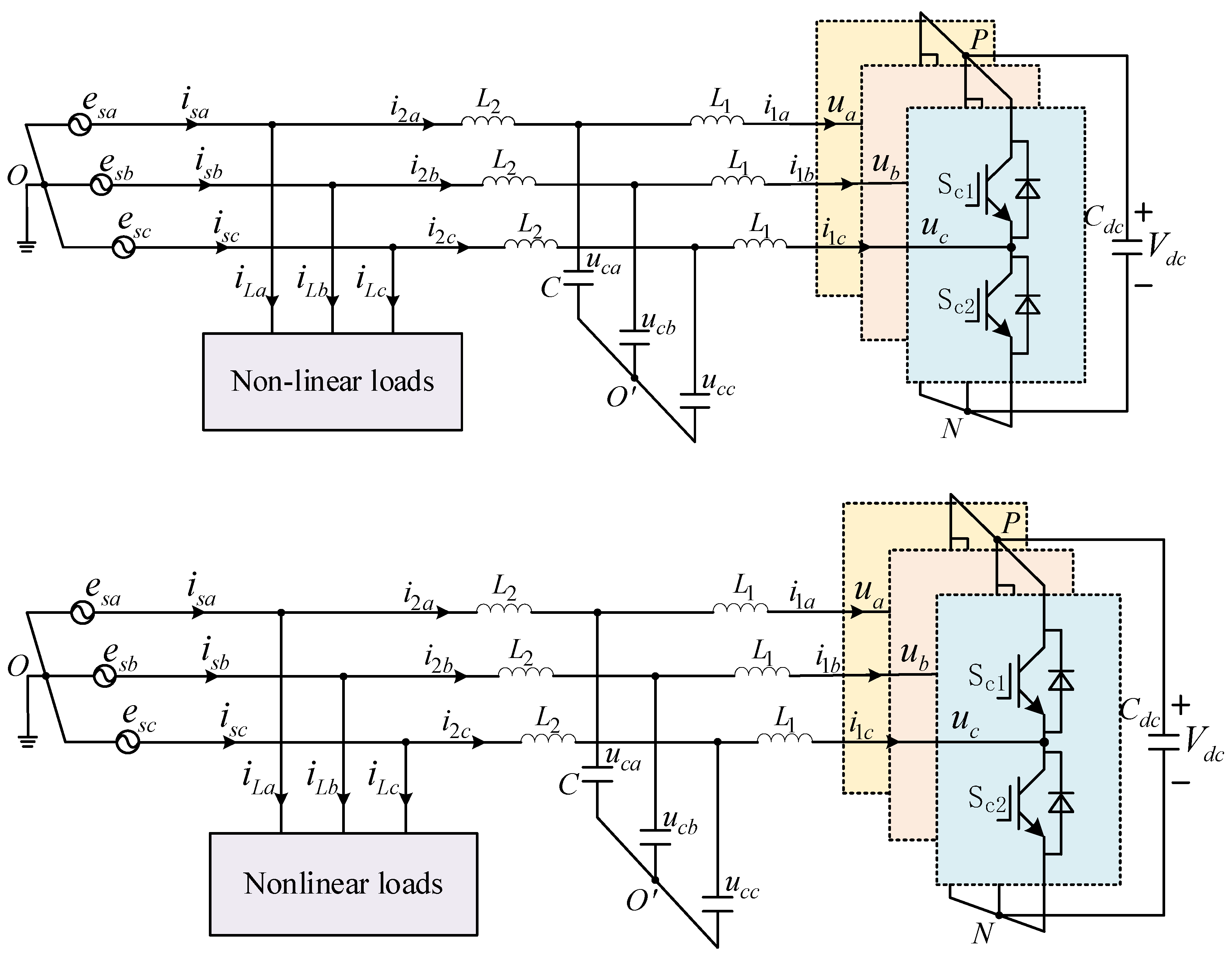
Figure 1. Topology of shunt active power filter.
Energies 18 05697 g001
Figure 2. Current loop control structure block diagram of the APF.
Energies 18 05697 g002
Figure 3. The Bode diagram of the PI controller and the PR controller.
Energies 18 05697 g003
Figure 4. Bode diagram of quasi-proportional resonant controller.
Energies 18 05697 g004
Figure 5. The influence of k p q change on the system. (a) Root locus of k p q change. (b) Bode diagram of k p q change.
Energies 18 05697 g005
Figure 6. The influence of k i q change on the system. (a) Root locus of k i q change. (b) Bode diagram of k i q change.
Energies 18 05697 g006
Figure 7. The influence of ω c change on the system. (a) Root locus of ω c change. (b) Bode diagram of ω c change.
Energies 18 05697 g007
Figure 8. Schematic diagram of the experimental platform. (a) Picture of the experimental platform site. (b) Internal hardware circuit of the APF.
Energies 18 05697 g008
Figure 9. The experimental results obtained by using the HIOKI PW3198 power quality analyzer. (a) 380 V bus current waveform and FFT when APF is not running. (b) 380 V bus current waveform and FFT when APF adopts PI control method. (c) 380 V bus current waveform and FFT when APF adopts QPR control method.
Energies 18 05697 g009
Table 1. System parameters.
SymbolQuantityValues
C d c DC-side capacitor2 mF
V d c DC-side voltage750 V
L 1 Inverter-side inductance 0.5 mH
C Filter capacitance 6 µF
L 2 Grid-side inductance 0.05   mH
R d Virtual resistor1.5 Ω
e s Grid voltage380 V
f 1 Fundamental frequency50 Hz
f s w Switching frequency20 kHz
K p i Proportional coefficient of PI controller80
K i i Integral coefficient of PI controller10
K p q Proportional coefficient of QPR controller100
K i q Resonance coefficient of QPR controller12
ω c Cut-off frequency10 rad/s
Disclaimer/Publisher’s Note: The statements, opinions and data contained in all publications are solely those of the individual author(s) and contributor(s) and not of MDPI and/or the editor(s). MDPI and/or the editor(s) disclaim responsibility for any injury to people or property resulting from any ideas, methods, instructions or products referred to in the content.