Abstract
Lift–cruise-type unmanned aerial vehicles (UAVs) powered by hydrogen fuel cells often integrate secondary energy storage devices to improve responsiveness to load fluctuations during different flight phases, which necessitates an efficient energy management strategy that optimizes power allocation among multiple power sources. This paper presents an innovative fuel cell DC–DC converter (FDC) design for the hybrid power system of a lift–cruise-type UAV comprising a multi-stack fuel cell system and a battery. The novelty of this work lies in the development of an FDC suitable for a multi-stack fuel cell system through a dual-input single-output converter structure and a control algorithm. To integrate inputs supplied from two hydrogen fuel cell stacks into a single output, a controller with a single voltage controller–dual current controller structure was applied, and its performance was verified through simulations and experiments. Load balancing was maintained even under input asymmetry, and fault-tolerant performance was evaluated by analyzing the FDC output waveform under a simulated single-stack input failure. Furthermore, under the assumed flight scenarios, the results demonstrate that stable and efficient power supply is achieved through power-supply mode switching and application of a power distribution algorithm.
1. Introduction
Rapid advances in the global aviation industry have increased both public expectations and industrial demand for unmanned aerial vehicles (UAVs). In response, research institutions and aerospace companies around the world have been accelerating the development of next-generation UAV platforms. Various UAV configurations are being actively explored, particularly those that offer high flight performance and operational flexibility. One of the most innovative configurations gaining considerable attention has been the hybrid vertical takeoff and landing (VTOL) UAV, which combines the high-speed cruising capability of fixed-wing configurations with the VTOL capability of rotary-wing configurations. Despite the inherent complexity of the control system, hybrid VTOL UAVs are a promising solution for various mission scenarios. The European Union Aviation Safety Agency defines hybrid VTOL aircraft as utilizing distributed propulsion and operating with two or more lift/cruise units [1,2].
Hydrogen fuel cells are considered a highly promising power source for UAVs because of their high energy density and environmental friendliness. However, they are generally characterized by a slow dynamic response and can only generate stable power when the hydrogen supply is constant [3,4]. This limits their responsiveness to sudden load fluctuations [5], which is particularly pronounced in systems with dynamic load profiles such as VTOL UAVs and off-road tractors, and can degrade the overall propulsion performance and shorten the lifetimes of components. To address these limitations, hybrid power systems that combine fuel cells with secondary energy storage devices such as batteries or ultracapacitors have been widely adopted [6,7]. Common topologies include single-stage, dual-stage series, and dual-stage parallel architectures [8,9], which differ in terms of system efficiency, component count, output voltage control performance, battery specification requirements, peak power handling capability, ease of control, and responsiveness to variable loads [10,11]. These considerations have driven research into energy management strategies that optimize power allocation based on the specific roles and characteristics of each power source [12,13,14]. In a hybrid power system, each power source typically operates at a different voltage level, and the output voltage can vary significantly depending on the load condition. As a result, the integration of a DC–DC converter capable of both voltage regulation and power control is essential for achieving stable and efficient operation. In addition, single-stack fuel cell systems have limited output capacity and reliability, which has led to the rise of multi-stack fuel cell systems owing to their potential scalability and fault tolerance. However, such systems frequently encounter issues such as voltage imbalance between stacks, which complicates power distribution and load sharing [15]. In powertrain systems for vehicles and ships where weight and space constraints are relatively relaxed, multi-stack fuel cell systems typically employ individual DC-DC converters for each stack. Due to the relatively loose constraints on the weight and size of components, a higher-level controller responsible for energy management and power distribution is additionally configured, enabling relatively easy operation of each individual converter [16,17,18]. However, in applications with stringent size and weight limitations, such as UAVs, there is a need for a lightweight and compact hydrogen fuel cell power conversion system capable of controlling multiple buck converters simultaneously through a single unified controller while performing power distribution.
This paper presents the design and control strategy of a dedicated fuel cell DC–DC converter (FDC) tailored for a lift–cruise-type UAV powered by a fuel cell/battery hybrid power system. The key innovations and research contributions are summarized as follows:
- Development of an FDC capable of accommodating two independent input power sources from a multi-stack fuel cell system.
- Implementation of a dual-input single-output converter structure that simultaneously delivers power to both the inverter and battery charging circuit.
- Integration of efficient load balancing and power distribution algorithms into a unified control strategy.
- Ensuring optimal utilization of each power source under rapidly changing load conditions to enhance the UAV’s propulsion system responsiveness and stability.
In Section 2, the specifications of the system where the proposed fuel cell DC–DC converter (FDC) is applied are described in detail, highlighting the differences from conventional powertrain systems. Section 3 explains the topology and design of the proposed FDC, along with the control algorithms and energy management functions. Section 4 presents verification of the controller and energy management functionality through simulations. Section 5 deals with ground-based experimental tests simulating the unmanned aerial vehicle on an ironbird test bed. Finally, Section 6 concludes the paper.
2. Lift-Cruise Type UAV Power System Specifications
Figure 1a shows the lift–cruise-type UAV considered in this study. The UAV has a propulsion system comprising six 3.5 kW lift motors for hovering and a 10 kW pusher motor for cruising. Figure 1b shows the power system, which comprises four 2.5-kW fuel cell stacks, two lithium-ion battery packs, and FDCs for power conversion and distribution. During the takeoff phase, which requires the instantaneous peak power, power is delivered directly from the pre-charged battery packs to the lift motors. During the cruise phase, the fuel cells function as the primary power source and supply power to the pusher motor. Any excess power generated during this phase is utilized to charge the battery packs and thus enhance the energy utilization efficiency. The outputs of the two FDCs, which are each rated at 5 kW, are combined by the side power distribution unit (SPDU) and main power distribution unit (MPDU), and the aggregated power is delivered to the pusher motor during the cruise phase. The MPDU functions as the upper-level controller: it manages and supervises all data related to power sources including the operating states of the FDCs and fuel cell stacks. The SPDU distributes the output from the FDCs to either the battery packs or pusher motor depending on the operational mode of the hybrid power system. A stack control unit continuously monitors key operational parameters such as the stack output voltage, current, temperature, and hydrogen flow rate to ensure the safe and efficient operation of each fuel cell stack. Each battery pack comprises 26 cells configured in series to provide a nominal voltage of approximately 100 V.
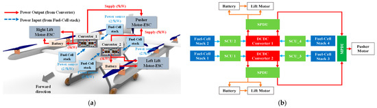
Figure 1.
Hybrid power system for Lift-Cruise UAV: (a) Configuration; (b) Block diagram.
In the design of the power system for an UAV with a target takeoff weight of approximately 150 kg, a maximum power output of 31.6 kW is required, which includes lift motors (3.6 kW × 6 units, totaling 21.6 kW) and a pusher motor with a maximum output of 10 kW. To operate at this maximum power for 30 min, a battery/hydrogen fuel cell hybrid power system is configured, comprising a 350-bar compressed hydrogen tank and a 10 kW fuel cell stack capable of operating for one hour. Assuming a hydrogen energy density of 33.3 kWh/kg based on Lower Heating Value (LHV), a fuel cell stack density of 55%, and utilization of up to 80% of the hydrogen tank capacity, the required hydrogen mass for the UAV operation is calculated to be 683 g (10,000 [W]/33.3 [kWh/kg]/55 [%]/80 [%]). Based on this, the hydrogen fuel cell system consists of four fuel cell stacks (including air and hydrogen supply systems, totaling 15.4 kg), a thermal management unit (2.3 kg), an air filter (0.1 kg), a water discharge pipe (0.1 kg), a hydrogen tank (7.7 kg), supply and transfer units (0.7 kg), and a pressure measurement device (0.3 kg), with a total weight of 27.6 kg. Under the same weight conditions, a pure battery system can be designed using TATTO’s 26S 16,000 mAh battery cells arranged in a 26S15P configuration, assuming that packaging weight accounts for approximately 10% of the battery weight. Both systems offer comparable sustainable operating time and similar weight characteristics; however, the pure battery system directly supplies all power from the battery, causing the battery load to continuously increase as the state of charge decreases. In contrast, the hybrid system supplies stable power through the fuel cell, reduces the battery load, and uses surplus power during low-speed cruise phases to recharge and protect the battery, enabling efficient energy management for long-distance flights.
Furthermore, transitioning the pure battery system to a multi-stack fuel cell system could increase the number of converters, thereby adding system weight. However, by applying the multi-input single-output (MISO) FDC proposed in this paper, the number of connectors can be reduced and power distribution and energy management algorithms can be integrated, enabling hybrid power system configuration without additional controller or equipment weight. Each converter weighs approximately 1.25 kg and provides 5 kW output. To support a 10 kW fuel cell system, two converters are used. For battery charging power, each converter handles 3 kW, and for driving the 10 kW-class pusher motor, each converter supplies 5 kW.
Figure 2 illustrates the block diagram of a hydrogen fuel cell-based battery hybrid power system. Figure 2a depicts the conventional configuration commonly used in vehicles or ships without stringent weight or size constraints, where each fuel cell stack is paired with an individual converter. Figure 2b shows the proposed block diagram applying the dual-input single-output (DISO) Fuel Cell DC-DC Converter (FDC) structure. The FDC controller not only manages converter operation but also integrates energy management algorithms, power distribution, and load balancing functions. This integration simplifies the architecture of the hybrid power system and reduces the number of components.
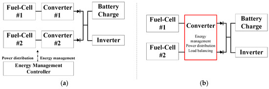
Figure 2.
Block diagram of hybrid power system: (a) Block diagram of a power system with an individual converter for each fuel cell stack; (b) Block diagram of the proposed integrated dual-input single-output (DISO) FDC-based power system.
3. Proposed Fuel-Cell DC-DC Converter (FDC)
3.1. Proposed Topology of FDC
Figure 3 shows the topology of the proposed FDC. For communication purposes, a controller area network interface was implemented to receive power mode commands from the MPDU. In the UAV, each fuel cell stack has an operating voltage range of 110–180 V while a voltage of approximately 100 V is required to drive the motors and charge the battery packs. Therefore, the FDC was designed to operate in buck mode to step down the voltage to appropriate levels. Given the space and weight constraints inherent to UAVs, minimizing the number of control units is essential. The FDC utilizes a single microcontroller unit (MCU) to control four individual buck converter circuits. The switching frequency was set to 40 kHz based on the computational time requirements for the interrupt-driven execution of two voltage controllers and four current controllers. The rated output current was set to 25 A. To optimize the inductor design, the inductor current ripple ratio should be 0.3. Based on this criterion, the initial inductance was calculated using Equation (1) to be 95.2 µH:
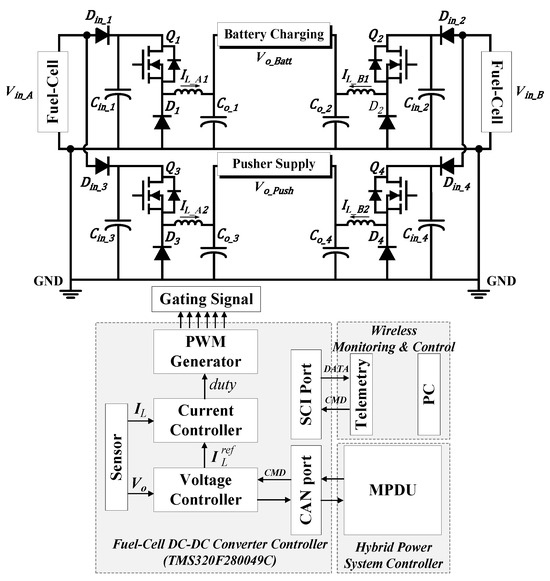
Figure 3.
Topology of the proposed FDC and its control.
The input voltage was set to 130 V, which corresponds to the steady-state output voltage of a fuel cell stack, while the output voltage was set to 100 V, which corresponds to the required voltage to drive the UAV and charge the battery packs. To account for thermal considerations and ensure a safety margin under ambient conditions, the final inductance was set to 106 µH.
Figure 4 presents a 3D model of the FDC. Two input channels are located on either side of the FDC, and two output connectors are positioned on the top surface for optimal accessibility. The four inductors of the buck converter circuits are mounted on the top side to facilitate efficient thermal dissipation via cooling fans. Switching components and diodes are placed on the bottom side, where they can be cooled by an integrated heatsink.
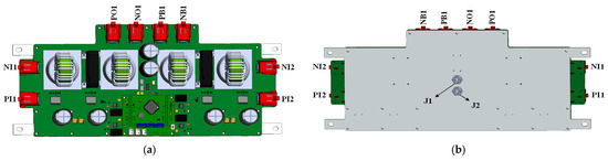
Figure 4.
Three-dimensional model of the FDC: (a) top view; (b) bottom view.
3.2. Control Method
The multi-stack fuel cell system consists of multiple stacks generating one output, requiring that each stack shares the load equally. To meet this requirement, the control algorithm adopts a single voltage controller–dual current controller structure. In this structure, two current controllers equally share the output of a single voltage controller to balance the load across the stacks. The single voltage controller acts as a master, while the dual current controllers act as slaves. When the number of input stacks increases to n, the number of current controllers also increases proportionally to n, enabling balanced load sharing and facilitating flexible scalability of the system capacity. Beyond scalability, the use of a multi-stack fuel cell system also allows for redundancy of the power source, enhancing system reliability. Additionally, the proposed FDC’s dual-input single-output hardware and software architecture contributes to improved safety by supporting fault tolerance. This structural and functional design ensures that the system can continue to operate reliably even if one stack encounters issues, effectively securing stability and continuity in power supply.
Figure 5a–c all represent control block diagrams. Figure 5a is the voltage controller, Figure 5b is the current controller, and Figure 5c is the single voltage controller with dual current controller block diagram. The dual-loop control structure in Figure 5c can be interpreted as having a master–slave architecture, as illustrated in Figure 5d, which offers the advantage of flexible scalability for future expansion of the system capacity. The transfer functions for the current control (inner loop) and voltage control (outer loop) of the FDC are derived in both the continuous-time and discrete-time domains to facilitate the design of a cascaded control system.
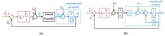
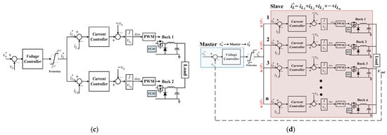
Figure 5.
Control block diagram: (a) voltage control; (b) current control; (c) Single voltage controller with dual current controller; (d) master–slave (i.e., multi-input single-output) structure for capacity expansion.
For the current control loop in the continuous-time domain, the plant is modeled as an average inductor with series resistance, which leads to the following transfer function:
When proportional–integral (PI) controller is applied, the open-loop transfer function becomes:
Assuming ideal pole-zero cancelation, the resulting closed-loop transfer function simplifies to a first-order system:
where and are the P and I gains, respectively, and is the desired bandwidth of the current control loop.
For the voltage control loop, the plant is modeled as a capacitor integrating the current:
When combined with PI controller, the open-loop transfer function is
where and are the P and I gains, respectively, of the voltage control loop. The closed-loop transfer function takes the form of a standard second-order system:
In the discrete-time domain, the plant of the current control loop can be discretized as:
where , , and is the sampling time.
PI controller is expressed as:
For the voltage control loop, the capacitor-based plant is discretized as:
When combining with the discrete PI controller, the closed-loop transfer function is given by
Figure 6 illustrates the bode plots of the current and voltage control loops. In this study, the bandwidth of the designed current controller is approximately 13 kHz, which is about one-third of the sampling frequency (40 kHz). The phase margin is 53.6 degrees, and the gain margin is 17.8 dB, indicating that while the controller may be sensitive to noise, it offers the advantage of fast response. The bandwidth of the voltage controller is approximately 2 kHz, slower than that of the current controller, but the controller gain values were selected to ensure stable response. As shown in Figure 6, the gain tuning of these controllers was performed to leverage the fast response advantage of the inner current control loop in the multi-input single-output structure, while ensuring control stability through the outer voltage control loop.
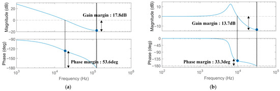
Figure 6.
Bode plots of FDC control loops: (a) current; (b) voltage.
The control signal is generated by the voltage control loop based on the error between the reference and feedback voltage, as given in (13):
The reference current is evenly distributed to the two input channels:
Each current control loop error is computed as:
Then, the pulse-width modulation duty command for each channel is calculated through the corresponding PI current control:
3.3. Under-Voltage Lock Out
In proton exchange membrane fuel cells, reversible performance degradation occurs because of the oxidation of platinum catalysts, which reduces the electrochemically active surface area and in turn decreases the output voltage. A common approach to address this issue is periodic short-circuiting, which enables performance recovery by the regular removal of surface oxides [19,20,21]. This process occurs in cycles with each fuel stack short-circuiting for approximately 50–200 ms. Thus, a single FDC unit can experience moments when the input voltage of the A side or B side channels momentarily drops close to 0 V, as shown in Figure 7. Given the structure of the FDC, which has four buck converter circuits paired into two sets, this transient condition poses the risk of reverse current flow from the output to the input side. To prevent this, an under-voltage lock out (UVLO) function was integrated into the control strategy [22,23]. The UVLO function detects the input voltage of the two channels; when a point lower than the required voltage of 100 V is detected, all switching operations of the corresponding channel are turned off so that only one channel performs power conversion.
Figure 7.
Periodic short-circuiting of a fuel cell: (a) schematic; (b) output characteristics.
3.4. Power Distribution
During the operation of the hybrid power system, a key function of the FDC is to allocate the output power from the fuel cell stacks according to the defined operational priority. In the propulsion system, the lift motors can be powered by auxiliary sources such as the battery packs (Figure 1). Therefore, the power supplied from the fuel cell stacks is primarily allocated to the pusher motor. When the battery packs are charging and the pusher motor is operating simultaneously, the FDC prioritizes supplying the pusher motor and then directing any remaining power to charging the battery pack. This approach ensures efficient power distribution and reliable propulsion under dynamic load conditions. Figure 8 illustrates the flowchart of the power distribution algorithm along with the corresponding output power allocation curve under actual operating conditions.
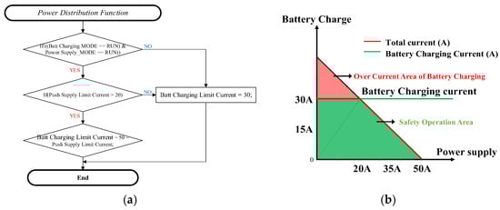
Figure 8.
Power distribution algorithm: (a) flowchart; (b) power allocation curve.
4. Simulation
4.1. Simulation Design
The load balancing algorithm for voltage and current control were validated through simulations using a model that matched all specifications of the actual FDC. As given in Table 1, parameters such as the rated power, input voltage, desired output voltage, sampling time, and switching frequency were selected to match the conditions of the actual hardware. Two different control schemes were compared: a single-loop scheme using only voltage control and the proposed dual-loop scheme incorporating both voltage and current control. The simulation setup was constructed as shown in Figure 9, utilizing battery and fuel cell models to test the proposed FDC under various flight scenarios and to evaluate the control performance under realistic operating conditions.

Table 1.
Simulation model specifications.
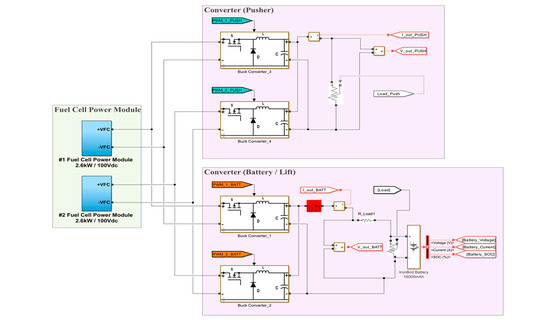
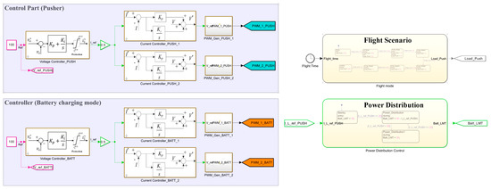
Figure 9.
Simulation model of FDC.
4.2. Simulation Results
In a multi-stack fuel cell system, multiple hydrogen stacks are connected as inputs to the converters. Since the voltages of these stacks are not always identical, simulations were conducted to verify whether the proposed converter maintains stable power conversion and achieves proper load balancing under such conditions. As shown in Figure 10, channels A and B were initially set to an equal input voltage of 120 V. Under these conditions, both control schemes exhibited a consistent current distribution across the two channels based on the inductor current waveforms. However, at t = 0.15 s, the input voltage of channel A was increased to 140 V to deliberately introduce a voltage imbalance. After this change, the single-loop scheme caused the current to flow predominantly through channel A, which resulted in an unequal current distribution. In contrast, the proposed dual-loop scheme maintained a uniform current contribution from both channels, which effectively ensured that each channel delivered approximately half of the total load current despite the voltage discrepancy.
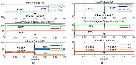
Figure 10.
Imbalanced input voltages in channels A and B: (a) single-loop control scheme (voltage-only); (b) dual-loop control scheme (voltage and current).
In the simulation of Figure 11, a scenario was modeled where one of the two stacks supplying the converter input failed. This test corresponds to a short-circuit condition, which is one of the critical characteristics of the hydrogen stacks used in the lift-cruise UAV hybrid power system addressed in this paper, and was conducted to verify the stable response of the proposed system under such faults. As shown in Figure 11, a fault was simulated in which one fuel cell stack failed completely, which eliminated the input voltage from one channel. In this case, the single-loop scheme took approximately 5 ms to shift the full load current to the remaining channel. However, the proposed dual-loop scheme responded much faster and reallocated the current within 0.9 ms to maintain a continuous power supply using the functional channel.
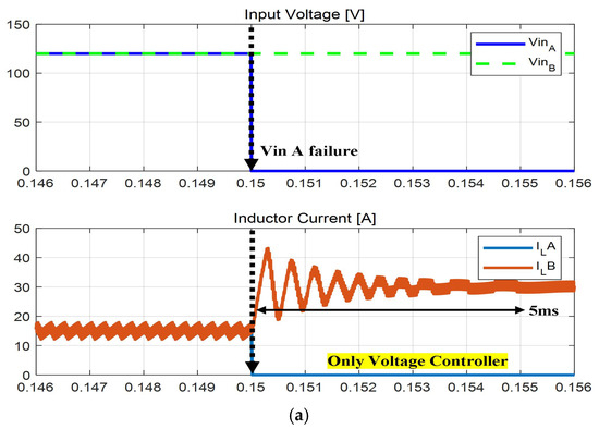
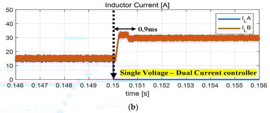
Figure 11.
Input voltage failure in channel A: (a) single-loop control scheme (voltage-only); (b) dual-loop control scheme (voltage and current).
Figure 12 compares the inductor current waveforms when using a single voltage controller and a dual voltage controller. Although the dual voltage controller maintains load balancing even with input differences between two phases, it exhibits low-frequency ripple in the inductor current waveform. Therefore, it was confirmed that using a Single Voltage Controller is more advantageous for the FDC in multi-stack fuel cell systems.
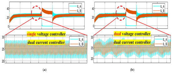
Figure 12.
Output characteristics of the inductor current: (a) single voltage controller with dual current controller (b) dual voltage controller with dual current-controller.
Figure 13 compares the output waveforms of the FDC when using the sliding mode control method and the proposed single voltage controller–dual current controller method. Under the same control parameters and plant conditions, the response time to reach the target output is approximately 1.2 ms for the proposed controller, whereas the sliding mode control method is faster by about 0.5 ms, achieving a response time of 0.7 ms. Although the sliding mode control method has a slightly faster response speed, its initial inductor current overshoot exceeds 110 A, making it unsuitable for the hybrid power system configuration proposed in this paper. Such an overshoot could potentially damage the battery or inverter. Furthermore, the ripple current in the sliding mode control method is approximately 4 A larger than that of the proposed control technique, which results in lower quality current supply to the battery charging and inverter power supply. These observations suggest that the proposed control method is more appropriate for hybrid power systems.
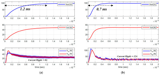
Figure 13.
Compare output characteristics of two control methods: (a) sliding mode control; (b) single voltage controller—dual current controller.
Figure 14 presents the output characteristics of the FDC according to the UAV flight phases. Stage 1 corresponds to the lift phase during which the pusher motor was inactive and all power from the fuel cells (approximately 3 kW) was utilized to charge the battery packs. Stages 2 and 3 represent the transition to the cruise phase, where the UAV began to accelerate. As the pusher motor started operating, approximately 10–20 A of the current was consumed to drive the pusher motor while the battery pack continued to be charged at the maximum allowable current of 30 A. In stage 4, the pusher motor was operating at maximum. All power generated by the fuel cells was consumed by the pusher motor, and no remaining power was available to charge the battery pack. In stage 5, approximately 40 A was allocated to the pusher motor, and the remaining 10 A was used to charge the battery. In stage 6, both the pusher motor and the battery charging current are allocated equally at 25 A. In stage 7, which corresponds to the landing phase, the pusher motor stopped operating while the lift motors started operating. Consequently, all available power from the fuel cells was directed to charging the battery packs. These results confirm that the FDC eff allocates power based on predefined operational priorities, even under constrained system conditions. Specifically, under a rated power capacity of 5 kW per FDC module and a battery charging limit of 3 kW, the controller demonstrated proper coordination between the fuel cell stacks and the battery, ensuring stable and balanced power distribution.
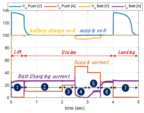
Figure 14.
Output characteristics of the proposed FDC in different flight phases: lift, cruise, and landing.
5. Experiment
5.1. Experiment Setup
As shown in Figure 15, an iron bird testbed was utilized for ground-based experiments of the hybrid power system. The testbed was built at full scale to match the dimensions of the actual UAV, and both the propulsion system and hybrid power system were configured identically to those in the UAV. The fuel cell stacks and FDCs were positioned at the center of the airframe to facilitate power distribution to the lift and pusher motors as well as charging of the battery packs.
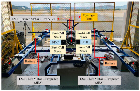
Figure 15.
Experimental setup for iron bird testbed.
The target UAV in this study, with a maximum takeoff weight of 150 kg, is equipped with six lift inverter–motor units, one pusher inverter–motor unit, and a propulsion system comprising four-blade propellers with a diameter of 35.5 inches. These components were identically installed on the iron bird platform. The power required for propeller operation and battery charging is supplied by fuel cell stacks, and the converter is designed to transform this power for delivery to each load. In addition, load cell sensors were mounted beneath each propulsion propeller module to measure the generated thrust without actual flight. This configuration enables the Iron bird test bed to achieve propeller rotational speeds that match the requirements of realistic flight profiles.
5.2. Experiment Results
Figure 16 illustrates the experimental waveforms obtained from test 1, which encompassed the full system comprising the fuel cells stacks, FDCs, motors, and inverters. The waveforms for the FDC input voltage from the fuel cell stacks, the FDC output voltage for both the pusher motor and battery charging, the output current to the pusher motor, and the battery charging current are presented. The input voltage waveform confirms that the FDC effectively regulated the input voltage from the fuel cell to maintain a stable output of approximately 100 V even as the input voltage fluctuated. The current waveforms also confirm that current was balanced well across both channels. Two hydrogen fuel cell stacks alternately experience short circuit operation causing inputs to momentarily drop close to zero; however, the single voltage controller–dual current controller maintains the targeted output of 100 Vdc through the current controller of the opposite phase. This verifies that the FDC operates suitably for multi-stack hydrogen fuel cell systems. The current waveforms in Figure 16 for the pusher motor and battery charging indicate that the FDC prioritized delivering power to the pusher motor with any surplus power being allocated to battery charging depending on the flight phase. This functionality demonstrates the energy management capability of the FDC by implementing a battery charging mode based on the power distribution algorithm, aimed at extending the actual flight time of UAVs. Figure 17 presents the experimental waveforms of the FDC subjected to sudden load changes. Regardless of the abrupt load changes, the output voltage was stably maintained at approximately 100 V throughout the test. Notably, the initial overshoot above 100 V in the output voltage to the pusher motor can be attributed to the initial no-load condition of the pusher motor (i.e., load current of 0 A). Figure 18 illustrates the efficiency of the FDC across various operating conditions. Three output modes were compared: pusher-only output, battery-only output, and simultaneous dual output. The efficiency was evaluated over a power range of 0.5–5 kW. Although the efficiency slightly decreases at output levels below the rated operating point, the system maintains a certain level of efficiency under actual operating conditions. It was also confirmed that simultaneous operation of two output channels is possible without significant efficiency degradation.
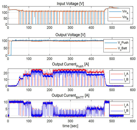
Figure 16.
Output waveforms measured during test 1.
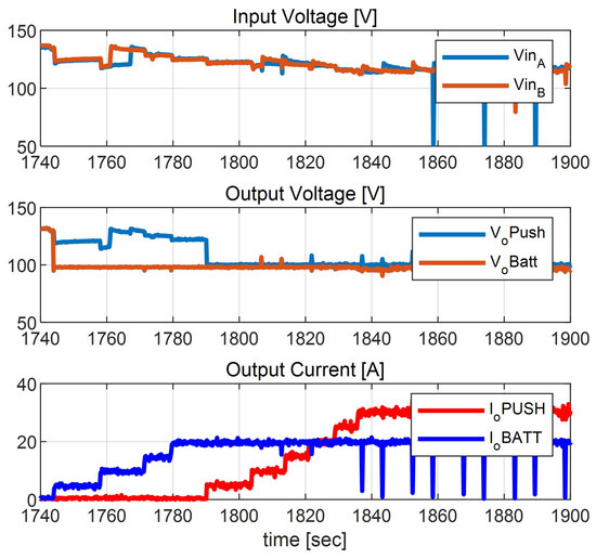
Figure 17.
Output waveforms measured during test 2.
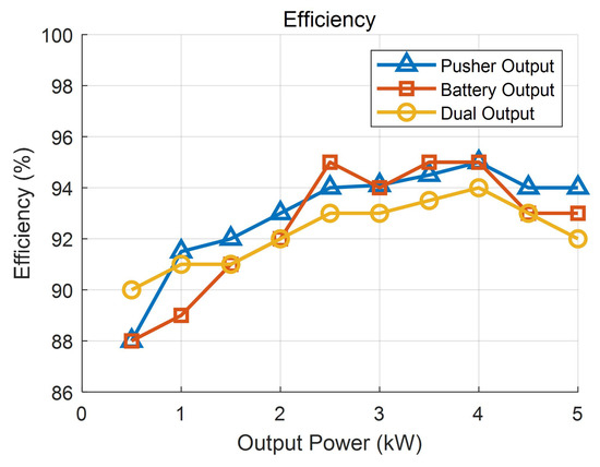
Figure 18.
Efficiency of the proposed FDC.
6. Conclusions
This study presented the design and control strategy of a novel FDC tailored for a lift-cruise UAV hybrid power system incorporating a multi-stack hydrogen fuel cell and battery. The proposed FDC utilized a dual-input single-output converter structure coupled with a single voltage controller and dual current controllers to achieve stable voltage output, efficient power distribution, and effective load balancing even under input asymmetries and simulated faults. Simulation results verified that the system maintains balanced current sharing and quickly responds to failures of individual fuel cell stacks within sub-millisecond timescales, demonstrating robust fault tolerance. Experimental validation on an iron bird testbed confirmed the stable operation of the FDC under realistic UAV flight power profiles, highlighting the system’s capability to prioritize power allocation between propulsion and battery charging dynamically. The proposed hybrid system architecture shows advantages in weight, scalability, and reliability compared to conventional battery-only or single-stack fuel cell systems. The integrated hardware and software design simplifies the complexity typically associated with multi-stack configurations by consolidating power management and fault tolerance functions.
Therefore, this study examined the development and application potential of an FDC integrating the essential functions required in a hybrid power system combining hydrogen fuel cells and batteries. Through the FDC’s fast power conversion control response and enhanced safety, the proposed approach demonstrates the feasibility of a stable and efficient hybrid power system capable of long-endurance UAV missions. Furthermore, the proposed FDC-based hybrid architecture is expected to provide a solid technological foundation for future high-power and high-reliability UAV platforms, as well as for defense and commercial applications requiring scalable and flexible power management. In addition, the results suggest that the proposed framework can serve as a key technical basis for the development of integrated control and protection schemes in distributed fuel cell-based power systems.
For future research, development will focus on enhancing the reliability of the converter by addressing electromagnetic interference (EMI) and electromagnetic compatibility (EMC) issues inherent in UAV applications. Specifically, optimizing switching strategies to reduce common-mode voltage and mitigate EMI will be pursued to achieve a more robust and high-performance converter suitable for practical deployment in hybrid UAV powertrains.
Author Contributions
Conceptualization, K.-C.L. and M.-G.G.; methodology, K.-C.L.; software, M.-G.G.; validation, M.-G.G. and K.-C.L.; investigation, K.-C.L. and M.-G.G.; writing—original draft preparation, M.-G.G.; writing—review and editing, K.-C.L.; supervision, J.-M.K.; project administration, K.-C.L.; funding acquisition, K.-C.L. All authors have read and agreed to the published version of the manuscript.
Funding
This research was supported by Unmanned Vehicles Core Technology Research and Development Program through the National Research Foundation of Korea (NRF) and Unmanned Vehicle Advanced Research Center funded by the Ministry of Science and ICT, the Republic of Korea (No. RS-2020-NR046551). This research was also supported by the ‘regional innovation megaproject’ program through the Korea Innovation Foundation funded by Ministry of Science and ICT (Project Number: RS-2023-IN231026).
Data Availability Statement
The original contributions presented in this study are included in the article. Further inquiries can be directed to the corresponding authors.
Conflicts of Interest
The authors declare no conflicts of interest.
References
- European Aviation Safety Agency. SC-VTOL-01: Special Condition for VTOL Aircraft; European Aviation Safety Agency: Cologne, Germany, 2019. [Google Scholar]
- He, C.; Jia, Y.; Ma, D. Optimization and analysis of hybrid electric system for distributed propulsion tilt-wing UAV. IEEE Access 2020, 8, 224654–224667. [Google Scholar] [CrossRef]
- Pramuanjaroenkij, A.; Kaka, S.Ç. The fuel cell electric vehicles: The highlight review. Int. J. Hydrogen Energy 2023, 48, 9401–9425. [Google Scholar] [CrossRef]
- Yuan, H.B.; Zou, W.J.; Jung, S.; Kim, Y.B. Optimized rule-based energy management for a polymer electrolyte membrane fuel cell/battery hybrid power system using a genetic algorithm. Int. J. Hydrogen Energy 2022, 47, 7932–7948. [Google Scholar] [CrossRef]
- Chen, W.; Chen, B.; Meng, K.; Zhou, H.; Zheng, K.T. Experimental study on dynamic response characteristics and performance degradation mechanism of hydrogen-oxygen PEMFC during loading. Int. J. Hydrogen Energy 2022, 48, 4800–4811. [Google Scholar] [CrossRef]
- Molavi, A.; Prat, M.S.; Husar, A.P. Improved supervisory controller design for a fuel cell hybrid electric vehicle. IEEE Trans. Veh. Technol. 2024, 73, 4918–4933. [Google Scholar] [CrossRef]
- Guo, X.; Song, X.; Zeng, D.; Dong, Z.; Yu, X.; Liu, L.; Fang, Y. Integrated energy-efficient planning and management framework for autonomous long-endurance flight of hydrogen fuel cell/battery hybrid UAVs. IEEE/ASME Trans. Mechatron. 2025, 1–11. [Google Scholar] [CrossRef]
- Munsi, M.S.; Joshi, R.P. Comprehensive analysis of fuel cell electric vehicles: Challenges, powertrain configurations, and energy management systems. IEEE Access 2024, 12, 145459–145482. [Google Scholar] [CrossRef]
- Khalatbarisoltani, A.; Zhou, H.; Tang, X.; Kandidayeni, M.; Boulon, L.; Hu, X. Energy management strategies for fuel cell vehicles: A comprehensive review of the latest progress in modeling, strategies, and future prospects. IEEE Trans. Intell. Transp. Syst. 2024, 25, 14–32. [Google Scholar] [CrossRef]
- Li, S.; Zhao, P.; Gu, C.; Bu, S.; Pei, X.; Zeng, X.; Li, J.; Cheng, S. Hybrid power system topology and energy management scheme design for hydrogen-powered aircraft. IEEE Trans. Smart Grid. 2024, 15, 1201–1212. [Google Scholar] [CrossRef]
- Chen, J.; Song, Q. A Decentralized energy management strategy for a fuel cell/supercapacitor-based auxiliary power unit of a more electric aircraft. IEEE Trans. Ind. Electron. 2019, 66, 5736–5747. [Google Scholar] [CrossRef]
- Li, M.; Wang, L.; Wang, Y.; Chen, Z. Sizing optimization and energy management strategy for hybrid energy storage system using multi objective optimization and random forests. IEEE Trans. Power Electron. 2021, 36, 11421–11430. [Google Scholar] [CrossRef]
- Bayrak, Z.U.; Kaya, M.N. Modeling and detailed analysis of rule based, conventional fuzzy and type-II fuzzy logic energy management systems of fuel cell-battery hybrid powered unmanned aerial vehicles. IEEE Access 2024, 12, 110655–110670. [Google Scholar] [CrossRef]
- Li, M.; Yu, P.; Wang, Y.; Sun, Z.; Chen, Z. Topology comparison and sensitivity analysis of fuel cell hybrid systems for electric vehicles. IEEE Trans. Transp. Electrif. 2023, 9, 5111–5121. [Google Scholar] [CrossRef]
- Geng, R.; Ma, R.; Chai, X.; Zhang, Y.; Jiang, W.; Zhou, Y. An improved energy management strategy for multi-stack fuel cells based on hierarchical strategy. In Proceedings of the IECON 2023-49th Annual Conference of the IEEE Industrial Electronics Society, Singapore, 16–19 October 2023; pp. 1–6. [Google Scholar]
- Moghadari, M.; Kandidayeni, M.; Boulon, L.; Chaoui, H. Operating Cost Comparison of a Single-Stack and a Multi-Stack Hybrid Fuel Cell Vehicle Through an Online Hierarchical Strategy. IEEE Trans. Veh. Technol. 2023, 72, 267–279. [Google Scholar] [CrossRef]
- Moghadari, M.; Kandidayeni, M.; Boulon, L.; Chaoui, H. Predictive Health-Conscious Energy Management Strategy of a Hybrid Multi-Stack Fuel Cell Vehicle. IEEE Trans. Veh. Technol. 2025, 74, 5542–5557. [Google Scholar] [CrossRef]
- Chen, K.; Han, Y.; Liu, Y.; Wu, Y.; Chen, W. A Multi-Objective Power Management Strategy for Multi-Stack Fuel Cell Systems Considering Consistency in Stack Performance. IEEE Trans. Energy Convers. 2025, 40, 2142–2154. [Google Scholar] [CrossRef]
- Gupta, G.; Wu, B.; Mylius, S.; Gregor, J.O. A systematic study on the use of short circuiting for the improvement of proton exchange membrane fuel cell performance. Int. J. Hydrogen Energy 2017, 42, 4320–4327. [Google Scholar] [CrossRef]
- De Moor, G.; Charvin, N.; Bas, C.; Caqu, N.; Rossinot, E.; Flandin, L. In situ quantification of electronic short circuits in PEM fuel cell stacks. IEEE Trans. Ind. Electron. 2015, 62, 5275–5282. [Google Scholar] [CrossRef]
- Grumm, F.; Schumann, M.; Cosse, C.; Plenz, M.; Lücken, A.; Schulz, D. Short circuit characteristics of PEM fuel cells for grid integration applications. Electronics 2020, 9, 602. [Google Scholar] [CrossRef]
- Meena, K.N.; Swarnkar, A.; Gupta, N.; Niazi, K.R. An UVLO featured average current mode controlled boost converter design for automotive industry applications. In Proceedings of the 2016 IEEE 1st International Conference on Power Electronics, Intelligent Control and Energy Systems (ICPEICES), Delhi, India, 4–6 July 2016; pp. 1–6. [Google Scholar]
- Hu, W.; Yang, R.; Wang, X.; Zhang, F. Stability analysis of voltage controlled buck converter feed from a periodic input. IEEE Trans. Ind. Electron. 2021, 68, 3079–3089. [Google Scholar] [CrossRef]


Disclaimer/Publisher’s Note: The statements, opinions and data contained in all publications are solely those of the individual author(s) and contributor(s) and not of MDPI and/or the editor(s). MDPI and/or the editor(s) disclaim responsibility for any injury to people or property resulting from any ideas, methods, instructions or products referred to in the content. |
© 2025 by the authors. Licensee MDPI, Basel, Switzerland. This article is an open access article distributed under the terms and conditions of the Creative Commons Attribution (CC BY) license (https://creativecommons.org/licenses/by/4.0/).