1. Introduction
The rapid integration of renewable energy sources and the gradual retirement of synchronous generators have significantly reduced system inertia, making frequency stability a critical challenge in modern power grids [
1]. Without appropriate countermeasures, renewable generators operating under maximum power point tracking (MPPT) may exacerbate frequency drops during disturbances, lowering the frequency nadir (
, defined as the lowest frequency reached after a disturbance) and compromising overall stability [
2]. Ensuring that
remains above the threshold that triggers under-frequency load shedding is essential to avoid cascading failures and maintain reliable power supply [
3,
4].
Synthetic inertia control (SIC, a control strategy that enables wind turbine generators (WTGs) to emulate the inertia response conventional synchronous machines) has been widely investigated as a cost-effective solution to enhance frequency stability by releasing stored kinetic energy from the rotor during frequency events [
5,
6]. At the turbine level, SIC strategies are generally divided into frequency-based and stepwise schemes. Frequency-based schemes adjust active power in response to frequency deviation or the rate of change of frequency (ROCOF). Recent studies have proposed advanced versions, including adaptive gain controllers [
7], closed-loop inertia combined with deloading operation [
8], multi-objective adaptive designs [
9], and fuzzy adaptive strategies for improved rotor speed recovery [
10].
In addition, recent research has investigated the effect of proportional coefficients on frequency stability in extreme scenarios [
11], and the interaction between pitch/MPPT control and virtual synchronous machine performance [
12]. Although these methods enhance
, challenges remain in restoring rotor speed without compromising turbine stability.
Stepwise schemes, in contrast, inject incremental power immediately after an event [
13,
14]. Further developments have included intelligent participation mechanisms [
15], torque-limit-based control [
16], temporary support under high penetration [
17], and linear inertial response emulation [
18]. Moreover, structural innovations such as variable blade inertia have recently been proposed to expand SIC capability [
19]. While such approaches improve the initial frequency nadir, they often aggravate a second frequency dip (SFD) or increase the risk of rotor over-deceleration (OD), reflecting an inherent trade-off between frequency support and rotor stability. More recent research has also explored coordination at the farm- and system-level [
20,
21], but the core challenges of SFD and OD persist.
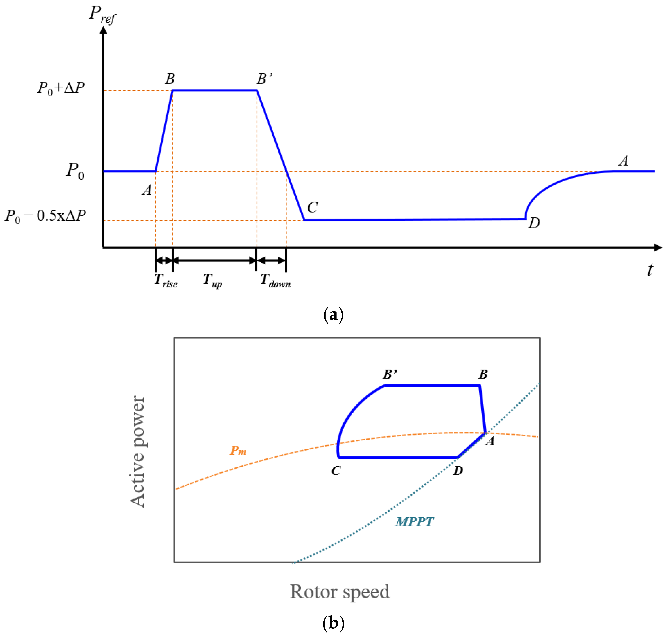
Recognizing the importance of SIC, transmission system operators (TSOs) have introduced explicit requirements in grid codes. The Hydro-Québec TransÉnergie (HQT) specification prescribes a four-phase response consisting of (i) a power boost, (ii) a short hold, (iii) a continuous ramp-down to an intermediate level, and (iv) a hold at a fixed power level, which is sustained until the operating point rejoins the MPPT curve [
22,
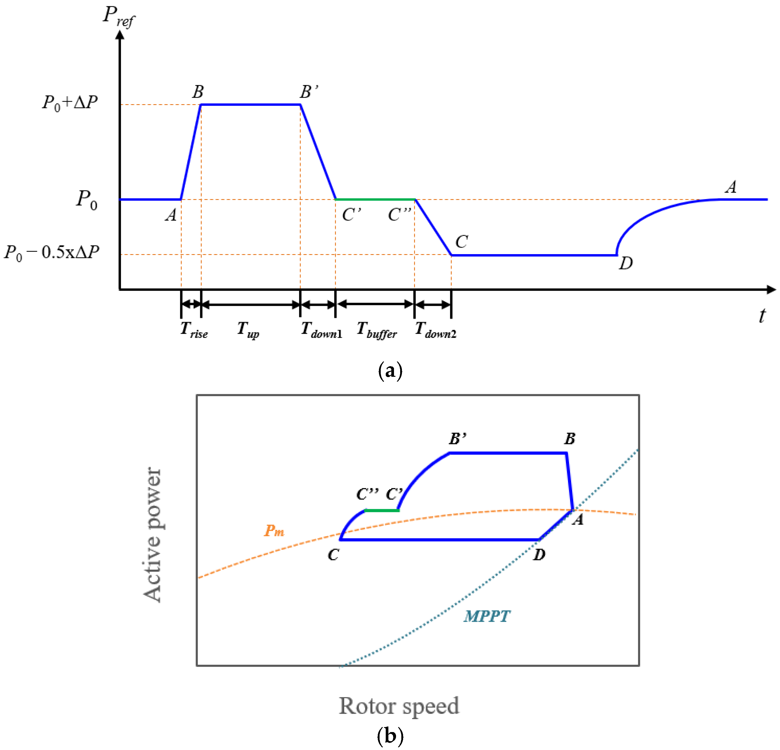
23]. In contrast, the ENTSO-E Nord Pool specification also forms a four-phase response but introduces a buffer stage within the ramp-down process, effectively splitting it into two segments [
24,
25]. While the additional buffer is intended to suppress further frequency decline, it entails extra kinetic-energy extraction and can aggravate rotor instability. Overall, both approaches embody a fundamental trade-off: a larger power boost strengthens the frequency nadir but also exacerbates an SFD and increases the risk of rotor OD. To avoid these risks, the boost must be constrained, which inherently limits SIC performance.
This paper proposes an enhanced SI requirement that builds on the structures of HQT and Nord Pool while addressing their limitations. The approach retains the stepwise boost-and-hold behavior common to both specifications but replaces the time-based recovery with a rotor-speed-dependent reduction in active power, thereby preventing OD and alleviating an SFD before smoothly returning to MPPT. The proposed requirement is validated using a detailed electromagnetic transient (EMTP) model of the Unison U151 wind turbine (4.569 MW, inertia constant 9.68 s), specifically designed for Korea’s low-wind conditions. Five case studies at wind speeds of 5 and 7 m/s with varying boost magnitudes are conducted to evaluate the effects of the proposed scheme on frequency nadir improvement, rotor stability, and kinetic energy utilization, providing a comprehensive comparison against existing grid-code-based requirements.
2. Modeling of PMSG-Based Wind Turbine Generator and Control System
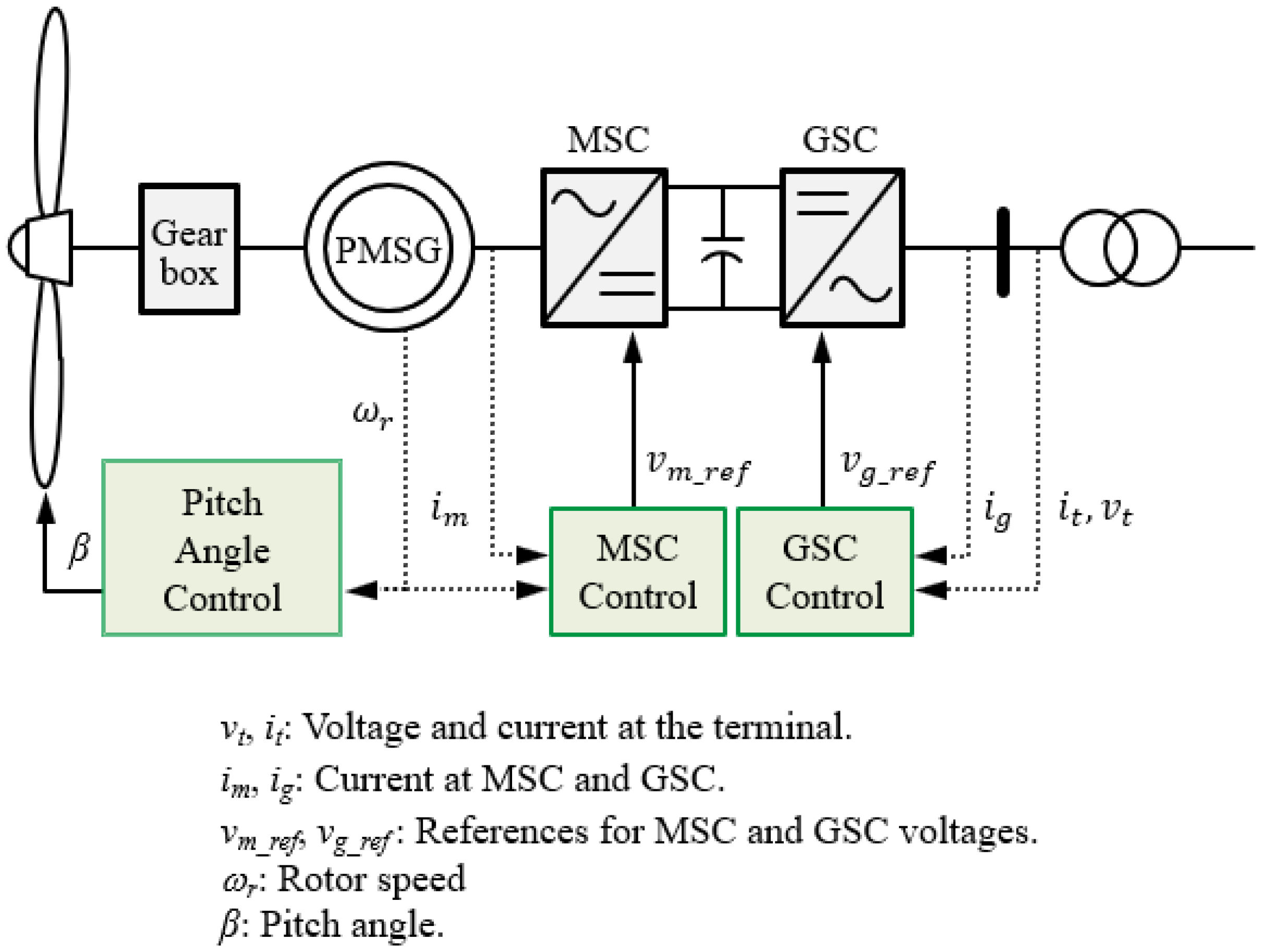
The overall structure of a permanent-magnet synchronous generator (PMSG)-based wind turbine generator (WTG) is illustrated in
Figure 1. The system consists of a wind turbine, a gearbox, a PMSG, a back-to-back converter, and associated control units. The mechanical dynamics of the drive train are modeled using a two-mass representation of the turbine and generator shafts. For the generator, a fifth-order representation in the dq synchronous reference frame is employed, which incorporates voltage and flux equations to accurately capture the electromagnetic dynamics [
26].
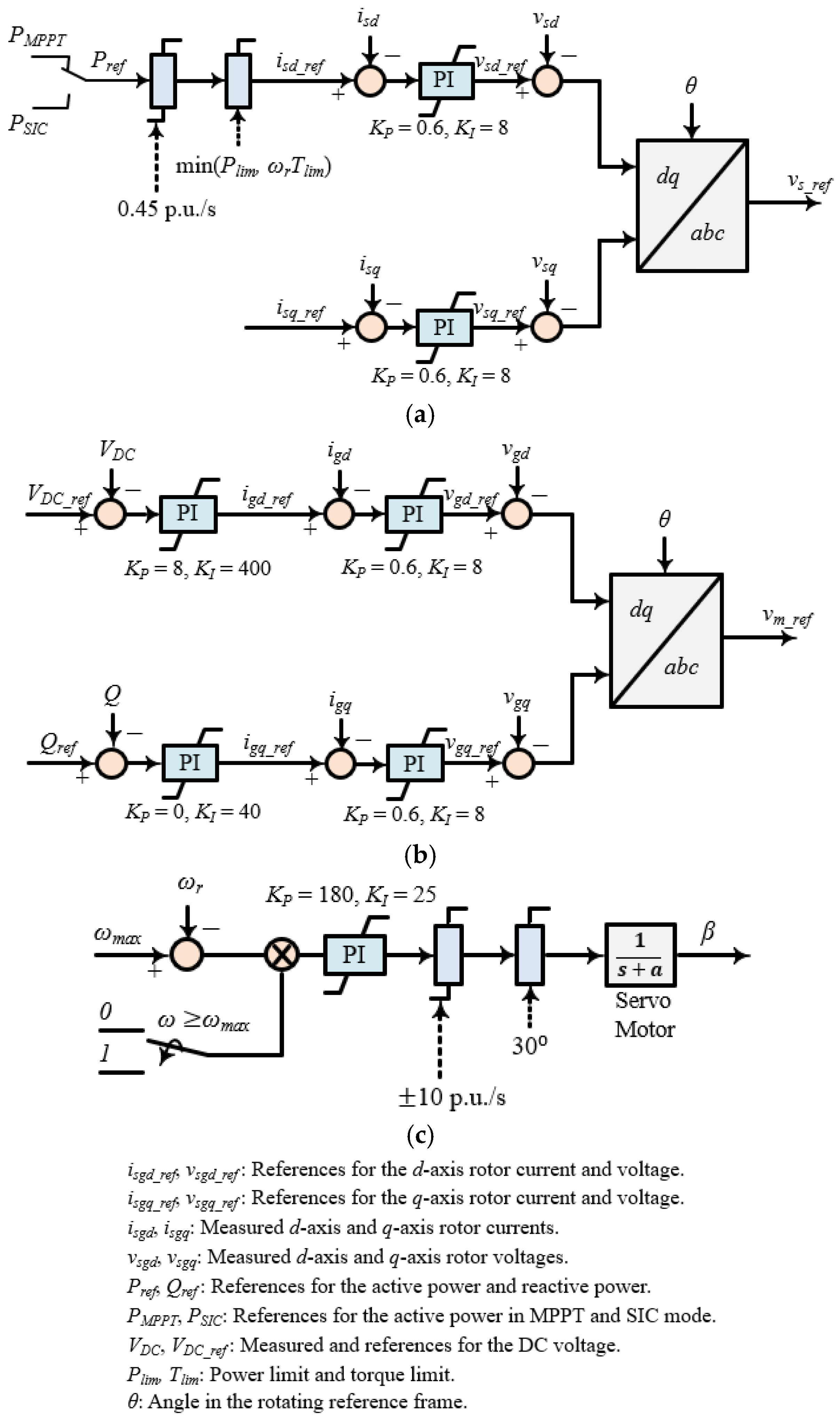
The control system is shown in
Figure 2, which includes controllers for the machine-side converter (MSC), the grid-side converter (GSC), and the pitch actuator. The MSC regulates the active power exchange between the generator and the grid, while the GSC is responsible for stabilizing the DC-link voltage and managing reactive power. The pitch-angle controller adjusts the blade pitch to ensure that the rotor speed (
) remains within its operational limits.
The reference active power during normal operation is determined by the MPPT strategy, expressed as
where
is the MPPT constant [
27].
When a frequency disturbance is detected, the active power reference
switches from MPPT operation (
) to SIC operation (
), as illustrated in
Figure 2a. Depending on the specific SIC scheme—described in
Section 3 and
Section 4—the turbine provides additional active power for a limited duration before smoothly returning to MPPT mode. The reference power is constrained by both a power rate limiter and a torque limiter. In this study, the power ramping rate is restricted to 0.45 p.u./s, and the maximum torque limit (
) is set to 1.0 p.u.
4. Proposed Synthetic Inertia Requirement
The comparison of HQT and Nord Pool requirements highlights a persistent trade-off between system-level frequency support and turbine-level rotor stability. While an initial power boost improves , it also accelerates rotor deceleration, making successful recovery contingent on the operating point falling below the curve. In practice, this condition becomes increasingly difficult to satisfy as increases, thereby increasing the risk of OD.
The Nord Pool specification attempts to mitigate further frequency decline by introducing a buffer stage, which temporarily stabilizes power output and improves system-level recovery. However, this modification exacerbates rotor deceleration and further increases the likelihood of OD compared with HQT. Consequently, both approaches reveal an inherent trade-off: they enhance frequency recovery at the grid level but at the expense of turbine stability.
To address these shortcomings, this paper proposes an enhanced SI requirement that retains the boosting benefits of HQT and Nord Pool while introducing a rotor-speed-dependent recovery mechanism. By reducing active power proportionally to rotor speed and transitioning smoothly back to MPPT, the proposed method aims to prevent OD, alleviate the second frequency dip, and improve overall system performance.
4.1. Proposed Control Profile
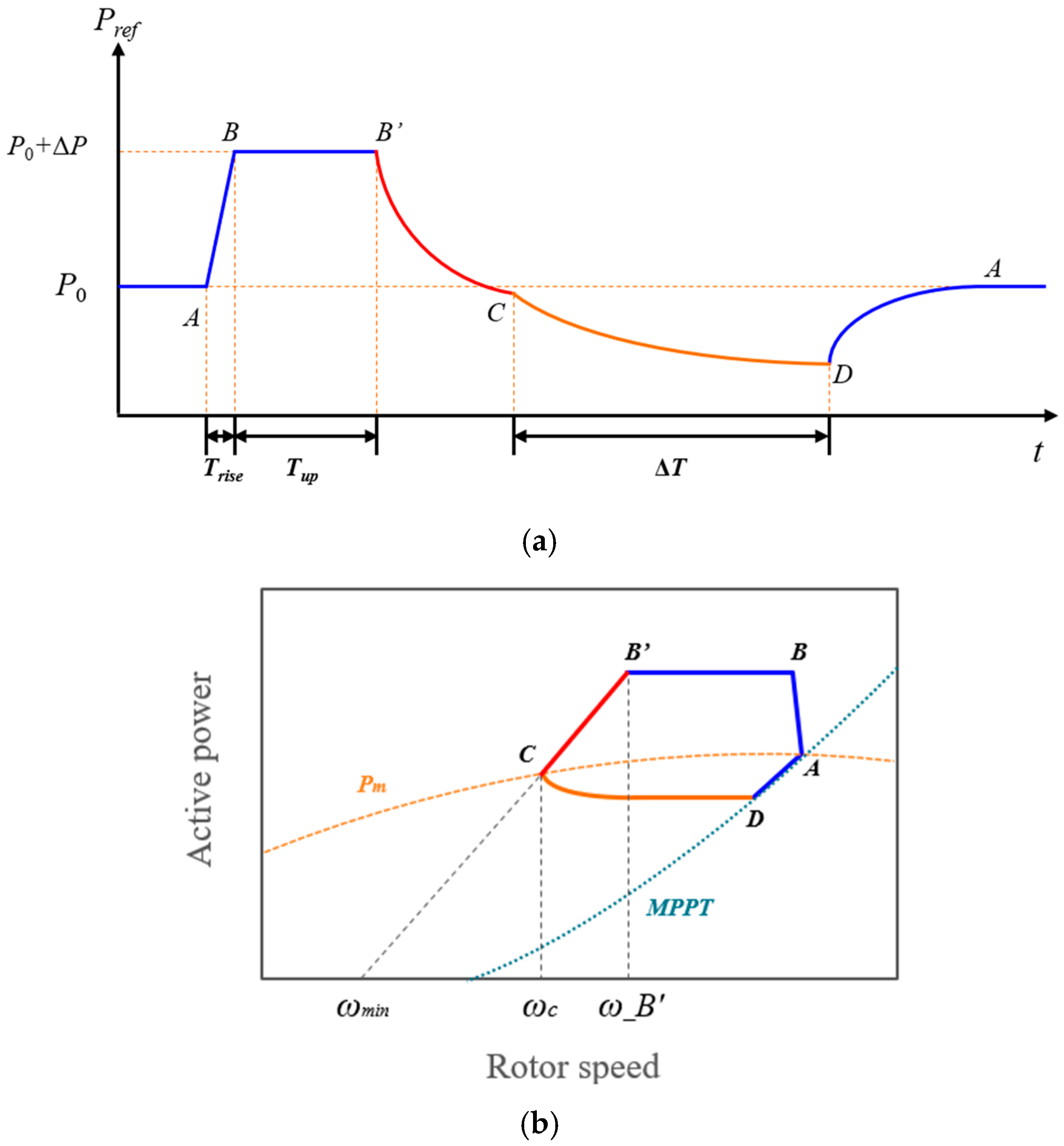
The proposed SI requirement is designed to preserve the beneficial characteristics of stepwise schemes while overcoming their inherent drawbacks. As shown in
Figure 5a,
follows the same boost-and-hold sequence (A–B–B′) as in the HQT and Nord Pool specifications. This structure is retained because the stepwise power boost is the essential feature of synthetic inertia schemes, ensuring a rapid improvement in
.
The key innovation lies in the recovery stage. Instead of applying a purely time-based ramp-down,
is reduced proportionally to rotor speed during B′–C. In this interval,
is defined as
where
is the minimum stable rotor speed.
This rotor-speed-dependent decrease prevents the electrical torque from exceeding the aerodynamic torque during the recovery process, thereby avoiding OD while simultaneously reducing the magnitude of an SFD.
Once rotor speed stabilizes, the trajectory transitions smoothly from point C to D, enabling a gradual return to MPPT operation. The transition is expressed as
where
is the duration for transition to MPPT;
is the time when
stabilizes;
is the difference between
and
[
17].
The overall profile is illustrated in
Figure 5a, while the corresponding power–rotor speed trajectory is shown in
Figure 5b, demonstrating how the proposed method alleviates OD and supports stable system recovery.
4.2. Power-Rotor Speed Trajectory Analysis
The dynamic behavior of the proposed requirement can be further understood through the power–rotor speed trajectory shown in
Figure 5b. During the boost-and-hold stage (A–B–B′),
exceeds the
curve, causing the electrical torque to surpass the aerodynamic torque and leading to rotor deceleration. This phenomenon is common to all stepwise SI schemes, including those specified by HQT and Nord Pool.
The distinction arises during the recovery process (B′–C). In the proposed approach, decreases proportionally with rotor speed, converging to the curve. Point C represents the equilibrium point on the curve, where the aerodynamic and electrical torques are equal. At this equilibrium, rotor speed can begin to recover without entering an OD condition. By contrast, the HQT and Nord Pool schemes employ time-based reductions, making it difficult to guarantee that point C lies below the curve, particularly for large .
After stabilization at point C, the transition from point C to D provides a gradual reduction in , enabling the operating point to realign smoothly with the MPPT curve. This gradual recovery prevents abrupt torque reversals, thereby alleviating an SFD while preserving rotor stability.
Overall, the trajectory analysis demonstrates that the proposed scheme balances system-level frequency support and turbine-level stability: it achieves the same initial nadir improvement as HQT and Nord Pool, while avoiding OD and mitigating an SFD through rotor-speed-dependent recovery.
6. Case Studies
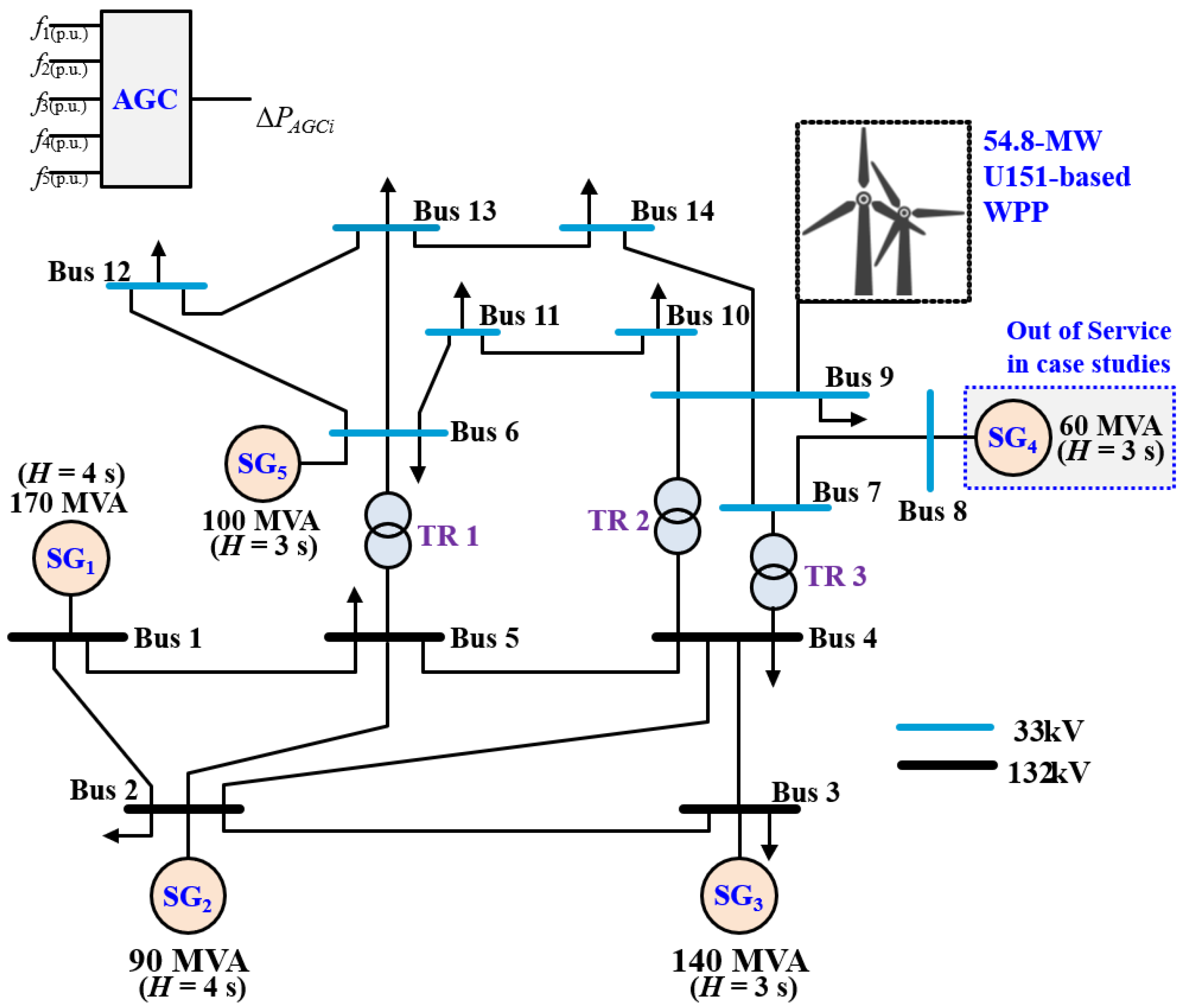
To evaluate the effectiveness of the proposed SI requirement, a series of case studies were performed using the test system described in
Section 5. In each case, a frequency event was triggered by tripping SG
2 (36 MW) at
t = 10 s. The resulting system response was analyzed under three control strategies: the HQT specification, the ENTSO-E Nord Pool specification, and the proposed requirement.
The studies were designed to examine how wind speed and the magnitude of influence frequency support and rotor stability. Two operating points were selected to represent different levels of available kinetic energy. At a wind speed of 5.0 m/s, the initial rotor speed was approximately 0.679 p.u., corresponding to a relatively limited energy reserve. At a higher wind speed of 7.0 m/s, a larger kinetic energy margin was available, allowing for more aggressive SIC operation.
In this section, and are set to 1 s, 10 s, 2 s, 1 s, 10 s, and 45 s, respectively.
Across these wind speeds, the power boost magnitude varied systematically: = 10% and 60% at 5.0 m/s, and = 10%, 40%, and 60% at 7.0 m/s. This framework enables a direct comparison of the proposed scheme with existing grid-code requirements under conditions ranging from low to moderate kinetic energy availability.
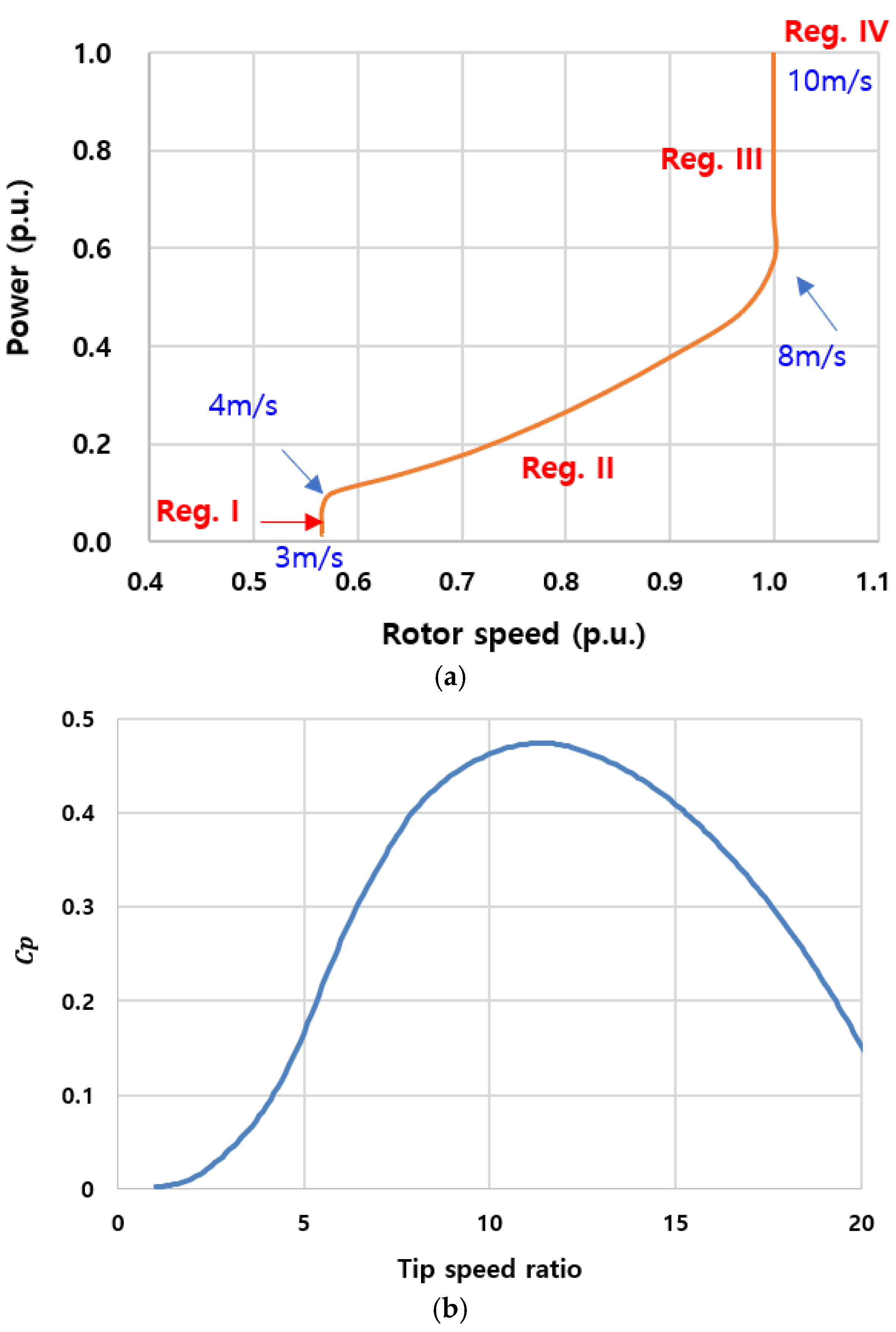
The selection of 5.0 m/s and 7.0 m/s was based on their representativeness within the MPPT region (Region II). A wind speed of 5.0 m/s corresponds to conditions with limited available kinetic energy, allowing us to demonstrate the proposed method’s effectiveness under constrained reserves, whereas 7.0 m/s represents a moderate-wind condition with larger kinetic energy margins for more aggressive support. Region III cases (e.g., 9.0 m/s) were not included, as they involve additional control mechanisms beyond pure synthetic inertia and could dilute the focus of this study.
The simulation objectives are threefold: (i) to assess improvements in , (ii) to evaluate the extent of an SFD, and (iii) to determine the potential for OD. Together, these metrics provide a comprehensive view of how effectively each SI scheme balances system-level frequency support with turbine-level stability.
6.1. Case 1: Wind Speed of 5.0 m/s and of 10%
Figure 8 presents the simulation results for Case 1, where the wind speed is 5.0 m/s and
is set to 10% of the pre-event output. As summarized in
Table 2,
was identical across all three SI schemes (HQT, Nord Pool, and the proposed requirement), since
was fixed at the same level. Nevertheless, all SI-based schemes improved the nadir by approximately 0.016 Hz compared with the MPPT case (59.536 Hz vs. 59.520 Hz). This modest gain underscores that while the effect of SI is limited at small
, its benefits become more evident as the boost level increases, a point further explored in subsequent cases.
The more critical difference appears in the second nadir, which reflects the severity of the SFD. Among the schemes, the proposed scheme achieved the highest second nadir (59.810 Hz), compared with 59.806 Hz for Nord Pool and 59.801 Hz for HQT. This confirms that the rotor-speed-dependent recovery strategy of the proposed method effectively alleviates the SFD, even under low wind speed and small boost conditions.
Rotor speed trajectories in
Figure 8d show that the rotor speed decreased to 0.636 p.u. under the proposed scheme, compared with 0.642 p.u. for HQT and Nord Pool. As a result, the proposed requirement released more kinetic energy (23% of the available reserve) than HQT and Nord Pool (both 16%), contributing directly to its improved second nadir.
It is also noteworthy that the Nord Pool scheme, despite introducing a buffer stage, released nearly the same amount of energy as HQT. This outcome is attributable to the high inertia constant of the U151 turbine (H = 9.68 s). At 5 m/s with a small boost ( = 10%), the turbine can sustain a higher second nadir without requiring additional energy extraction than the HQT. In other words, for high-inertia turbines operating under low-wind conditions, Nord Pool achieves better mitigation of the SFD than HQT while maintaining comparable energy utilization.
Overall, Case 1 demonstrates that while the absolute improvement in frequency nadir is modest due to the small , the proposed requirement outperforms both HQT and Nord Pool in mitigating the SFD and preventing OD, highlighting its robustness even under limited kinetic energy conditions.
6.2. Case 2: Wind Speed of 5.0 m/s and of 60%
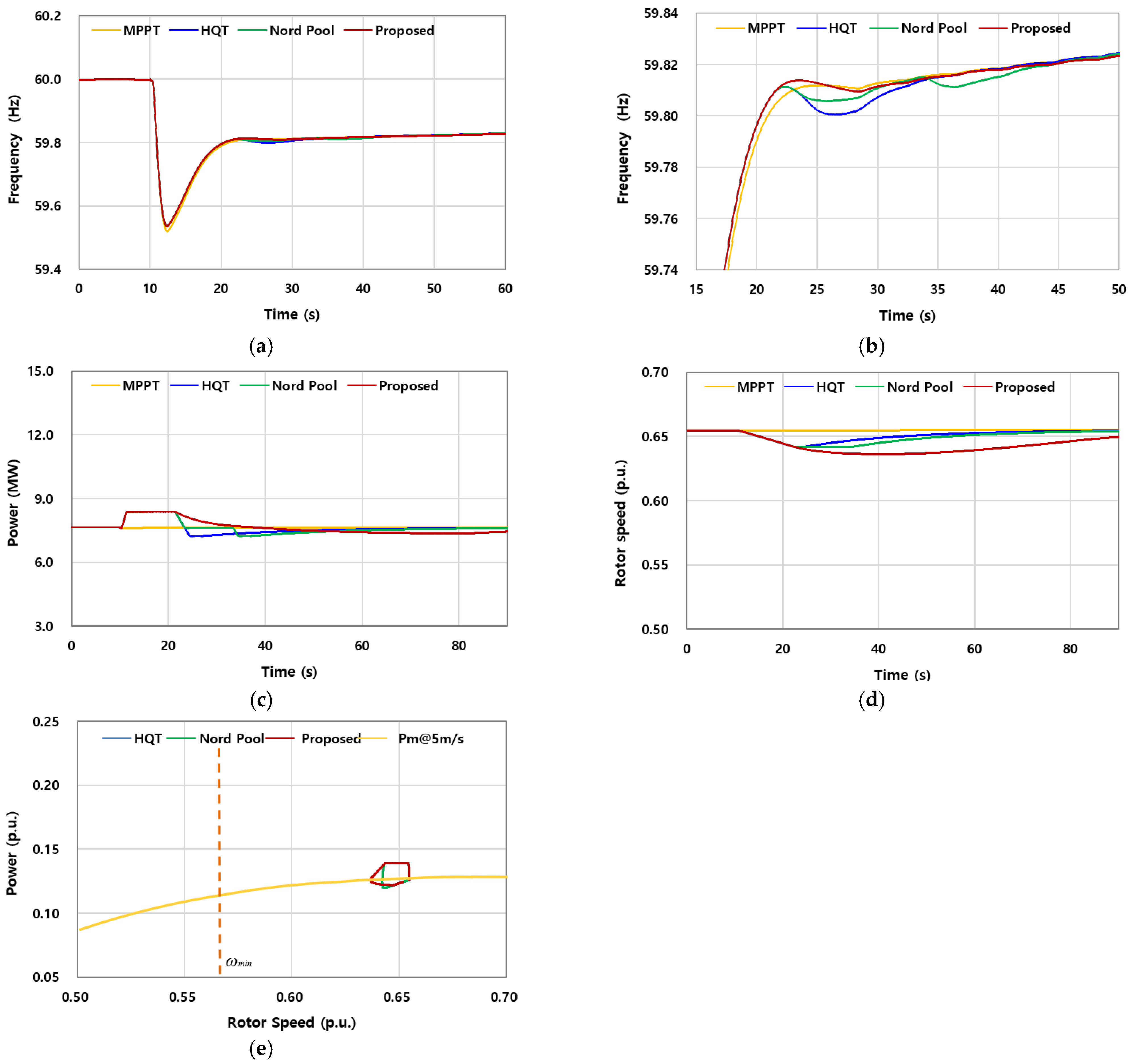
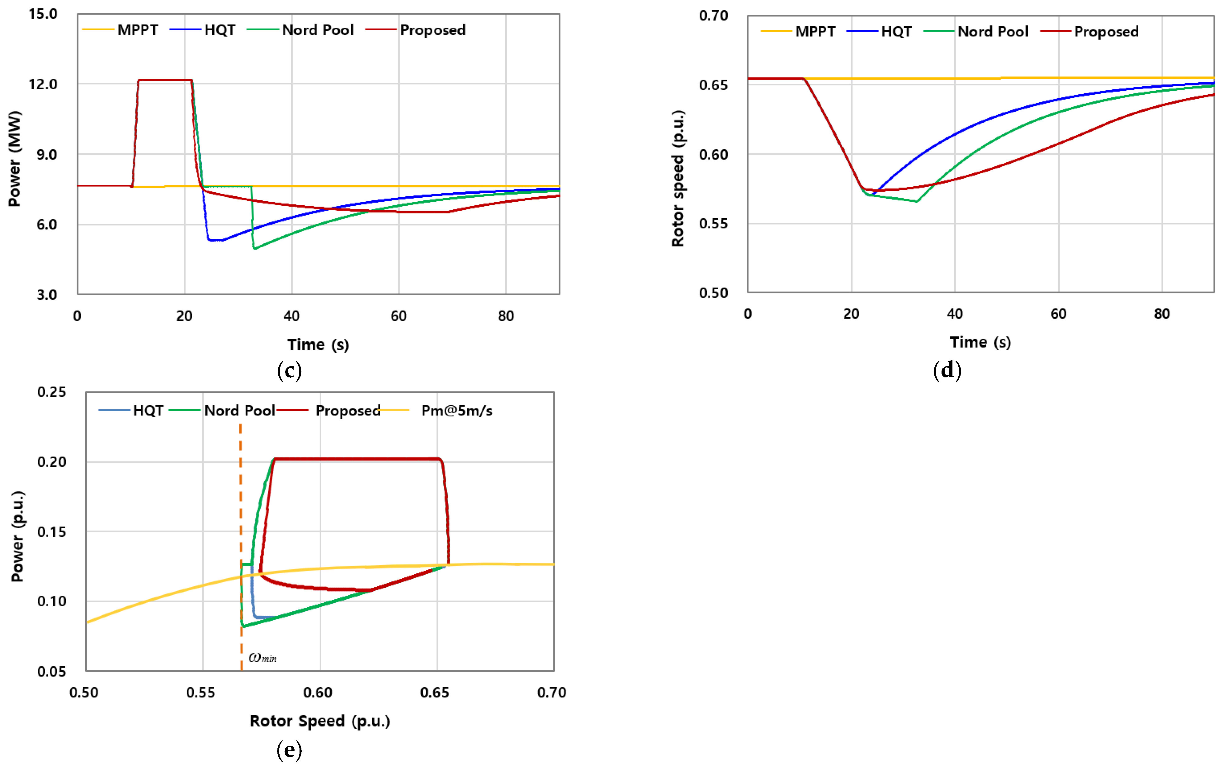
To evaluate the upper bound of SIC capability for the U151 turbine under low-wind conditions, was progressively increased from 10% of the pre-event output until OD was observed. The objective was to identify the maximum boost level that could be sustained without compromising rotor stability, even under demanding SIC operation. Notably, rotor instability appeared earlier than expected: at = 60%, OD occurred in the Nord Pool profile, whereas the HQT and the proposed requirement avoided OD under the same condition.
Figure 9 illustrates the results for Case 2, where
is six times greater than in Case 1. This setup enables a more comprehensive assessment of the U151’s performance and the comparative effectiveness of the three SIC strategies.
As summarized in
Table 2, all three SI schemes achieved the same first nadir (59.607 Hz), corresponding to an improvement of 0.087 Hz relative to the MPPT case (59.520 Hz). This confirms the direct effect of the larger
: while Case 1 improved the nadir by only 0.016 Hz, Case 2 yielded a substantially greater enhancement, equivalent to a 17% reduction in nadir deviation.
The second nadir provides clearer insight into scheme-dependent performance. The proposed requirement delivered the best result (59.773 Hz), slightly outperforming HQT (59.746 Hz) and Nord Pool (59.7725 Hz). However, in the Nord Pool case, this improvement came at the expense of rotor stability: OD was observed, driven by the buffer stage that prolongs energy extraction beyond the turbine’s aerodynamic torque balance. In
Figure 9e, this instability is evident during the buffer period. Once OD occurred,
was forced to switch back to the MPPT curve, leading to an abrupt reduction in active power output. This sudden drop in power aggravated the system response, producing an additional frequency decline and thereby manifesting as a pronounced subsequent frequency dip.
Rotor speed responses in
Figure 9d show the minimum rotor speed dropped to 0.571 p.u. under HQT, 0.566 p.u. under Nord Pool, and 0.574 p.u. under the proposed scheme. The Nord Pool trajectory exhibited the deepest deceleration, consistent with OD. The released energy values in
Table 2 also support this interpretation: Nord Pool extracted 100% of the available kinetic energy, compared with 95% for HQT and 92% for the proposed method. By contrast, the proposed scheme mitigated the SFD with less extreme energy depletion, preserving a safer operating margin.
In summary, Case 2 demonstrates that at a wind speed of 5 m/s, the U151 turbine can sustain large boosts without instability when operated under HQT or the proposed requirement. However, OD emerges in the Nord Pool profile at = 60%, indicating that its buffer strategy can become counterproductive under high-boost conditions. The proposed requirement not only matched the nadir improvements of existing grid-code-based schemes but also maintained rotor stability and alleviated the SFD with less energy extraction, underscoring its advantage under demanding SIC scenarios.
6.3. Case 3: Wind Speed of 7.0 m/s and of 10%
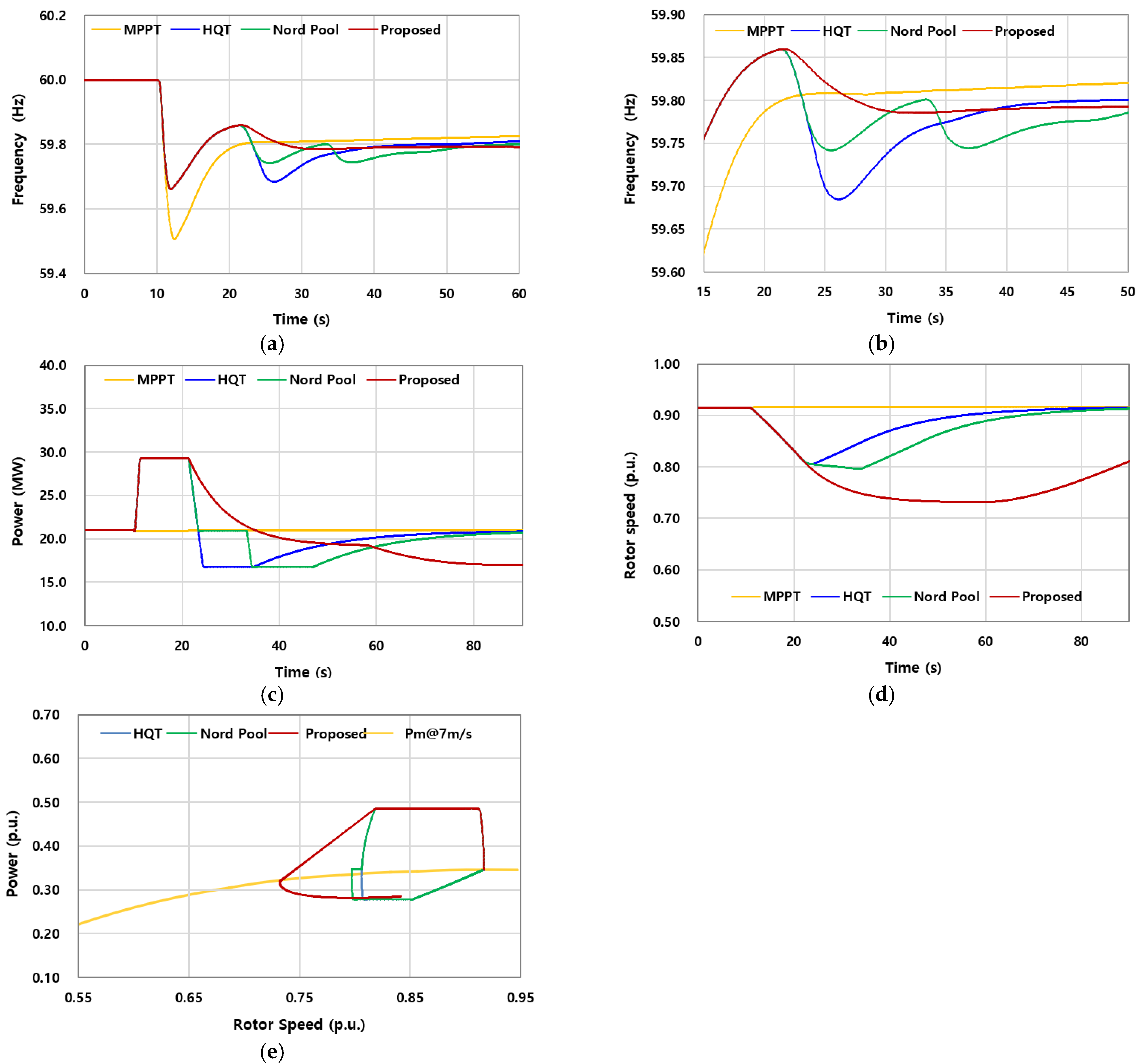
Figure 10 summarizes the results for Case 3, where the wind speed was increased to 7 m/s while maintaining a boost of
= 10% of the pre-event output. Similar to Case 1, all three SI schemes (HQT, Nord Pool, and the proposed method) achieved the same improvement in the first frequency nadir relative to MPPT, raising it from 59.507 Hz to 59.552 Hz (
Table 2). This corresponds to a modest enhancement of 0.045 Hz compared with MPPT.
The key distinction at this higher wind speed is the larger amount of releasable kinetic energy. As shown in
Figure 10d, the rotor maintained a significantly higher pre-event speed (0.891 p.u.), ensuring a substantial energy reserve. However, since the boost level was kept at only 10%, the actual extracted energy remained small: approximately 9% for HQT and Nord Pool, and 19% for the proposed scheme (
Table 2). This explains why the nadir improvement was limited despite the higher energy availability.
Regarding the second nadir, the proposed method once again demonstrated a noticeable advantage. The extended frequency response in
Figure 10b indicates that the proposed scheme achieved 59.812 Hz, outperforming both HQT (59.777 Hz) and Nord Pool (59.790 Hz). This improvement is attributable to the rotor-speed-dependent recovery, which alleviates over-deceleration and mitigates the SFD, even under low boost conditions.
In summary, Case 3 confirms that when is small, the high inertia of the U151 turbine prevents significant rotor instability across all schemes. Nonetheless, the proposed method consistently maintains the highest second nadir, highlighting its robustness in reducing SFD while operating safely at higher wind speeds.
6.4. Case 4: Wind Speed of 7.0 m/s and of 40%
Figure 11 presents the results for Case 4, where
was increased to 40% at a wind speed of 7 m/s. Compared with Case 3, the larger boost delivered more significant frequency support immediately after the event, raising the first nadir well above that of MPPT. However, the recovery dynamics revealed clear differences among the schemes.
In the Nord Pool specification, a severe third frequency dip appeared during the recovery stage. This was not due to OD but rather a consequence of the buffer stage. When the buffer interval ended, the subsequent reduction of
was applied over a much larger
than in Case 3. The sharper decline in active power output produced a noticeable drop in system frequency, creating the pronounced third frequency dip observed in
Figure 11b. This demonstrates that while the buffer temporarily slows frequency decay, it also amplifies the magnitude of the later reduction when
is large.
The HQT scheme, which applies a continuous ramp-down instead of a buffer, showed a more moderate SFD but released less kinetic energy overall. By contrast, the proposed method injected more energy than either HQT or Nord Pool while ensuring that the reduction of was governed by rotor speed. As a result, rotor deceleration remained within stable limits, OD was avoided, and the second nadir was higher than in both grid-code schemes.
These results confirm that at higher boost levels, Nord Pool’s buffer strategy can aggravate frequency instability, whereas the proposed rotor-speed-dependent recovery provides more effective support without introducing new dips, striking a superior balance between frequency improvement and rotor stability.
6.5. Case 5: Wind Speed of 7.0 m/s and of 60%
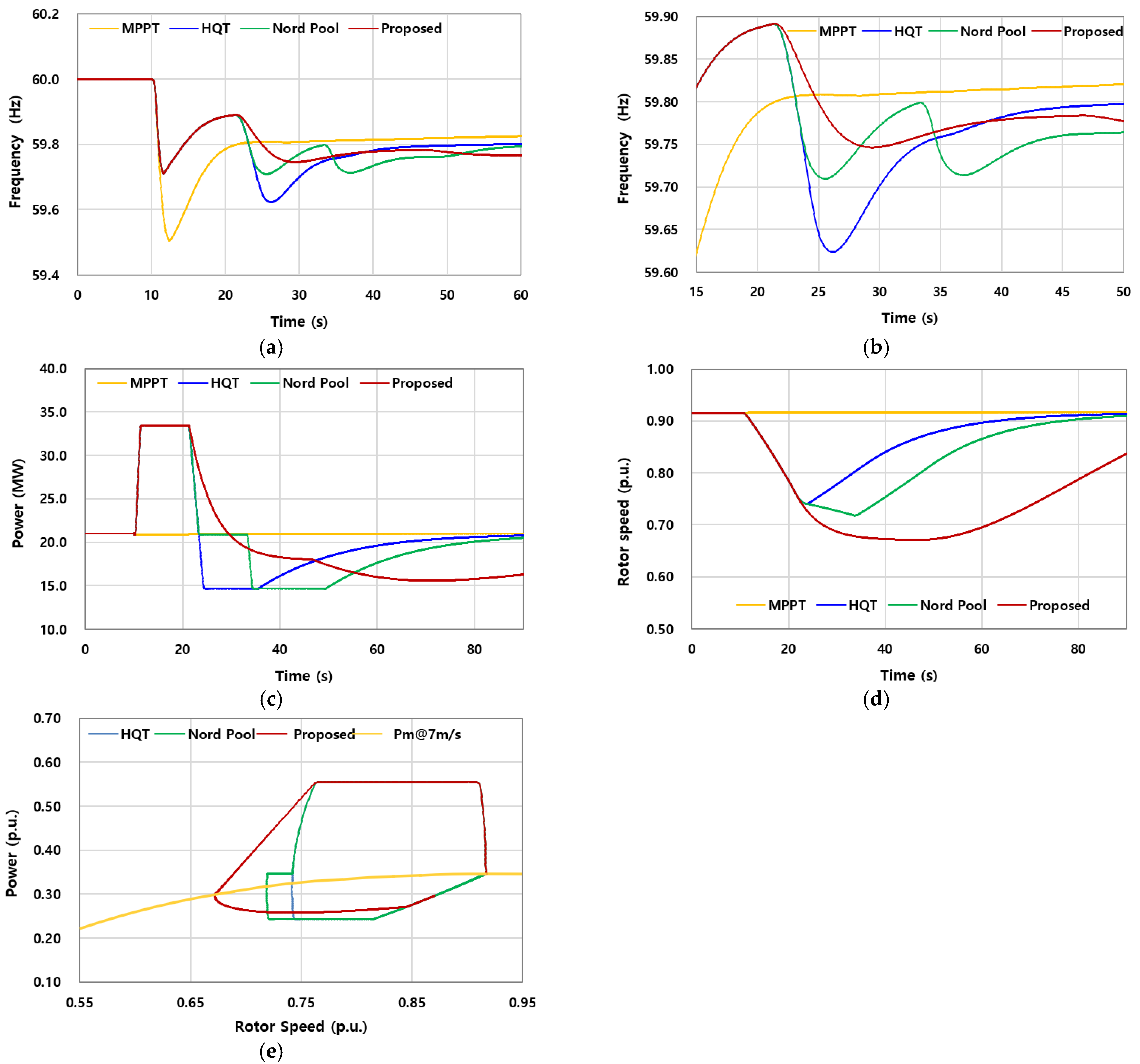
Figure 12 summarizes the results for Case 5, where the boost magnitude was increased to 60% at a wind speed of 7 m/s. Under this condition, all SIC strategies improved the first nadir compared with MPPT, but clear weaknesses appeared in the recovery stage.
For the HQT profile, the second nadir fell below the first. This outcome was not due to rotor instability but rather to the steep ramp-down applied after the boost. The large forced an abrupt reduction in active power, which in turn caused the system frequency to decline more sharply, producing a deeper SFD than in the initial dip.
The Nord Pool profile exhibited a different response. The buffer stage delayed the initial reduction, leading to a second nadir that was slightly lower than the first. When the subsequent ramp-down was applied, a third nadir appeared, which remained higher than the first nadir but close in depth to the second. This pattern shows that while the buffer helps to avoid a sharp immediate drop, it is unable to fully prevent repeated dips when the boost magnitude is large.
By contrast, the proposed rotor-speed-dependent strategy achieved a smoother and more stable recovery trajectory. Because was reduced in proportion to rotor speed, the scheme avoided sharp torque imbalances and prevented the cascading nadirs observed in HQT and Nord Pool. As a result, the proposed requirement maintained rotor stability, alleviated the SFD, and achieved the highest second nadir among all cases.
Overall, Case 5 confirms that conventional grid-code-based schemes struggle to manage large boosts, either deepening the second nadir (HQT) or producing repeated dips (Nord Pool). The proposed method, however, demonstrated robust performance under the same conditions, highlighting its suitability for future grid-code applications in low-inertia systems.
Table 2 summarizes the results of all five case studies, reporting the first and second frequency nadirs, the relative improvement in frequency nadir compared with the MPPT baseline, the minimum rotor speed, and the proportion of released kinetic energy. These indicators provide a concise comparison of SIC performance across MPPT, HQT, Nord Pool, and the proposed scheme, serving as the basis for evaluating trade-offs between frequency support and rotor stability.
Table 2.
Comparative results for all cases.
Table 2.
Comparative results for all cases.
| Cases | Control Schemes |
(Hz) |
(Hz) | Improvement vs. MPPT (%) | 2nd
(Hz) | Min.
(p.u.) | Released Energy
(%) |
|---|
| 1 | MPPT | 59.520 | 0.480 | - | - | 0.655 | - |
| HQT | 59.536 | 0.464 | 3.3 | 59.801 | 0.642 | 16 |
| Nord Pool | 59.536 | 0.464 | 3.3 | 59.806 | 0.642 | 16 |
| Proposed | 59.536 | 0.464 | 3.3 | 59.810 | 0.636 | 23 |
| 2 | MPPT | 59.520 | 0.480 | - | - | 0.655 | - |
| HQT | 59.607 | 0.393 | 18.1 | 59.746 | 0.571 | 95 |
| Nord Pool | 59.607 | 0.393 | 18.1 | 59.7725 | 0.566 | 100 |
| Proposed | 59.607 | 0.393 | 18.1 | 59.773 | 0.574 | 92 |
| 3 | MPPT | 59.507 | 0.493 | - | - | 0.916 | - |
| HQT | 59.552 | 0.448 | 9.1 | 59.777 | 0.891 | 9 |
| Nord Pool | 59.552 | 0.448 | 9.1 | 59.790 | 0.891 | 9 |
| Proposed | 59.552 | 0.448 | 9.1 | 59.812 | 0.862 | 19 |
| 4 | MPPT | 59.507 | 0.493 | - | - | 0.916 | - |
| HQT | 59.662 | 0.338 | 31.4 | 59.685 | 0.775 | 37 |
| Nord Pool | 59.662 | 0.338 | 31.4 | 59.742 | 0.760 | 39 |
| Proposed | 59.662 | 0.338 | 31.4 | 59.777 | 0.700 | 58 |
| 5 | MPPT | 59.507 | 0.493 | - | - | 0.916 | - |
| HQT | 59.713 | 0.287 | 41.8 | 59.624 | 0.741 | 56 |
| Nord Pool | 59.713 | 0.287 | 41.8 | 59.710 | 0.719 | 62 |
| Proposed | 59.713 | 0.287 | 41.8 | 59.747 | 0.672 | 75 |
7. Conclusions
This paper investigated synthetic inertia requirements for wind turbine generators by examining established grid-code specifications and proposing an improved alternative. Building on the HQT and ENTSO-E Nord Pool approaches, the study introduced a rotor-speed-dependent recovery strategy designed to overcome the limitations of time-based reductions. The Unison U151 wind turbine, developed for Korea’s low-wind conditions, was modeled to validate the feasibility of the approach, leveraging its large inertia constant to provide effective frequency support.
The comparative analysis of SI requirements highlighted the inherent trade-offs in existing schemes. The HQT specification, which employs a continuous ramp-down, is prone to deeper SFDs when the boost magnitude is large due to rapid power reduction. The Nord Pool specification, by inserting a buffer stage, alleviates some of these issues but often produces repeated nadirs under heavy boosts. In contrast, the proposed requirement maintained the benefits of stepwise boosting while mitigating OD and alleviating an SFD, resulting in a smoother recovery trajectory and higher stability margins.
The case studies across five scenarios, varying in wind speed and boost magnitude, confirmed the robustness of the proposed method. While all schemes improved the first nadir relative to MPPT, only the proposed requirement consistently sustained a higher second nadir and stable rotor dynamics. At moderate boosts, it released more kinetic energy without instability, and at high boosts, it prevented the severe dips observed in both HQT and Nord Pool. These results underscore the potential of combining high-inertia turbines, such as the U151, with rotor-speed-dependent SI schemes to strengthen frequency stability in low-inertia systems. From a policy perspective, these findings suggest that current grid-code requirements, exemplified by HQT and Nord Pool, could be improved by integrating rotor-speed-dependent recovery strategies. Such an update would allow TSOs and regulators to better balance frequency security with turbine protection, thereby enhancing the reliability of future power systems with high renewable penetration.
