1. Introduction
The penetration of renewable energy sources and power electronic devices in modern power systems continues to grow [
1,
2]. However, renewable energy sources, such as photovoltaic, wind, and ocean energy [
3], are highly dependent on natural conditions, resulting in high intermittency and volatility. This significantly increases the complexity of grid operation [
4,
5], thereby driving the need for energy storage systems to perform peak shaving and valley filling [
6,
7]. Among various storage technologies, the GESS has attracted growing attention worldwide in recent years [
8,
9,
10] due to its capability for reversible conversion between gravitational potential energy and electrical energy. Compared with other storage methods, the GESS is less susceptible to environmental fluctuations, demonstrates high stability and reliability, offers a long service life, and entails relatively low maintenance costs.
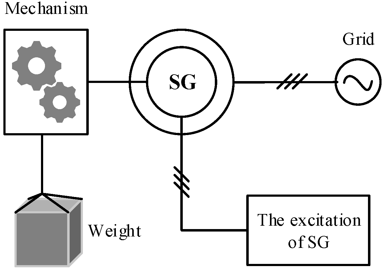
Existing GESS architectures are predominantly based on synchronous generators [
11,
12,
13], as illustrated in
Figure 1. Nevertheless, these designs face several critical limitations. On the one hand, since the rotor speed of a synchronous generator must remain strictly locked to the grid frequency, the translational velocity of the weight block cannot be controlled independently. On the other hand, the active power delivered to the grid can only be adjusted by engaging or disengaging discrete weights, a method that is inherently inflexible and lacks diversity in control strategies.
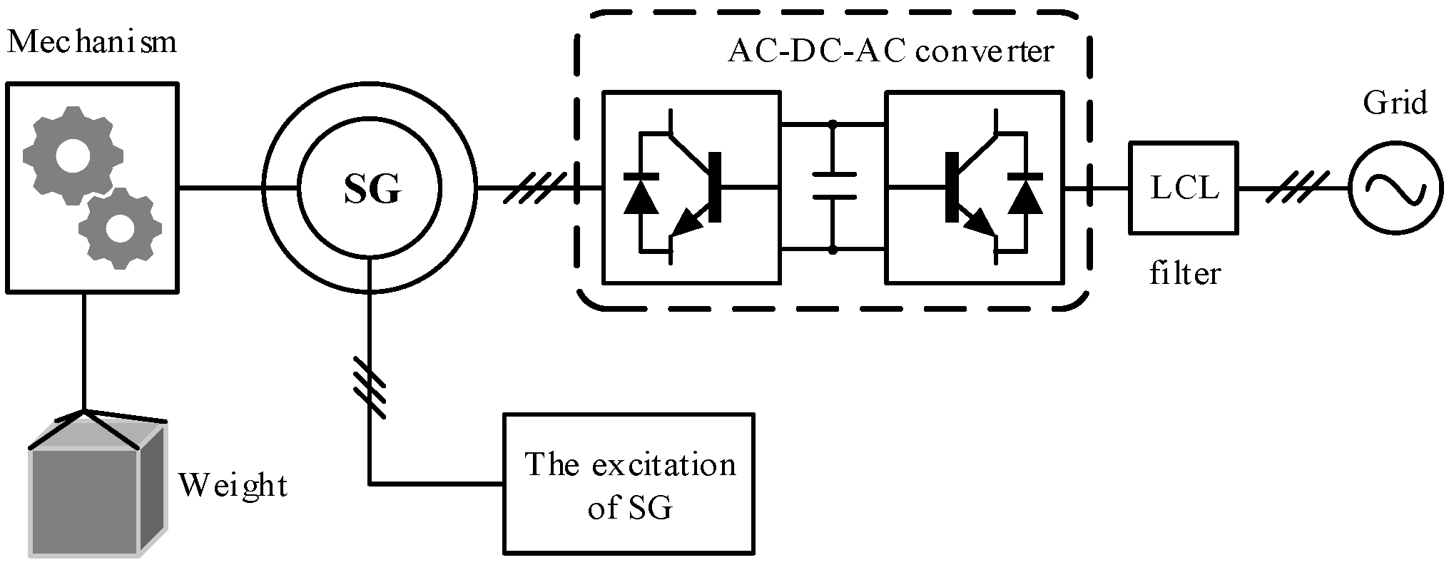
An alternative approach [
10,
14], shown in
Figure 2, connects the stator of the synchronous generator to the load or grid through an AC-DC-AC converter. In this configuration, the stator voltage is rectified to DC by the generator-side converter and then inverted to grid-synchronized AC power by the grid-side converter (GSC). This arrangement eliminates the strict requirement for rotor speed to match the grid frequency, enabling wide-range control of the weight block velocity. However, in GESS architectures that employ an AC-DC-AC converter, the converter must be rated for the full power of the gravity storage system. Consequently, the need for a high-power converter leads to increased manufacturing and maintenance costs.
Unlike synchronous generators, the rotor speed of a DFIG is not synchronized with the stator frequency. By regulating power through the rotor-side converter (RSC), DFIGs can achieve variable-speed constant-frequency (VSCF) operation. Since the converter is connected to the rotor side, its power rating is only a fraction of the generator’s rated power. This partial-scale converter significantly reduces the system cost, representing a clear advantage for GESS applications [
15]. Nevertheless, research on DFIG-GESS remains limited. Compared to synchronous generators, DFIGs have lower rotational inertia and thus weaker grid-support capability [
16]. To address this issue, Ref. [
17] emulates the primary active power-frequency droop characteristic of synchronous generators to provide grid support. More broadly, recent studies on grid support mainly focus on strategies such as droop control [
18], virtual synchronous generator (VSG) control [
16], virtual oscillator control (VOC) [
19], and matching control [
20].
In [
21] a small-signal model of multiple DFIGs is developed, focusing on the DC-link voltage control dynamics (around 10 Hz). The model reveals mutual interactions among grid-following DFIGs due to terminal voltage coupling under weak grid conditions, as well as the mechanism by which closely matched phase-locked loop (PLL) bandwidths in different units reduce the damping of the dominant mode and can lead to system instability. Ref. [
22] develops a small-signal electromechanical model of grid-forming (GFM) controlled DFIG-based wind turbines under weak grid conditions. It identifies their vulnerability to electromechanical oscillations and proposes a hybrid d-q axis voltage reference drivetrain damping control strategy to ensure stable operation. Ref. [
23] introduces an adaptive droop control method based on the rate of change of frequency (ROCOF). This method allows the DFIG to dynamically adjust its control coefficients according to system dynamics during frequency support, thereby significantly improving the frequency nadir and mitigating the ROCOF. Ref. [
24] investigates the impact of inertial and primary frequency support from DFIG-based wind turbines on power system small-signal stability. The results demonstrate that while primary frequency support enhances the damping of electromechanical oscillations, the effectiveness of the inertial response is highly dependent on control parameters. Ref. [
25] proposes a DFIG frequency support control strategy based on kinetic energy release. This strategy rapidly releases the stored kinetic energy of the wind turbine rotor during sudden grid frequency drops, providing both inertia and primary frequency support while ensuring the safe operation of the turbine. However, these DFIG-based GFM strategies are primarily designed for wind power applications, where the control objective is power regulation. In contrast, research on GFM control is specifically tailored for GESS, where speed regulation is the primary objective, remains limited. Comparisons between the proposed method and the existing GFM methods have been listed in
Table 1.
This paper proposes the novel application of a DFIG in the context of a GESS. Although DFIGs have been widely studied in wind turbine applications, their use in gravity energy storage systems is relatively unexplored. The key challenge of applying DFIGs to a GESS lies in overcoming their low rotational inertia and limited grid support capability. Traditional control strategies designed for wind turbines may not be directly applicable in this context due to the unique operational characteristics of gravity-based storage systems.
The speed-adaptive droop control strategy introduced in this study aims to address these challenges by dynamically adjusting the droop curve in response to changes in rotor speed, enabling improved grid support while minimizing the power converter rating. This control method is not only an adaptation of known wind turbine control strategies but also offers distinct advantages for gravity energy storage applications, including more flexible energy conversion and a significant reduction in the power converter size.
The proposed strategy aims to (i) achieve inner-loop regulation of the weight’s translational speed using a partial-scale converter and (ii) enhance the system’s grid-support capability. The remainder of this paper is organized as follows.
Section 2 outlines the DFIG-GESS architecture and presents its mathematical model.
Section 3 details the derived RSC control strategy from the model.
Section 4 validates the proposed strategy through comprehensive MATLAB/Simulink simulations under various operating conditions. Finally,
Section 5 concludes the paper.
2. Structure and Modeling of DFIG-GESS
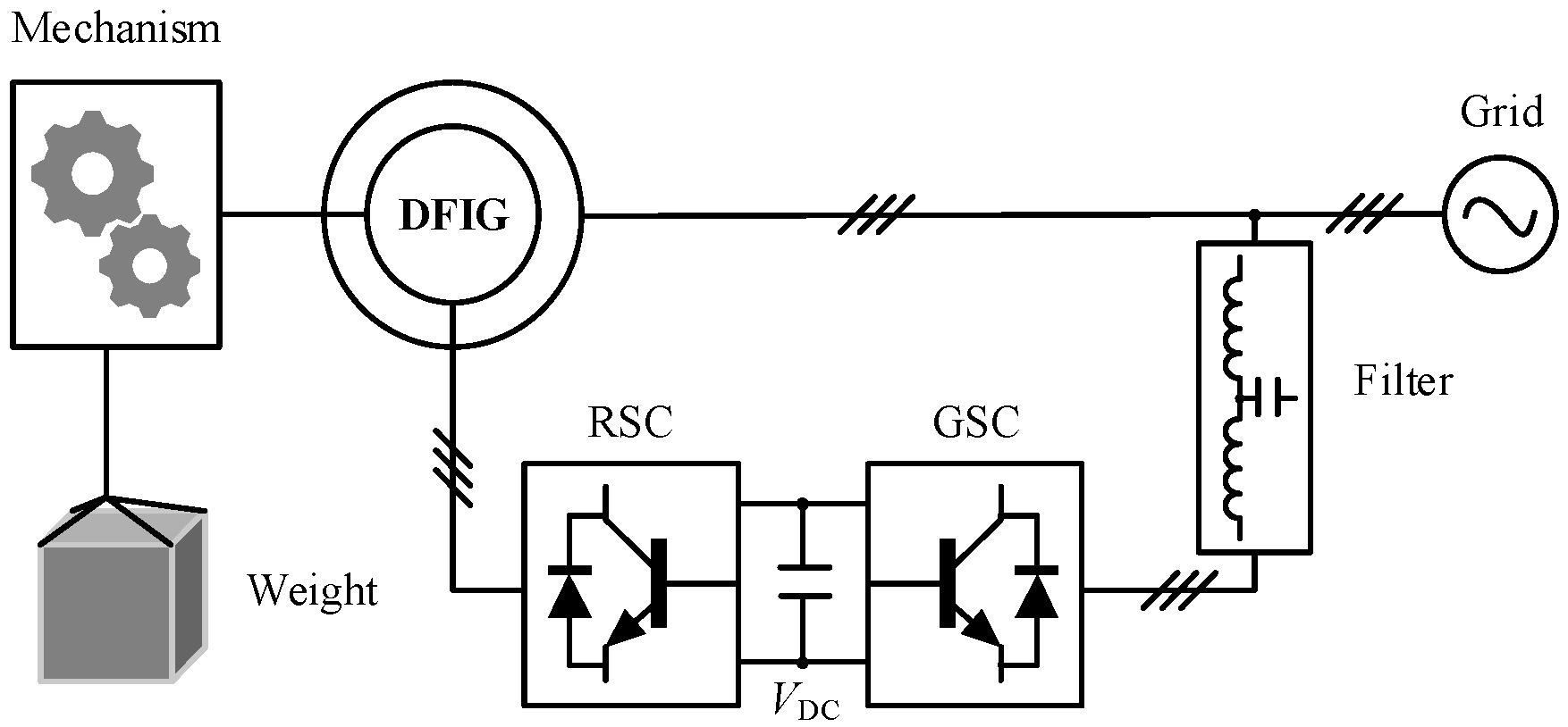
Figure 3 illustrates the overall architecture of the DFIG-GESS. The system primarily consists of the weight block, mechanical transmission components, a DFIG, RSC, GSC, and an LCL filter. In this configuration, the weight block is mechanically coupled to the DFIG rotor through the transmission system. The gravitational potential energy of the weight drives this system, generating a mechanical torque
TL that acts on the rotor. By regulating the rotor speed
ωr, the translational velocity
v of the weight can be precisely controlled during its descent.
2.1. Mechanical Transmission Electronic Control Collaborative System
The mechanical–electrical coordinated transmission system is composed of the mechanical assembly and the DFIG. As illustrated in
Figure 4, the mechanical assembly consists of a pulley block, a wheel-and-axle mechanism, and a gearbox.
The pulley block functions as a multi-stage force transmission system. Its combination of fixed and movable pulleys can be flexibly designed according to the application requirements of the GESS, enabling both directional deflection and magnitude scaling of the force vector.
The wheel-and-axle mechanism works as the translational–rotational conversion hub. Through rope winding, it converts the linear displacement of the weight into rotational motion of the shaft, simultaneously transforming the tensile force into torque and mapping translational velocity into angular velocity. The corresponding physical relationship is expressed as
where
r is the drum radius,
F is the force transmitted by the pulley block, and
v is the rope’s linear velocity.
The gearbox acts as the speed-matching unit, adapting the system power flow through either speed reduction with torque amplification or speed increase with torque reduction. Under ideal conditions, the mechanical torque
TL delivered to the DFIG rotor through the mechanism can be expressed as
where
k is the pulley block ratio,
N is the gear box transmission ratio,
m is the mass of the weight, and
g is the gravitational acceleration.
When the rotor windings rotate relative to the air-gap magnetic field, the interaction between the rotating field and rotor current produces the electromagnetic torque
Te. Thus, the dynamic coupling model between the rotor electromagnetic field and the mechanical load can be established:
where
J is the rotor inertia of the DFIG, and
ωr is the rotor angular velocity.
The DFIG regulates its rotor speed through the rotor-side converter, which adjusts the rotor excitation current to control the speed of the air-gap magnetic field. Consequently, the rotor speed
ωr—which is equivalent to the output shaft speed of the gearbox—is controlled. Since the angular velocity of the wheel-and-axle mechanism is strictly synchronized with the gearbox input shaft, and the translational velocity satisfies Equation (1), regulating the DFIG rotor speed directly controls the translational velocity of the weight:
where
v0 denotes the translational velocity of the weight.
In non-ideal conditions, additional dynamics such as weight inertia and damping
D must be considered:
where
v is the relative translational velocity. The friction force
Ffriction can be modeled as
where
FC is the Coulomb friction force,
Fbrk is the breakaway friction force,
vbrk is the breakaway velocity, and
vSt is the Stribeck threshold velocity.
Correspondingly, the friction torque
Tfriction is given by
where
TC is the Coulomb friction torque,
Tbrk is the breakaway torque,
ωbrk is the breakaway angular velocity,
ωSt is the Stribeck angular velocity threshold,
ωCoul is the Coulomb angular velocity threshold, and
ω is the relative angular velocity.
Finally, the torque TL obtained from the mechanical assembly is regarded as the mechanical input torque Tm to the DFIG.
2.2. System Power Flow Direction and Expression
This section analyzes the energy flow mechanisms of the DFIG-GESS under different operating conditions, thereby laying the foundation for the subsequent development of system control strategies.
The mechanical power generated by the weight and delivered to the mechanical assembly can be expressed as
Under steady-state conditions, the magnetic fields of the DFIG stator and rotor are constant; thus, the electromagnetic power associated with magnetic field energy variation,
Pfield, is zero. Neglecting the losses of the AC-DC-AC converters, the total losses
Ploss of the DFIG-GESS consist of the mechanical losses in the transmission structure (
Pmec), the stator copper loss (
PCu,s), and the rotor copper loss (
PCu,r):
Accordingly, the active power delivered by the DFIG-GESS to the grid can be written as
Through the coordinated mechanical–electrical transmission system, the DFIG-GESS converts the gravitational potential energy of the weight into electrical energy, which is then fed into the grid. The direction of active power flow depends on the translational velocity of the weight, which is determined by the rotor speed. When operating in generating mode, the electromagnetic active power of the DFIG is expressed as
where
ω1 is the synchronous speed,
ωslip =
ω1 −
ωr is the slip speed,
Pes is the stator-side electromagnetic power,
Per is the rotor-side electromagnetic power, and
Pe is the total electromagnetic power.
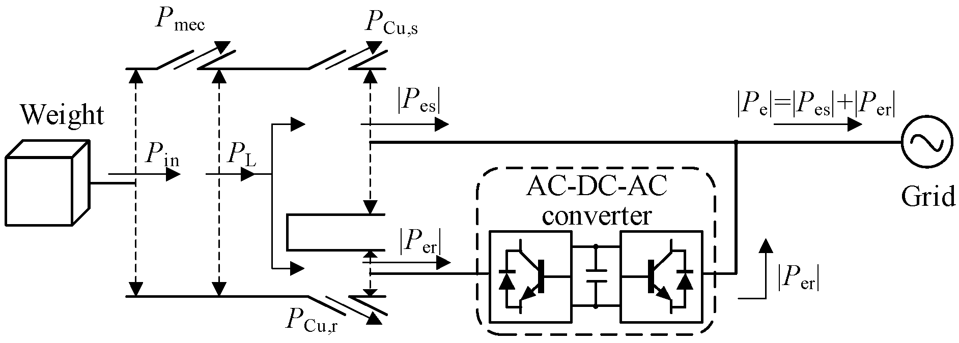
Equation (12) indicates that in the hypersynchronous mode (
ωr >
ω1), the rotor-side power satisfies
Per > 0; the rotor delivers active power, and the system power flow is illustrated in
Figure 5, where
PL denotes the mechanical power transmitted through the mechanism into the DFIG. In contrast, in the sub-synchronous mode (
ωr <
ω1), the rotor-side power satisfies
Per < 0; the rotor absorbs active power, and its electromagnetic power dynamically adjusts with the rotor speed to maintain constant stator electromagnetic power. The corresponding system power flow in this case is shown in
Figure 6.
3. Control Strategies
The control architecture of the AC-DC-AC converter in the DFIG-GESS is shown in
Figure 7. Let
UgABC and
IgABC denote the three-phase voltage at the grid side and the three-phase AC-side current of the GSC, respectively. Similarly, let
UsABC and
IsABC denote the three-phase stator output voltage and current of the DFIG.
The GSC is connected to the point of common coupling (PCC) through an LCL filter. Via the GSC control system and space-vector pulse-width modulation (SVPWM), the three-phase grid supply is actively rectified to a DC voltage, providing a stable DC-link for the RSC. The RSC controls the DFIG using a speed-adaptive droop strategy combined with stator voltage vector-oriented control. This provides the system with active grid-support capability and enables wide-range controllable rotor-speed operation. When the voltages on both sides of the circuit breaker are synchronized—that is, their magnitudes, frequencies, and phases are matched—the breaker closes, allowing the stator-side output power to be delivered to the PCC.
3.1. Speed-Adaptive Droop Control Strategy
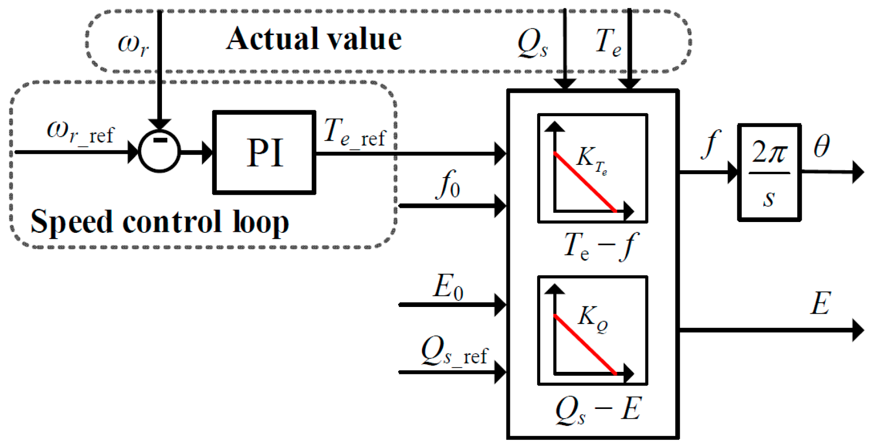
According to the rotor motion Equation (3), the rotor speed
ωr dynamics are governed by the difference between the mechanical and the electromagnetic torque. Since the mechanical torque is determined by the weight and transmission mechanism, controlling the rotor speed requires direct regulation of the electromagnetic torque. To achieve this, a closed-loop speed control scheme is designed, as shown in
Figure 8.
As shown in
Figure 8, the reference speed
ωr_ref is compared with the measured rotor speed
ωr. The resulting error
ωr_error is processed by a proportional–integral (PI) controller to generate the reference electromagnetic torque
Te_ref.
Based on the power flow analysis in
Figure 6, the active power injected into the grid corresponds to the stator electromagnetic power, which is regulated by the RSC. Furthermore, from Equation (12) and neglecting the influence of stator voltage frequency variations, the stator electromagnetic power depends only on the electromagnetic torque and is directly proportional to it. Inspired by the active power–frequency (
P–
Te) droop characteristic of synchronous generators, a droop relationship between electromagnetic torque and frequency is established, as illustrated in
Figure 9.
where
f0 is the rated grid frequency,
Te_ref is the reference electromagnetic torque (from the speed control loop),
Te is the actual electromagnetic torque,
KTe is the electromagnetic torque droop coefficient, and
f is the frequency reference obtained from droop control.
In parallel, the conventional reactive power–voltage (
Q-
V) droop characteristic is adopted to generate the reference stator voltage amplitude
E, as shown in
Figure 10.
where
E0 is the rated grid voltage amplitude,
Qref is the reference stator reactive power,
Q is the actual stator reactive power,
KQ is the reactive power droop coefficient, and
E is the reference stator voltage amplitude.
The frequency and voltage amplitude references obtained from the above droop laws are synthesized into a three-phase voltage reference signal EABC for the stator side. This enables the DFIG-GESS to exhibit the characteristics of a voltage source, similar to conventional droop-based grid-forming control. Consequently, when a fault at the PCC causes a sudden voltage disturbance, the stator reference signal EABC remains stable, providing inherent grid-support capability and allowing standalone operation for local loads. In contrast, grid-following control relies on a PLL to track the grid voltage and thus behaves as a current source. In such cases, voltage disturbances at the PCC propagate directly to the system output, resulting in limited grid-support capability.
Furthermore, from Equation (13), the intercept
b of the torque-frequency droop curve can be expressed as
Unlike conventional droop control, where Pref is predefined, the proposed speed-adaptive droop control dynamically sets Te_ref based on the output of the speed loop. Consequently, the droop curve shifts vertically in real time according to the rotor speed, achieving adaptive adjustment.
The overall structure of the proposed speed-adaptive droop control strategy is illustrated in
Figure 11.
3.2. RSC Control Strategy
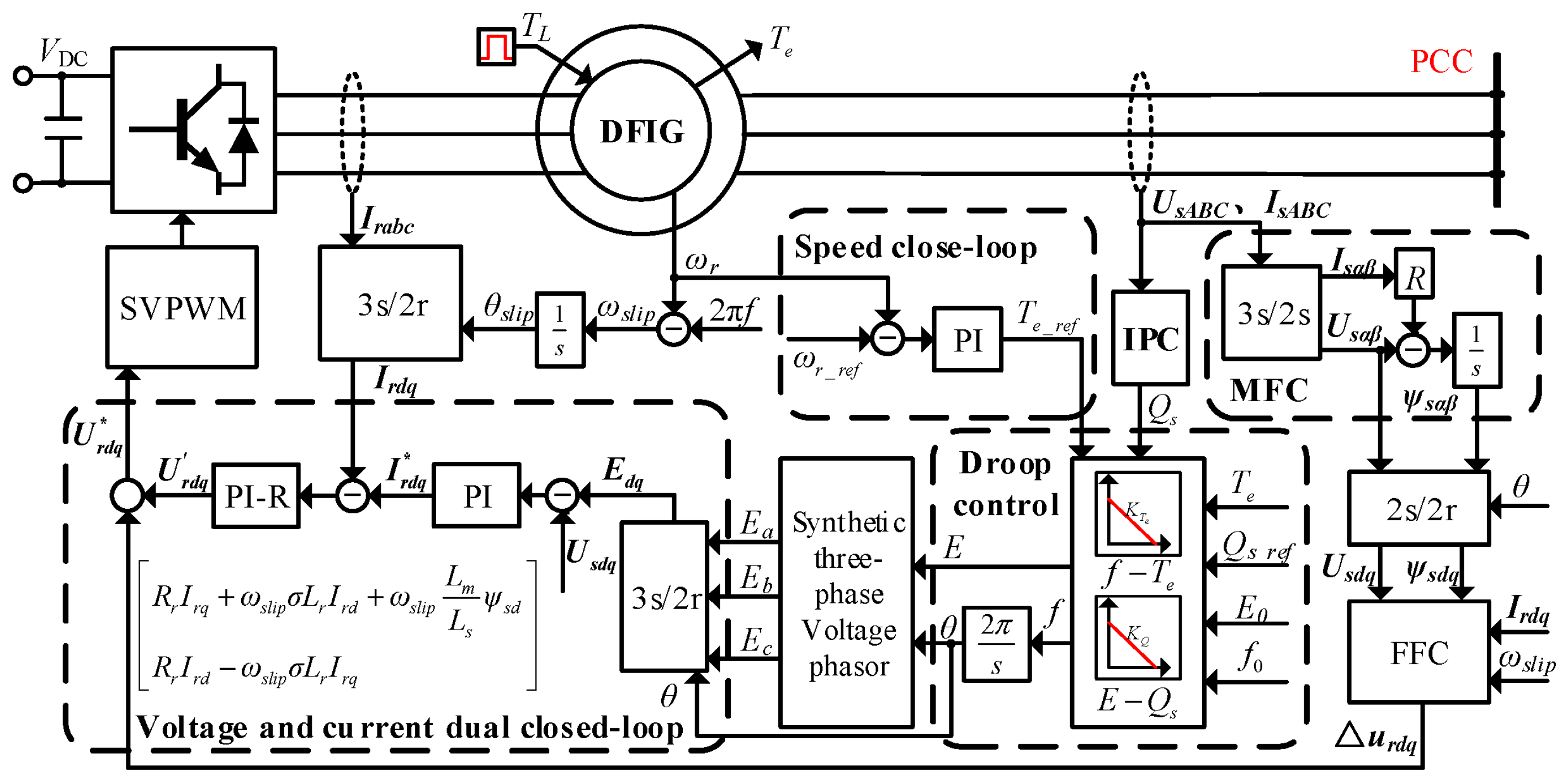
The control scheme of the RSC in the DFIG is illustrated in
Figure 12. The stator is directly connected to the grid or a local load, while the rotor side is connected to the converter. The converter is supplied by a regulated DC bus, which is maintained by the GSC. The gravitational potential energy of the suspended mass is converted into a mechanical torque
TL through the mechanical system and applied to the DFIG. The rotor speed
ωr and electromagnetic torque
Te of the machine are measured for feedback control.
The RSC control system integrates multiple modules, including the speed closed-loop control, magnetic flux calculation (MFC), coordinate transformation, feed-forward calculation (FFC), instantaneous power calculation (IPC), droop control, three-phase voltage phasor synthesis, and voltage-current dual-loop control. The speed loop combined with the droop control constitutes the core proposed speed-adaptive droop control strategy. The control procedure is detailed below.
The measured rotor speed ωr is compared with its reference speed ωr_ref. The resulting speed error is processed by the speed controller to generate the reference electromagnetic torque Te_ref, which is then fed to the droop control module.
The droop control module generates the frequency reference f. Combined with the voltage amplitude reference E from the Q-V droop, it synthesizes the three-phase stator reference voltage EABC.
This reference voltage signal undergoes Clark and Park transformations. The transformed signal is then used as the input to the voltage–current dual closed loops, which compute the reference rotor-side voltage in the dq reference frame.
Finally, the SVPWM algorithm generates the switching signals for the RSC power devices, thereby regulating the DFIG rotor speed and providing grid-supporting capability.
4. Simulation Verification and Case Analysis
A simulation model of DFIG-GESS was established in MATLAB/Simulink. The system performance was tested under both islanded operation and grid-connected operating conditions. For islanded operation, the objectives were to verify the droop characteristics and the speed-tracking performance of the proposed control strategy. In grid-connected mode, the evaluation focused on the active power injection through both the stator and rotor channels, as well as the system’s capability to regulate the grid frequency through adjustments in mechanical torque and rotor speed.
In the proposed control strategy, the torque-frequency droop coefficient KTe is selected to ensure precise speed tracking, provide primary frequency support without exceeding converter or current limits, and maintain small-signal damping of the grid-forming loop. The selection process involves mapping performance to bounds (defining maximum frequency deviation and torque error), respecting converter constraints (adjusting KTe to avoid current limits), and verifying small-signal damping. A smaller KTe is used for islanded operation to tighten frequency regulation, while a larger KTe is chosen for grid-connected operation to avoid unnecessary frequency bias.
PI parameters are tuned sequentially, starting with the inner loops (current and voltage control) and then the outer speed loop. The current loop is first adjusted by increasing the proportional gain for a fast, stable response. Once stabilized, the integral gain is adjusted to minimize steady-state error. After stabilizing the current loop, the voltage loop is tuned for stable output, and then the speed loop is adjusted to ensure precise speed tracking. This method ensures stable and precise control across the system.
Based on the above parameter-tuning methodology, the final settings of the simulation parameters are shown in
Table 2.
4.1. Islanded Operation
Under islanded conditions, the speed reference was varied to verify the consistency between the frequency of the stator voltage f and the electromagnetic torque Te, as defined by the constructed Te-f droop curve. The mechanical torque from the suspended mass was fixed at −0.8 p.u., and the stator supplied a constant local load.
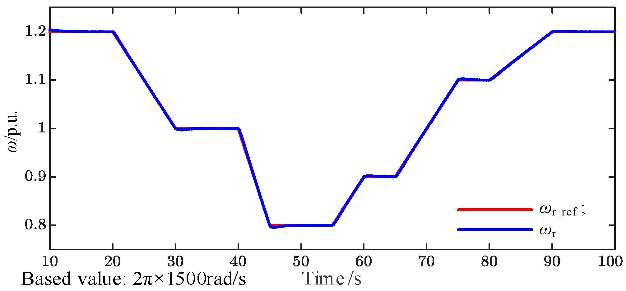
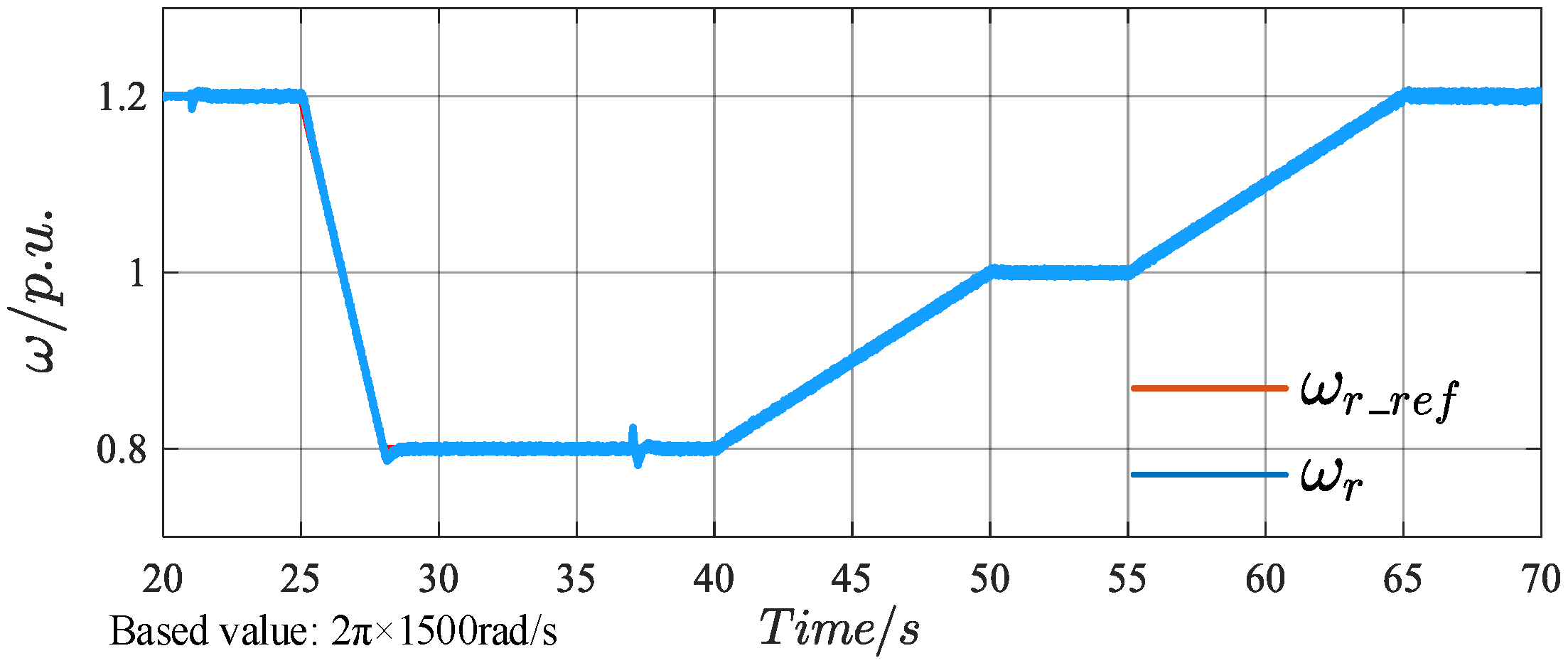
Figure 13 shows the time-domain waveforms of the reference and actual rotor speeds. The rotor speed
ωr (blue curve) accurately tracks the reference
ωr_ref (red curve) with a negligible steady-state error across a wide speed range, demonstrating the effectiveness of the speed closed-loop control. At 20 s, the reference speed changes from a constant value to a ramp signal, and the settling time corresponding to a rotor-speed deviation of less than 0.1% is 0.5 s. At 30 s, the reference speed changes from the ramp signal to a constant value, with an overshoot of 0.2% and a settling time of 0.4 s.
Figure 14 presents the measured electromagnetic torque and rotor-speed waveforms. The filtered electromagnetic torque
Te_LPF (red) closely tracks the applied mechanical torque
TL when the rotor speed
ωr is stable, which validates the torque-speed dynamics predicted by Equation (3).
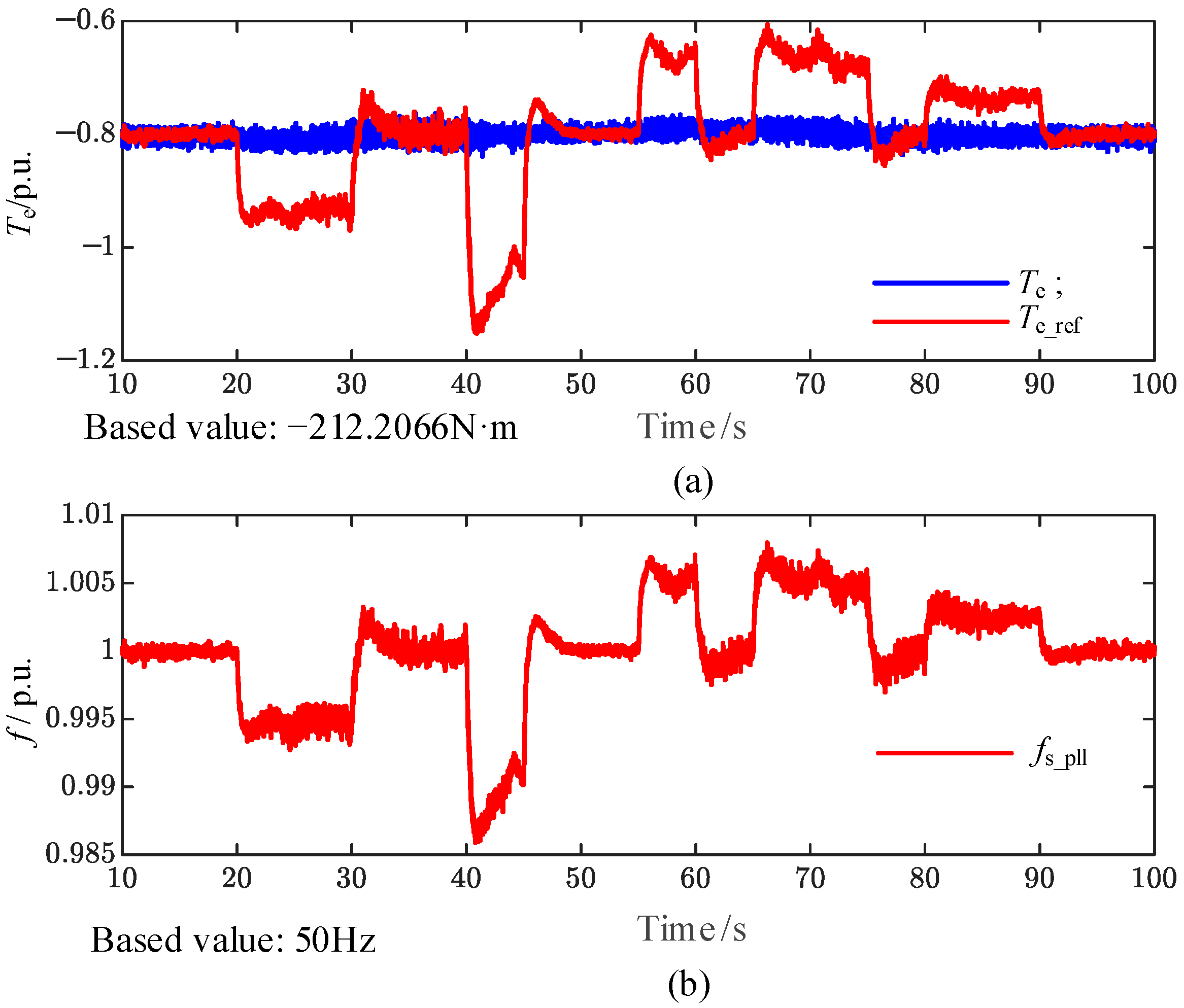
Furthermore,
Figure 15 compares the electromagnetic torque reference
Te_ref with the actual torque
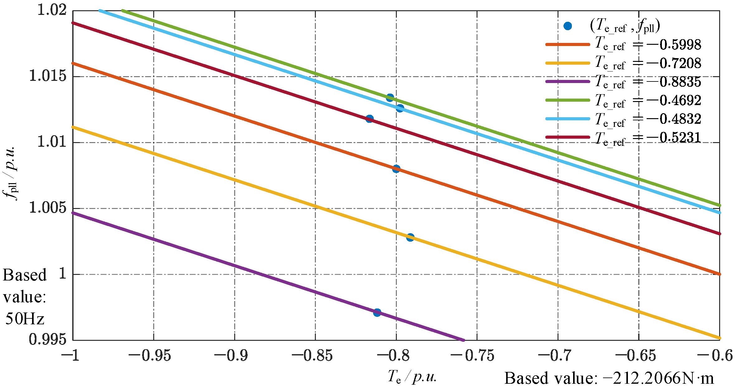
Te, together with the stator frequency measured by a PLL. Clearly, the torque tracking error is directly correlated with the frequency deviation, which is consistent with the implemented droop control law. A linear fit of the measured data produces the
Teo-
f droop curve shown in
Figure 16, confirming that the adaptive mechanism shifts the droop characteristic based on the dynamic value of
Te_ref.
4.2. Grid-Connected Operation
In the grid-connected scenario, a step change in mechanical torque was applied at t = 37 s by engaging an additional mass, causing TL to change from −0.8 p.u. to −1.0 p.u.
The speed waveform is shown in
Figure 17. At 37.028 s, the speed reaches its maximum value of 0.814 p.u., and at 37.154 s, it drops to its minimum value of 0.7598 p.u., with an overshoot of 4.02%. It illustrates that the rotor speed exhibits only minor transients during the torque step and subsequently maintains accurate tracking of its reference
t, demonstrating the robustness of the proposed control strategy.
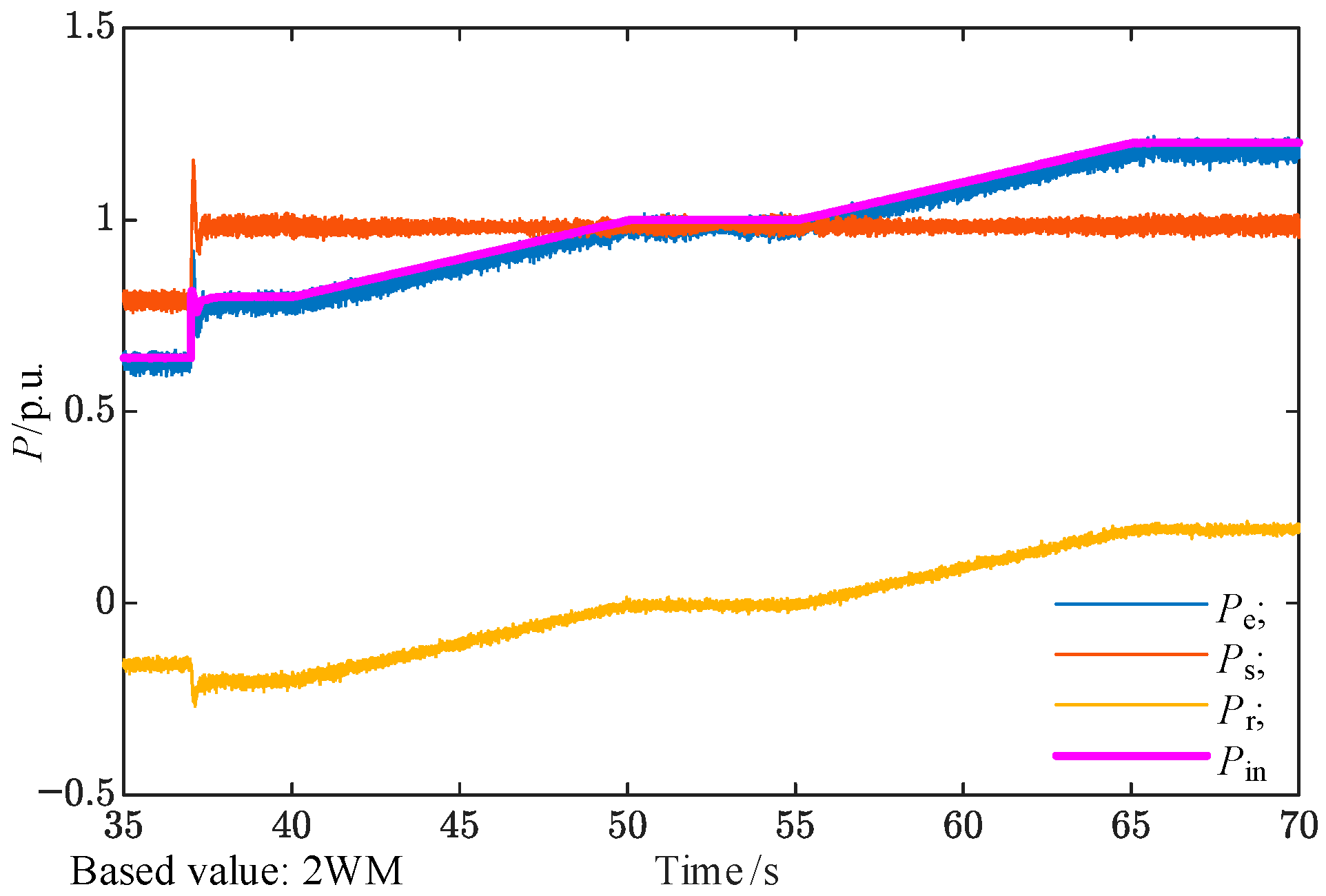
The system’s active power responses are shown in
Figure 18. The total electromagnetic power
Pe (blue) closely matches the mechanical input power
Pin (purple), with small discrepancies attributable to damping, friction, and machine inertia. The stator power
Ps remains independent of rotor speed, while the rotor power
Pr varies linearly with
ωr. Specifically, when
ωr exceeds the synchronous speed, the rotor absorbs active power, whereas below the synchronous speed, it delivers active power.
Moreover, as shown in
Figure 19, the system provides effective grid-frequency support. The PCC frequency, measured by a PLL, increases from 49.68 Hz to 49.95 Hz following the adjustments in mechanical torque and rotor speed. By adding or removing the heavy load, the frequency at the PCC stabilizes at 49.75 Hz after 37 s. At 37.077 s, the PCC frequency reaches its maximum value of 49.8 Hz, and at 37.227 s, it drops to its minimum value of 49.72 Hz, with an overshoot of 1%. By adjusting the rotor speed, the frequency at the PCC stabilizes at 49.85 Hz after 50 s, and at 49.95 Hz after 65 s.
The proposed control strategy still ensures precise control of the rotor speed under grid fault conditions. At the 21 s mark, a grid fault is applied (phase A grid voltage drops from 1 p.u. to 0.8 p.u.), and at the 37 s mark, an additional mass is abruptly added, causing a step change from 0.8 p.u. to 1 p.u. The rotor-speed waveform is shown in
Figure 20, where
ωr_ref (the red line) represents the rotor-speed reference value, and
ωr (the blue line) represents the actual rotor speed. As can be seen, after the grid fault, the rotor speed spikes, but the system continues to follow the reference speed command. Additionally, under grid fault conditions, when the mass is suddenly added, the actual rotor speed stabilizes immediately after a brief fluctuation.
4.3. Analysis of DFIG-GESS Operation Under Three-Phase Rapid Voltage Sag
The following simulation analyzes the operation of the DFIG-GESS system under a grid voltage sag from 1 p.u. to 0.3 p.u. The rotor-speed waveform is shown in
Figure 21, where
ωr_ref (the red line) represents the rotor-speed reference value, and
ωr (the blue line) represents the actual rotor speed. The time instances
t1,
t2,
t3, and
t4 correspond to the settings under different operating conditions.
At
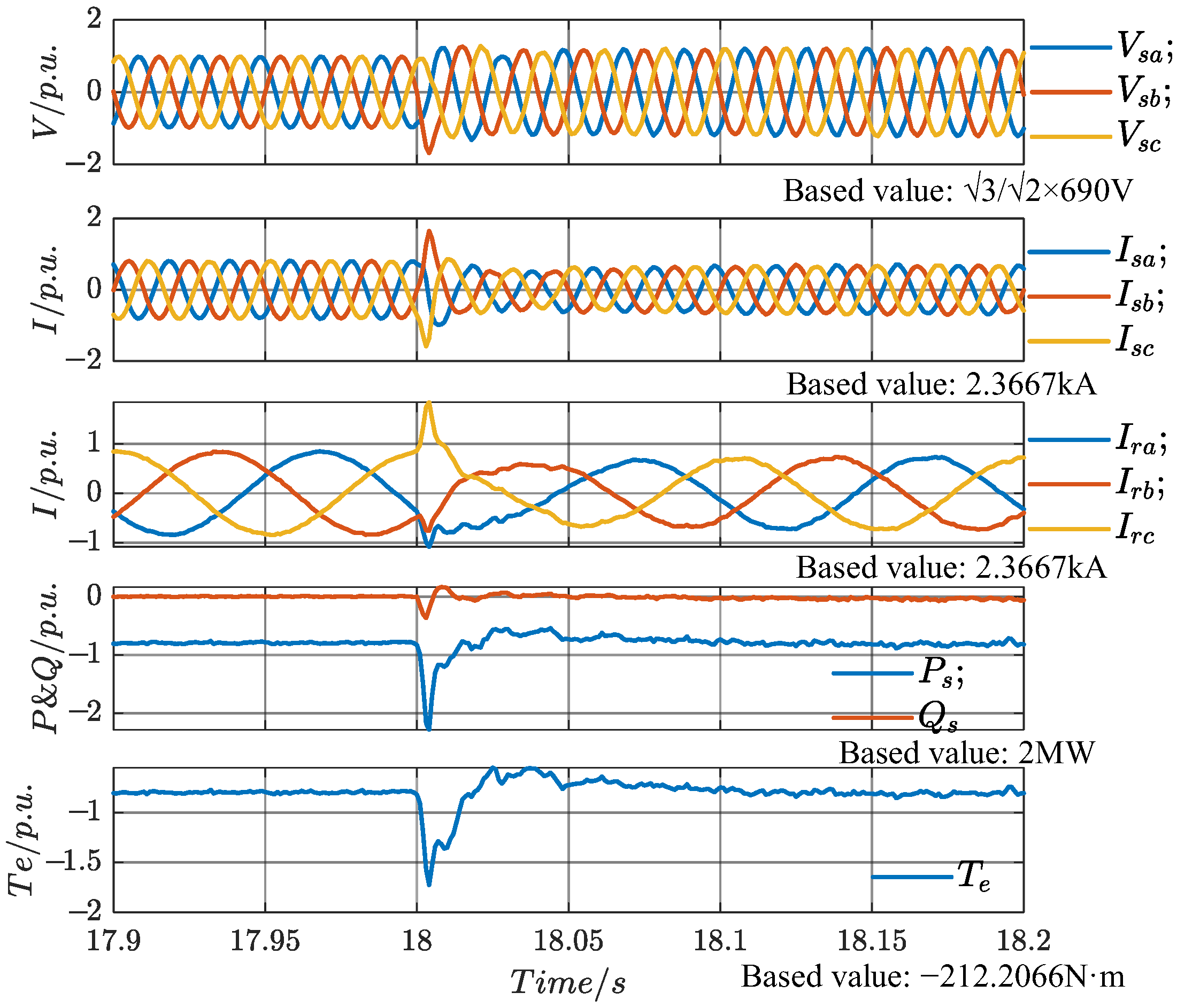
t1 (18 s), the load at the PCC is disconnected, causing the active power generated by the DFIG-GESS to be entirely transmitted to the grid through the line impedance. The stator voltage and current, rotor current, stator power, and electromagnetic torque are shown in
Figure 22. The sudden load disconnection at
t1 (18 s) causes fluctuations in the stator voltage and current, which stabilize after half a cycle. Additionally, due to the presence of line impedance, the increase in active power fed into the grid raises the PCC voltage magnitude from the original 1 p.u. to 1.253 p.u., demonstrating that, under weak grid conditions, the system can support the grid voltage by increasing the active power output, thereby providing voltage support at the PCC.
The electromagnetic torque drops to its minimum value of −0.522 p.u. at 18.026 s, with an overshoot of 27% and a settling time of 0.05 s. The speed waveform is shown in
Figure 23 below. At 18.02 s, the speed drops to its minimum value of 1.165 p.u., and at 18.138 s, it reaches its maximum value of 1.209 p.u., with an overshoot of 3.5%.
At
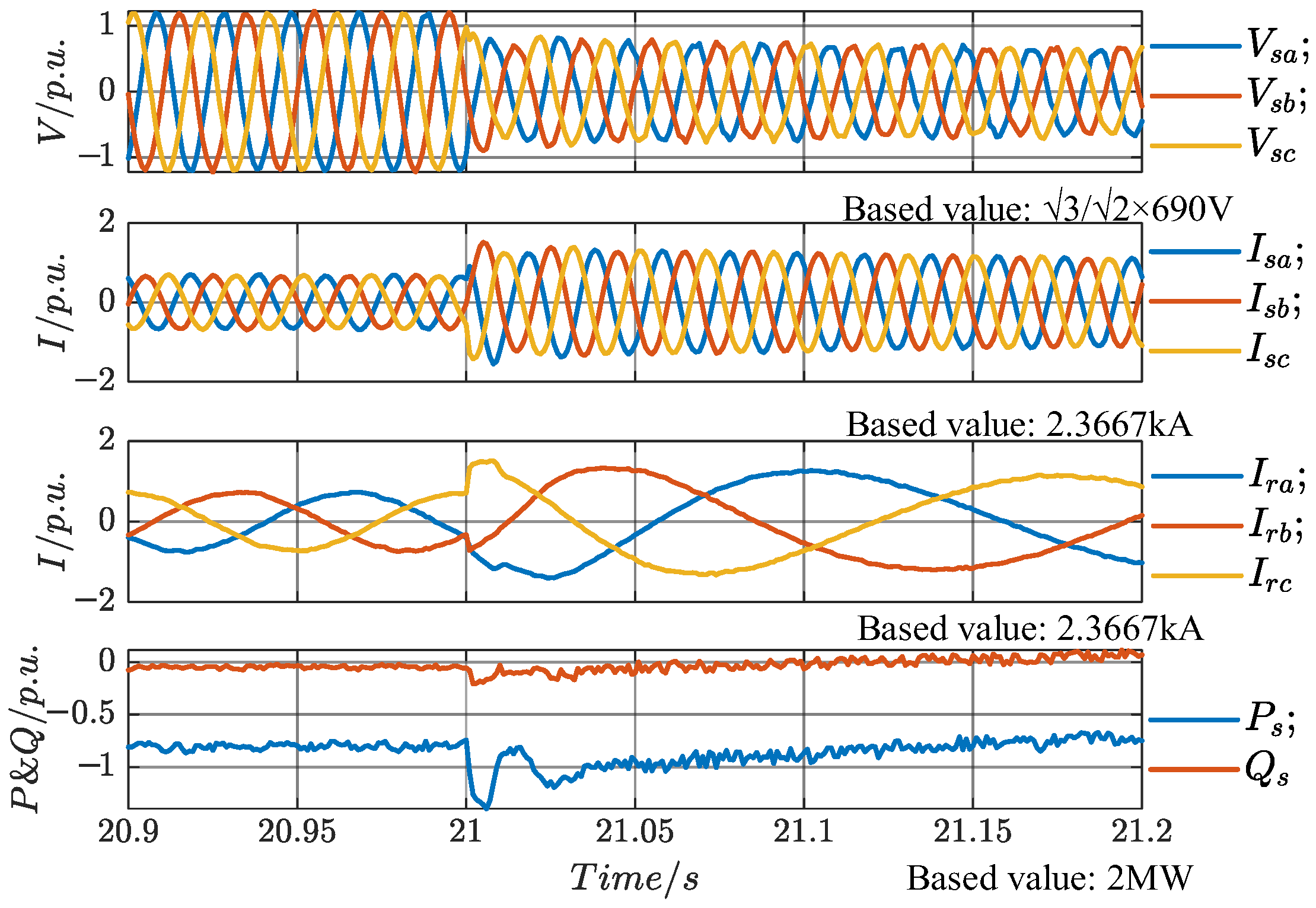
t2 (21 s), a sudden three-phase fault occurs in the grid, causing the grid voltage to drop from the original 1 p.u. to 0.3 p.u., with no recovery. The stator voltage and current, rotor current, and stator power are shown in
Figure 24. Due to the grid fault, the stator voltage drops from 1.253 p.u. to 0.7624 p.u. Compared to the 70% drop in the grid voltage, the PCC voltage only drops by 49%. After the fault, the grid voltage is 0.3 p.u., and the PCC voltage is 0.7624 p.u., demonstrating that the system can still provide voltage support under grid fault conditions.
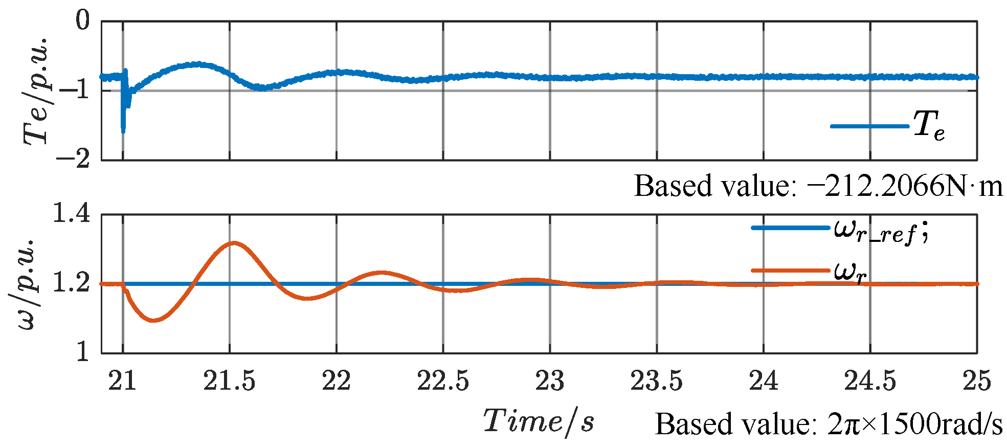
The electromagnetic torque and speed waveforms are shown in
Figure 25. The electromagnetic torque drops to its minimum value of −1.612 p.u. at 21.002 s, with an overshoot of 81.2%, and enters the ±5% error band at 22.388 s, with a settling time of 1.388 s. At 21.14 s, the speed drops to its minimum value of 1.094 p.u., and at 21.52 s, the speed reaches its maximum value of 1.318 p.u., with an overshoot of 11%. The speed enters the ±5% error band at 21.653 s, with a settling time of 0.653 s.
At
t3 (28 s), the speed reference changes from a ramp signal to a constant.
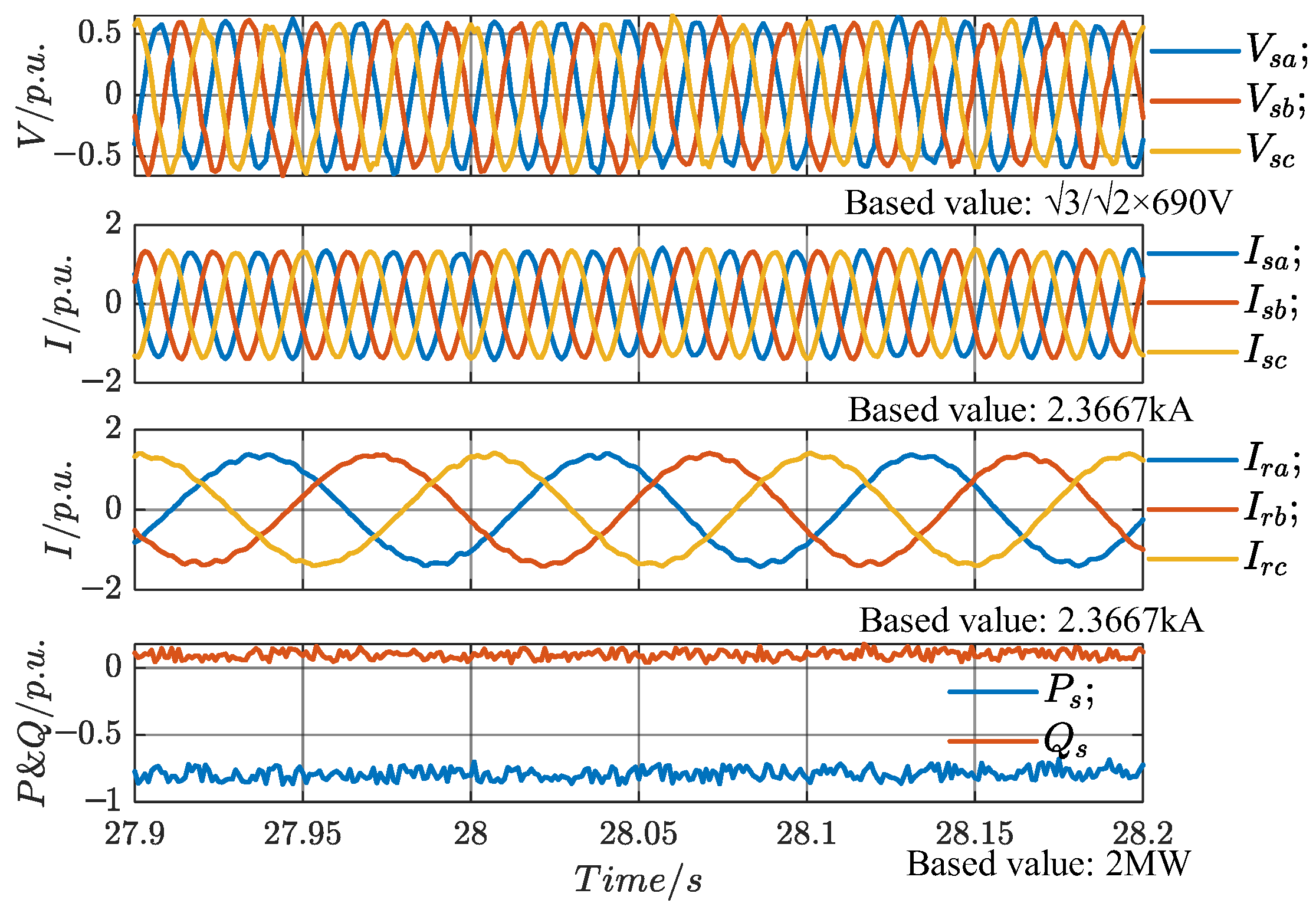
Figure 26 shows the stator voltage and current, rotor current, and stator power waveforms, all of which are in steady-state operation and unaffected by the change in the speed reference. However, during the interval from
t2 to
t3, the ramp change in speed causes variations in the active power fed to the grid by the rotor, resulting in a reduction in the total active power delivered to the grid. As a result, the PCC voltage magnitude gradually decreases in this interval, as shown in the figure. After
t3 (28 s), the measured PCC voltage magnitude during the subsequent cycle is 0.6628 p.u., which represents a 9.96% decrease compared to the 0.7624 p.u. at
t2. This demonstrates that the system can regulate the rotor speed to modify the total active power delivered to the grid, thereby adjusting the PCC voltage magnitude.
The speed waveform is shown in
Figure 27. At 28.22 s, the speed drops to its minimum value of 0.7829 p.u., and at 28.624 s, it reaches its maximum value of 0.8148 p.u., with an overshoot of 1.71%.
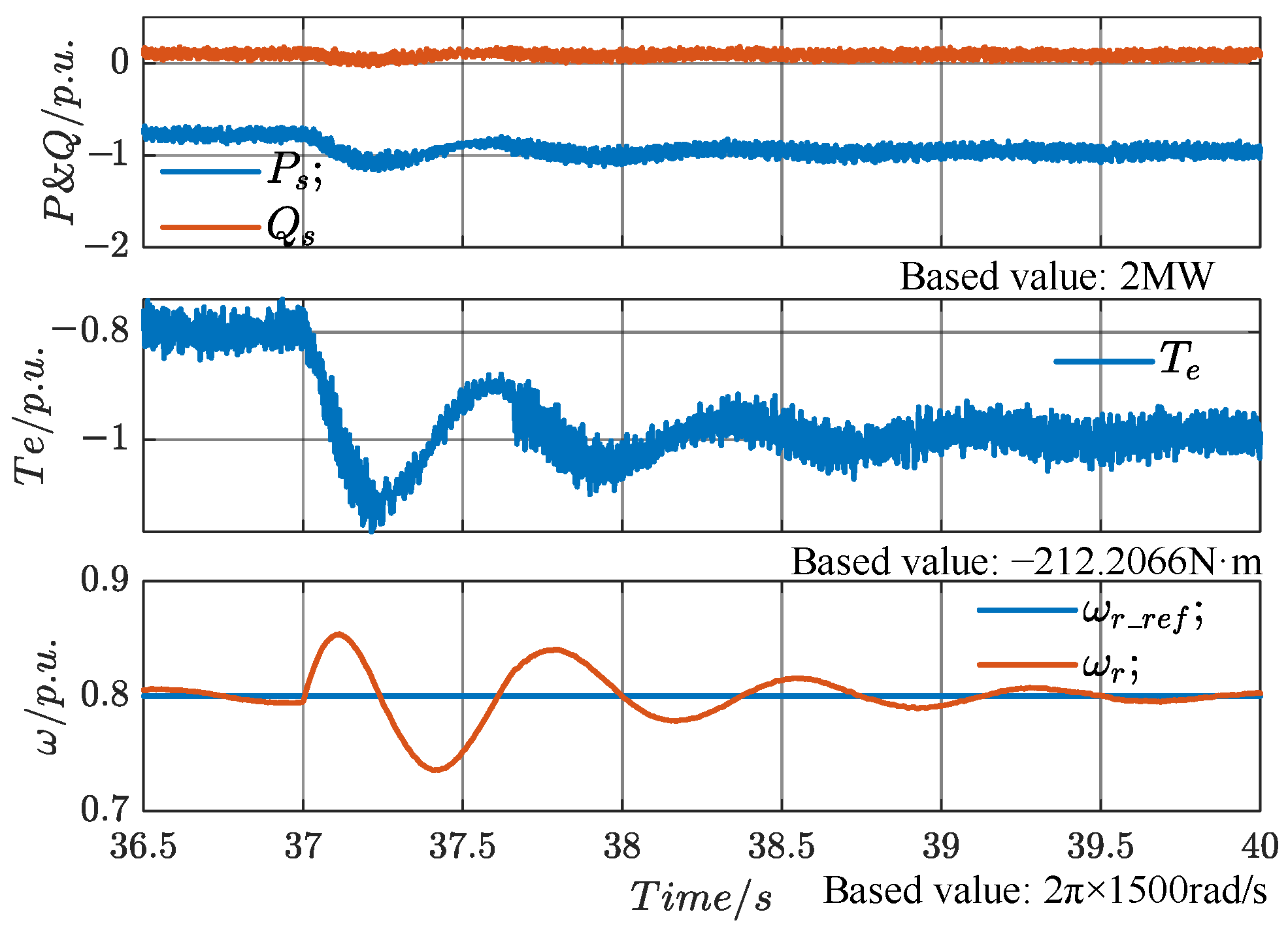
At t4 (37 s), a sudden addition of a heavy load causes the load torque to drop abruptly from 0.8 p.u. to 0.2 p.u. After stabilization, the PCC voltage magnitude is measured at 0.704 p.u., which represents a 4.12% increase compared to the 0.6628 p.u. at t3. This demonstrates that the system can regulate the PCC voltage magnitude by adding or removing heavy loads, thus adjusting the total active power delivered to the grid.
The stator power, electromagnetic torque, and speed waveforms are shown in
Figure 28. The electromagnetic torque reaches its minimum value of −1.18 p.u. at 37.243 s and further drops to −0.8771 p.u. at 37.582 s, with an overshoot of 18%. It enters the ±5% error band at 38.402 s, with a settling time of 1.402 s. The speed reaches its maximum value of 0.854 p.u. at 37.11 s, and drops to its minimum value of 0.7356 p.u. at 37.408 s, with an overshoot of 6.44%. The speed enters the ±5% error band at 37.498 s, with a settling time of 0.498 s.
Based on
Figure 21 and the above analysis, it can be concluded that under a three-phase symmetrical fault in the grid, the DFIG-GESS is still capable of precise rotor-speed control and voltage support.
5. Conclusions
This paper proposed a GESS architecture based on a doubly fed induction machine and developed a speed-adaptive droop control strategy. The proposed architecture facilitates efficient energy conversion between gravitational potential energy and electrical energy, while enabling wide-range, high-precision speed control of the suspended mass. A key advantage of the proposed control strategy is its enhancement of the system’s grid-support capability, achieved under low converter cost by combining speed adaptability with the benefits of conventional droop control. Simulation results demonstrate the effectiveness of the proposed control strategy in both islanded and grid-connected operating modes.
While the simulation results indicate that the proposed strategy effectively improves grid support, it is acknowledged that further improvements are needed in robustness testing under real-world disturbances, such as faults and voltage sags. Future work will focus on addressing these practical challenges by incorporating fault ride-through capabilities and conducting experimental validation, either through hardware-in-the-loop (HIL) testing or real-world implementation. Additionally, more detailed quantitative performance metrics, such as overshoot, settling time, and RMS error, will be provided to offer a more comprehensive comparison with traditional droop control.
Overall, this research contributes to the development of advanced control strategies for DFIG-based GESS, offering a promising solution for enhancing grid stability and supporting the integration of renewable energy sources into modern power grids.
