Abstract
Motors are among the most energy-consuming devices worldwide. With growing interest in eco-friendly solutions, minimum efficiency regulations for industrial motors are being enforced. In response to continuously rising minimum efficiency requirements, research on improving the efficiency of motors is actively underway. In the case of induction motors, which are the most widely used industrial electric motors, rotor ohmic loss occurs due to their operating characteristics. In contrast, line-start synchronous reluctance motors (LS-SynRMs) have a significant advantage in efficiency because once they reach synchronous speed, no eddy currents are generated by the fundamental current waveform. This leads to a sharp decrease in rotor ohmic losses, greatly enhancing efficiency. In this paper, a rotor design is carried out to improve the efficiency of LS-SynRMs. To support the rotor design, the torque characteristics of LS-SynRMs were analyzed under both asynchronous and synchronous state operations, and improvement directions for enhancing efficiency were identified. For rotor type selection, two bar-type rotors with linear flux barriers and two boomerang-type rotors with curved flux barriers were designed. The electromagnetic characteristics of these designs were compared using finite element analysis. Among them, the boomerang-type rotor that exhibited the best electromagnetic performance was selected as the final rotor type. Its final geometry was derived through detailed design, considering the mechanical safety of the rotor. Finally, experimental validation was conducted to verify the effectiveness of the proposed rotor design.
1. Introduction
As interest in environmental sustainability continues to grow, the implementation of minimum energy performance standards (MEPS) for electric motors is underway, which represent a prominent energy-consuming device, constituting approximately 53% of total global electricity consumption. The efficiency of motors is classified into five levels, ranging from the lowest efficiency level, IE1, to the highest, IE5 [1]. Figure 1 shows the IE rating of four-pole motors. Currently, the production of motors with efficiency levels of IE3 and above is mandated, with active research aimed at raising the minimum efficiency rating to IE4.
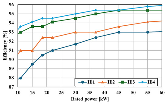
Figure 1.
IE1 to IE4 efficiency classes for 4-pole 10 kW to 60 kW motors.
Induction motors (IMs), the most commonly used type in industrial applications, offer advantages such as easy production and low cost [2,3]. However, due to their operational characteristics, they incur rotor ohmic losses, accounting for approximately 25% of the total losses in IMs [4,5,6,7,8]. Line-start synchronous reluctance motors (LS-SynRMs) offer advantages such as ease of manufacturing, lower production costs, and the ability to utilize the benefits of induction motors without requiring inverter-based control. Additionally, once they reach a steady state, LS-SynRMs do not generate rotor ohmic losses from the fundamental components of the load current, making them advantageous for reducing losses [9]. However, unlike induction motors, where appropriate slip is determined based on the load, LS-SynRMs can only operate as motors when they reach a synchronous speed [10,11].
Therefore, active research is underway to address the limitations of LS-SynRMs and comply with increasingly stringent minimum efficiency regulations. H. C. Liu studied the optimal design of the rotor, additional losses that may occur during the rotor manufacturing process, and the resulting changes in synchronous performance [12,13]. H. Kim researched optimal rotor design techniques for LS-SynRMs, considering both efficiency and power factor, as well as ensuring start-up performance by accounting for the maximum allowable moment of inertia for the rotor [9,14]. Additionally, M. Farhadian explored methods to minimize the use of rotor conductors [15]. However, these studies mainly focused on small motors with a power rating of under 4 kW. In the United States, small-capacity motors rated at 15 kW or below account for approximately 77% of all installed industrial motors, yet their share of total electricity consumption is less than 18%. Medium-capacity motors, rated from 15 kW to 75 kW, represent the next largest group, comprising 18.7% of installations but accounting for approximately 30% of total power consumption. Therefore, considering both motor demand capacity and electricity consumption, improving the efficiency of medium-capacity motors is more effective than enhancing small-capacity motors [16].
When designing LS-SynRMs, it is important to consider both the characteristics of IMs and SynRMs due to the nature of their operational features. The rotor bars, which significantly influence asynchronous state performance, should be designed with IM principles in mind to ensure start-up performance. Research has been conducted on the optimal combinations of the number of stator slots and rotor bars to generate uniform magnetic torque during IM operation, with specific recommendations depending on the number of poles. These combinations typically assume uniform spacing of the conductor bars [17,18,19,20,21]. However, in the synchronous state, when the motor operates as a SynRM, uniformly spaced conductor bars can obstruct the flow of the d-axis flux, potentially leading to a significant decline in performance. Therefore, to maximize the performance of LS-SynRMs, it is beneficial to prioritize synchronous state performance during the initial design and then adjust the conductor bar design within a range that does not significantly affect the synchronous state performance.
When conducting electromagnetic analysis for motor design, both the steady-state and transient modes can be used. The analysis using steady-state mode employs a current source approach, allowing for the motor’s characteristics to be quickly evaluated. However, industrial motors do not directly input the desired current. Instead, the current characteristics are influenced by the load applied to the motor. Predicting the load current characteristics based on load and rotor shape during motor design is challenging. Current characteristics, such as magnitude, phase angle, and harmonic components, have a significant impact on the motor’s output power and losses. Therefore, analysis using steady-state mode, which uses a current source, cannot accurately assess the motor’s characteristics. Instead, to accurately analyze the motor’s characteristics, it is essential to use transient mode, which allows for voltage source analysis and can accommodate varying current characteristics under changing conditions. Therefore, all finite element analyses (FEA) conducted in this study were performed using transient mode.
This paper aims to design a four-pole 37 kW LS-SynRM rotor that meets IE4 efficiency for industrial applications. The IE4 efficiency for a 37 kW motor is 95.4%. To achieve this aim, we first analyzed the operating principle of the LS-SynRM. Subsequently, we designed and compared the characteristics of two types of rotors: bar-type rotors with straight flux barriers and boomerang-type rotors with curved flux barriers. Among the four rotor designs, the one with the best efficiency was selected for further refinement, considering manufacturability. Additional design considerations were made to ensure the start-up performance necessary to reach synchronous speed, as well as manufacturability and mechanical rigidity. The mechanical safety of the rotor during operation was verified through FEA. Finally, the validity of the LS-SynRM design was analyzed through performance testing.
Through this paper, we extended the scope of research beyond previous works that focused only on small-capacity LS-SynRMs with a power rating of under 15 kW and conducted a high-efficiency design for a medium-capacity 37 kW motor. Using 2D FEA, the advantages of the boomerang-type rotor over the bar-type rotor were demonstrated, and a design methodology that simultaneously considers efficiency improvement and mechanical safety of the boomerang-type rotor is proposed. This approach not only fills a gap in the field of medium-capacity LS-SynRM design but also provides important insights into the future development of high-efficiency LS-SynRMs.
2. Operating Principle
The LS-SynRM operates similarly to an IM in an asynchronous state and operates like a SynRM once it reaches synchronous speed. Therefore, the operating principle of LS-SynRM should be analyzed separately for both the synchronous and asynchronous states.
2.1. Synchronous State Operating
When the rotor of an LS-SynRM reaches a synchronous speed, it operates in the same way as a standard SynRM. Therefore, the torque equation can be expressed as shown in Equation (1) [9,19].
Here, p is the number of pole pairs, Ld and Lq are the inductance of the d-axis and q-axis, respectively, and id and iq are the current of the d-axis and q-axis, respectively. LS-SynRMs operate based on a constant input voltage without directly controlling the input current. Therefore, to analyze its characteristics, Equation (1) should be converted into an expression that utilizes the input voltage and reactance, as shown in Equation (2) [19].
Here, Va is the input voltage, Rs is the stator resistance, Xd and Xq are the reactance of the d-axis and q-axis, respectively, and δv is the voltage angle. In Equation (2), there are two methods to increase the maximum torque. One method is to reduce the stator resistance, and the other is to maximize the gap between the d-axis and q-axis inductances. Due to the operating characteristics of the LS-SynRM, a load current is generated according to Equation (1) when load torque acts on the system. Therefore, when the load torque is the same, the inductance gap between the d-axis and q-axis becomes inversely proportional to the load current. To improve motor efficiency in synchronous state operation, maximizing this inductance difference is important. In Section 3 of this paper, design parameters are selected to determine the appropriate width and length of the rotor flux circuit in order to maximize the difference between the d-axis and q-axis inductances, and these parameters are incorporated into the rotor design.
2.2. Asynchronous State Operating
In the asynchronous state, while the LS-SynRM operates on a principle similar to that of an IM, it differs from the IM by having the inductance gap between the rotor’s d-axis and q-axis. Therefore, the torque in the asynchronous state can be expressed as shown Equation (3) [4,9,22].
Here, Tas is the asynchronous torque, Tavg is the electromagnetic torque generated by the rotor conductor bars, and Trel is the magnitude of the reluctance torque. s is the slip, and ωe is the angular frequency of the synchronous speed, while α is the phase angle of the reluctance torque. The reluctance torque is generated due to the inductance gap. Although the average value of the reluctance torque is zero, it induces torque ripple in the asynchronous state. Figure 2 shows the torque–speed curve of the LS-SynRM. As the motor operates, a load torque is applied to the rotor, resulting in start-up with a large load current that generates a significant instantaneous torque. Over time, as the load current stabilizes, the torques resulting from Tavg and Trel become apparent.
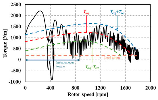
Figure 2.
Torque–speed curve of the LS-SynRM.
To ensure that the LS-SynRM reaches synchronous speed safely, Tavg must exceed the load torque near the synchronous speed. Considering the characteristics of the rotor, which has the inductance gap, Tavg can be expressed by decomposing it into d-axis and q-axis components, as shown in Equation (4) [9,18].
Here, Rdr and Rqr are the rotor’s d-axis and q-axis resistance, respectively, Ldm and Lqm are the d-axis and q-axis magnetizing inductance, respectively, Ldr and Lqr are the rotor’s d-axis and q-axis inductance, respectively, and Lds and Lqs are the stator’s d-axis and q-axis inductance respectively. As the rotor speed approaches a synchronous speed, the slip approaches zero. At this point, the average torque Tavg can be expressed as shown in Equation (5) [9,19].
Through rotor design, it is important to reduce the values of Rdr and Rqr in order to increase the magnitude of Tavg. The rotor resistance is closely related to the size of the rotor bar area. Therefore, to ensure start-up performance, it is crucial to secure sufficient rotor conductor bars during the design process.
3. Basic Design of LS-SynRM Rotors
The bar-type rotor has the advantage of being relatively easy to manufacture due to its simple shape. On the other hand, the boomerang-type rotor has the drawback of being more difficult to manufacture due to the curvature of the flux barriers. However, the boomerang-type rotor reduces magnetic resistance by shortening the magnetic path along the d-axis, which increases the inductance gap between the d-axis and q-axis. This allows for sufficient inductance gaps with a smaller number of flux barrier layers. If the inductance difference remains the same but the number of flux barriers is reduced, the width of the rotor core forming the flux path becomes wider, leading to a lower magnetic flux density in the rotor core. This reduction in flux density results in decreased iron loss, which can increase efficiency. Therefore, we designed both rotors and compared their characteristics to select the superior rotor type.
Figure 3 shows the rotor design algorithm for achieving IE4 efficiency in an LS-SynRM. To initiate the rotor design process, it is crucial first to determine the stator shape, stator winding specification, and rotor size limit. Additionally, the material properties of the motor core and rotor conductor bars, along with factors such as the operating temperature of the stator and the magnitude of mechanical losses and stray load losses at the rated power, must be selected and incorporated into the design process.
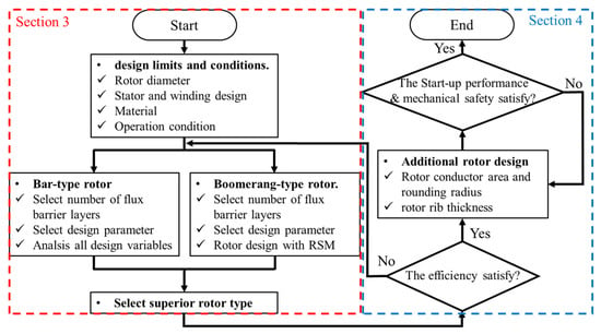
Figure 3.
Design algorithm for a 4-pole 37 kW LS-SynRM.
In Section 4, the basic rotor design is conducted, and the superior rotor type is selected. Figure 4a shows the shape of the bar-type rotor, which has straight flux barriers. Two rotors were designed, one with and one without core notches. Figure 4b shows the boomerang-type rotor, which features curved flux barriers. Two cases of the boomerang-type rotor were designed based on selected design variables.

Figure 4.
Shape of the LS-SynRM rotor and its design variables: (a) bar-type rotor; (b) boomerang-type rotor.
Due to the fewer design variables, all possible configurations of the bar-type rotor were analyzed to determine the optimal model. In contrast, the boomerang-type rotor design involved three variables. Given the large number of possible configurations for the boomerang-type rotor, the response surface methodology (RSM) was used to reduce the design time required. Due to the characteristics of LS-SynRMs, which start up with the squirrel cage, the motor must be capable of reaching a synchronous state even when accounting for the maximum external inertia moment. The maximum external inertia moment can be calculated using Equation (6) [4,23].
Here, J is the external inertia moment, and P is the rated power of the motor. The iron losses of the motor can be separated into hysteresis losses and eddy current losses. For calculating iron losses through transient FEA, Bertotti’s loss model was employed. Equation (7) represents the expression developed by Lin et al. based on Bertotti’s iron loss model [24].
Kh is the hysteresis loss coefficient, Kc is the eddy current loss coefficient, f is the supply frequency, and Bm is the peak magnetic flux density within the core material. For a conservative motor design, the operating temperature was increased by 10 °C compared to the operating temperature of a four-pole, 37 kW IM that achieves IE3 efficiency. Additionally, a 10% margin was applied to the stray losses and mechanical losses in the design process to calculate rotor damping. Mechanical and stray load losses were experimentally estimated as 1.35% of the rated output. Table 1 shows the design specifications for the LS-SynRM, including the stator core and winding details, and Figure 5 shows the shape of the stator and windings.

Table 1.
37 kW LS-SynRM design specifications and conditions.

Figure 5.
Shape of the stator core and windings for 37 kW LS-SynRM FEA.
3.1. Bar-Type Rotor Design
Prior research exists on the design of bar-type rotors with straight flux barriers and consideration of maximum external inertia. In this paper, the design of the bar-type rotor was carried out by referencing the rotor shape and design techniques from previous studies [9,25,26]. To design the SynRM rotor, the number of flux barriers must be determined. If there are too few flux barriers, it may be difficult to create a sufficient inductance gap, and the lack of rotor conductor bars can make it challenging to achieve start-up performance. On the other hand, if there are too many flux barriers, the thickness of the flux barriers and segments decreases, leading to increased saturation of the rotor core and higher leakage flux through the flux barriers, which ultimately reduces the inductance gap.
Due to its operating characteristics, the LS-SynRM exhibits different load currents at the same output depending on the rotor geometry. In this case, the load current is influenced by the difference between the d-axis and q-axis inductances, as expressed in Equation (1). However, the actual inductance during motor operation is affected by the degree of rotor flux saturation, which varies with the load current. Therefore, predicting performance solely based on rotor geometry cannot accurately reflect the motor’s behavior during operation. To address this issue, this study compared characteristics through transient FEA by varying the number of rotor flux barriers, thereby enabling more accurate prediction of motor performance under operating conditions.
Throughout the analysis, the quantity of rotor conductors remained constant, and the ratio between the thickness of the flux barriers and the thickness of the segments between flux barriers was also maintained. Figure 6 shows the rotor shape and flux density of the bar-type model according to the flux barrier layers, and Table 2 presents the variations in efficiency, power factor, and inductance gap according to the number of flux barrier layers. It was confirmed that as the number of flux barriers increases, the inductance gap becomes larger, while the load current decreases inversely with the inductance difference. Consequently, the reduction in load current leads to improvements in both efficiency and power factor. The flux density distribution in Figure 6 shows that the average flux density decreases as the number of rotor flux barriers increases. A saturated flux density above approximately 1.8 T extends the effective length of the d-axis flux path and increases the magnetic reluctance. In the cases of the four-layer and five-layer rotors, local saturation occurred in the inner flux path of the rotor, which increased the d-axis inductance and adversely reduced the inductance gap. Accordingly, for both bar-type designs, a six-layer rotor was selected.
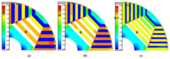
Figure 6.
Rotor shape and flux density of bar-type rotor models according to flux barrier layers: (a) 4-layer; (b) 5-layer; (c) 6-layer.

Table 2.
Bar-type rotor characteristics according to the number of flux barrier layers.
Two design parameters were selected for the optimal design of the rotor. The first parameter is the distance from the first flux barrier to the motor shaft (Wshaft), and the other is the ratio between the thickness of the flux barrier and the segment (kw). Since there are only two design variables, analyses were conducted across the entire possible design range. The design range for Wshaft is from 11 mm to 18 mm, and the design range for kw is from 0.4 to 0.6. Figure 7 shows the efficiency and PF according to the design variables. Bar-type models both without and with core notch rotors show similar trends in efficiency and PF. Therefore, the point at which both models achieve the highest efficiency and PF values was selected as the bar-type model’s final design point. The final design results of the bar-type rotor show that the outcomes of the two models are identical, with a Wshaft of 16 mm and a Kw of 0.6.
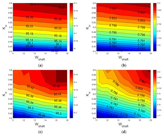
Figure 7.
Efficiency and power factor according to the design variables: (a) efficiency of the bar-type model without a notch; (b) PF of the bar-type model without a notch; (c) efficiency of the bar-type model with a notch; (d) PF of the bar-type model with a notch.
3.2. Boomerang-Type Rotor Design
To select the boomerang-type rotor’s number of flux barrier layers, we analyzed the characteristic changes corresponding to the number of flux barriers. Due to the geometric characteristics of the boomerang-type rotor, the number of flux barriers was reduced by one layer compared to the bar-type model, so only four-layer and five-layer models were analyzed. In order to assess the characteristic changes based on the number of flux barriers, the distance between the first and last flux barriers was kept constant, and the total thickness of the flux barriers was uniformly maintained across all models. Figure 8 shows the flux density and flux line of boomerang-type rotor models according to flux barrier layers, and Table 3 presents the resulting characteristic changes for the boomerang-type motor based on the number of flux barriers. Unlike the bar-type rotor, the boomerang-type rotor shows a tendency for the inductance gap to decrease as the number of flux barrier layers increases. As shown in Figure 8, the thickness at the ends of the rotor conductor bars decreases as the number of flux barrier layers increases, which indicates an increase in leakage current in the ribs. As the leakage current increases, the inductance gap decreases, leading to an increase in load current and saturation of the motor core. Consequently, the increase in core saturation of the rotor and stator teeth is observed in the five-layer rotor compared to the four-layer rotor. As shown in Table 3, the difference in the inductance gap increases the load current under the same load operation, which results in a decrease in efficiency and power factor. Therefore, for the boomerang-type rotor, the four-layer rotor was selected, which demonstrated superior electromagnetic characteristics.
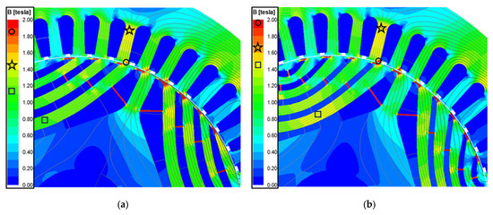
Figure 8.
Flux density and flux line of boomerang-type rotor models according to flux barrier layers: (a) 4-layer model; (b) 5-layer model.

Table 3.
Boomerang-type rotor characteristics according to the number of flux barrier layers.
A sensitivity analysis was conducted to select the design parameters for the boomerang-type rotor. The design variables subjected to the sensitivity analysis include four parameters: segment width (Wseg), barrier end width (Wbe), barrier center width (Wbc), and the width between the shaft and the first barrier (Wshaft), as shown in Figure 4b. The curvature of the flux barriers in the boomerang-type rotor is determined by the combination of these parameters. Table 4 presents the design variable values of the baseline model used for the sensitivity analysis, while Figure 9 shows the changes in electromagnetic characteristics resulting from variations in the design variables.

Table 4.
Default values of the basic model for the sensitivity analysis of the boomerang-type rotor.
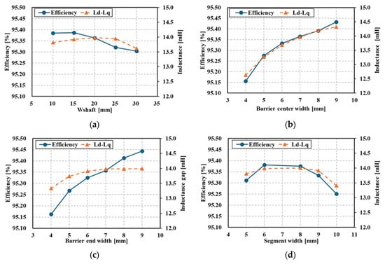
Figure 9.
Result of sensitivity analysis: (a) width between shaft and first flux barrier; (b) barrier center width; (c) barrier end width; (d) segment width.
Among the design variables, Wbc and Wbe exhibit the highest sensitivity. As Wbc increases, the q-axis inductance decreases, leading to an increase in the inductance gap, which in turn decreases the load current and improves efficiency, as shown in Equation (1). In the case of Wbe, while it did not have a significant impact on the inductance gap compared to Wbc, increasing Wbc widened the rotor conductor bar, reducing leakage in the rib and resulting in a slight increase in the inductance gap. Consequently, the load current decreased, which led to improved efficiency. On the other hand, when Wshaft increased from 10 mm to 25 mm, the length of the d-axis flux path decreased, thereby increasing the inductance gap. However, beyond 25 mm, saturation occurred at the front of the last flux barrier, increasing leakage flux and ultimately resulting in a decrease in the inductance gap and efficiency. Similarly, when Wseg exceeded 6 mm, the d-axis inductance could no longer increase, limiting further increases in the inductance gap, and beyond 9 mm, the saturation at the front of the flux barrier increased, leading to a decline in efficiency.
The variable with the highest sensitivity is Wbc; however, adjusting Wshaft and Wseg is necessary to secure Wbc. Additionally, as Wbe significantly affects efficiency, a detailed design that includes all design variables is essential. Therefore, the following two cases, which encompass all design variables, were selected:
- XA1: Wshaft, XB1: Wbc/(Wbc + Wseg), XC1: Wbe/Wbc;
- XA2: Wshaft, XB2: Wbc, XC2: Wseg, Wbe is same with Wbc.
Since the LS-SynRM requires transient FEA for characteristic analysis, including asynchronous operation, reducing computational cost is essential. Therefore, the boomerang-type rotor was designed using the RSM, which is advantageous for multi-objective optimization with a limited number of data samples [27,28,29,30,31,32]. Table 5 shows the analysis range of the design variables for RSM. Equation (8) represents the second-order regression function used for RSM, with the constants and coefficients of the regression function presented in Table 6 [33,34,35].

Table 5.
Range of design variables for the RSM.

Table 6.
Constants and coefficients of the second-order regression function for RSM.
The aim of the detailed design using RSM is to maximize both efficiency and power factor. Figure 10 and Table 7 show the results of the RSM design, comparing the predicted design outcomes from RSM with the electromagnetic analysis results of the designed models obtained through FEA. When comparing the predicted values from RSM with the results from FEA, the error in efficiency was 1%p, and the error in power factor was less than 2.5%, confirming the validity of the design predictions made using RSM.
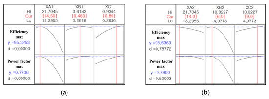
Figure 10.
RSM results for the boomerang-type rotor: (a) Case 1; (b) Case 2.

Table 7.
Results of the RSM and its comparison with FEA.
Table 8 presents the comparison between the performance predicted by the RSM and FEA, analyzing the prediction accuracy. Considering the differences in the design variable and characteristics unit, efficiency, and power factor, the Normalized Mean Absolute Error (NMAE) was employed to evaluate the prediction error, while the Coefficient of Determination (R2) was used to assess the accuracy of trend analysis between the design parameters and performance. The NMAE used in this paper was calculated according to Equation (9) [36,37].

Table 8.
Analysis of the prediction of RSM.
Here, y is the FEA result, while is the predicted value. A larger NMAE indicates a greater error between predicted values and FEA results. Empirically, values below 0.1 are regarded as highly accurate predictions, while values between 0.1 and 0.2 are considered practically acceptable. In Case 1, the prediction of efficiency and power factor was not at a highly accurate level, but it was still at a practically useful level. In contrast, Case 2 showed NMAE values below 0.1 for both efficiency and power factor, indicating highly accurate predictions.
For R2, values above 0.9 indicate excellent explanation for trends, while values between 0.7 and 0.9 suggest moderate predictive capability. In Case 1, the R2 value was around 0.8, indicating a moderate level of prediction. Case 2, however, yielded results very close to the ideal value of 1, confirming that the trend of performance variation with parameter changes was very well predicted.
3.3. Design Results and Selection of the Final Rotor Type
Figure 11 shows the flux density of the four designed four rotors, while Figure 12 shows the flux density and flux lines of the boomerang-type rotor model’s stator teeth and rotor rib, and Table 9 presents the characteristics calculated through electromagnetic FEA of these models.
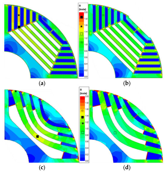
Figure 11.
Flux density of four rotor types in LS-SynRMs: (a) bar-type without notch rotor; (b) bar-type with notch rotor; (c) boomerang-type Case 1 rotor; (d) boomerang-type Case 2 rotor.
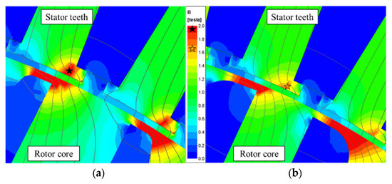
Figure 12.
Flux density and flux lines of the boomerang-type rotor model’s stator teeth and rotor rib: (a) boomerang-type Case 1 rotor; (b) boomerang-type Case 2 rotor.

Table 9.
Electromagnetic characteristics of the rotor types.
Upon reviewing the design results of the bar-type rotor, it is evident that the saliency ratio and the inductance gap remain minimal, regardless of the presence of core notches. This leads to a negligible variation in load current magnitude, resulting in similar losses across different components, which ultimately fails to produce a significant impact on the efficiency and power factor.
Conversely, the boomerang-type rotor demonstrates a marked difference between the Case 1 and Case 2 models. Although the Case 2 model contains fewer flux barriers compared to the bar-type rotor, it achieves a comparable inductance difference while maintaining lower saturation in the d-axis flux path, thereby reducing iron losses. In comparison to the Case 2 model, the Case 1 model exhibits a rapid reduction in the thickness of the rotor conductor bars as they approach the rib. A decrease in the thickness of the rotor conductor bars results in increased leakage flux at the ribs, which subsequently reduces the inductance gap and elevates the load current. The rise in load current intensifies the saturation of the stator teeth. Increased saturation of the stator teeth leads to a higher total harmonic distortion (THD) of the current, which, in turn, increases ohmic losses in the rotor conductor bars, ultimately leading to a reduction in efficiency.
Among the four rotor models, the ones that met the target efficiency were the bar-type with notch model and the boomerang-type Case 2 model. Considering manufacturability, the bar-type with notch model, which utilizes straight flux barriers, appears to be a more favorable choice. However, considering the target efficiency of 95.6% with a margin and the potential efficiency reduction caused by the conductor bar design discussed in Section 4, the boomerang-type Case 2, which exhibited the highest efficiency, was finally selected.
4. Detailed Design of the Boomerang-Type Rotor
Through the rotor designs, the rotor with the highest efficiency was selected. However, for the actual manufacturing of the motor, it is necessary to verify not only the performance at a synchronous state but also the start-up performance, and the mechanical safety regarding stresses during production and operation must also be confirmed. Figure 13 shows the design variables for the detailed design, focusing on start-up performance and mechanical safety.
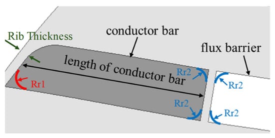
Figure 13.
Design variables for start-up performance and mechanical safety.
4.1. Length of the Conductor Bar
To ensure that the LS-SynRM reaches a synchronous speed, it is crucial to reduce the rotor resistance, which inherently means increasing the area of the rotor conductors. This can be achieved by adjusting the thickness and length of the conductor bars. However, increasing the thickness of the rotor bars narrows the d-axis flux path, leading to higher saturation in the rotor core, which in turn reduces d-axis inductance and negatively impacts electromagnetic characteristics. Therefore, only the length of the conductor bars should be adjusted to achieve the desired synchronous performance [9,25].
To analyze the start-up performance relative to the length of the conductor bars, simulations were conducted under a load torque 1.25 times the rated torque and with the maximum external inertia moment. The range of analysis spanned 15–30 mm. Figure 14 presents the start-up analysis results based on the length of the conductor bars. When the length of the rotor conductor bars is less than 25 mm, the motor exhibits pulsations below synchronous speed, whereas it reaches synchronous speed at lengths of 25 mm or greater. Although the time to reach synchronous speed decreases as the length of the rotor conductor bars increases, considering manufacturability and cost, the minimum length of 25 mm was selected.
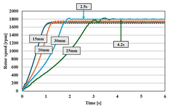
Figure 14.
Start-up performance according to rotor conductor bar length.
4.2. Conductor Bar Rounding and Rib Thickness
To ensure the mechanical safety of the LS-SynRM rotor, a detailed design was conducted focusing on the rounding radius of the conductor bars adjacent to the rib (Rr1) and the thickness of the rib (Rt), which experience the highest stress during rotor rotation. An analysis of Rr1 was conducted for values ranging from 0.5 to 2 mm, while Rt was analyzed for values between 0.5 and 1.2 mm. Figure 15 presents the results of the electromagnetic analysis, highlighting the variations in load current and rotor ohmic loss, which are most affected by changes in Rr1 and Rt. In Figure 15a, it can be observed that while the change in load current with respect to Rr1 is minimal, the variation with respect to Rt is significantly larger, with an increase in Rt leading to a rise in load current. Conversely, Figure 15b shows that the rotor’s ohmic loss is more sensitive to changes in Rr1 than in Rt, with a larger Rr1 resulting in a reduction in rotor ohmic loss.

Figure 15.
Changes in electromagnetic characteristics according to Rt and Rr adjacent to the rib: (a) load current; (b) rotor ohmic loss.
Figure 16 shows the efficiency of the LS-SynRM according to the Rr1 and Rt, while Figure 17 shows the stiffness analysis results for the motor with the final selected values of Rr and Rt. The stiffness analysis was conducted at 2000 rpm, a speed higher than the rated speed, to ensure a conservative safety evaluation. Additionally, the density of the rotor conductor bar was increased by 1.5 times in the analysis to account for the rotor’s end-ring structure. The safety factor (SF), which is used to assess mechanical safety, was calculated using Equation (10), with a target SF value of greater than 2 [22].
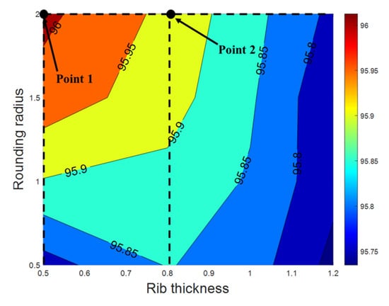 Here, σtenssile is the tensile yield strength, and σmax is the maximum equivalent stress. In Figure 16, the highest efficiency is observed at the point at which Rr is 2 mm and Rt is 0.5 mm. However, as shown in the stiffness analysis results in Figure 17a, SF at this point is 1.5, which falls short of the target SF. To address the insufficient safety margin, a new point with a larger Rt value was selected. The second chosen point is at an Rr of 0.8 mm and an Rt of 2 mm. The stiffness analysis results for the second model are shown in Figure 17b, where the SF is 2.6, meeting the target value. Therefore, the final selection for the Rr and Rt values was made based on the second model.

Figure 16.
Changes in electromagnetic characteristics according to Rt and Rr adjacent to the rib.
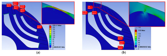
Figure 17.
Mechanical stress distribution: (a) Rt 0.5 mm, Rr 2 mm; (b) Rt 0.8 mm, Rr 2 mm.
To prevent rotor damage during the insertion of the conductor into the rotor, it is also necessary to round the edges of the conductor bars and flux barriers adjacent to the side bridge (Rr2). Figure 18 shows the changes in load current and efficiency according to the Rr2 of the conductor bars and flux barriers adjacent to the side bridge. The design range for Rr2 was set to 0.5–2.5 mm, taking into account the thickness of the conductor bars. Across this design range, the variation in load current was observed to be a maximum of 0.35 Arms, and the efficiency varied by only 0.02%p, indicating minimal impact on the electromagnetic characteristics due to changes in Rr. Therefore, considering manufacturability, the Rr adjacent to the side bridge was finalized at 2.5 mm.

Figure 18.
Changes in electromagnetic characteristics according to Rt and Rr2.
4.3. 37 kW LS-SynRM Final Model
Figure 19 shows the rotor shape, magnetic flux density distribution, and structural analysis results obtained using the previously selected conductor bar length, Rr, and Rt values. When analyzed under the same conditions as the previous simulations, the SF reached 3.1, exceeding the target of 2. Additionally, as shown in Figure 19c, it can be confirmed that the maximum deformation of the rotor is less than 0.016 mm. Figure 20 shows the efficiency and power factor of the final model under various load conditions, while Table 10 details the electromagnetic characteristics at a rated load. Both Figure 20 and Table 10 account for the previously identified margins for load current and iron losses. The efficiency at the rated load is 95.6%, achieving the target IE4 efficiency rating with a margin.
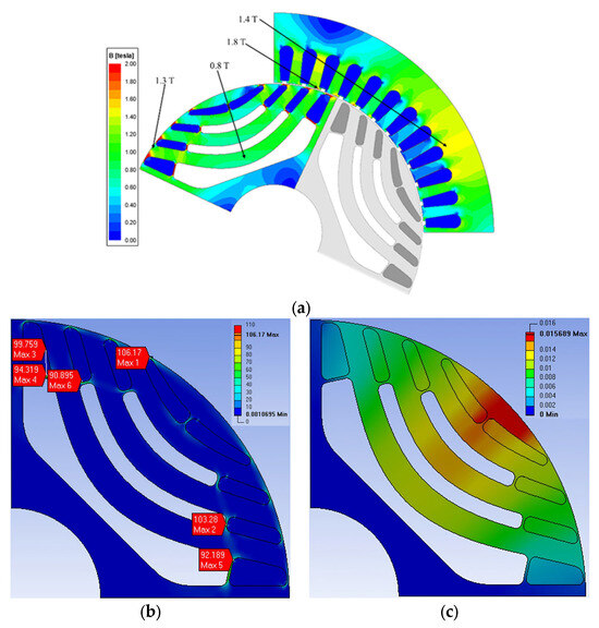
Figure 19.
Rotor shape and flux density of the final model: (a) shape and flux density; (b) result of stiffness analysis; (c) result of deformation analysis.
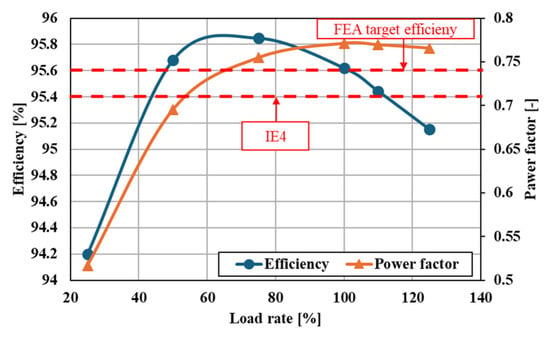
Figure 20.
Efficiency and power factor according to the load rate.

Table 10.
Electromagnetic characteristics of the final model at the rated power.
5. Experimental Results
An experimental test was conducted to validate the LS-SynRM design. Figure 21 shows the experimental test setup constructed for evaluating the performance of the 37 kW LS-SynRM and the rotor core of the experimental prototype. A servo motor and torque sensor were connected for load application and output power measurement, while a power meter was employed to measure the motor’s load current, efficiency, and power factor. To minimize measurement errors in motor characteristics, ten repeated tests were carried out at the rated load, and the averaged results were obtained. A comparison between these experimental results and the FEA predictions is summarized in Table 11.
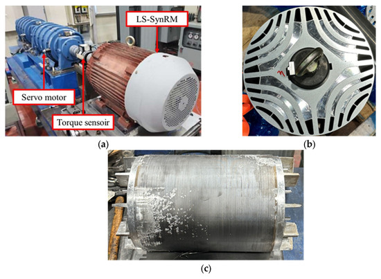
Figure 21.
Experimental test setup: (a) test bed; (b) rotor core of prototype; (c) rotor prototype completed rotor conductor bar die casting.

Table 11.
Experimental results and comparison with FEA results.
Compared with the measured experimental values, the FEA results showed a 1.7% lower load current and a 2% higher power factor. However, the experimentally measured efficiency was approximately 0.2%p higher than the FEA prediction. In Figure 22, the current and voltage waveforms measured using an oscilloscope are compared with those obtained from the FEA. Unlike the FEA, where an ideal sinusoidal input voltage without harmonics is applied, the experimental results show that the input voltage contains harmonics. Although the fundamental component of the load current was larger in the experimental measurements, the peak value obtained from the FEA was higher due to the influence of harmonics. As mentioned earlier, the FEA assumes an ideal input voltage, and differences in damping caused by mechanical and stray losses can lead to discrepancies in both the magnitude of the current and the harmonic content. Nonetheless, the motor satisfied the target IE4-class efficiency requirement of at least 95.4%.
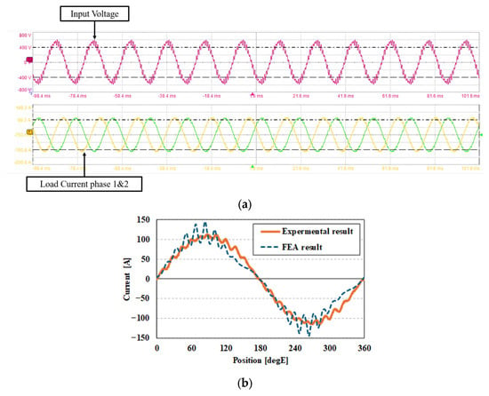
Figure 22.
Comparison between experimental measurements and FEA results: (a) input voltage and load current measured through an oscilloscope; (b) load current comparison between measured waveform and FEA waveform.
6. Conclusions
This study aims to design a four-pole 37 kW LS-SynRM for industrial applications that meets IE4 efficiency standards. To achieve this goal, we first analyzed the characteristics of the motor by categorizing its operating conditions into synchronous and asynchronous states and identified parts requiring improvement to enhance efficiency. Subsequently, we designed two bar-type rotors and two boomerang-type rotors based on different flux barrier geometries and selected the superior rotor type configuration based on efficiency criteria. It was observed that, due to their geometric properties, boomerang-type rotors possess fewer flux barriers than bar-type rotors but facilitate a greater difference in d-axis and q-axis inductances owing to their shorter d-axis magnetic path lengths. To ensure start-up performance and mechanical reliability, detailed designs were conducted concerning the Rr of conductor bars and flux barriers, as well as the Rt. As a result, the 2D FEA of the designed motor achieved an efficiency of 95.6% at the rated power, exceeding the IE4 standard with a margin, while the SF also satisfied the target value of above 2. Furthermore, performance testing confirmed that the motor efficiency exceeded the target efficiency, thereby validating the effectiveness of the motor design.
Through this study, it was confirmed that the boomerang-type rotor is more advantageous than the bar-type rotor in securing a sufficient inductance gap. In addition, rotor design parameters for the boomerang-type rotor were derived with high prediction accuracy using the RSM. In future work, torque ripple—an important factor in the highly nonlinear characteristic—will be added as a design objective to develop a more sophisticated optimal design methodology.
Author Contributions
Methodology, C.-S.K.; Formal analysis, C.-S.K. and S.-H.K.; Investigation, C.-B.P.; Resources, C.-B.P. and J.-B.L.; Writing—original draft, C.-S.K.; Project administration, H.-W.L. All authors have read and agreed to the published version of the manuscript.
Funding
This work was supported by the Korea Institute of Energy Technology Evaluation and Planning (KETEP) and the Ministry of Trade, Industry & Energy (MOTIE) of the Republic of Korea (Project No. RS-2023-00232593/Development of common base technology for medium power industrial motors).
Data Availability Statement
The original contributions presented in this study are included in the article. Further inquiries can be directed to the corresponding author.
Conflicts of Interest
The authors declare no conflict of interest.
References
- KS C IEC 60034-30-1; Rotating Electrical Machines—Part 30-1: Efficiency Classes of Line Operated AC Motors (IE Code). Korean Agency for Technology and Standards: Eumseong, Republic of Korea, 2024.
- Gregor, R. Induction Motors: Applications, Control and Fault Diagnostics; IntechOpen: Rijeka, Croatia, 2015. [Google Scholar] [CrossRef]
- Patel, M. Shipboard Electrical Power Systems, 2nd ed.; CRC Press: Boca Raton, FL, USA, 2021. [Google Scholar] [CrossRef]
- Kersten, A.; Liu, Y.; Pehrman, D.; Thiringer, T. Rotor design of line-start synchronous reluctance machine with round bars. IEEE Trans. Ind. Appl. 2019, 55, 3685–3696. [Google Scholar] [CrossRef]
- Xie, Y.; Pi, C.; Li, Z. Study on Design and Vibration Reduction Optimization of High Starting Torque Induction Motor. Energies 2019, 12, 1263. [Google Scholar] [CrossRef]
- Fuchsloch, J.F.; Finley, W.R.; Walter, R.W. Next Generation NEMA Premium® Motors Substantially Lower Operating Costs. In Proceedings of the 2006 Record of Conference Papers—IEEE Industry Applications Society 53rd Annual Petroleum and Chemical Industry Conference, Philadelphia, PA, USA, 11–15 September 2006; pp. 1–7. [Google Scholar]
- Almeida, A.T.; Ferreria, F.J.T.E.; Fong, J.A.C.; Brunner, C.U. Electric Motor Standards, Ecodesign and Global Market Transformation. In Proceedings of the 2008 IEEE/IAS Industrial and Commercial Power Systems Technical Conference, Clearwater Beach, FL, USA, 4–8 May 2008; pp. 1–9. [Google Scholar]
- Subramanian, M.; Devarajan, N.; Deivasahayam, S.M.; Ranganathan, G. Review on Efficiency Improvement in Squirrel Cage Induction Motor by using DCR Technology. J. Electr. Eng. 2009, 60, 227–236. [Google Scholar]
- Kim, H.; Kang, J.; Kim, J.; Ahn, J.; Yun, I.; Lee, J.; Noh, Y. Design and Analysis of Line-Start Synchronous Reluctance Motor Considering the Maximum Inertia and Power Factor. IEEE Trans. Ind. Appl. 2023, 59, 5908–5918. [Google Scholar] [CrossRef]
- Hu, Y.; Chen, B.; Xiao, Y.; Shi, J.; Li, X.; Li, L. Rotor Design and Optimization of a Three-Phase Line-Start Synchronous Reluctance Motor. IEEE Trans. Ind. Appl. 2021, 57, 1365–1374. [Google Scholar] [CrossRef]
- Liu, C.-T.; Shih, P.-C.; Cai, Z.-H.; Yen, S.-C.; Lin, H.-N.; Hsu, Y.-W.; Luo, T.-Y.; Lin, S.-Y. Rotor Conductor Arrangement Designs of High-Efficiency Direct-on-Line Synchronous Reluctance Motors for Metal Industry Applications. IEEE Trans. Ind. Appl. 2020, 56, 4337–4344. [Google Scholar] [CrossRef]
- Liu, H.-C.; Lee, J. Optimum Design of an IE4 Line-Start Synchronous Reluctance Motor Considering Manufacturing Process Loss Effect. IEEE Trans. Ind. Electron. 2018, 65, 3104–3114. [Google Scholar] [CrossRef]
- Liu, H.-C.; Hong, H.-S.; Cho, S.; Lee, J.; Jin, C.-S. Bubbles and Blisters Impact on Diecasting Cage to the Designs and Operations of Line-Start Synchronous Reluctance Motors. IEEE Trans. Magn. 2017, 53, 8202504. [Google Scholar] [CrossRef]
- Kim, H.; Park, Y.; Oh, S.-T.; Jang, H.; Won, S.-H.; Chun, Y.-D.; Lee, J. A Study on the Rotor Design of Line Start Synchronous Reluctance Motor for IE4 Efficiency and Improving Power Factor. Energies 2020, 13, 5774. [Google Scholar] [CrossRef]
- Farhadian, M.; Moallem, M.; Fahimi, B.; Dehkordi, B.M.; Sahebzamani, M. Alternate Rotor Design for Line-Start Synchronous Reluctance Motor with Minimum Use of Copper. IEEE Access 2024, 12, 73–84. [Google Scholar] [CrossRef]
- Rao, P.; Chen, Y.; Goldberg, M.L.; Jones, B.; Cropp, J.; Hester, J. United States Industrial and Commercial Motor System Market Assessment Report, Volume 1: Characteristics of the Installed Base; Lawrence Berkeley National Laboratory, U.S. Department of Energy: Berkeley, CA, USA, 2021. [CrossRef]
- Smit, Q.; Sorgdrager, A.; Wang, R.-J. Design and optimisation of a line-start synchronous reluctance motor. In Proceedings of the 24th Southern African Universities Power Engineering Conference, Vereeniging, South Africa, 26–28 January 2016. [Google Scholar]
- Aguba, V.; Muteba, M.; Nicolae, D.V. Transient analysis of a start-up synchronous reluctance motor with symmetrical distributed rotor cage bars. In Proceedings of the 2017 IEEE AFRICON, Cape Town, South Africa, 18–20 September 2017; pp. 1290–1295. [Google Scholar]
- Kersten, A. Efficiency Investigation of Line Start Synchronous Reluctance Motors. Master’s Thesis, Department of Energy and Environment, Chalmers University of Technology, Göteborg, Sweden, 2017. [Google Scholar]
- Gamba, M.; Armando, E.; Pellegrino, G.; Vagati, A.; Janjic, B.; Schaab, J. Line-start synchronous reluctance motors: Design guidelines and testing via active inertia emulation. In Proceedings of the 2015 IEEE Energy Conversion Congress and Exposition (ECCE), Montreal, QC, Canada, 20–24 September 2015; pp. 4820–4827. [Google Scholar]
- Kim, M. A Study on the Design Method and Operating Characteristics Analysis for EV Traction Induction Motor. Ph.D. Thesis, Department of Energy and Environment, Hanyang University, Seoul, Republic of Korea, 2013. [Google Scholar]
- Gamba, M.; Pellegrino, G.; Vagati, A. Design of Non Conventional Synchronous Reluctance Machine. Master’s Thesis, Pelitecnico di Torino, Department of Energy, Turin, Italy, 2017. [Google Scholar]
- IEC 60034-12; Rotating Electrical Machines—Part 12: Starting Performance of Single-Speed Three-Phase Cage Induction Motors. BSI: London, UK, 2024.
- Lin, D.; Zhou, P.; Fu, W.; Badics, Z.; Cendes, Z. A dynamic core loss model for soft ferromagnetic and power ferrite materials in transient finite element analysis. IEEE Trans. Magn. 2004, 40, 1318–1321. [Google Scholar] [CrossRef]
- Kang, J.; Kim, J.; Park, Y.; Kim, C.; Lee, J.; Kim, H. Optimization of SynRM for High Efficiency Considering Airgap Flux Density Shape. In Proceedings of the 2022 IEEE 20th Biennial Conference on Electromagnetic Field Computation, Denver, CO, USA, 24–26 October 2022; pp. 1–2. [Google Scholar]
- Moghaddam, R.R. Synchronous Reluctance Machine Design. Master’s Thesis, Royal Institute of Technology (KTH), Stockholm, Sweden, 2007. [Google Scholar]
- Ortega-Casanova, J. CFD study on mixing enhancement in a channel at a low Reynolds number by pitching a square cylinder. Comput. Fluids 2017, 145, 141–152. [Google Scholar] [CrossRef]
- Gilmour, S.G. Response surface designs for experiments in bioprocessing. Biometrics 2006, 62, 323–331. [Google Scholar] [CrossRef] [PubMed]
- Mourabet, M.; El Rhilassi, A.; El Boujaady, H.; Bennani-Ziatni, M.; Taitai, A. Use of response surface methodology for optimization of fluoride adsorption in an aqueous solution by Brushite. Arab. J. Chem. 2017, 10, S3292–S3302. [Google Scholar] [CrossRef]
- Khodaei, B.; Sobati, M.A.; Shahhosseini, S. Optimization of ultrasound-assisted oxidative desulfurization of high sulfur kerosene using response surface methodology (RSM). Clean Technol. Environ. Policy 2016, 18, 2677–2689. [Google Scholar] [CrossRef]
- Liu, J.; Wang, J.; Leung, C.; Gao, F. A Multi-Parameter Optimization Model for the Evaluation of Shale Gas Recovery Enhancement. Energies 2018, 11, 654. [Google Scholar] [CrossRef]
- Yolmeh, M.; Jafari, S.M. Applications of response surface methodology in the food industry processes. Food Bioprocess Technol. 2017, 10, 413–433. [Google Scholar] [CrossRef]
- Jung, Y.S.; Kwak, Y.S.; Lee, J.; Jin, C.S. Study on the optimal design of PMa-SynRM loading ratio for achievement of ultra-premium efficiency. IEEE Trans. Magn. 2017, 53, 8001904. [Google Scholar] [CrossRef]
- Kim, S.-I.; Hong, J.-P.; Kim, Y.-K.; Nam, H.; Cho, H.-I. Optimal design slotless-type PMLSM considering multiple response by response surface methodology. IEEE Trans. Magn. 2006, 42, 1219–1222. [Google Scholar]
- Saha, S.; Choi, G.-D.; Cho, Y.-H. Optimal rotor shape design of LSPM with efficiency and power factor improvement using response surface methodology. IEEE Trans. Magn. 2015, 51, 8113104. [Google Scholar] [CrossRef]
- Yang, H.; Gong, S.; Liu, Y.; Lin, Z.; Qu, Y. A Multi-task Learning Model for Daily Activity Forecast in Smart Home. Sensors 2020, 20, 1933. [Google Scholar] [CrossRef]
- Piotrowski, P.; Rutyna, I.; Baczyński, D.; Kopyt, M. Evaluation Metrics for Wind Power Forecasts: A Comprehensive Review and Statistical Analysis of Errors. Energies 2022, 15, 9657. [Google Scholar] [CrossRef]
Disclaimer/Publisher’s Note: The statements, opinions and data contained in all publications are solely those of the individual author(s) and contributor(s) and not of MDPI and/or the editor(s). MDPI and/or the editor(s) disclaim responsibility for any injury to people or property resulting from any ideas, methods, instructions or products referred to in the content. |
© 2025 by the authors. Licensee MDPI, Basel, Switzerland. This article is an open access article distributed under the terms and conditions of the Creative Commons Attribution (CC BY) license (https://creativecommons.org/licenses/by/4.0/).