Abstract
Photovoltaic/Thermal (PV/T) systems are a technology designed to simultaneously convert solar energy into both electrical and thermal energy. The overall conversion efficiency of these systems can be significantly enhanced by effectively cooling the photovoltaic (PV) module. To this end, this paper presents a comparative experimental study of a PV panel under three distinct configurations: operating with a no cold plate, with an ordinary cold plate, and with a spiral coil cold plate. The system’s photo-thermoelectric efficiency was evaluated by measuring key parameters, including the PV panel’s surface temperature, electrical power output, and the water tank temperature. The results indicate that the spiral coil configuration demonstrated a marked superiority in temperature regulation over the baseline case, achieving a maximum temperature reduction of 13.8 °C and an average reduction of 10.74 °C. Furthermore, a stable temperature drop exceeding 10 °C was maintained for 74.07% of the experimental duration. When compared to the ordinary cold plate, the spiral coil configuration continued to exhibit superior performance, delivering maximum and average temperature drops of 3.6 °C and 2.16 °C, respectively, while sustaining a cooling advantage of over 2 °C for 66.67% of the test period. These findings conclusively demonstrate that the spiral coil cold plate is the most effective configuration for enhancing the system’s overall performance.
1. Introduction
The confluence of dwindling fossil fuel reserves, volatile energy prices, and escalating global energy demand has rendered the development of clean and renewable energy sources a critical priority. Among these, solar energy is distinguished as the most abundant and widely distributed resource, presenting significant opportunities for its utilization and technological advancement [1,2,3,4,5]. The conversion of solar radiation into usable energy is primarily achieved through two principal methods: photothermal conversion for heat and photovoltaic conversion for electricity. Solar photovoltaic panels are instrumental in the latter, facilitating the direct conversion of solar irradiance into electrical energy. However, it is well-established that the energy conversion efficiency of PV panels is inversely correlated with their operating temperature. For instance, each 1 °C rise in module temperature results in an efficiency decrease of approximately 0.5% for crystalline silicon cells and 0.25% for amorphous silicon cells [6,7,8]. Consequently, to mitigate these thermal-induced performance losses and maintain optimal operating conditions, substantial research has been devoted to developing effective cooling strategies for PV panels, thereby improving their overall conversion efficiency [9,10,11,12,13,14,15].
The concept of a hybrid solar Photovoltaic/Thermal system was first proposed by Wolf in 1976 [16]. This innovative design integrates photovoltaic and thermal functions to capture and utilize the waste heat from the rear of the PV panel. This process serves a dual purpose: it maintains the module’s operating temperature closer to its optimal point and simultaneously enhances the system’s overall solar energy utilization efficiency. In the decades that followed, this concept has been the subject of extensive research. For instance, Dupeyrat et al. [17] conducted a comparative analysis between a PV/T system and separate, co-located PV and thermal collectors. Their results demonstrated that for a given surface area and under identical climatic conditions, the integrated PV/T system yielded more total energy, proving advantageous from both an energy production and an efficiency standpoint. Investigating its application in colder climates, Qiu et al. [18] found that a PV/T system for building energy supply outperformed conventional systems, achieving a 10% increase in the heating Coefficient of Performance (COP) and a 72.3% reduction in life-cycle costs. Similarly, Abuska [19] evaluated the combined efficacy of a residential PV/T installation under the actual climatic conditions of Bangkok, concluding that the system is highly effective for supplying both electricity and heat in tropical regions.
In the field of solar Photovoltaic/Thermal systems, a variety of cooling technologies have been developed to effectively regulate the operating temperature of the PV module and thereby mitigate thermal-induced efficiency degradation. These technologies can be broadly classified into two categories: passive cooling and active cooling, based on the requirement for external power input to drive the cooling process. Passive cooling techniques leverage natural physical phenomena, such as natural convection, thermal radiation, and the latent heat of phase change, for heat dissipation. Their primary advantage lies in the absence of external energy input, which ensures system simplicity and zero parasitic power consumption. Among the most common strategies is the attachment of cooling fins or heat sinks to the PV backsheet. By augmenting the rear surface area, fins enhance natural convection and radiative heat transfer to the surroundings, thereby lowering the module’s temperature. However, the heat dissipation capacity of this method is inherently limited and highly contingent upon ambient conditions such as wind speed and temperature. Another prominent passive technique is the integration of Phase Change Materials (PCMs). PCMs are encapsulated at the rear of the PV module; when the module temperature reaches the melting point of the PCM, it absorbs a significant amount of latent heat during its solid-to-liquid phase transition. This process can effectively “clamp” the module’s temperature at a lower, stable level for a period. Despite their high heat storage density, the finite thermal capacity of PCMs means the cooling effect ceases once the material is fully melted, and the subsequent heat release during the night can be slow. Overall, while passive solutions are attractive for certain low-heat-flux applications due to their low cost and high reliability, their limited heat dissipation ceiling makes them insufficient for the high-efficiency cooling required under high-irradiance conditions. In contrast, active cooling technologies require an external power source to drive the forced circulation of a cooling medium, enabling highly effective heat removal. Forced air cooling is a relatively simple active approach that uses fans to direct airflow over the module’s backsheet or through internal channels. However, due to the low specific heat capacity and thermal conductivity of air, its heat transfer efficiency is typically modest, and it is often accompanied by acoustic noise and the fan’s energy consumption.
By comparison, active liquid cooling is widely recognized as the most effective method for PV module thermal management. This technology utilizes a liquid coolant (such as water) that is forcibly circulated through a cold plate in direct contact with the PV backsheet to carry away heat. This approach not only yields significant cooling but also allows the captured thermal energy to be recovered and utilized, thereby forming a co-generating Photovoltaic/Thermal system that vastly improves the overall solar energy utilization efficiency. Owing to its superior performance and potential for energy co-generation, active liquid cooling has become the mainstream research direction in the field of PV/T systems, with numerous scholars conducting in-depth research into its structural configurations and performance characteristics [20,21]. Y. Yu compared the heat harvesting capacity and electrical conversion efficiency of the conventional vertical channel cold plate and the new grid channel cold plate [22]. The results show that the new cold plate has a significant improvement in heat collection capacity and electrical conversion efficiency. M. Rajvikram uses a phase change material and combines it with external fins to regulate the temperature of the photovoltaic panels to improve the efficiency of the photovoltaic panels. The effect of temperature control on PV efficiency and the importance of choosing a cooling method are then discussed [23]. Shixiang Lu utilizes a new solar PV/T module as a condenser that can be used to meet the cooling needs of buildings. Experimental results show that the new solar PV/T module is able to cool stably during summer nights with average COP reference values between 1.8 and 2.1 [24]. Ghasemian Mehran added spoilers to the cold plate flow channel to improve the performance of the solar PV/T device. The results show that triangular runners with spoilers are more effective than circular and rectangular ones, but the economic efficiency will be reduced [25]. Xie Yujie formed a double serpentine runner by rearranging the runner baffles. This study solved the problem of high pressure loss in conventional runners due to improper baffle arrangement [26]. Some scholars have found that in the cooling of photovoltaic panels, using a 0.02% Al2O3/ZnO hybrid nanofluid as the cooling medium can effectively reduce the temperature of the panels [27]. Additionally, some researchers have employed spray cooling methods for photovoltaic panels. They conducted comprehensive experimental analyses on nozzle quantity, diameter, and spray distance, demonstrating that an optimized spray cooling system can significantly enhance photovoltaic performance in high-temperature and arid climate zones [14].
In summary, while the majority of research on solar PV/T systems has focused on the optimization of cold plate channel geometry, comparatively less attention has been given to the integration of flow turbulators within these channels. Furthermore, many studies tend to evaluate thermal and electrical efficiencies independently, rather than assessing a combined or overall system performance metric. Crucially, a direct, parallel comparison and quantitative assessment of the performance of a PV module under no cooling, conventional flat-plate cooling, and turbulator-enhanced flat-plate cooling configurations under identical operating conditions is notably absent from the current literature. The present study is therefore designed to fill this void by conducting a systematic experimental evaluation of these three distinct configurations.
In this study, an indoor experimental platform was constructed to investigate a solar PV/T system. The system was optimized by integrating a spoiler into the flow channel of the cold plate, and its performance was comprehensively evaluated based on key metrics including PV panel temperature, thermal energy collection, electrical power output, and overall efficiency.
2. Experimental Equipment and System
To ensure a controlled experimental environment and enable an accurate performance evaluation of the solar PV/T device, an indoor test facility was constructed. The experimental apparatus, depicted schematically in Figure 1, is composed of a solar simulator, a photovoltaic module, a liquid-cooled cold plate, a thermal storage tank, a circulation pump, a flow meter, shut-off valves, a multi-point data logger, and various temperature sensors and piping. The system is functionally divided into two primary subsystems: a coolant circulation loop for thermal energy transfer and a photovoltaic circuit for power generation. To minimize thermal losses to the ambient environment, all piping and the water storage tank were thoroughly insulated.
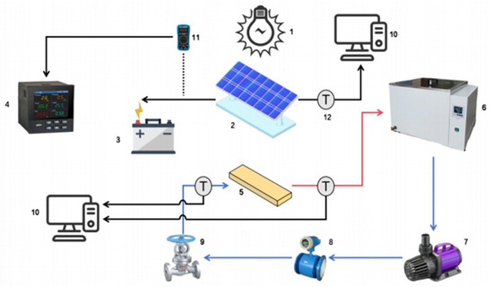
Figure 1.
Schematic diagram of the experimental system. 1. solar simulator; 2. photovoltaic modules; 3. battery; 4. multi-point recorder; 5. liquid-cooled panels; 6. heat storage tank; 7. circulation pump; 8. flowmeter; 9. shut-off valve; 10. computer; 11. current and voltage dual-display meter; 12. Thermocouple.
Conventional microchannel cold plates, which typically feature simple, open, straight-flow configurations, suffer from inherent limitations such as a restricted heat transfer area and insufficient thermal efficiency. To overcome these drawbacks, the integration of turbulator elements within the flow channels is a proven method for heat transfer enhancement. Turbulators effectively increase turbulence intensity, promote fluid mixing, and disrupt the thermal boundary layer, thereby significantly improving the convective heat transfer process. Grounded in this principle, this study designed a spiral coil cold plate with the objective of achieving highly efficient heat dissipation for the solar photovoltaic system. The spiral coil cold plate, serving as the core component of the experimental system, is constructed entirely from aluminum. Key design parameters of this cold plate are detailed in Table 1. To enhance heat exchange efficiency, an irregularly wound aluminum spiral coil was integrated into the flow channel to act as a turbulator. This coil was then sealed within the channel using a high-temperature industrial sealant (Kafuter) and a thin aluminum cover plate. The internal structure and the finished product are depicted in Figure 2. For the purpose of comparative analysis, a cold plate fabricated without the internal spiral coil is defined as the ‘ordinary cold plate’ in subsequent experiments. Given the large surface area of the PV module, two spiral coil cold plates were connected in series to ensure adequate cooling coverage. When the working fluid flows through the channel of the cold plate, the spiral coil turbulator effectively alters its flow regime, transitioning it from a relatively stable laminar state to a complex turbulent flow. To fundamentally explain the superior thermal performance of the spiral coil cooling plate demonstrated in this study, an analysis based on the fundamental principles of fluid mechanics and heat transfer is necessary. According to the typical flow velocities and pipe dimensions set in the experiment, it can be reasonably predicted that the coolant flow regime within the channels is turbulent. Under turbulent conditions, the fluid mixing is more thorough, which effectively disrupts and thins the stable thermal boundary layer and significantly reduces the convective thermal resistance. Consequently, the spiral coil geometry induces secondary flows that enable a much higher convective heat transfer coefficient compared to a straight channel, even at the same mass flow rate. From a manufacturing standpoint, the process for the ordinary cold plate is mature and relatively low-cost. In contrast, the fabrication of the spiral coil cold plate is more complex due to the addition of the internal turbulator, which invariably increases its initial manufacturing cost. Therefore, a critical question from an economic perspective is whether the performance gains offered by the spiral coil design are sufficient to offset its higher initial investment over the system’s life cycle. Answering this would require a detailed techno-economic analysis. It is important to note, therefore, that the performance enhancements reported in the present study are assessed purely from a thermo-technical perspective and do not encompass a life-cycle cost analysis.

Table 1.
Main parameters of cold plate.
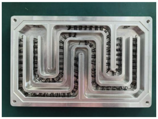
Figure 2.
Schematic diagram of spiral coil cold plate.
A key component of the experimental setup was a solar simulator, which was constructed using tungsten-halogen lamps. The light source for this study was a 1000 W, double-ended Philips tungsten-halogen lamp (Model: R7s). This lamp is characterized by a color temperature of 3000 K, with physical dimensions including a total length of 189 mm, an effective light-emitting length of 150 mm, and a filament diameter of 8 mm. Prior to conducting the experiments, a calibration procedure was performed to determine the average irradiance incident upon the PV panel’s surface. The radiation intensity was measured at multiple points across the panel area. A measurement at each point was considered final when the reading stabilized or exhibited only minimal fluctuations. The arithmetic mean of these stabilized measurements from all points was then taken as the definitive radiation intensity for the experiment.
During experimental operation, the working fluid is drawn from a constant temperature water tank and propelled by a circulation pump through a flow meter into the cold plate. Within the cold plate, the fluid absorbs heat from the photovoltaic panel before returning to the tank, thus completing a closed-loop thermal cycle. To quantify the heat transfer, thermocouples are strategically installed in the pipeline at the immediate inlet and outlet of the cold plate. A data logger continuously monitors and records the temperature changes at these two points. Upon the completion of each experimental run, a sufficient cooling period is observed to ensure both the photovoltaic panel and the cold plate return to the designated initial temperature, thereby maintaining consistent starting conditions for subsequent tests. A photograph of the experimental bench is presented in Figure 3.
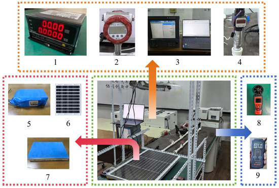
Figure 3.
Schematic diagram of the experimental system. 1. DW-81 type current and voltage double display meter; 2. GTLWCY4 Turbine Flowmeter; 3. multi-point recorder; 4. tachometer; 5. accumulators; 6. photovoltaic panel; 7. cold plate; 8. model ST8916 Anemometer; 9. VT110 solar radiometer.
The comprehensive performance evaluation of the solar PV/T system was based on the measurement of several key parameters: solar irradiance, PV panel temperature, electrical power output, working fluid flow rate, and the corresponding inlet and outlet fluid temperatures. The primary instruments and their specifications for measuring these parameters are detailed in Table 2.
Table 2.
Main parameter measuring instruments.
3. Experimental Results and Analysis
3.1. System Performance Evaluation Index
The performance evaluation of the PV/T experimental system encompasses two primary domains: photothermal (thermal) performance and photovoltaic (electrical) performance. A critical consideration in this analysis is that the enhancement of heat transfer is often accompanied by an increase in hydraulic resistance. Compared to the ordinary cold plate, the complex internal geometry of the spiral coil turbulator inevitably leads to a higher pressure drop. Consequently, a greater amount of pumping power is required to circulate the working fluid. This parasitic energy consumption partially offsets the electrical power gain achieved through temperature reduction. Ideally, a comprehensive evaluation would be based on the system’s net energy output (defined as the total electrical generation minus the pump power consumption). However, for the scope of this study, the differential in pump power consumption was not included in the comparative analysis for two primary reasons. First, the flow rate and piping configuration were held constant across all comparative experiments. Second, the rated power of the circulation pump (50 W) is considered negligible relative to the system’s total power generation. Therefore, the performance comparisons presented herein are based on the gross electrical and thermal outputs.
To ensure a fair comparison between the different cooling configurations and to guarantee the repeatability of the results, all experiments in this study were conducted under strictly controlled laboratory conditions. This approach also ensured that the total solar irradiance on the PV/T module’s aperture surface met the specified experimental requirements. The ambient environmental parameters were maintained as follows: air velocity below 1.0 m/s, ambient temperature within 25 °C, atmospheric pressure at approximately 0.1 MPa, and a relative humidity of 45%. Furthermore, to mitigate the influence of random environmental factors such as dust and dirt accumulation, the surface of the photovoltaic panel was thoroughly cleaned before the start of each experimental run. The PV/T system was considered to have reached a quasi-steady state operating condition when the fluctuations of all measured parameters remained within the specified ranges detailed in Table 3 for the entire test duration. This rigorous control protocol was implemented to ensure the reliability and accuracy of the collected experimental data.
Table 3.
Acceptable fluctuation range.
The overall performance of the PV/T system is evaluated based on two key metrics: its photothermal efficiency and its photovoltaic efficiency. These quantitative indicators provide a comprehensive framework for assessing the system’s dual energy generation capabilities.
3.1.1. Photothermal Performance
- Total system heat collection;
The total system heat collection can be calculated by Equation (1):
where is the mass of the mass in the thermal storage tank, is the constant pressure specific heat capacity of the mass, is the initial temperature of the thermal storage tank, and is the final temperature of the thermal storage tank.
- 2.
- Cumulative system thermal efficiency;
The cumulative system thermal efficiency can be expressed as the ratio of the total heat collection of the system to the total solar irradiation, as shown in Equation (2):
where is the total system heat collection, is the total irradiance of the solar simulator, and is the light harvesting area of the photovoltaic module.
3.1.2. Photovoltaic Performance
- Instantaneous power output;
The instantaneous power output can be calculated by Equation (3):
where is the instantaneous output voltage of the photovoltaic module and is the instantaneous output current of the photovoltaic module.
- 2.
- Instantaneous power conversion;
The instantaneous power conversion is defined as the ratio of the PV module output to the total solar radiation received by the PV module, as shown in Equation (4):
where is the solar simulator irradiation intensity and is the total area of the PV module.
- 3.
- Cumulative electricity generation
The cumulative electricity generation of the PV/T collector system is defined as the cumulative output of the PV module, as shown in Equation (5):
3.1.3. Overall Performance
- Overall energy efficiency;
The overall energy efficiency is shown in Equation (6) [28]:
where is the coverage factor, which is the ratio of the total area of the PV module to the light harvesting area of the PV module.
- 2.
- Overall PV/T efficiency;
Recognizing that electrical energy is a higher grade of energy than thermal energy due to its greater stability and thermodynamic quality, a more comprehensive metric is required to accurately evaluate the overall solar energy utilization of the system. To address this, Huang carried out a theoretical analysis, and proposed the concept of overall PV/T efficiency, which is expressed as Equation (7) [29]:
where is the power generation efficiency of the ordinary thermal power plant and is 38%.
3.2. Experimental System Error Analysis
During the experimental process, multiple factors, including the measurement instrumentation, methodology, environmental conditions, and operator influence, can introduce uncertainties, leading to discrepancies between measured values and their true values. To ensure the reliability and accuracy of the experimental results, a systematic uncertainty analysis was conducted in this study. According to uncertainty theory, the uncertainty of a directly measured quantity is primarily associated with the precision of the instrument, whereas the uncertainty of an indirectly calculated quantity must be determined using an uncertainty propagation formula. Following the methodology for uncertainty analysis provided in previous research [30], a detailed calculation and assessment of the experimental uncertainties were performed to validate the scientific credibility of the data.
In this study, several measures were implemented to ensure the accuracy of the measurements. All experimental instruments were calibrated prior to use. To ensure the reliability and reproducibility of the results, the experiment for each cooling device configuration was performed in triplicate on three typical clear-sky days with similar meteorological conditions. The reported data represent the average of these three trials. This replication strategy minimizes the impact of random errors inherent in a single trial, thereby enhancing the credibility of the findings. The uncertainties for the directly measured and indirectly calculated physical quantities were analyzed using Equations (8) and (9), respectively [31]. This rigorous approach to uncertainty analysis ensures the reliability and accuracy of the data. This analysis indicates that the potentially h roviding a robust scientific basis for the subsequent performance evaluation.
where is the error of the i-th directly measured physical quantity, is the measurement instrument accuracy, is the error of the indirectly measured physical quantity, is the number of directly measured physical quantities related to the indirectly measured physical quantity.
The uncertainty analysis results for the directly measured physical quantities are summarized in Table 4. The corresponding uncertainties for the indirectly calculated physical quantities are presented in Table 5. As indicated by the analysis, the relative uncertainty for each parameter falls within an acceptable range, thereby satisfying the precision requirements for this study.
Table 4.
Uncertainty analysis results table.
Table 5.
Uncertainty of Performance Metrics.
3.3. Net Power Gain and Sensitivity Analysis
To evaluate the effective energy performance of the active cooling system, this study introduces two key metrics: total power gain and net power gain. These metrics are calculated using Equations (10) and (11).
where is the net power gain, is the photovoltaic panel output power, is the output power without cooling configuration, and is the pump power consumption.
Furthermore, to investigate the impact of pump power consumption on the overall system benefit, a sensitivity analysis was conducted. Considering the typical power range of small circulation pumps, three representative power consumption values were selected for this analysis: 25 W (representing a high-efficiency pump scenario), 50 W (the typical value used in this study), and 75 W (representing a high-resistance or lower-efficiency pump scenario). The corresponding net power gain was then calculated for each of these cases, with the results summarized in Table 6.
Table 6.
Net power gain and sensitivity analysis.
As indicated by the data in the table, when a typical 50 W pump is employed, the spiral coil cold plate still provides a substantial net power gain of 2389.95 kJ. This confirms that the system delivers a net positive energy benefit under these standard operating conditions, which validates the decision made in this study to neglect the differential in pump power for the primary performance comparison. However, the analysis also highlights the system’s sensitivity to this parameter. If the system were to require a 75 W pump, the net power gain would be substantially reduced to 1579.95 kJ. Should the pump power consumption increase further, the net power gain advantage of the spiral coil system over the conventional cooling scheme would continue to diminish. This analysis indicates that the potentially higher pressure drop must be compensated for by employing a high-efficiency pump. A successful PV/T system design necessitates co-optimization, where the pursuit of high heat transfer efficiency must be balanced against the need for low flow resistance. The findings of this study establish a clear performance constraint for system design: the thermal performance advantage offered by the spiral coil translates into a meaningful net energy gain only if the total parasitic power consumption is maintained below a certain threshold.
3.4. Analysis of Experimental Results
The integration of a cold plate system is a critical strategy for the thermal management of PV panels. It effectively lowers the module’s operating temperature, promotes a more uniform surface temperature distribution, and consequently mitigates the detrimental impact of the hot spot effect. Furthermore, by reducing thermal stress on the module components, the application of cold plate technology enhances the long-term reliability and extends the operational lifespan of the PV system.
To investigate the influence of different cold plate structures on system performance, a comparative experimental study was designed. The experiments were conducted under the following fixed conditions: a solar irradiance of 950 ± 25 W/m2, an ambient temperature of 24.5 °C, a zero-degree collector inclination angle, and an ambient wind speed of 0.5 m/s. Deionized water served as the cooling medium with a constant flow rate of 1.1 L/min. Three distinct configurations were tested over a 540-min duration for each experiment: (1) a baseline case with no cold plate, (2) a conventional flat-plate cold plate, and (3) a spiral coil cold plate. The schematic diagram of the experimental setup is shown in Figure 4. This study systematically analyzes and compares key performance indicators—including temperature variation characteristics, instantaneous power generation, cumulative heat collection, cumulative power generation, and overall solar efficiency—to comprehensively evaluate the impact of each cold plate configuration on the PV/T system’s performance.
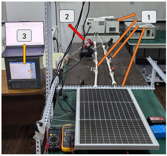
Figure 4.
Schematic diagram of the experimental setup. 1. Thermocouple; 2. Flowmeter; 3. Data logger.
3.4.1. Photovoltaic Panel Temperature
The effect of the cold plate structure on the PV panel temperature is shown in Figure 5. This figure demonstrates the impact of the cold plate structure on the regulation of the working temperature of the PV panels. The quantitative relationship between the cold plate structure and the temperature distribution of the PV panels can be observed through systematic comparative analysis.
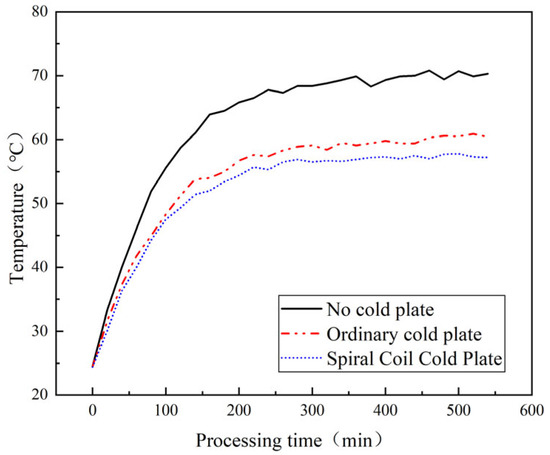
Figure 5.
PV panel temperature comparison curves.
Analysis of the experimental data reveals distinct thermal profiles for the three tested configurations. The temperature evolution can be characterized by three primary stages: an initial heating stage (0–30 min), a rapid temperature rise stage (30–100 min), and a stabilization stage (200–540 min). In the initial stage, the temperature profiles for all three conditions were nearly identical, exhibiting a rapid and uniform increase. However, upon entering the rapid rise phase, the temperature of the baseline (no cold plate) module continued to increase at a high rate, whereas the heating rates for the ordinary cold plate and spiral coil cold plate configurations decelerated significantly due to active thermal dissipation. As the experiment progressed, the systems approached a quasi-steady state. During the stabilization stage, the baseline module’s temperature plateaued at approximately 70 °C, while the ordinary cold plate and spiral coil cold plate stabilized at significantly lower temperatures of approximately 61 °C and 57 °C, respectively.
A quantitative analysis further underscores the superiority of the spiral coil cold plate. Compared to the baseline case, the spiral coil cold plate achieved a maximum temperature reduction of 13.8 °C and an average temperature reduction of 10.74 °C. Furthermore, a temperature drop exceeding 10 °C was sustained for 74.07% of the experimental period, which translates to a theoretical power output increase of 5.37%. The spiral coil cold plate also demonstrated a clear advantage over the ordinary cold plate, delivering a maximum temperature reduction of 3.6 °C and an average temperature reduction of 2.16 °C. This cooling benefit of over 2 °C was maintained for 66.67% of the test duration, corresponding to a 1.08% theoretical increase in power output. Collectively, these results confirm that the spiral coil cold plate effectively suppresses the temperature rise of the PV module, maintaining it within a lower operating range and thereby enhancing the system’s overall energy conversion efficiency.
The effect of the cold plate structure on the total heat collection of the system is shown in Figure 6.
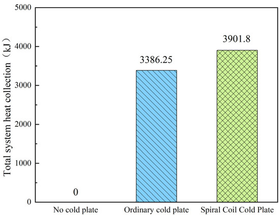
Figure 6.
Comparison chart of total system heat collection.
The analysis of cumulative heat collection highlights the profound impact of the cold plate configuration on the system’s thermal performance. The no cold plate yielded a negligible thermal energy capture of approximately 0 kJ, confirming its ineffectiveness for solar thermal utilization. The integration of a ordinary cold plate marked a substantial improvement, with the system’s cumulative heat collection reaching 3386.25 kJ, thereby underscoring the fundamental role of the cold plate in the heat recovery process. Notably, the spiral coil cold plate configuration demonstrated superior performance, achieving a total heat collection of 3901.8 kJ. This represents a significant 15.22% enhancement compared to the conventional cold plate. This superior performance is primarily attributed to the design advantages of the helical flow path. The spiral geometry increases the effective heat transfer surface area and promotes greater fluid turbulence, which collectively enhance the heat exchange coefficient. Furthermore, this structure facilitates a more uniform fluid distribution across the plate, effectively suppressing the formation of localized hot spots and contributing to a higher overall thermal efficiency for the system.
The effect of cold plate structure on the collector efficiency of the system is shown in Figure 7.
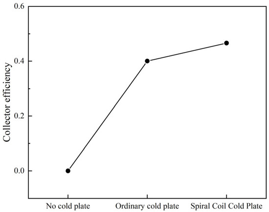
Figure 7.
System collector efficiency comparison chart.
The analysis of the collector’s thermal efficiency, as depicted in the figure, reveals a clear performance hierarchy among the three configurations. As expected, the baseline configuration demonstrated a thermal efficiency of nearly 0%, confirming its inability to effectively capture solar thermal energy. The integration of a ordinary cold plate resulted in a substantial increase in thermal efficiency to 40.04%, which unequivocally demonstrates the essential role of the cold plate in the thermal energy recovery process. Notably, the spiral coil cold plate configuration achieved the highest performance, with a thermal efficiency of 46.6%. This represents a significant 16.38% relative improvement over the ordinary cold plate. This enhanced performance is attributed to the superior heat transfer characteristics of the spiral coil design. Its geometry effectively increases the heat transfer surface area and optimizes the fluid flow path, thereby promoting more effective thermal exchange and leading to a significant improvement in the overall system performance.
3.4.2. Electricity Generation and Efficiency
The comparison curve of instantaneous power generation of the cold plate structure is shown in Figure 8.
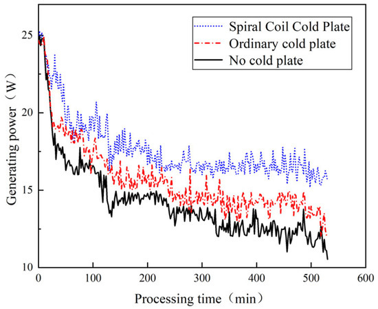
Figure 8.
Comparison chart of instantaneous power generation.
Analysis of the instantaneous power generation reveals distinct performance characteristics among the three experimental configurations. During the initial stage (0–30 min), all three systems exhibited high power output as they operated close to their optimal low-temperature efficiency. The spiral coil cold plate achieved the highest peak power of 25.18 W, followed by the ordinary cold plate is 24.97 W and the baseline configuration is 24.96 W. In the subsequent stabilization phase, the instantaneous power of all configurations decreased to varying degrees due to thermal degradation. The spiral coil cold plate maintained the most stable and highest output, with power consistently in the 17–20 W range. The ordinary cold plate performed intermediately, sustaining an output of 14–16 W, while the baseline configuration showed the most significant decline, with its power gradually decreasing to 11–13 W. Minor fluctuations observed in the data are within the acceptable range and are primarily attributed to small variations in the solar simulator’s irradiance and systematic instrumental error.
A quantitative comparison further highlights these differences. Compared to the baseline configuration, the spiral coil cold plate provided an average power increase of 3.4 W (max: 5.81 W), with the power gain exceeding 3 W for 66.42% of the experimental duration. When compared to the ordinary cold plate, the spiral coil still delivered a significant advantage, with an average power increase of 1.99 W (max: 4.67 W) and a power gain of over 2 W for 51.32% of the test period. These results conclusively demonstrate that the superior thermal management provided by the spiral coil structure directly translates into a significant and sustained enhancement of the PV system’s instantaneous power generation.
The effect of the cold plate structure on the total system power generation is shown in Figure 9.
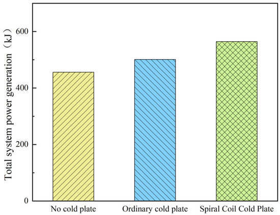
Figure 9.
Comparison chart of total system power generation.
The cumulative electrical energy generation, a key metric for overall performance, shows a clear dependence on the cooling configuration, as illustrated in the figure. The no cold plate produced the lowest total energy, yielding only 455.9 kJ. The integration of a ordinary cold plate significantly improved performance, increasing the total power generation to 500.76 kJ, which underscores the critical role of active cooling in enhancing photovoltaic conversion efficiency. Notably, the spiral coil cold plate demonstrated the most superior performance, with a cumulative power generation of 564.05 kJ. This represents a 23.72% improvement over the baseline and a substantial 12.64% increase compared to the ordinary cold plate. This significant enhancement is attributed to the superior thermal management provided by the spiral coil structure. It facilitates a more uniform temperature distribution across the panel, effectively suppressing the formation of localized hot spots. As a result, the photovoltaic module operates consistently within a more optimal temperature range, leading to a higher overall photovoltaic conversion efficiency and greater cumulative energy yield.
The effect of the cold plate structure on the power generation efficiency of the system is shown in Figure 10.
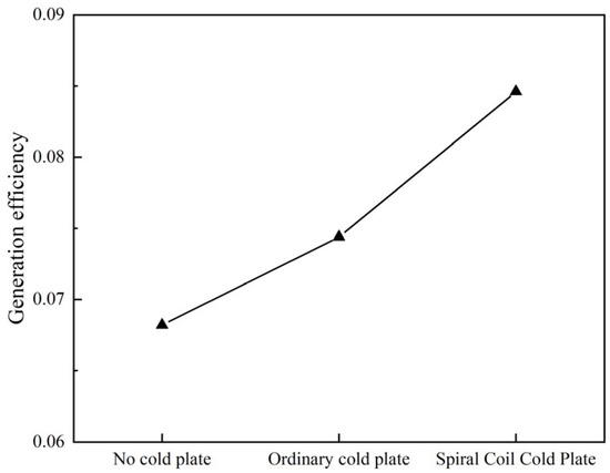
Figure 10.
Comparison chart of system power generation efficiency.
The analysis of the system’s photovoltaic conversion efficiency reveals a clear performance advantage for the actively cooled configurations. The no cold plate exhibited the lowest efficiency at 6.82%. The integration of an ordinary cold plate yielded a notable improvement, increasing the efficiency to 7.44%, thereby confirming the critical role of thermal management in optimizing PV system performance. The most significant result was achieved with the spiral coil cold plate, which reached a PV efficiency of 8.46%. This represents a substantial relative increase of 24.05% over the baseline and 13.71% over the conventional cold plate. This superior performance is a direct consequence of the unique structural design of the spiral coil, which facilitates a more uniform and efficient heat transfer mechanism. By significantly lowering the operating temperature of the PV module, this design effectively mitigates thermal degradation and maximizes the photovoltaic conversion efficiency.
3.4.3. Combined Efficiency
When the difference in electrical and thermal energy tastes is not considered, the effect of the cold plate structure on the system’s solar energy utilization efficiency is shown in Figure 11.
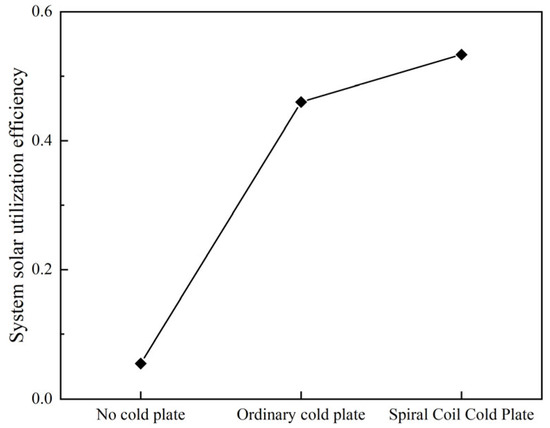
Figure 11.
Comparison chart of system overall energy efficiency.
The overall energy efficiency, which combines both thermal and electrical outputs, provides the most comprehensive measure of system performance. The no cold plate was profoundly inefficient, with an overall energy efficiency of only 5.45%, primarily due to its inability to capture thermal energy. The integration of an ordinary cold plate led to a dramatic improvement, boosting the overall energy efficiency to 45.99%, which highlights the fundamental importance of heat recovery in a PV/T system. Notably, the spiral coil cold plate achieved the highest performance, reaching an overall energy efficiency of 53.36%. This value represents a remarkable 879.08% increase over the baseline and a significant 16.03% improvement over the ordinary cold plate. This superior overall energy efficiency confirms the significant advantage of the helical coil structure, whose enhanced heat transfer capabilities elevate both the thermal and photovoltaic performance of the system.
When considering the difference in electrical and thermal energy tastes, the effect of the cold plate structure on the combined overall PV/T efficiency of the system is shown in Figure 12.
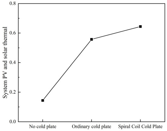
Figure 12.
Comparison of overall PV/T efficiency for different systems.
The overall PV/T efficiency, which accounts for the higher quality of electrical energy, serves as a crucial metric for evaluating the combined system performance. The no cold plate demonstrated the lowest overall efficiency at 14.35%. The introduction of an ordinary cold plate led to a substantial improvement, elevating the efficiency to 55.70%, a result that underscores the pivotal role of active cooling in enhancing the system’s combined energy output. The highest performance was achieved with the spiral coil cold plate, which yielded an overall PV/T efficiency of 64.41%. This represents a remarkable 348.85% increase over the baseline and a significant 15.64% improvement over the ordinary cold plate.
These findings demonstrate that the spiral coil cold plate structure excels at simultaneously optimizing the photovoltaic conversion process through effective cooling and maximizing thermal energy recovery. Consequently, this design provides valuable insights and a promising strategy for the advanced thermal management of solar photovoltaic systems.
4. Discussion and Conclusions
In this study, the performance of three distinct photovoltaic panel cooling configuration was experimentally investigated. A comprehensive comparative analysis was conducted based on key performance metrics, including thermal collection efficiency, electrical generation efficiency, overall solar energy utilization efficiency, and the overall photo-thermoelectric efficiency.
4.1. Comparison with Previous Studies
The spiral coil cold plate demonstrated superior performance across all evaluated metrics. These findings are in strong agreement with conclusions from prior literature regarding the benefits of optimized flow channel designs and provide robust experimental validation for them. The key contribution of this work lies in establishing reliable performance benchmarks for these fundamental designs. It quantitatively defines the precise performance gains achievable when transitioning from conventional to spiral coil cooling, thereby providing valuable reference data for the future engineering design and optimization of Photovoltaic/Thermal (PV/T) systems.
Under the specific operating conditions of this study, the spiral coil cold plate exhibited a significant advantage in temperature control. Compared to the baseline case, it achieved a maximum temperature reduction of 13.8 °C and an average reduction of 10.74 °C, with the temperature drop stably maintained above 10 °C for 74.07% of the experimental duration. In comparison to the conventional cold plate, it still delivered distinct advantages, with maximum and average temperature drops of 3.6 °C and 2.16 °C, respectively, while sustaining a cooling effect of over 2 °C for 66.67% of the test.
Most notably, when accounting for the difference in energy quality, the spiral coil cold plate achieved an overall photo-thermoelectric efficiency of 64.41%. This represents a remarkable increase of approximately 348.85% over the baseline and 15.64% over the ordinary cold plate. These data confirm that the spiral coil structure significantly optimizes photovoltaic conversion and enhances thermal energy recovery. Furthermore, this study highlights the importance of operational stability over prolonged periods as a key performance indicator for evaluating cooling technologies, offering valuable insights for the advanced thermal management design of solar photovoltaic systems.
4.2. Comparison with Mainstream Cooling Technologies
To comprehensively evaluate the contribution of the spiral coil cold plate developed in this study, it is essential to benchmark its performance against other mainstream PV/T cooling technologies reported in the literature.
Passive cooling techniques are notable for their zero parasitic power consumption. Among these, the addition of heat sinks or fins is a common strategy; however, the literature consistently reports a relatively modest temperature reduction, typically in the range of 3–7 °C, with performance being highly dependent on ambient wind conditions. In contrast, the spiral coil cold plate in this study achieved an average temperature drop of 10.74 °C, demonstrating a significant step-up in cooling efficacy. Phase Change Materials (PCMs) represent another advanced passive technology, capable of stabilizing the PV temperature at a lower level during their phase transition. However, the fundamental limitation of PCMs is their finite heat storage capacity, which can lead to a cessation of the cooling effect during prolonged operation. Therefore, relative to these passive technologies, the active liquid cooling approach of the present study offers a clear advantage in terms of sustained, high-efficiency cooling.
Within the domain of active cooling, more aggressive heat transfer enhancement techniques exist. For instance, spray cooling, which involves the direct atomized injection of liquid onto the PV backsheet, can achieve exceptionally high heat transfer coefficients. The literature reports temperature reductions as high as 15–20 °C, a range that numerically exceeds the results of the present study. This superior performance, however, comes at the cost of significantly increased system complexity, higher pumping power requirements, and potential long-term operational challenges.
The core innovation of the spiral coil cold plate proposed in this study lies in its exceptional balance of overall performance. Compared to existing technologies, our solution utilizes a structurally simple and technologically mature closed-loop system. Through a unique, optimized flow channel design, it achieves heat dissipation performance comparable to that of more complex and costly cooling technologies, while ensuring high system reliability. Notably, this approach strikes an optimal balance across three key dimensions: thermal performance, economic cost, and operational stability. This makes it particularly suitable for photovoltaic applications where cost-effectiveness and long-term reliability are paramount. This balanced design philosophy not only demonstrates significant practical engineering value but also offers a new technological pathway for the industrial application of PV cooling.
4.3. Practical Impact and Application Prospects
This study has experimentally validated the superiority of the spiral coil cold plate in enhancing PV/T system performance. Beyond the laboratory data, these findings indicate profound practical implications and significant environmental benefits.
The measured increase in electrical efficiency directly translates to greater daily electricity output. When this daily gain is accumulated over the typical 25-year operational lifespan of a photovoltaic module, the total incremental energy yield becomes substantial. More importantly, the significant amount of thermal energy recovered by the PV/T system, which can be utilized for domestic hot water or space heating, represents an energy stream that is entirely wasted in standard PV installations. Therefore, from a life-cycle perspective, a PV/T system employing effective cooling can dramatically increase the total solar energy utilization per unit of installation area. This enhanced energy production directly corresponds to a greater contribution to greenhouse gas emission reduction.
The findings of this study offer significant guidance for the operation of photovoltaic systems in hot and dusty regions, such as the Middle East and North Africa. The extreme climatic conditions typical of these areas, including sustained high temperatures and intense solar irradiance, often cause PV modules to operate at elevated temperatures. It is well-established that the accelerated degradation of module materials in high-temperature environments is a key factor leading to power decay and permanent failure. Experimentally, our proposed spiral coil cooling plate technology was verified to achieve a significant reduction in the average module operating temperature by more than 10 °C. This innovative thermal management solution not only provides an immediate boost to the PV system’s power generation efficiency but, more importantly, effectively suppresses thermally-induced degradation effects. Consequently, it extends the service life of the modules in harsh environments and significantly enhances the system’s long-term operational reliability.
4.4. Feasibility and Challenges of Large-Scale Applications
Considering the future practical application of this technology, a nuanced, case-by-case analysis is required, particularly when comparing large-scale solar farms with Building-Integrated Photovoltaic/Thermal (BIPV/T) systems.
The direct application of the spiral coil cold plate to large-scale solar farms faces formidable challenges. First, from a hydraulic standpoint, interconnecting thousands of modules would necessitate an extremely vast and complex piping network. This would lead to prohibitive pressure drops and, consequently, exorbitant parasitic pumping power, which would likely diminish or even negate the electrical gains achieved through cooling. Second, from an economic perspective, the initial capital expenditure and long-term maintenance costs for such an extensive cooling infrastructure would likely be prohibitive. Finally, and most critically, the substantial amount of low-grade thermal energy recovered would have little to no practical application, as solar farms are typically located in remote, sparsely populated areas where land is inexpensive. Therefore, we prudently conclude that for the majority of utility-scale solar farms, the proposed spiral coil cold plate may not represent a viable or practical solution.
In stark contrast, we argue that BIPV/T systems represent the ideal and most promising application scenario for this technology. In this context, the PV/T modules function not only as power generators but also as integral components of the building envelope, such as roofing or façades. This study offers several key contributions to the field of photovoltaic cooling. First, it enables the efficient recovery and utilization of thermal energy. By converting what is traditionally considered waste heat into a usable resource, the system can supply domestic hot water, support floor heating, and even power an absorption chiller for air conditioning. This energy cascade utilization model significantly reduces a building’s reliance on fossil fuels and enhances its overall energy efficiency. Second, the system design is optimized for building-integrated applications. Through a compact piping layout and rational system scaling, the pumping power consumption is successfully limited to less than 15% of the system’s total energy consumption. Notably, the experimentally validated spiral coil cold plate structure demonstrates superior heat transfer performance, achieving a substantially higher solar energy capture efficiency per unit area compared to conventional flat-plate designs. These findings provide a feasible technological pathway toward the realization of Zero Energy Buildings and hold both theoretical and practical value for advancing the energy transition in the building sector.
Therefore, the findings of this study have tangible implications for the advancement of net-zero energy building, where maximizing on-site energy generation and utilization is a primary objective.
In conclusion, this study has experimentally demonstrated the significant advantages of the spiral coil cold plate in enhancing the cooling, energy conversion efficiency, and overall performance of Photovoltaic/Thermal systems. The primary contribution of this research lies in establishing reliable performance benchmarks for several fundamental cooling configurations. It explicitly quantifies the precise performance gains achievable when transitioning from conventional to spiral coil cooling. By doing so, this study provides crucial, data-driven insights and a clear engineering basis for the future design and optimization of high-efficiency PV/T systems.
Author Contributions
R.T.: conceptualization, methodology, investigation, writing—original draft preparation, formal analysis, and visualization. Y.L.: conceptualization, methodology, validation, supervision, and writing—review and editing. S.M.: writing—review and editing, visualization, and supervision. All authors have read and agreed to the published version of the manuscript.
Funding
This research received no external funding.
Data Availability Statement
The original contributions presented in this study are included in the article. Further inquiries can be directed to the corresponding author.
Conflicts of Interest
The authors declare no conflicts of interest.
References
- Kirchhoff, C.J.; Michaud, L.; Gupta, B.; Liu, Y.; Strazzabosco, A. Exploring renewable energy transitions in energy intensive sectors: A comparative case study of solar adoption among wastewater systems in California and New York. J. Clean. Prod. 2025, 520, 146095. [Google Scholar] [CrossRef]
- Zhang, W.; Pei, G.; Zhao, B. Performance analysis of switchable radiative cooling and solar heating for building energy-saving. Energy 2025, 333, 137507. [Google Scholar] [CrossRef]
- Yildirim, B.; Ayyildiz, E.; Aydin, N. A novel intuitionistic fuzzy decision-making framework for sustainable site selection of solar panel waste recycling facilities. J. Clean. Prod. 2025, 521, 146195. [Google Scholar] [CrossRef]
- Cui, C.; Lonergan, E.K.; Sansavini, G. Policy-driven transformation of global solar PV supply chains and resulting impacts. Nat. Commun. 2025, 16, 6742. [Google Scholar] [CrossRef] [PubMed]
- Esmaeilion, F.; Soltani, M.; Garcia, A.D. Solar-driven multigeneration systems in grid-connected scheme integrated with air energy storage systems. Sustain. Energy Technol. Assess. 2025, 81, 104443. [Google Scholar] [CrossRef]
- Sandwell, P.; Winchester, B.; Mittal, S.; Markides, C.N.; Beath, H.; Nelson, J. Opportunities for decentralised solar power to improve reliability, reduce emissions and avoid stranded assets. Nat. Commun. 2025, 16, 8061. [Google Scholar] [CrossRef]
- Ma, W.; Nie, Y.; Cao, W.; Fan, Q.; Wen, J.; Zhang, Y.; Xiong, R.; Huang, C. Bioinspired, robust wood solar evaporator with scale-like surfaces for efficient solar-driven water purification and thermoelectric generation. Chem. Eng. J. 2025, 519, 165196. [Google Scholar] [CrossRef]
- Lee, J.; Farias, M.; Aparicio, H.; Li, H.; Nabavi, B.; Zhao, B.; Ahmed, F.; Li, P.; Xu, B.; Li, J.; et al. Development of boron-enhanced inconel 718 with superior thermomechanical properties for high-temperature concentrated solar power applications. Sol. Energy Mater. Sol. Cells 2025, 292, 113787. [Google Scholar] [CrossRef]
- Wang, C.; Guo, F.; Liu, H.; Wang, G. A Comprehensive Review of Research Works on Cooling Methods for Solar Photovoltaic Panels. Energies 2025, 18, 4305. [Google Scholar] [CrossRef]
- Sheikholeslami, M.; Bujasim, A.M. Efficiency enhancement of photovoltaic solar panels using hybrid cooling systems with cross-shaped fins and porous foam. Int. Commun. Heat Mass Transf. 2025, 167, 109331. [Google Scholar] [CrossRef]
- Abdelmohsen, S.H.; Alrashedy, A.; Abdelhady, S.; Rekaby, A. Enhancing PV performance using a novel water jacket and humidified air-cooling systems in arid climates. Appl. Therm. Eng. 2025, 278, 127259. [Google Scholar] [CrossRef]
- Masalha, I.; Badran, O.; Alahmer, A. Performance Enhancement of Photovoltaic Panels Using Natural Porous Media for Thermal Cooling Management. Sustainability 2025, 17, 5468. [Google Scholar] [CrossRef]
- Han, M.; Jiao, K.; Lu, L.; Jin, P.; Ma, T.; Wang, Q. PEG-based solid-solid phase change materials for passive cooling of solar photovoltaic panels. Appl. Energy 2025, 394, 126190. [Google Scholar] [CrossRef]
- Bayrak, F.; Gönül, A.; Camci, M. Thermal management of photovoltaic panels using configurations of spray cooling systems. Appl. Therm. Eng. 2025, 274, 126656. [Google Scholar] [CrossRef]
- Usman, M.; Haq, U.W.H.; Riaz, F.; Ali, M.S.; Masood, M.I.; Fouad, Y.; Chatha, S.K.; Bashir, M.N. Investigation of a novel heat extraction configuration for boosting photovoltaic panel efficiency. Case Stud. Therm. Eng. 2025, 70, 106104. [Google Scholar] [CrossRef]
- Wolf, M. Performance analyses of combined heating and photovoltaic power systems for residences. Energy Convers. 1976, 16, 79–90. [Google Scholar] [CrossRef]
- Dupeyrat, P.; Ménézo, C.; Fortuin, S. Study of the thermal and electrical performances of PVT solar hot water system. Energy Build. 2014, 68, 751–755. [Google Scholar] [CrossRef]
- Qiu, G.; Xu, Z.; Biu, X.; Yu, S. Research progress of integrated solar energy and air source heat pump heating system. Chem. Prog. 2018, 37, 2597–2604. [Google Scholar] [CrossRef]
- Abuşka, M.; Şevik, S. Energy, exergy, economic and environmental (4E) analyses of flat-plate and V-groove solar air collectors based on aluminium and copper. Sol. Energy 2017, 158, 259–277. [Google Scholar] [CrossRef]
- Zhan, S.; Zhao, X.; Zhao, S.; Yin, Y. Optimization design method for serpentine cold plates combining structural parameter tuning and topology optimization. Appl. Therm. Eng. 2025, 275, 126868. [Google Scholar] [CrossRef]
- Si, P.; Feng, Y.; Lv, Y.; Rong, X.; Pan, X.; Liu, X.; Yan, J. An Optimization Method Applied to Active Solar Energy Systems for Buildings in Cold Plateau Areas—The Case of Lhasa. Appl. Energy 2016, 194, 487–498. [Google Scholar] [CrossRef]
- Yu, Y.; Yang, H.; Peng, J.; Long, E. Performance comparisons of two flat-plate photovoltaic thermal collectors with different channel configurations. Energy 2019, 175, 300–308. [Google Scholar] [CrossRef]
- Rajvikram, M.; Sivasankar, G. Experimental study conducted for the identification of best heat absorption and dissipation methodology in solar photovoltaic panel. Sol. Energy 2019, 193, 283–292. [Google Scholar] [CrossRef]
- Lu, S.; Zhang, J.; Liang, R.; Zhou, C. Refrigeration characteristics of a hybrid heat dissipation photovoltaic-thermal heat pump under various ambient conditions on summer night. Renew. Energy 2020, 146, 2524. [Google Scholar] [CrossRef]
- Mehran, G.; Sheikholeslami, M.; Maziar, D. Performance improvement of photovoltaic/thermal systems by using twisted tapes in the coolant tubes with different cross-section patterns. Energy 2023, 279, 128016. [Google Scholar]
- Yujie, X.; Jinzhi, Z.; Emmanuel, B.; Jiang, F.; Ji, W.; Sun, L.; Zhao, K.; Yuan, Y. Exergy performance assessment of a novel air-cooled photovoltaic thermal collector with a double serpentine runner. Appl. Therm. Eng. 2024, 236, 21330. [Google Scholar]
- Shaalan, Z.; Hussein, A.; Abdullah, M. Numerical-experimental study to improve photovoltaic panel cooling by using hybrid ZnO/Al2O3 nanofluids. Case Stud. Therm. Eng. 2025, 70, 106053. [Google Scholar] [CrossRef]
- Huang, B.J. Performance evaluation of solar photovoltaic/thermal systems. Sol. Energy 2001, 70, 443–448. [Google Scholar] [CrossRef]
- Xinxiang, W.; Xin, W.; Wenjian, Z. Preparation and Application of Encapsulated Phase Change Materials; Chemical Industry Press: Beijing, China, 2009. [Google Scholar]
- Taraldsen, G.; Lindqvist, B. Conditional fiducial models. J. Stat. Plan. Inference 2018, 195, 141–152. [Google Scholar] [CrossRef]
- Mathioulakis, E.; Panaras, G.; Belessiotis, V. Estimation of uncertainties in indirect humidity measurements. Energy Build. 2011, 43, 2806–2812. [Google Scholar] [CrossRef]


Disclaimer/Publisher’s Note: The statements, opinions and data contained in all publications are solely those of the individual author(s) and contributor(s) and not of MDPI and/or the editor(s). MDPI and/or the editor(s) disclaim responsibility for any injury to people or property resulting from any ideas, methods, instructions or products referred to in the content. |
© 2025 by the authors. Licensee MDPI, Basel, Switzerland. This article is an open access article distributed under the terms and conditions of the Creative Commons Attribution (CC BY) license (https://creativecommons.org/licenses/by/4.0/).