Article

VMD-LSTM-Based Model Predictive Control for Hybrid Energy Storage Systems with Auto-Tuning Weights and Constraints

1
China Automotive Engineering Research Institute Co., Ltd., Chongqing 401122, China
2
Guangdong Automotive Test Center Co., Ltd., Foshan 528051, China
3
School of Mechanical and Electrical Engineering, Beijing Information Science and Technology University, Beijing 100192, China
4
School of Traffic and Transportation, Beijing Jiaotong University, Beijing 100044, China
*
Author to whom correspondence should be addressed.
Energies 2025, 18(21), 5559; https://doi.org/10.3390/en18215559
Submission received: 12 September 2025 / Revised: 3 October 2025 / Accepted: 16 October 2025 / Published: 22 October 2025
(This article belongs to the Section E: Electric Vehicles)

Abstract

Enhancing ultra-capacitor (UC) utilization and mitigating battery stress are pivotal for improving the energy management efficiency and service life of hybrid energy storage systems (HESSs). Conventional energy management strategies (EMSs), however, rely on fixed parameters and therefore struggle to allocate power flexibly or reduce battery degradation. This paper proposes a VMD-LSTM-based EMS that incorporates auto-tuning weight and constraint to address these limitations. First, a VMD-LSTM predictor was proposed to improve the velocity and road gradient prediction accuracy, thus leading an accurate power demand for EMS and enabling real-time parameter adaptation, especially in the nonlinear area. Second, the model predictive controller (MPC) was adopted to construct the EMS by solving a multi-objective problem using quadratic programming. Third, a combination of rule-based and fuzzy logic-based strategies was introduced to adjust the weights and constraints, optimizing UC utilization while alleviating the burden on batteries. Simulation results show that the proposed scheme boosts UC utilization by 10.98% and extends battery life by 19.75% compared to traditional MPC. These gains underscore the practical viability of intelligent, optimizing EMSs for HESSs.

1. Introduction

The rapid adoption of electric vehicles (EVs) offers a compelling pathway to reducing dependence on fossil fuels. Integrating an ultra-capacitor (UC) with a battery in hybrid energy storage systems (HESSs) under an advanced energy management strategy (EMS) creates an ideal on-board power solution [1]. A well-designed EMS can efficiently allocate power between the battery and the UC, leveraging the battery’s high energy density and the UC’s high power capability to extend the HESS lifespan [2,3].
To address this issue, various EMSs for HESSs have been proposed, including rule-based strategies (RBSs), global optimization, and instantaneous optimization [4]. While RBSs are easy to implement, they cannot guarantee optimal efficiency under intensive charge–discharge cycles [5]. Global optimization can achieve the best offline performance because it exploits the entire dataset, but its computational burden precludes online use and it is therefore employed mainly as a benchmark [6]. In contrast, instantaneous optimization techniques, which demand far less computation and memory, have become a research focus. Among them, model predictive control (MPC) [7] and intelligent control strategies [8,9] have attracted much attention. Although abundant, high-quality offline data enable robust training and subsequent online optimization of the control logic; intelligent control strategies can also hinder real-time performance. MPC has therefore become a central topic in EMS research, owing to its rolling optimization capability [10]. Current efforts converge on two complementary directions: embedding accurate predictors to supply reliable reference trajectories and regulating hyper-parameters online to enhance MPC adaptability. The former leads to prediction-based MPC, whereas the latter yields adaptive MPC. A real-time MPC-based EMS is developed by considering driving cycle prediction, improving efficiency compared with conventional MPC and fuzzy logic-, rule-based EMS [11]. In [10], a predicted-power-based MPC is proposed for HESSs and achieves ideal performance when the required power is fully known. In [12], a predictive EMS is developed for HESSs, enhancing the driving economy of fuel-cell hybrid-electric-vehicle (FCHEV) platoons through the integration of speed prediction. In practice, prediction-based MPC leverages advanced forecasting algorithms to generate trustworthy set-points for each optimization cycle, while adaptive MPC continuously retunes weights, horizons, and constraints, jointly improving responsiveness and optimality [13].
At the heart of prediction-based MPC lies the need for high quality prediction. Prediction strategies generally fall into neural networks (NNs) [14] and stochastic approaches [5,15]. For instance, a Hidden Markov Model (HMM) was used in [16] to forecast vehicle velocity based on traffic conditions; a radial basis function NN (RBF-NN) with variable parameters was developed in [17] for the same purpose; and LSTM and ARIMA predictors have been embedded in MPC strategies [18]. However, single models inevitably hit accuracy ceilings when confronted with highly nonlinear, fluctuating data. Hybrid or multi model schemes that exploit signal decomposition have therefore gained attention [19]. The variation mode decomposition (VMD)-based Long Short-Term Memory (LSTM) predictors for wave height and GNSS time series have shown that decomposition markedly outperforms a standalone LSTM [20,21,22]. By breaking the noisy, non-stationary signal into stable modes, VMD allows each LSTM to focus on a single component, yielding far higher accuracy and stability. Vehicle velocity and road slope are similarly time-varying, so VMD should improve their forecasts as well; however, no study has yet applied VMD to speed prediction.
Adaptive MPC that varies its prediction horizon, weights, and constraints can markedly boost performance [23]. For example, A non-uniform-horizon MPC was shown in [24] to reduce battery stress in HESSs. A variable weight-based MPC was developed in [25] for aircraft HESSs, optimizing the battery charge state and engine operation points. Similarly, a variable constraint MPC was proposed in [26] for wave energy converters, ensuring optimal energy harvesting by continuously reshaping the system’s safety boundaries online. These results confirm that parameter adaptation enhances MPC robustness, a principle now widely exploited in process control [27]. To ensure reliable parameter tuning, fuzzy and machine learning techniques are commonly employed. While machine learning can obtain optimal tuning, it often faces practical limitations due to prolonged convergence times. In contrast, fuzzy-based techniques, known for their robustness, are commonly used for parameter tuning [28].
However, existing MPC-based EMS for HESSs typically rely on fixed parameters and treat UC as secondary components to support energy, keeping the battery engaged throughout the entire energy management process [29,30]. The core optimization principle generally focuses on minimizing battery current fluctuations and extending battery life by considering aging effects [31,32]. However, UC can be recharged or discharged more efficiently, and their high utilization can significantly improve system efficiency and reduce the battery burden [2,33]. Although variable weight-based MPC has been applied in EMS, fixed constraints still force the battery to play a crucial role during the recovery process [34]. To fully leverage UC capabilities, it is essential to isolate the battery from being recharged in a timely manner [35,36]. For example, during the recovery process, adjusting the constraint can alleviate the burden on batteries, allowing the recovery power to flow entirely into the UC. This VMD-LSTM-based EMS can maximize UC utilization, reduce high C-rate cycling of the battery, and prolong battery lifetime simultaneously.
Given these benefits, this paper proposes a novel MPC with auto-tuning weights and constraints (MPC-ATWC) that integrates a VMD-LSTM predictor to achieve this goal efficiently.
  • The introduction of the MPC-ATWC strategy represents a significant advancement. By auto-tuning weights and constraints, this strategy not only improves energy management efficiency but also prolongs battery life.
  • The proposed VMD-LSTM model significantly improves the prediction accuracy of velocity and road gradient, thus leading to a more accurate power demand prediction.
  • A combination of rule-based and fuzzy logic-based strategies is introduced to auto-tune the weights and constraints, optimizing UC utilization while alleviating the burden on batteries.
The paper is structured as follows. Section 2 establishes the HESS model. Section 3 derives the auto-tuning weights and constraints technology. Section 4 proposes the results and discussion. Section 5 presents the conclusion.

2. System Modeling

2.1. Vehicle and HESS Structure

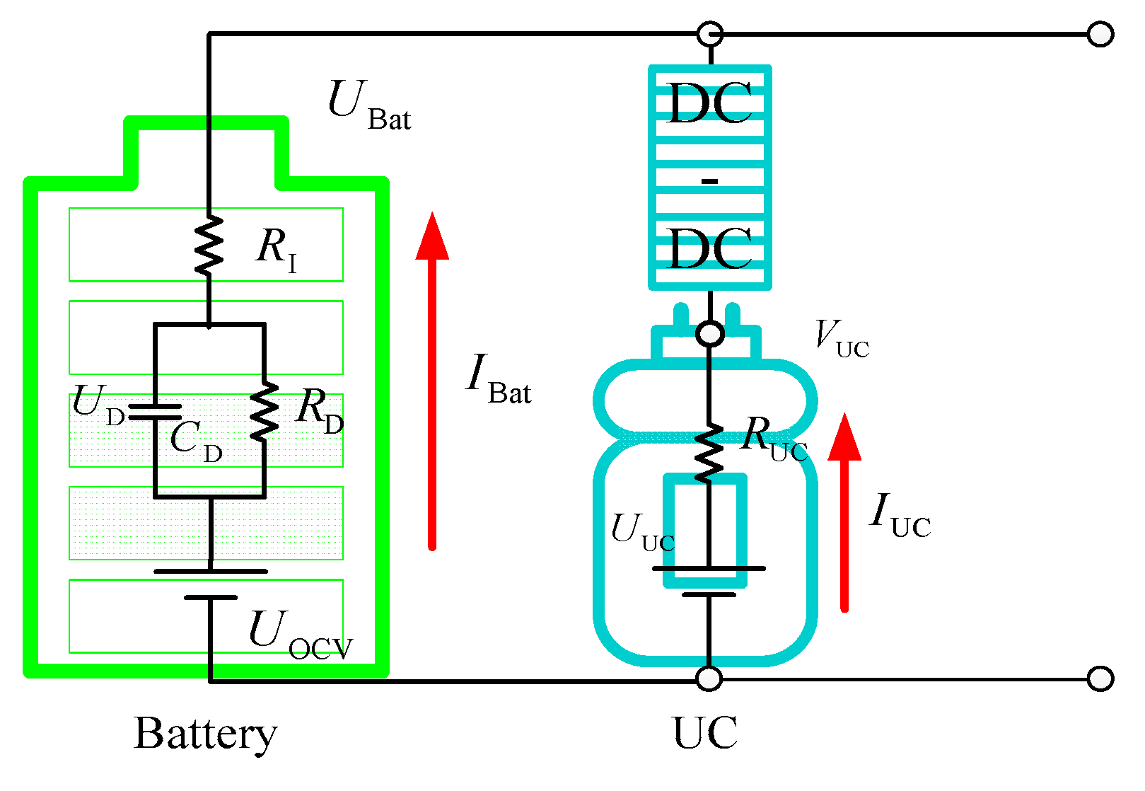
The semi-active HESS topology balances efficiency, fast load following, and low losses, making it the mainstream choice for EVs. We therefore adopt this structure for modeling and achieving flexible EMS [18], as shown in Figure 1. During the energy distribution process, the battery serves as the primary component providing base power, while the capacitor acts as a secondary device supplying high frequency and peak power, controlled by the DC-DC converter [37]. The whole EMS was controlled with the microcontroller unit (MCU).
The total power demand at any instant is supplied jointly by the battery and the UC in a defined proportion. This power demand P r e q , which accounts for the prevailing road gradient and vehicle velocity, can expressed as follows:
P r e q = M g f v cos α + M g v sin α + 0.5 ρ a C D A f v 3 + δ M d v d t v P r e q = P p r e = ( P b a t + P u c η D C ) η T
where f , C D , and δ are the coefficients corresponding to the rolling resistance, aerodynamic drag, and the rotational inertial, respectively; ρ a denotes the air density; A f , M , η T , and η D C are intrinsic parameters of EVs, representing the frontal area, rated mass, overall efficiency of the mechanical transmission, and DC converter efficiency, respectively; v and α are the operating condition parameters, representing the velocity and road gradient, respectively; and P bat and P uc represent the power provided by the battery and UC, respectively.

2.2. HESS System Modeling

Currently, various models are available for battery system modeling. Among these, the Thevenin model stands out for its simple structure, high computational efficiency, and ability to effectively simulate the dynamic characteristics of the battery. Therefore, it is selected for battery modeling in this paper [38], as shown in Figure 2.
Accurate capture of the polarization voltage within the battery’s dynamic terminal response is essential for revealing its transient behavior. To this end, the discrete time and second order electrical model is formulated as follows [10]:
U D , k = U D , k 1 exp ( Δ t τ Bat , k 1 ) + I Bat , k 1 R D , k 1 1 exp ( Δ t τ Bat , k 1 )
U Bat , k = U OCV , k U D , k I Bat , k R D , k
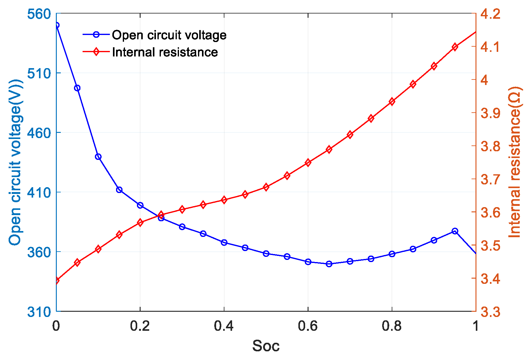
where U Bat , R D , U OCV , and U D are the battery dynamic parameters; they represent the polarization voltage, internal resistance, open circuit voltage, and polarization voltage, respectively. Those dynamic parameters are the function of the battery SOC S o c Bat , as shown in Figure 3.
Generally, the S o c Bat under dynamic current at time k can be expressed as follows:
S o c Bat , k = S o c Bat , 0 + 0 k I Bat , k d t / Q Bat
where Q Bat is the rated battery capacity.
Under short-term and low-frequency operation, UCs exhibit negligible leakage current and dielectric loss, so their energy flow and transient response can be accurately captured by an ideal model. Thus, the relationship between open circuit voltage V Uc and dynamic operating current I Uc at time k can be expressed as follows [38]:
V Uc , k = U Uc , k I Uc , k R Uc , k
where R Uc and U Uc denote the internal resistance and the ideal capacitor voltage, respectively.
In the charge and discharge process, the state of the charger of UC S o c Uc , k at time k can be expressed as follows:
S o c U c , k = S o c U c , k 1 k 1 k I U c , k d t / Q U c
where Q Uc is the rated UC capacity.

2.3. Model of Battery Lifetime Decay

The high power and high frequency of charging and discharging, along with the resulting current flow, inevitably lead to battery life degradation [2,39]. In this paper, we select the semi-empirical model, which combines theoretical analysis and experimental data to accurately describe the battery aging process [40]. The model can be expressed as follows:
Δ Q B a t , k = a exp ( χ + b c r a t e , k R T B a t ) ( A h ) z
A h = 0 k ( ε I B a t , k 2 + 1 ) I B a t , k d t
c r a t e , k = I B a t , k Q B a t
where A h is the amp-hour throughput of the battery, c rate is the battery operating rate, a , b , χ , ε and z are the pre-exponential parameters, R is the gas constant, and T Bat is the temperature in the core of the battery. The parameters used for the HESS power system, vehicle specifications, and the battery lifetime model are listed in Table 1.

3. Auto-Tuning Weight- and Constraint-Based MPC Method

Figure 4 depicts the proposed MPC-ATWC framework integrated with the VMD-LSTM predictor, which comprises three primary stages: forecasting vehicle velocity and road gradient using VMD-LSTM, auto-tuning of weights and constraints, and real-time power allocation optimization through MPC. Initially, the VMD-LSTM model accurately predicts power demand for the MPC. Subsequently, a hybrid method that combines rule-based and fuzzy logic-based strategies is utilized for auto-tuning weights and constraints. Specifically, the rule-based strategy regulates constraints during the recovery mode to isolate the battery from recharging and direct all recovery power to the UC, while the fuzzy logic-based strategy dynamically adjusts weights during the release mode to enhance UC utilization and overall system efficiency. Finally, MPC optimizes power allocation during each sample cycle. Then, the first optimal control variable is applied to the HESS in the EV, ensuring that power distribution is optimized based on the auto-tuned parameters.

3.1. The Power Demand Prediction with VMD-LSTM

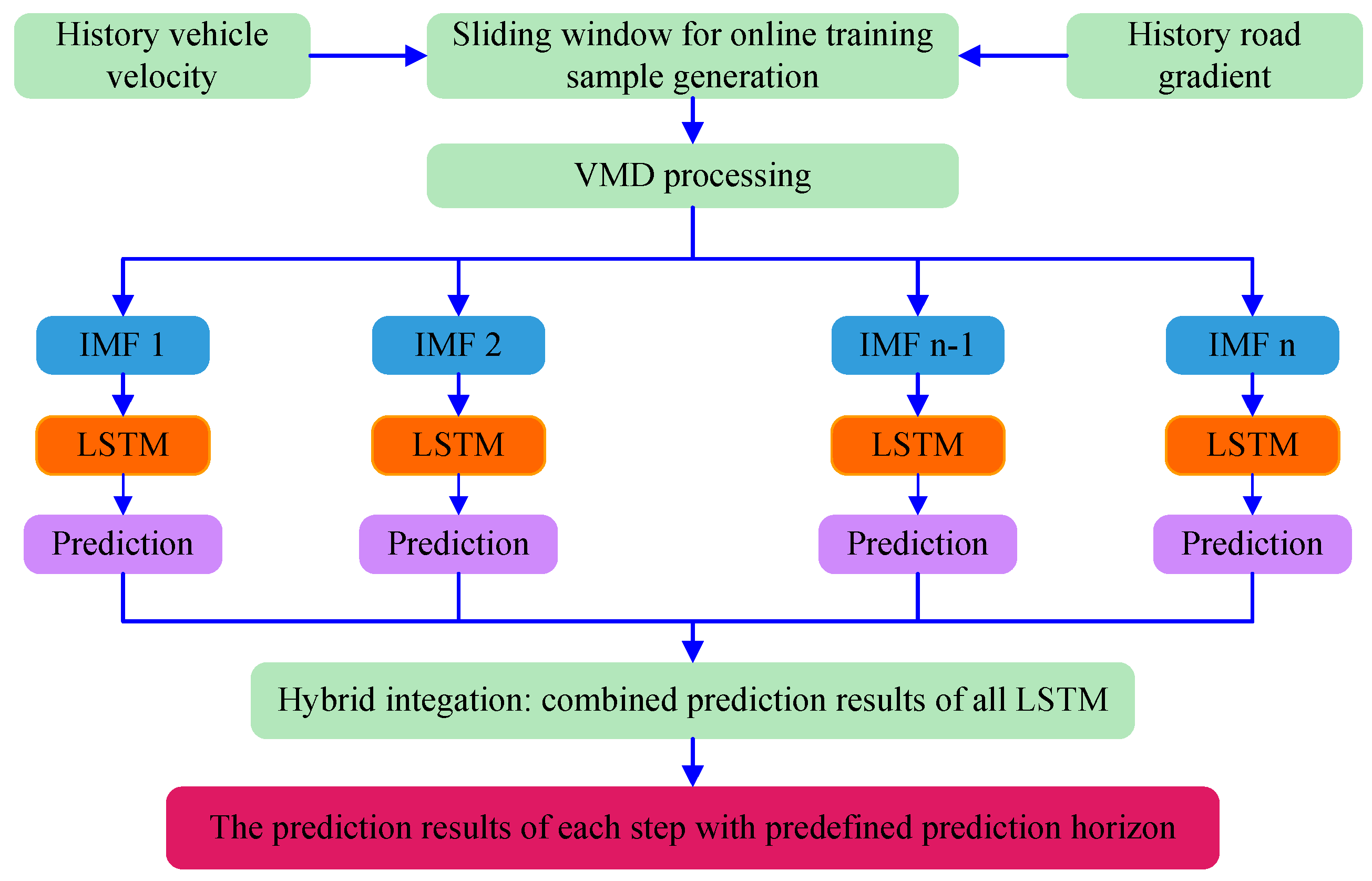
Although LSTM attains competent control performance, it remains limited in modeling strong nonlinearities and sustaining accuracy over long horizons. Recent VMD-based LSTM variants have overcome these weaknesses and shown exceptional predictive capacity, attracting widespread attention in nonlinear forecasting applications. Curiously, their benefits have not been examined for EMS of HESSs. We close this gap by introducing a VMD-LSTM framework that forecasts vehicle speed and road grade. The flowchart of the proposed VMD-LSTM prediction model is shown in Figure 5.
Under the proposed scheme, the online VMD-LSTM predictor operates exclusively on local history data as follows. First, sliding-window sampling is applied to produce training sequences whose length is set by the chosen forecast horizon. Each sequence is decomposed into intrinsic mode functions (IMFs) via online VMD. An individual LSTM is then trained and updated for every IMF; their outputs are summed to yield the current speed and slope forecasts, repeating this pipeline in a rolling manner and thus provide rolling power demand for EMS.

3.1.1. Model of the VMD

VMD is a non-recursive, adaptive technique that decomposes a signal into a set of intrinsic mode functions (IMFs), each characterized by a distinct center frequency and compact bandwidth, while guaranteeing that their sum perfectly reconstructs the original signal. Research shows that VMD markedly improves time series prediction accuracy. Assuming K intrinsic modes are extracted by VMD, the original velocity and road gradient H ( t ) can be expressed as follows:
H ( t ) = k = 1 K A k ( t ) cos ( φ k ( t ) )  
where A k ( t ) and φ k ( t ) are the envelope and phase at k model, respectively.
To obtain these modes, the decomposition process is formulated as a constrained variation problem, the function is as follows:
min u k ω k k = 1 K t ( δ ( t ) + j π t ) · u k ( t ) e j ω ¯ k t 2 2 s . t ω k ( t ) = φ k ( t ) t  
where u k are the shorthand notations of the mode, ω k are their center frequencies, and δ ( t ) is the Dirac delta.
To solve this constrained optimization, the problem is transformed into an unconstrained form by introducing an augmented Lagrangian that combines quadratic penalty terms with a Lagrange multiplier. The function is as follows:
L ( u k , ω k , λ ) = α k = 1 K t ( δ ( t ) + j π t ) · u k ( t ) e j ω ¯ k t 2 2 + H ( t ) k = 1 K u k ( t ) 2 2 + λ ( t ) , H ( t ) k = 1 K u k ( t )  
where α denotes the variance–regularization parameter and λ denotes the Lagrange multiplier.
Dragomiretskiy and Zosso solve this Lagrangian with the alternating direction method of multipliers (ADMM). The frequency-domain update u ^ k n + 1 ( ω ) of each mode and its center frequency ω ¯ k n + 1 are as follows:
u ^ k n + 1 ( ω ) = H ^ ( ω ) i < k u ^ i n + 1 ( ω ) + i > k u ^ i n ( ω ) + λ ^ n ( ω ) 2 1 + 2 α ( ω u ¯ k n ) 2 ω ¯ k n + 1 = 0 ω u ^ k n + 1 ( ω ) 2 d ω 0 u ^ k n + 1 ( ω ) 2 d ω  
where u ^ k n + 1 ( ω ) , H ^ ( ω ) , and λ ^ n ( ω ) are the Fourier transforms of u k ( t ) , H ( t ) , and λ ( t ) , respectively. After these quantities are updated, the Lagrange multiplier is adjusted via
λ ^ n + 1 ( ω ) = λ ^ n ( ω ) + τ ( H ^ ( ω ) k = 1 K u ^ k n + 1 ( ω ) )  
where τ controls the update rate.
Convergence is monitored through the criterion
k = 1 K u ^ k n + 1 ( ω ) u ^ k n ( ω ) 2 2 / u ^ k n ( ω ) 2 2 < ε  
where ε is the tolerance used to terminate operation. Once the modes have converged in the frequency domain, the corresponding time-domain IMFs are recovered by inverse Fourier transform.

3.1.2. Model of the LSTM

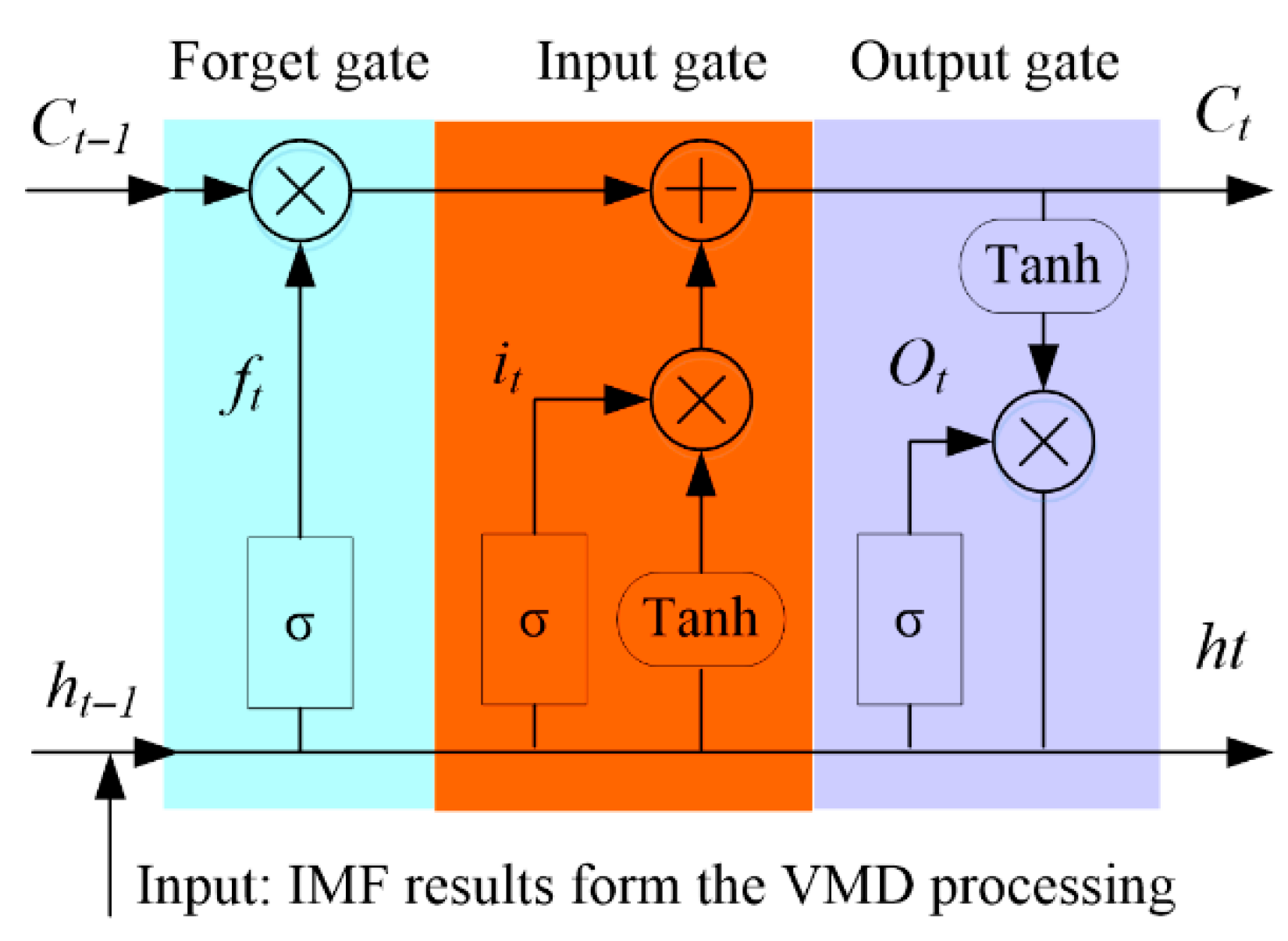
LSTM is an advanced recurrent architecture that mitigates gradient vanishing and exploding. Generally, it contains three gates: input, forget, and output. These gates use sigmoid activations and element-wise operations to capture long-range dependencies and generate reliable forecasts, as shown in Figure 6.
The input gate and forget gate jointly decide what to discard and what to retain at the current step. Their expressions are as follows:
f t = σ ( W f x x _ I M F , h t 1 + b f )
i t = σ ( W i x x _ I M F , h t 1 + b i )
where f t , W f , and b f denote the forget gate parameters, such as the weight matrices and bias vector; x x _ I M F denotes the input series of each IMF results. i t , W i , and b i are the input gate parameters which are constant with the forget gate.
Then, the processed information flows into the output gate, yielding the current output through activation functions and gate interactions. Its expression is as follows:
C t = f t C t 1 + i t t a n h ( W c x x _ I M F , h t 1 + b c )
C ¯ t = σ ( W c x x _ I M F , h t 1 + b c )
h t = σ ( W o x x _ I M F , h t 1 + b o ) t a n h ( f t C t 1 + i t C ¯ t )
where h t represents the output value in this step, C t represents the current state, and W c and b c represent the weights of the output gate and the bias vector.
Through the coordinated action of these gates, LSTM preserves essential information and discards the irrelevant. However, its performance is limited when handling non-stationary time series data. Thus, this paper proposes the VMD-LSTM method to improve prediction performance.

3.1.3. Actual Driving Cycle Test

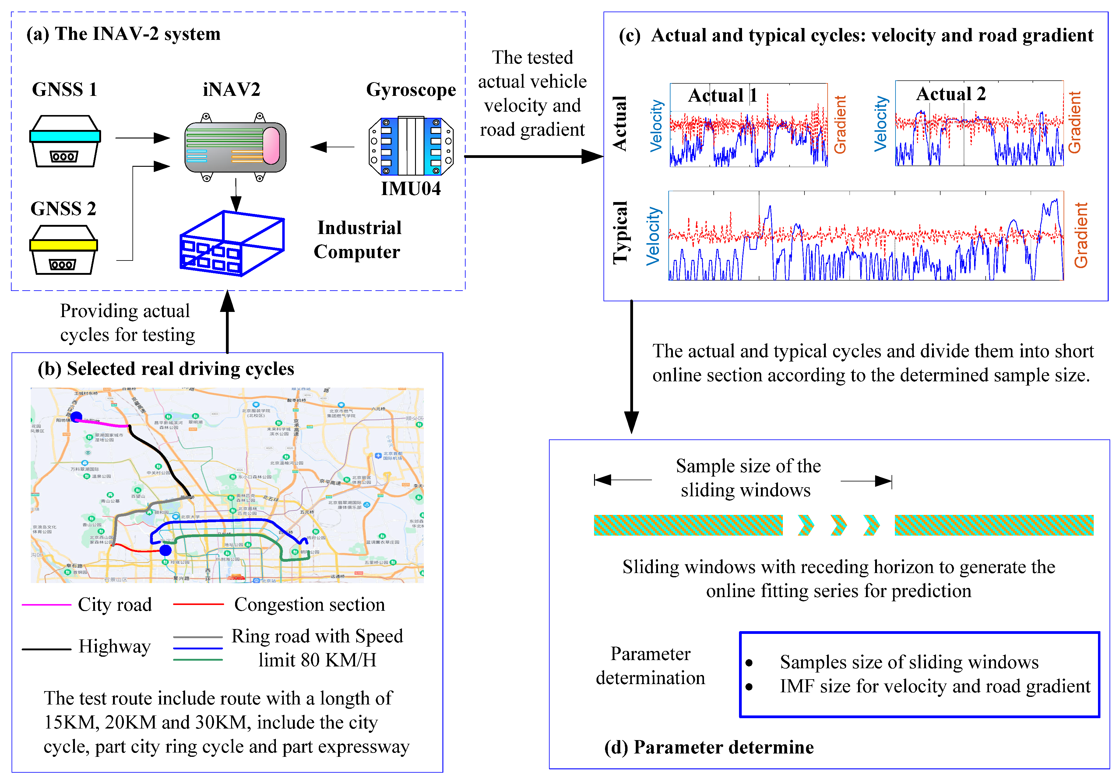
To validate the online predictor, we recorded real-world driving cycles in Beijing; a representative trace is shown in Figure 7. The route was deliberately composed of typical traffic environments, urban arterials, stop and go congestion, 80 km/h ring roads, and open highways, selected according to daily traffic flow statistics to ensure broad representativeness. Vehicle velocity was measured by a gyroscope, while dual external GNSS receivers logged high-accuracy longitudinal and vertical positions. Road gradient was then derived from these position data. All raw measurements were fused and down-streamed through an iNAV-2 inertial navigation system operating at 50 Hz. Beyond the collected data, typical cycles encompass broader probability distributions. By integrating these typical cycles of NEDC, UDDS, and WLTC, we enrich the validation scenarios and enable a deeper, more rigorous assessment of the proposed control strategies’ advancement. Finally, three combined driving cycles, actual-1, actual-2, and typical, are obtained. Subsequently, the combined cycles are divided into multiple shorter sections according to the determined sliding windows for parameter determination and prediction.

3.2. Formulation of the Adaptive MPC

3.2.1. The MPC Modeling

Leveraging its high real-time capability and proven effectiveness with nonlinear systems, we adopt MPC as the core of the EMS. In each control interval, the MPC solves the optimal power allocation based on the forecasted energy demand, the current system state, and the HESS boundary conditions. The discrete MPC formulation is given by the following:
x f ( k + 1 ) = A x f ( k ) + B Δ u ( k ) y f ( k ) = C x f ( k )
with
x f = U D , k S o c Bat , k S o c UC , k I Bat , k I UC , k T
y f = I Bat , k I UC , k T ,   Δ u ( k ) = Δ I Bat , k Δ I U C , k T
where Δ I Bat and Δ I S C are the current increases of the battery and UC, A , B and C are system incremental matrices under discrete state space, and A m , B m and C m are the coefficient matrices in the continuous time representation of the HESS, listed in Appendix A.
The primary objective of the proposed EMS is to ensure precise power demand tracking during vehicle operation while minimizing battery current fluctuations. Additionally, it is necessary to regulate the allocated power of the capacitor in real time. Based on these objectives, the multi-objective optimization problem in the k-th receding horizon can be formulated as follows:
J ( ξ ( k ) , Δ U ( k ) ) = i = 1 N p ( Y N p ( k + 1 | k ) I r e q ( k + i ) ) Q 2 + j = 1 N c 1 Δ U ( k + j ) R 2 + ρ ε 2
with
Y N p ( k + 1 | k ) = Ψ ξ ( k ) + Θ Δ U ( k )
subject to constraints
U D , min < U D , k < U D , max S o c Bat , min < S o c Bat , k < S o c Bat , max S o c UC , min < S o c UC , k < S o c UC , max I Bat , min < I Bat , k < I Bat , max I UC , min < I UC , k < I UC , max
where N c and N p are the control and prediction horizon, Y N p ( k + 1 | k ) is the output current of the HESS system, I r e q is the predicted power demand in the near future in current step, ε is the uncertain system variations, and Ψ , Θ , ξ ( k ) and Δ U ( k ) are the augmented matrix of the continuous system; the details are list in Appendix A. Q and R are the weight matrix corresponding to the power tracking and control variable.
The weights in the cost function quantify the relative importance of each control objective. By allowing these weights to vary in real time, the controller gains the flexibility to adapt its priorities to changing driving conditions. For the proposed EMS, the adaptive weight vector is expressed as follows:
Q = d i a g ( Q i , Q i , , Q i ) N p × N p R = d i a g ( R i , R i , , R i ) N c × N c
With the bus voltage held constant, the required current trajectory is derived directly from the predicted power demand; this single step converts the power split into explicit battery and UC currents, thereby accomplishing the HESS power allocation, which can be expressed as follows:
I r e q ( k + N p | k ) = P r e q ( k + N p | k ) / V b u s
where V b u s is the bus voltage.
Quadratic-programming (QP) solvers, which feature polynomial-time global optimality and explicit handling of hard constraints, have become the workhorse for real-time MPC and have been selected as the online solver for power optimization [41]; the function is as follows:
min f ( x ) = 1 2 Δ U ( k ) f T H Δ U ( k ) f + G ( k + 1 | k ) T Δ U ( k ) f S u b j e c t   t o ,   M u Δ U ( k ) f Γ ( k + 1 | k )
with
G ( k + 1 | k ) = Θ T Q ( Ψ ξ ( k ) I r e q ( k + i ) )
H = Θ T Q Θ + R
R i ( k ) = w Bat ( k ) 0 0 w UC ( k ) Q i ( k ) = w current ( k )
where w current ( k ) denotes the instantaneous power-tracking weight, and w Bat ( k ) and w UC ( k ) govern the battery-to-UC power-split ratio, respectively.

3.2.2. Auto-Tune Weights and Constraints with Rule-Based and Fuzzy Logic-Based Methods

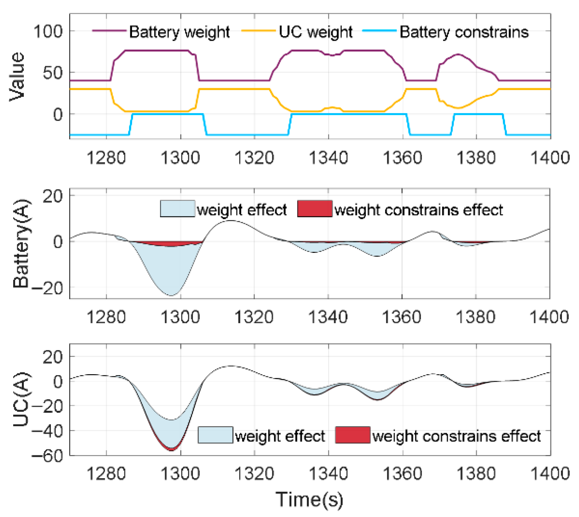
A supervisory hybrid method that synergizes rule-based logic with fuzzy inference is designed for the auto-tuning of the weights and constraints. At each sampling instant, the weight is adaptively re-tuned to regulate the battery and UC power ratio; in most conditions we lower the UC weight, thereby maximizing UC utilization. Simultaneously, the constraint is dynamically tightened to restrict the battery from being recharged and thus protect the battery from decaying. Figure 8 illustrates the resulting adaptive power allocation profile under simultaneous weight and constraint.
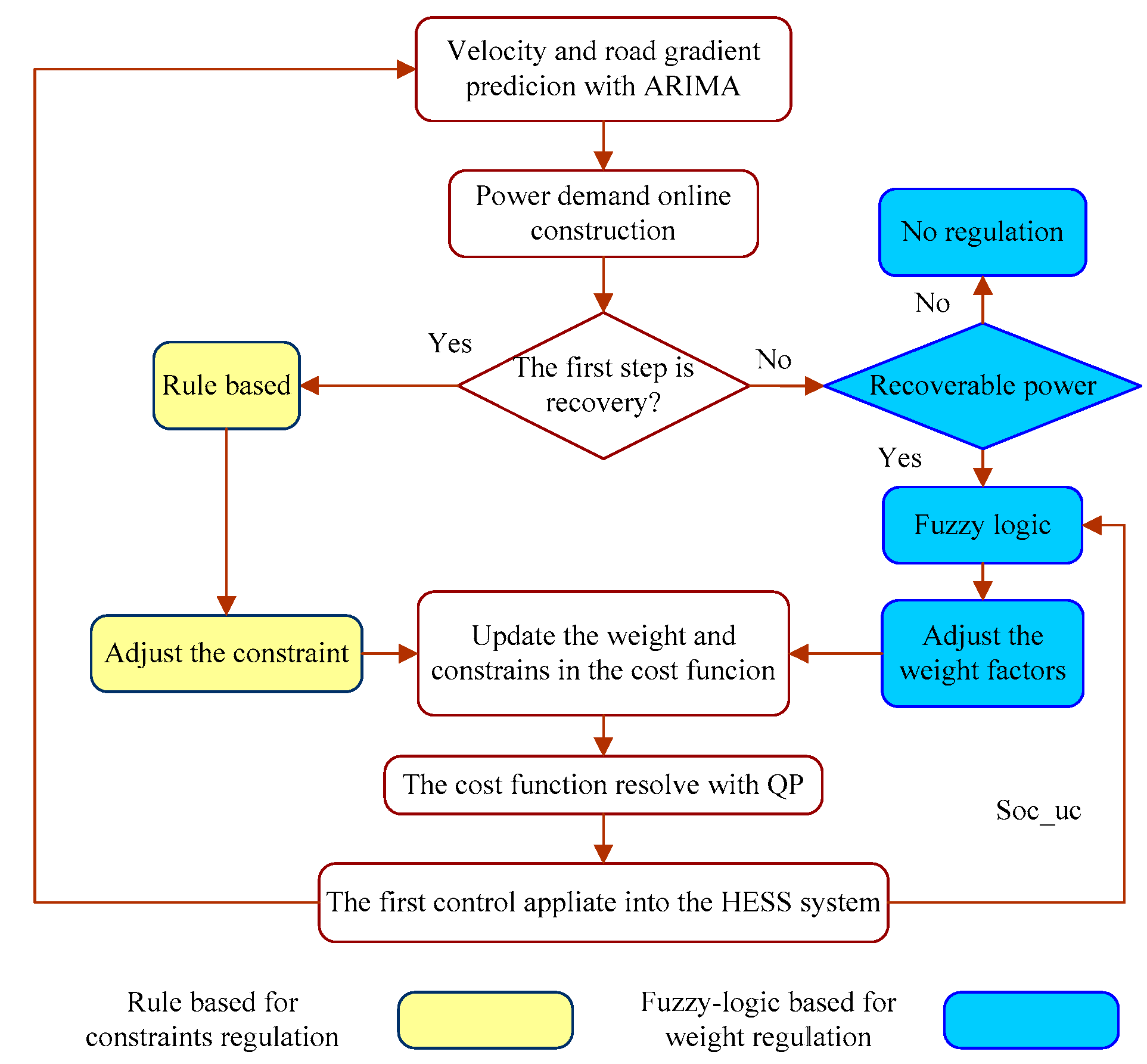
Figure 9 shows the flowchart of the rule-based and fuzzy logic regulation strategies. The rule-based approach is triggered in regenerative phases to cut down the recharge current flowing into the battery pack, whereas fuzzy logic regulates the weighting coefficients during propulsive phases to optimize UC discharge. Collectively, the dual mechanisms maximize UC energy throughput and minimize battery duty cycles, thereby extending battery calendar and cycle life.
For the rule-based regulator, the constraints are adjusted according to the first step in recovery conditions, isolating the battery from being recharged. The battery constraints are adjusted by the following:
I B a t , min = = 0 I p r e ( k + 1 | k ) 0 = I B a t , min I p r e ( k + 1 | k ) < 0
Meanwhile, the weights are regulated with a fuzzy logic regulator according to the power demand prediction in the near future. To prevent UC overuse, the weights are only adjusted when recoverable energy is predicted. The proportion of recoverable power to total projected energy K reco ( k ) predicted within the prediction horizon can be expressed as follows at each step k:
K reco ( k ) = ( 0.5 I abs ( k ) I sum ( k ) ) / I abs ( k )
with
I abs ( k ) = i = 1 N p I r e q ( k + i | k ) I sum ( k ) = i = 1 N p I r e q ( k + i | k )
Additionally, to facilitate convenient weight adjustment, the weights are adaptively tuned using an adjustment scale factor K reg , which is suggested as follows:
w Bat ( k ) = K reg ( k ) w Bat ( 0 ) w UC ( k ) =   [ 2 K reg ( k ) ] w UC ( 0 ) , K reg ( k )   [ 1 , 2 ]
where w Bat ( 0 ) and w UC ( 0 ) are the predefined weights. The main parameters of each component are illustrated in Table 2.
The fuzzy logic controller for weight regulation is depicted in Figure 10. The input variables are characterized by a Gaussian membership function and precise control is achieved using a first-order TS model. The K reco , S o c UC , and P abs are utilized as the input for the fuzzy logic controller to auto-tune the scale factor K reg . To ensure effective control, both the input and output variables are divided into five intervals. In particular, K reg ranges from 1 to 2 to meet the adjustment of weight.
According to the proposed methods, when K reg is zero, it indicates that no recoverable power is available. In this case, the weight remains at its fixed initial value, corresponding to a traditional EMS based on MPC with a fixed weight. However, when recoverable power is predicted during release conditions, the weight is adjusted dynamically. Specifically, as K reg increases, the UC weight is reduced while the battery weight is increased. This adjustment prioritizes the UC, thereby enhancing its utilization. The degree of weight adjustment is determined based on the predicted recoverable power ratio K reco , the total power demand. Overall, the auto-tuning of weights and constraints significantly enhances UC utilization and prolongs battery life by dynamically adapting to varying power conditions.

4. Results and Discussion

To evaluate the efficacy of the proposed MPC-ATWC for HESS energy management, extensive simulations were conducted on a computer equipped with an Intel(R) i7-9800 CPU, which has a maximum operating frequency of 4.20 GHz.

4.1. The VMD-LSTM Prediction Performance

First, the prediction performance of the proposed VMD-LSTM is conducted. The R-Square ( R 2 ) results are added to the comprehensive evaluation of the prediction performance. In general, the RMSE and ARMSE indicate the prediction error, and R 2 provides insights into the effectiveness of the model fit. The R 2 functions are as follows:
R 2 = 1 k = 1 N p Y p k Y d k 2 / k = 1 N p Y d k 1 n k = 1 N p Y d k 2
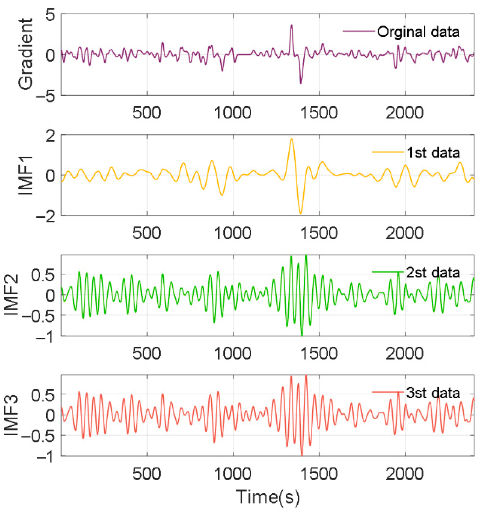
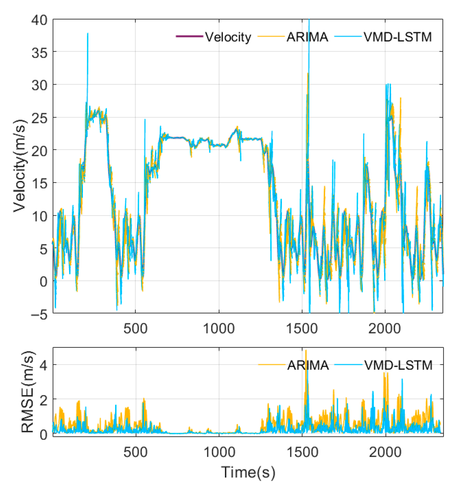
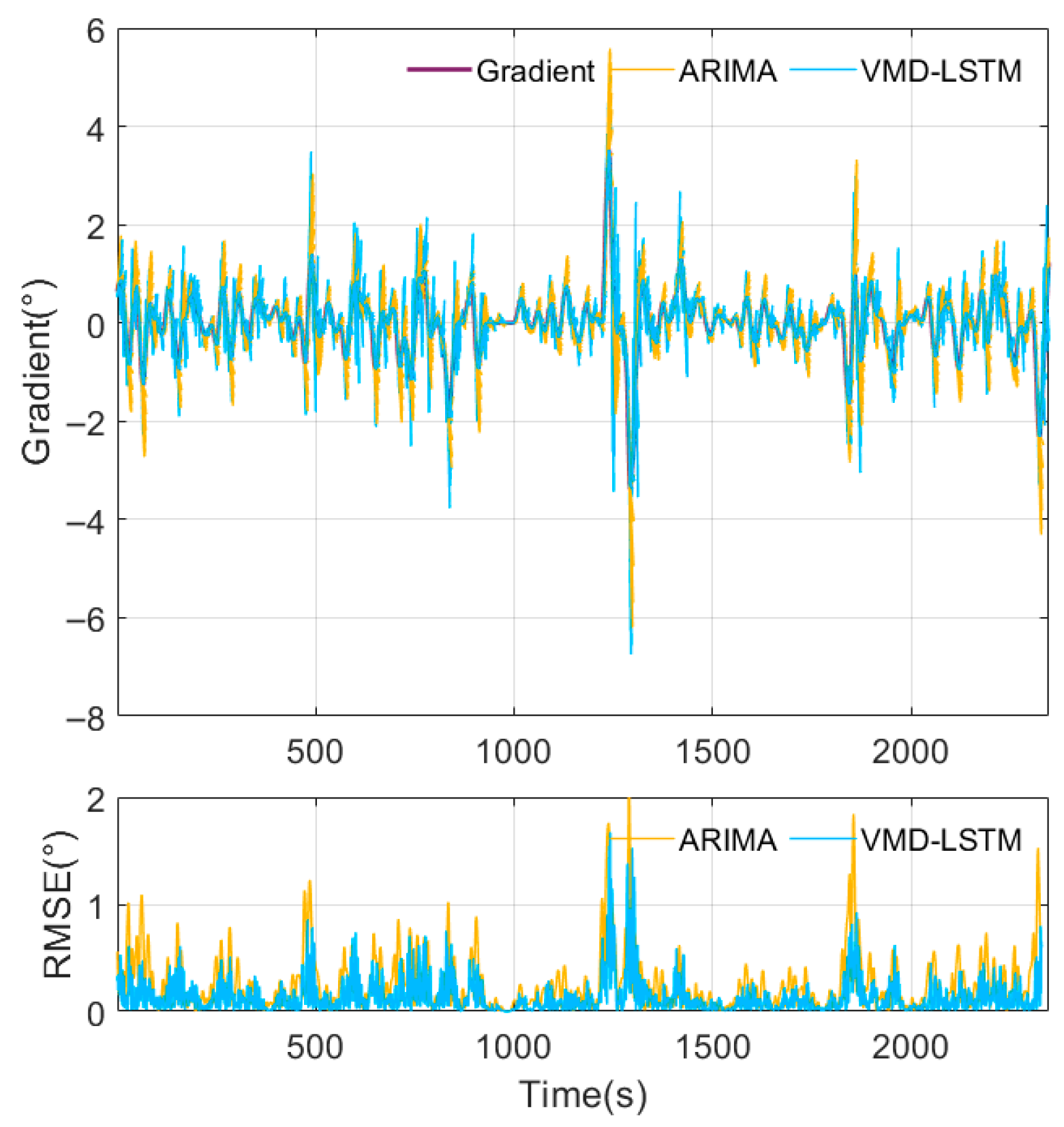
Figure 11 and Figure 12 evaluates the IMF results of the velocity and road gradient and prediction results from 10 s ahead with VMD-LSTM under cycle-2. As illustrated, VMD decomposes the speed and slope signals into linear and nonlinear components via third-order decomposition. As the IMF results show, an order of 3 cleanly separates the velocity modes while keeping them distinct, while the road gradient components begin to overlap beyond 2 modes. The raising order slows the online compute, so we fix the velocity decomposition at 3 and the road gradient decomposition at 2. The compared prediction results with ARIMA are plotted in Figure 13 and Figure 14. According to the compared results, with VMD preprocessing, the VMD-LSTM model accurately forecasts future vehicle velocity and captures nonlinear dynamics, sharply reducing errors in sections where velocity and road gradient vary sharply.
To confirm its broad applicability and accuracy, the VMD-LSTM algorithm was benchmarked across multiple prediction horizons against leading time series models, such as RBF-NN, ARIMA, and LSTM [42]. The results, presented in Table 3, show that VMD-LSTM achieves satisfactory prediction accuracy, comparable to these advanced methods. Although its runtime is marginally longer than that of ARIMA, the increase remains acceptable, achieving an effective trade-off between precision and efficiency. Consequently, VMD-LSTM is well-suited to refining power split strategies and enabling reliable, real-time updates to weights and constraints.

4.2. The Power-Tracking Performance of the Proposed Strategy

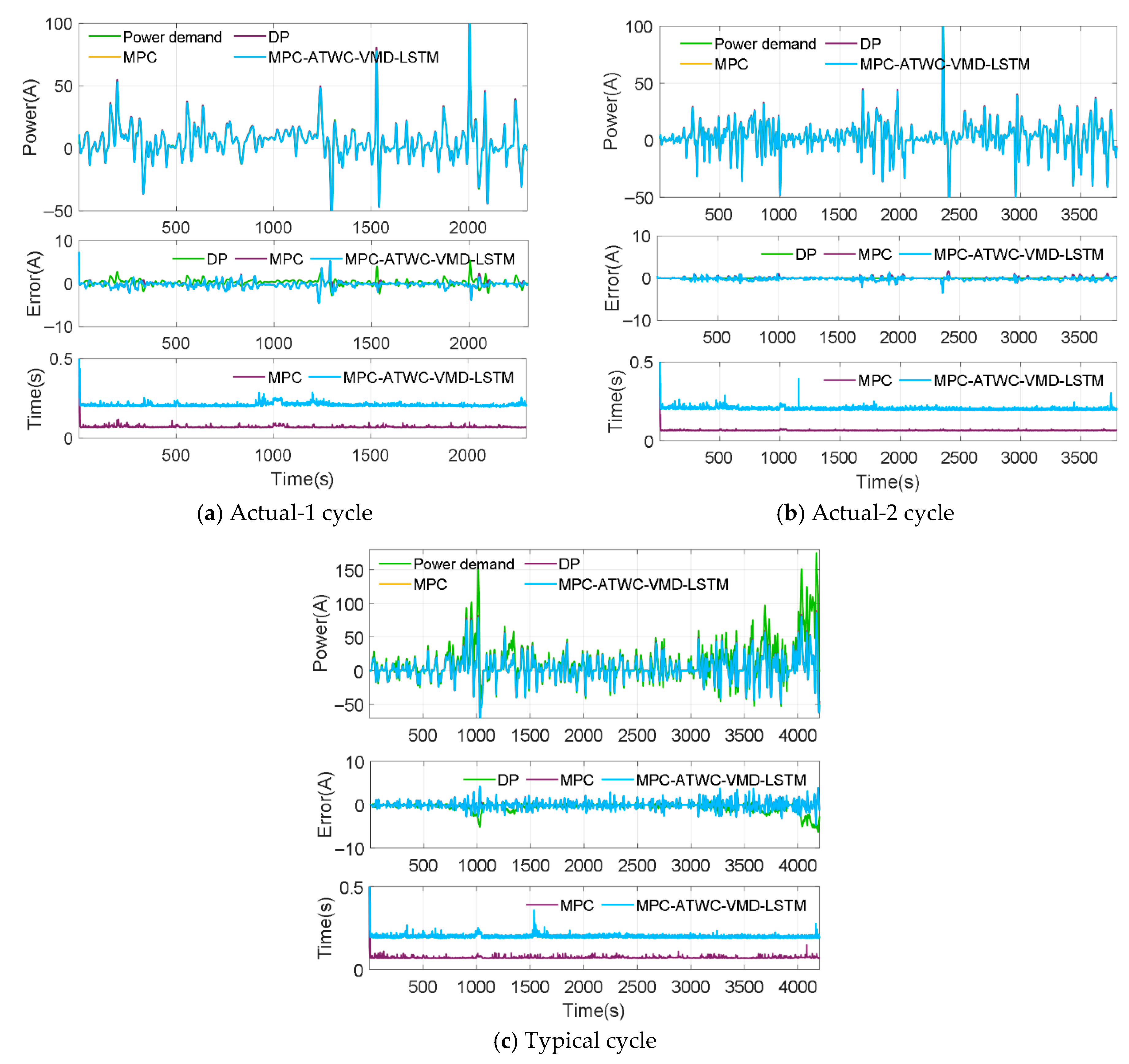
Power-tracking capability is the primary criterion that every EMS must satisfy. To quantify how our adaptive-weight tuning and predictive algorithm influence this capability, we compared the proposed MPC-ATWC with VMD-LSTM (MPC-ATWC-VMD-LSTM) against both traditional MPC and DP under three representative driving cycles.
The results, shown in Figure 15, demonstrate that the MPC-ATWC-VMD-LSTM tracks the power demand as closely as the benchmark MPC and DP. Even during aggressive load transients, the controller maintains excellent tracking fidelity. The largest current deviation is about 7 A, which corresponds to 5% of the reference at that instant. This confirms that the VMD-LSTM module accurately anticipates fast load changes, while the auto-tuning weights and constraints ensure the tracking error remains tightly bounded. Although the proposed algorithm increases the single-step computation time from 0.1 s (traditional MPC) to 0.3 s, the additional latency is modest and the resulting energy regulation remains smooth and responsive, which is acceptable for real-time implementation.

4.3. Effect of Weight and Constraints on Power Allocation

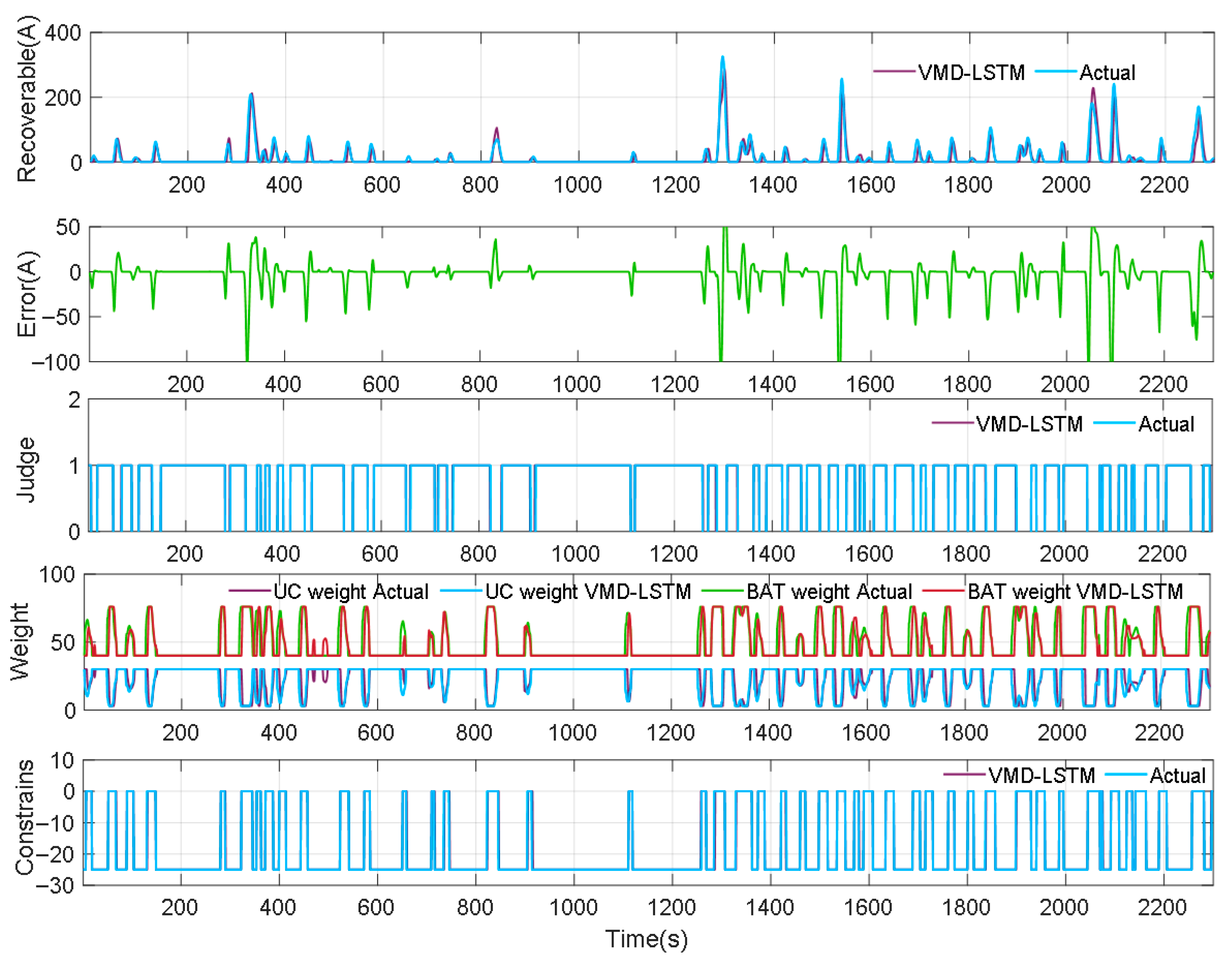
Accurate auto-tuning of weights and constraints is crucial for optimizing power allocation. Figure 16 illustrates the predicted recoverable power, prediction error, initial judgment results, and auto-tuning weights and constraints from top to bottom. The results show that the predicted recoverable power, based on the VMD-LSTM model, closely matches the actual power, with only occasional deviations during certain periods. This indicates that the auto-tuning approach guided by VMD-LSTM achieves high accuracy. In release mode, the battery weight and UC are dynamically adjusted according to the predicted recoverable power. During recovery conditions, the battery constraints are promptly adjusted to isolate the current flowing into the battery, thereby achieving a pure UC model.
Figure 17 contrasts the proposed adaptive EMS against an MPC that employs fixed parameters. The adaptive EMS continuously recalibrates the power split in real time, boosting UC utilization while strictly bounding battery C-rates. During recuperation, the battery is electrically decoupled: the entire braking energy is channeled to the UC through automatically tightened constraints. When the preview horizon anticipates recoverable power, the self-tuning weights prompt the UC to shoulder the extra load during acceleration. In contrast, the fixed-weight strategy rigidly apportions power, forcing the battery to supply a constant fraction regardless of operating conditions.
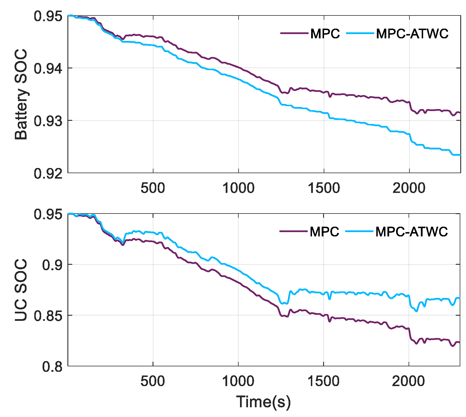
Figure 18 presents a detailed adaptive power allocation process during the 315 s to 345 s period. At the initial step of 317 s in the release cycle, weight tuning is initiated due to minimal predicted recoverable power, while constraints remain at −25. When the time reaches 320 s, sufficient recoverable current is predicted from 324 s to 327 s, prompting an increase in weight. Consequently, the battery’s power is constrained (green area), while the UC is encouraged to provide nearly all the required power (cyan area), thereby improving UC utilization. At 323 s, the first step transitions to recovery mode, and the constraint is adjusted to 0, isolating the battery from being recharged until 345 s. During this period, the recoverable power is entirely recovered by the UC, achieving a pure UC model. With auto-tuning weights and constraints, the UC achieves higher utilization and a higher SOC compared to MPC, as demonstrated in Figure 19. It should be noted that the battery SOC is lower than in conventional methods due to the isolation of the battery during power recovery.
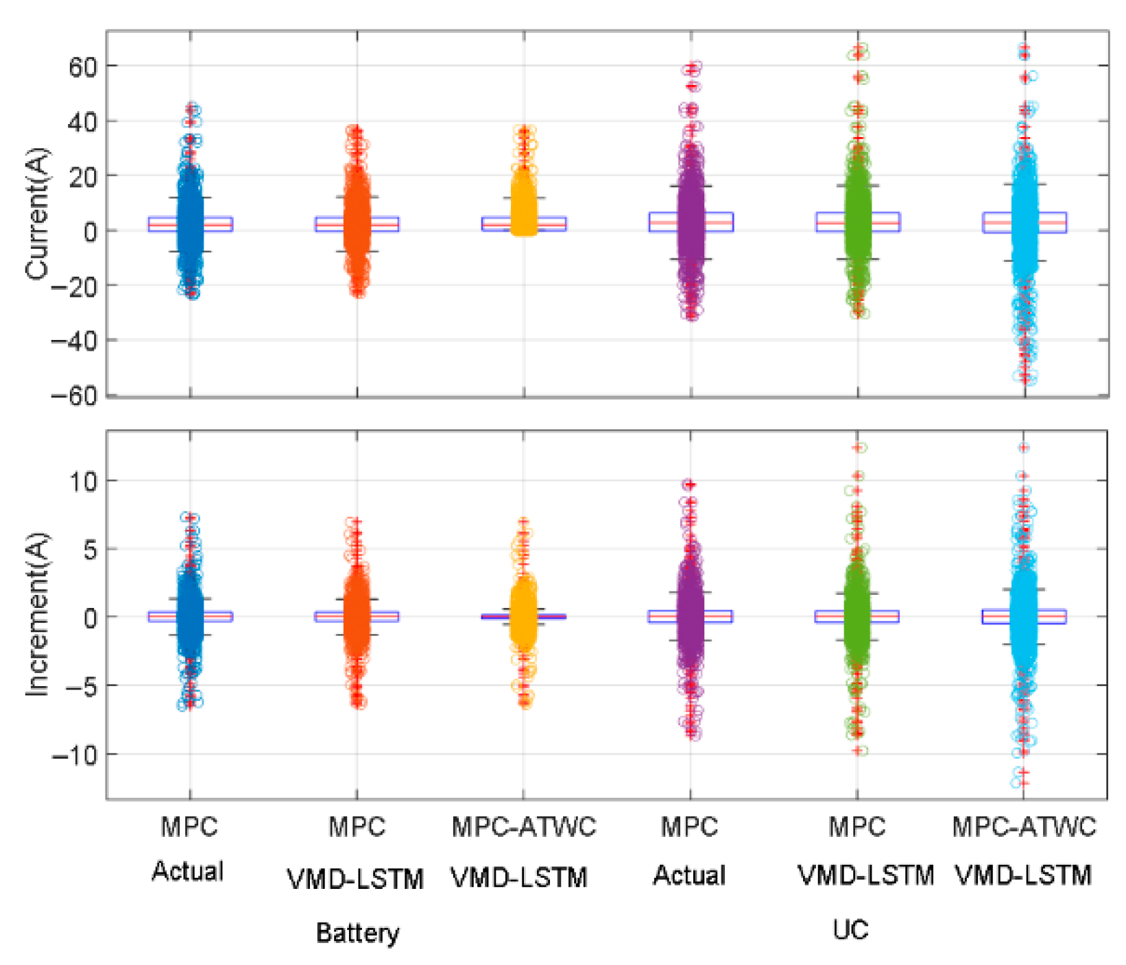
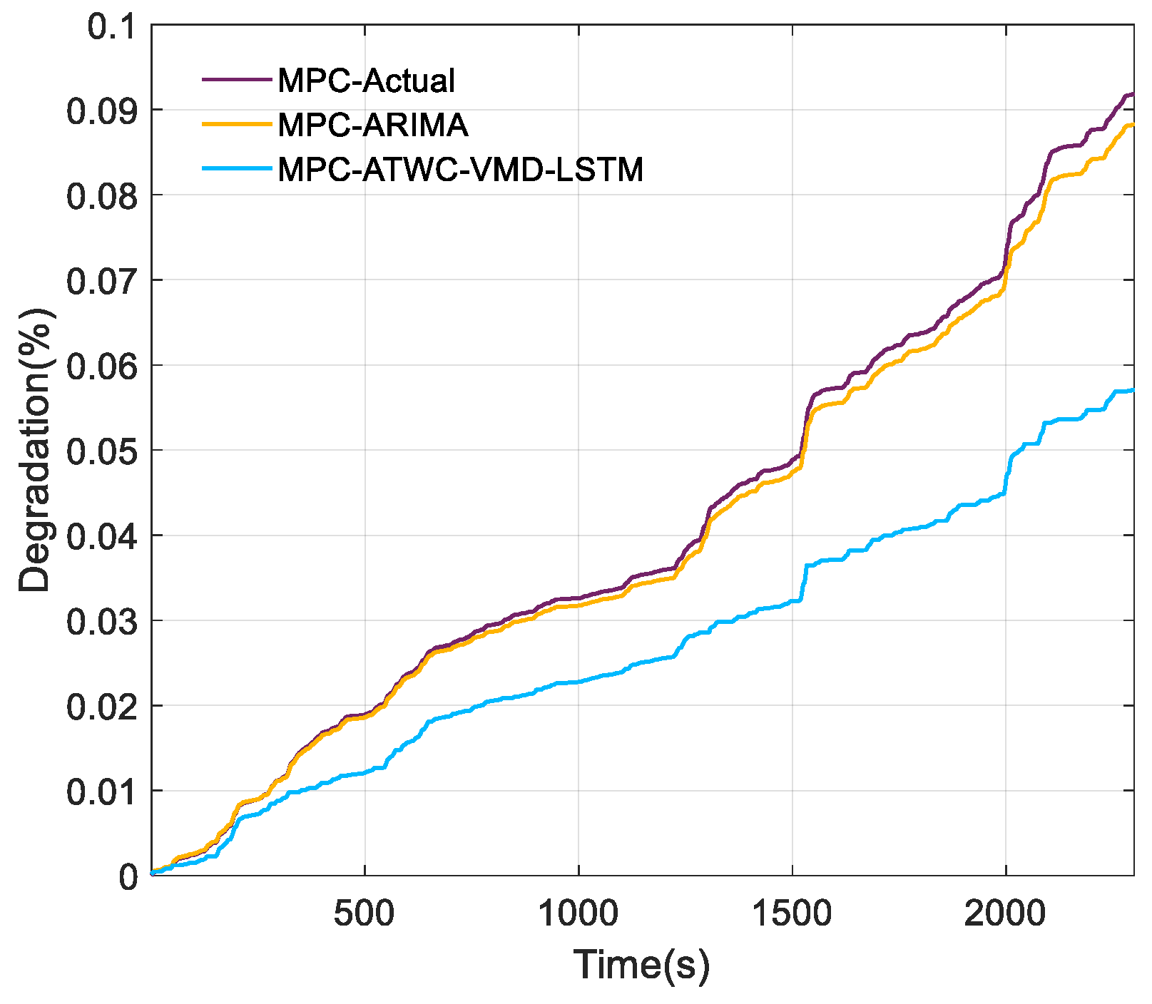
Battery degradation is governed by the dynamic profile of the current and its rate of change. Figure 20 and Figure 21 reveal that the proposed real-time tuning weights and constraints keep the battery current virtually flat and block any regeneration into the pack. Traditional MPC, by comparison, subjects the battery to pronounced current fluctuation and heavier-duty cycles, hastening wear. Consequently, the adaptive EMS prolongs battery life by stabilizing the current trace and lowering battery utilization, as summarized in Figure 22.

4.4. Overall Evaluation

Table 4 quantifies the performance of the proposed MPC-ATWC against the traditional DP baseline (set to 100%). The metrics include battery/UC utilization, ERC-induced battery aging, and computation time. Across all cycles, UC usage is markedly improved at only a modest rise in runtime. When the controller is paired with the VMD-LSTM predictor, UC utilization and battery longevity both surpass those obtained with the LSTM version, emphasizing the value of accurate power demand forecasts. Overall, the adaptive weigh and constraint tuning boosts UC utilization by 10.98% and extends battery life by 19.75%. Although validated on the HESS EMS, the approach can be seamlessly transferred to other hybridized EV architectures for real-time, adaptive energy distribution.

5. Conclusions

Maximizing UC utilization while mitigating battery stress is essential for improving both the efficiency and longevity of HESS. This paper proposes an MPC framework featuring auto-tuning weights and constraints, thereby simultaneously achieving both objectives. A VMD-LSTM predictor delivers accurate, nonlinear power demand forecasts to guide the MPC optimizer and enable online adjustment of weights and constraints. The resulting power allocation problem is solved efficiently via QP. Furthermore, a novel rule-based and fuzzy logic strategy is introduced for efficient auto-tuning of weights and constraints. This approach not only maximizes UC utilization but also smoothly isolates the battery from direct recharge. Experimental results show that auto-tuning weights and constraints increases UC utilization by 10.98% and extends battery life by 19.75%, underscoring the practical potential of the proposed strategy for EVs.

Author Contributions

Conceptualization, B.M.; methodology, B.M. and Y.Y.; software, Y.Y.; validation B.M. and Y.Y.; formal analysis, B.M. and P.-H.L.; writing—original draft preparation, B.M. and Y.Y.; writing—review and editing, B.M. and Y.Y. All authors have read and agreed to the published version of the manuscript.

Funding

This work is supported by the National Natural Science Foundation of Beijing [3212005] and the National Natural Science Foundation of China [52302425, 51608040].

Institutional Review Board Statement

Not applicable.

Informed Consent Statement

Not applicable.

Data Availability Statement

The original contributions presented in the study are included in the article, further inquiries can be directed to the corresponding author.

Conflicts of Interest

Author Yi Yang was employed by the company China Automotive Engineering Research Institute Co., Ltd. and Guangdong Automotive Test Center Co., Ltd. The remaining authors declare that the research was conducted in the absence of any commercial or financial relationships that could be construed as a potential conflict of interest.

Appendix A

A = A m B m 0 I ,   B = B m I ,   C = C m 1 1
A m = exp ( Δ t / τ Bat , k 1 ) 0 0 0 1 0 0 0 1 ,   B m = 1 exp ( Δ t / τ Bat , k 1 ) 0 1 / Q Bat 0 0 1 / Q UC
C m = 0 0 0 ,   ξ ( k ) = x ( k ) u ( k 1 ) ,   Δ U ( k ) = Δ u ( k ) Δ u ( k + 1 ) Δ u ( k + N c 1 )
Y N p ( k + 1 | k ) = y f ( k + 1 | k ) y f ( k + 2 | k ) y f ( k + N p | k ) ,   Ψ = C A C A 2 C A N p
Θ = C B 0 0 0 C A B C B 0 0 C A N p 1 B C A N p 2 B C A N p N e 1 B

References

  1. Gao, D.; Luo, Z.; Liu, C.; Fan, S. A Survey of Hybrid Energy Devices Based on Supercapacitors. Green Energy Environ. 2023, 8, 972–988. [Google Scholar] [CrossRef]
  2. Li, F.; Gao, Y.; Wu, Y.; Xia, Y.; Wang, C.; Hu, J.; Huang, Z. Incentive Learning-Based Energy Management for Hybrid Energy Storage System in Electric Vehicles. Energy Convers. Manag. 2023, 293, 117480. [Google Scholar] [CrossRef]
  3. Luo, Y.; Fang, S.; Niu, T.; Fan, A.; Liao, R. Hierarchical Power Management of Shipboard Hybrid Energy Storage System Under Multiple Pulse Loads. IEEE Trans. Ind. Appl. 2024, 60, 1380–1395. [Google Scholar] [CrossRef]
  4. Ma, B.; Guo, X.; Li, P. Adaptive Energy Management Strategy Based on a Model Predictive Control with Real-Time Tuning Weight for Hybrid Energy Storage System. Energy 2023, 283, 129128. [Google Scholar] [CrossRef]
  5. Zhu, Y.; Li, X.; Liu, Q.; Li, S.; Xu, Y. Review Article: A Comprehensive Review of Energy Management Strategies for Hybrid Electric Vehicles. Mech. Sci. 2022, 13, 147–188. [Google Scholar] [CrossRef]
  6. Zhang, S.; Xiong, R. Adaptive Energy Management of a Plug-in Hybrid Electric Vehicle Based on Driving Pattern Recognition and Dynamic Programming. Appl. Energy 2015, 155, 68–78. [Google Scholar] [CrossRef]
  7. Wang, H.; He, H.; Li, J.; Bai, Y.; Chang, Y.; Yan, B. Adaptive MPC Based Real-Time Energy Management Strategy of the Electric Sanitation Vehicles. Appl. Sci. 2021, 11, 498. [Google Scholar] [CrossRef]
  8. Zhu, T.; Wills, R.G.A.; Lot, R.; Ruan, H.; Jiang, Z. Adaptive Energy Management of a Battery-Supercapacitor Energy Storage System for Electric Vehicles Based on Flexible Perception and Neural Network Fitting. Appl. Energy 2021, 292, 116932. [Google Scholar] [CrossRef]
  9. Yang, N.; Han, L.; Liu, R.; Wei, Z.; Liu, H.; Xiang, C. Multiobjective Intelligent Energy Management for Hybrid Electric Vehicles Based on Multiagent Reinforcement Learning. IEEE Trans. Transp. Electrif. 2023, 9, 4294–4305. [Google Scholar] [CrossRef]
  10. Asensio, E.M.; Magallán, G.A.; Pérez, L.; De Angelo, C.H. Short-Term Power Demand Prediction for Energy Management of an Electric Vehicle Based on Batteries and Ultracapacitors. Energy 2022, 247, 123430. [Google Scholar] [CrossRef]
  11. Zheng, C.; Li, W.; Liang, Q. An Energy Management Strategy of Hybrid Energy Storage Systems for Electric Vehicle Applications. IEEE Trans. Sustain. Energy 2018, 9, 1880–1888. [Google Scholar] [CrossRef]
  12. Nie, Z.; Song, H.; Lian, Y.; Shi, Z. BiLSTM-ATTENTION-CNN Predictive Energy Management Based on ISSA Optimization for Intelligent Fuel Cell Hybrid Vehicle Platoon. Energy 2025, 324, 135860. [Google Scholar] [CrossRef]
  13. Lin, Z.; Chen, Z.; Liu, J.; Wu, Q. Coordinated Mechanical Loads and Power Optimization of Wind Energy Conversion Systems with Variable-Weight Model Predictive Control Strategy. Appl. Energy 2019, 236, 307–317. [Google Scholar] [CrossRef]
  14. Zhang, Y.; Chen, Z.; Li, G.; Liu, Y.; Huang, Y.; Cunningham, G.; Early, J. Integrated Velocity Prediction Method and Application in Vehicle-Environment Cooperative Control Based on Internet of Vehicles. IEEE Trans. Veh. Technol. 2022, 71, 2639–2654. [Google Scholar] [CrossRef]
  15. Ewusie, J.E.; Soobiah, C.; Blondal, E.; Beyene, J.; Thabane, L.; Hamid, J.S. Methods, Applications and Challenges in the Analysis of Interrupted Time Series Data: A Scoping Review. J. Multidiscip. Healthc. 2020, 13, 411–423. [Google Scholar] [CrossRef]
  16. Quan, S.; Wang, Y.-X.; Xiao, X.; He, H.; Sun, F. Real-Time Energy Management for Fuel Cell Electric Vehicle Using Speed Prediction-Based Model Predictive Control Considering Performance Degradation. Appl. Energy 2021, 304, 117845. [Google Scholar] [CrossRef]
  17. Guo, L.; Liu, H.; Han, L.; Yang, N.; Liu, R.; Xiang, C. Predictive Energy Management Strategy of Dual-Mode Hybrid Electric Vehicles Combining Dynamic Coordination Control and Simultaneous Power Distribution. Energy 2023, 263, 125598. [Google Scholar] [CrossRef]
  18. Guo, J.; He, H.; Sun, C. ARIMA-Based Road Gradient and Vehicle Velocity Prediction for Hybrid Electric Vehicle Energy Management. IEEE Trans. Veh. Technol. 2019, 68, 5309–5320. [Google Scholar] [CrossRef]
  19. Wang, W.; Ma, B.; Guo, X.; Chen, Y.; Xu, Y. A Hybrid ARIMA-LSTM Model for Short-Term Vehicle Speed Prediction. Energies 2024, 17, 3736. [Google Scholar] [CrossRef]
  20. Chen, H.; Lu, T.; Huang, J.; He, X.; Yu, K.; Sun, X.; Ma, X.; Huang, Z. An Improved VMD-LSTM Model for Time-Varying GNSS Time Series Prediction with Temporally Correlated Noise. Remote Sens. 2023, 15, 3694. [Google Scholar] [CrossRef]
  21. Ji, Q.; Han, L.; Jiang, L.; Zhang, Y.; Xie, M.; Liu, Y. Short-Term Prediction of the Significant Wave Height and Average Wave Period Based on the Variational Mode Decomposition–Temporal Convolutional Network–Long Short-Term Memory (VMD–TCN–LSTM) Algorithm. Ocean Sci. 2023, 19, 1561–1578. [Google Scholar] [CrossRef]
  22. Ding, T.; Wu, D.; Shen, L.; Liu, Q.; Zhang, X.; Li, Y. Prediction of Significant Wave Height Using a VMD-LSTM-Rolling Model in the South Sea of China. Front. Mar. Sci. 2024, 11, 1382248. [Google Scholar] [CrossRef]
  23. Ramasamy, V.; Kannan, R.; Muralidharan, G.; Sidharthan, R.K.; Veerasamy, G.; Venkatesh, S.; Amirtharajan, R. Comprehensive Review on Advanced Process Control of Cement Kiln Process with the Focus on MPC Tuning Strategies. J. Process Control 2023, 121, 85–102. [Google Scholar] [CrossRef]
  24. Gomozov, O.; Trovao, J.P.F.; Kestelyn, X.; Dubois, M.R. Adaptive Energy Management System Based on a Real-Time Model Predictive Control With Nonuniform Sampling Time for Multiple Energy Storage Electric Vehicle. IEEE Trans. Veh. Technol. 2017, 66, 5520–5530. [Google Scholar] [CrossRef]
  25. Sun, J.; Li, Z.; Li, J.; Wu, G.; Xia, Y. Hybrid Power System with Adaptive Adjustment of Weight Coefficients Multi-Objective Model Predictive Control. Int. J. Electr. Power Energy Syst. 2023, 153, 109296. [Google Scholar] [CrossRef]
  26. Zhan, S.; Chen, Y.; Ringwood, J.V. Terminal Weight and Constraint Design for Wave Energy Converter Economic Model Predictive Control Problems. Int. J. Robust Nonlinear Control 2023, 35, 2694–2716. [Google Scholar] [CrossRef]
  27. Bakibillah, A.S.M.; Kamal, M.A.S.; Tan, C.P.; Hayakawa, T.; Imura, J. Fuzzy-Tuned Model Predictive Control for Dynamic Eco-Driving on Hilly Roads. Appl. Soft Comput. 2021, 99, 106875. [Google Scholar] [CrossRef]
  28. Zhao, R.C.; Wong, P.K.; Xie, Z.C.; Zhao, J. Real-Time Weighted Multi-Objective Model Predictive Controller for Adaptive Cruise Control Systems. Int. J. Automot. Technol. 2017, 18, 279–292. [Google Scholar] [CrossRef]
  29. Liu, H.; Chen, G.; Li, D.; Wang, J.; Zhou, J. Energy Active Adjustment and Bidirectional Transfer Management Strategy of the Electro-Hydrostatic Hydraulic Hybrid Powertrain for Battery Bus. Energy 2021, 230, 120794. [Google Scholar] [CrossRef]
  30. Yang, C.; Sun, T.; Wang, W.; Li, Y.; Zhang, Y.; Zha, M. Regenerative Braking System Development and Perspectives for Electric Vehicles: An Overview. Renew. Sustain. Energy Rev. 2024, 198, 114389. [Google Scholar] [CrossRef]
  31. Lü, X.; Li, S.; He, X.; Xie, C.; He, S.; Xu, Y.; Fang, J.; Zhang, M.; Yang, X. Hybrid Electric Vehicles: A Review of Energy Management Strategies Based on Model Predictive Control. J. Energy Storage 2022, 56, 106112. [Google Scholar] [CrossRef]
  32. Ju, F.; Murgovski, N.; Zhuang, W.; Wang, Q.; Wang, L. Predictive Cruise Controller for Electric Vehicle to Save Energy and Extend Battery Lifetime. IEEE Trans. Veh. Technol. 2023, 72, 469–482. [Google Scholar] [CrossRef]
  33. Yan, M.; Li, G.; Li, M.; He, H.; Xu, H.; Liu, H. Hierarchical Predictive Energy Management of Fuel Cell Buses with Launch Control Integrating Traffic Information. Energy Convers. Manag. 2022, 256, 115397. [Google Scholar] [CrossRef]
  34. Wu, G.; Wang, C.; Zhao, W.; Meng, Q. Integrated Energy Management of Hybrid Power Supply Based on Short-Term Speed Prediction. Energy 2023, 262, 125620. [Google Scholar] [CrossRef]
  35. Zhou, L.; Yang, D.; Zeng, X.; Zhang, X.; Song, D. Multi-Objective Real-Time Energy Management for Series–Parallel Hybrid Electric Vehicles Considering Battery Life. Energy Convers. Manag. 2023, 290, 117234. [Google Scholar] [CrossRef]
  36. Uddin, M.; Mekhilef, S.; Rivera, M.; Rodriguez, J. Imposed Weighting Factor Optimization Method for Torque Ripple Reduction of IM Fed by Indirect Matrix Converter with Predictive Control Algorithm. J. Electr. Eng. Technol. 2015, 10, 227–242. [Google Scholar] [CrossRef]
  37. Zhang, F.; Wang, L.; Coskun, S.; Pang, H.; Cui, Y.; Xi, J. Energy Management Strategies for Hybrid Electric Vehicles: Review, Classification, Comparison, and Outlook. Energies 2020, 13, 3352. [Google Scholar] [CrossRef]
  38. Chen, H.; Xiong, R.; Lin, C.; Shen, W. Model Predictive Control Based Real-Time Energy Management for a Hybrid Energy Storage System. CSEE J. Power Energy Syst. 2020, 7, 862–874. [Google Scholar] [CrossRef]
  39. Zhou, Y.; Ravey, A.; Péra, M.-C. Real-Time Cost-Minimization Power-Allocating Strategy via Model Predictive Control for Fuel Cell Hybrid Electric Vehicles. Energy Convers. Manag. 2021, 229, 113721. [Google Scholar] [CrossRef]
  40. Feng, Y.; Dong, Z. Optimal Energy Management with Balanced Fuel Economy and Battery Life for Large Hybrid Electric Mining Truck. J. Power Sources 2020, 454, 227948. [Google Scholar] [CrossRef]
  41. Jia, C.; Cui, J.; Qiao, W.; Qu, L. Real-Time Model Predictive Control for Battery-Supercapacitor Hybrid Energy Storage Systems Using Linear Parameter-Varying Models. IEEE J. Emerg. Sel. Top. Power Electron. 2023, 11, 251–263. [Google Scholar] [CrossRef]
  42. Hou, J.; Yao, D.; Wu, F.; Shen, J.; Chao, X. Online Vehicle Velocity Prediction Using an Adaptive Radial Basis Function Neural Network. IEEE Trans. Veh. Technol. 2021, 70, 3113–3122. [Google Scholar] [CrossRef]
Figure 1. HESS power system configuration.
Energies 18 05559 g001
Figure 2. The RC model of the battery and UC.
Energies 18 05559 g002
Figure 3. The open circuit voltage and internal resistance variation with SOC.
Energies 18 05559 g003
Figure 4. The proposed auto-tuning weight and constraint MPC for HESS with VMD-LSTM.
Energies 18 05559 g004
Figure 5. Flowchart of the VMD-LSTM prediction model for velocity and road gradient.
Energies 18 05559 g005
Figure 6. The simple LSTM structure.
Energies 18 05559 g006
Figure 7. The actual cycle test and procedures for offline parameter determination.
Energies 18 05559 g007
Figure 8. The weight and constraint effect on power allocation.
Energies 18 05559 g008
Figure 9. Flowchart of the rule-based and fuzzy logic regulation strategies.
Energies 18 05559 g009
Figure 10. The weight tuning based on fuzzy logic.
Energies 18 05559 g010
Figure 11. Time domain decomposition results of velocity.
Energies 18 05559 g011
Figure 12. Time domain decomposition results of road gradient.
Energies 18 05559 g012
Figure 13. The velocity prediction results under actual-2.
Energies 18 05559 g013
Figure 14. Road gradient prediction results under actual-2.
Energies 18 05559 g014
Figure 15. The power-tracking performance of different strategies under various cycles: actual-1, actual-2, and typical.
Energies 18 05559 g015
Figure 16. The performance of the recoverable power predicted quickly, the weights and constraints regulation, and first-step judgment with VMD-LSTM.
Energies 18 05559 g016
Figure 17. The adaptive power allocation results with weights and constraints adjustment.
Energies 18 05559 g017
Figure 18. The details of auto-tuning weights and constraints effect on power allocation.
Energies 18 05559 g018
Figure 19. Battery and UC SOC trajectories under different strategies.
Energies 18 05559 g019
Figure 20. The weights and constraints effect on battery current variation.
Energies 18 05559 g020
Figure 21. The current distribution under different strategies.
Energies 18 05559 g021
Figure 22. The battery lifetime decay under different strategies.
Energies 18 05559 g022
Table 1. Parameters of HESS, EVs, and the battery lifetime model.
Parameter U OCV Q Bat V Uc Q Uc η T M
Value500 V77 Ah500 V165 F0.981500 kg
Parameter A f f C D δ a χ
Value3 m20.0110.551.030.0032−15,162
Parameter b R z T Bat (K) ε
Value15168.3140.849250.0025
Table 2. The predefined parameters in the cost function.
ParametersValueParametersValueParametersValue
U D , min −0.5 V U D , max 2.5 V I Bat , max 50 A
S o c Bat , min 0.3 S o c Bat , max 0.95 I Bat , min −25 A
S o c Uc , min 0.5 S o c Uc , max 0.95 w u c ( 0 ) 30
I Uc , max 150 A I Uc , min −150 A w u c ( 0 ) 40
Table 3. The prediction performance of VMD-LSTM compared with other methods.
ParametersStrategyARMSECompute
Time(s)
7 s9 s11 s13 s
Velocity
(m/s)
VMD-LSTM0.260.410.520.740.285
ARIMA0.310.490.710.940.195
RBF-NN0.981.181.361.580.103
LSTM0.841.021.141.650.098
Gradient
(°)
VMD-LSTM0.210.320.530.650.292
ARIMA0.320.420.730.970.183
RBF-NN0.30.420.630.730.095
LSTM0.410.510.610.750.093
Table 4. The entire comparison results of power distribution, battery aging, and computational effort.
CyclePredictionStrategyUtilization (%)UC Utilization Improvement (%)ERCBattery Life Prolonged (%)Time(s)
BatteryUC
Actual-1ActualDP40.6259.38NAN425NANNAN
ActualMPC42.8557.14−2.244352.350.073
ActualMPC-ATWC31.5968.419.0350619.060.132
LSTMMPC-ATWC33.4866.527.1449215.760.192
VMD-LSTMMPC-ATWC32.2367.778.3951220.470.380
Actual-2ActualDP40.1559.85NAN552NANNAN
ActualMPC42.7957.21−2.645845.790.091
ActualMPC-ATWC27.3072.7012.8562513.220.125
LSTMMPC-ATWC28.7971.2111.3661110.680.201
VMD-LSTMMPC-ATWC27.7972.2112.3663414.860.392
TypicalActualDP40.5259.48NAN368NANNAN
ActualMPC42.8157.19−2.293988.150.082
ActualMPC-ATWC27.5172.4913.0143819.020.102
LSTMMPC-ATWC29.8870.1210.6442515.480.185
VMD-LSTMMPC-ATWC28.3271.6812.1945623.910.372
Overall 10.98 19.75
Disclaimer/Publisher’s Note: The statements, opinions and data contained in all publications are solely those of the individual author(s) and contributor(s) and not of MDPI and/or the editor(s). MDPI and/or the editor(s) disclaim responsibility for any injury to people or property resulting from any ideas, methods, instructions or products referred to in the content.