Abstract
The widespread integration of renewable energy sources (RESs) into the grid through inertia-less power converters is reducing the overall system inertia leading to large frequency variations. To mitigate this issue, grid-forming (GFM) control strategies in bidirectional battery chargers have emerged as a promising solution, since the inertial response of synchronous generators (SGs) can be emulated by power converters. However, unlike SGs, which can withstand currents above their rated values, the output current of a power converter is limited to its nominal design value. Therefore, the estimation of the power delivered by the GFM power converter during frequency events, called Virtual Inertia (VI) support, is essential to prevent exceeding the rated current. This article analyzes the VI response of GFM power converters, classifying the dynamic behavior as underdamped, critically damped, or overdamped according to the selected inertia constant and damping coefficient, parameters of the GFM control strategy. Subsequently, the transient power response under step-shaped and ramp-shaped frequency deviations is quantified. The proposed analysis is validated using a 1.2 KW single-phase power converter. The simulation and experimental results confirm that the overdamped response under a ramp-shaped frequency event shows higher fidelity to the theorical model.
1. Introduction
The integration of RESs into power systems has significantly increased over the last decades, leading to a reduction in global grid inertia [1]. Conventional SGs inherently provide rotational inertia that helps to mitigate frequency deviations during power disturbances. In contrast, RESs are typically connected to the grid through inertia-less Grid-Following (GFL) power converters, which behave as controlled current source and rely on a phase-locked loop (PLL) to continuously synchronize with the grid voltage. However, the main limitations of GFL power converters are the unstable behavior in front of weak grids and the incapability of working in islanding conditions [2]. Therefore, future power systems with a high rate of RESs poses new challenges for frequency stability and highlights the importance of developing advanced control techniques to emulate inertia in static converters [3].
The implementation of inertia support in power electronic converters, typically called Virtual Inertia (VI), has been widely investigated in the literature [3,4,5]. The main approach adopted by the researchers is to replicate the inertial response of synchronous machines implementing the swing equation in the control strategy of the power electronics converter [6]. In this approach the converter is modeled as a controlled AC voltage source which is typically called Grid-Forming (GFM) control strategy [6,7]. Therefore, GFM power converters have gained considerable attention in recent years since they can create their own voltage waveforms, enabling operation in both grid-connected and islanded modes [7].
A second approach to implement VI support in power converters is using GFL control strategies. In this approach the VI support is implemented by means of increasing the DC-Link capacitance and controlling the DC-Link voltage according to the frequency variation [8,9]. However, this approach maintains the limitations of having unstable behavior in front of weak grids and the incapability of working in islanding conditions [10].
On the other hand, since VI support implies the supply or absorption of energy during frequency deviations, the integration of storage elements through power converters implementing GFM or GLF control strategies becomes a key aspect in future power systems with a high penetration of RESs [2]. Therefore, the implementation of VI support using storage elements such as DC-Link capacitor banks [8,9], supercapacitor banks [11,12], batteries [13,14], fuel cells [15], flywheels [16], among others [3], have been widely discussed in the literature.
Since the dynamic response of the storage elements can be different, the use of hybrid element storage systems (HESSs) that combine a fast dynamic response of the power and a high energy capacity to implement VI support and long-term frequency-droop support has also been proposed in the bibliography [17,18,19]. Between these approaches, the use of lithium batteries along with supercapacitors has high potential to implement full frequency support [3].
In this context, the increasing deployment of bidirectional electric vehicle chargers (BEVCs) presents high potential to provide frequency support in distribution grids [20,21,22,23,24,25,26,27,28,29,30,31,32]. Accordingly, VI functionalities have been proposed for ultrafast DC chargers [26,27], three-phase off-board charger [28], single-phase BEVCs [29,30,31,32] and for wireless EV chargers [33].
Since most BEVCs deployed in residential applications operate in single-phase configurations [24], the study in [25] analyzed the frequency response in an IEEE 33-bus radial distribution network, by grouping single-phase BEVCs in distributed three-phase configurations. The results demonstrated that, with a high penetration of available EVs, frequency response can be significantly enhanced in low-inertia systems. However, this study does not analyze the control strategies to implement VI support. A complementary study focused on GFM control strategies to implement VI support in an isolated two-stage AC-DC converter, intended for single-phase BEVCs, has been proposed in [32].
Therefore, the reviewed state of the art reveals a large number of studies focused on the implementation of VI support in power converters, particularly using GFM control strategies. However, the quantification of the transient power response for GFM VI support in power converters has not been sufficiently studied. Indeed, unlike a synchronous generator which can supply currents of up to 9 times their nominal value during frequency events [34], the supplied current by a power converter integrating VI support capability must strictly consider its power limits to prevent critical damage [35,36]. In fact, the existing GFM VI studies are focused only on designing control parameters, and not on quantifying the transient power response for GFM VI support.
The design of a power converter considering transient power response for VI support in a three-phase off-board BEVC was introduced in [28]. The study proposed a GFL control strategy and the use of a HESS, combining a DC-link capacitor bank and EV battery, where the VI is supplied by regulating the DC-link voltage according to the grid frequency variation [11,12]. To limit the transient power response for VI support, the DC-Link capacitor bank is sized according to the maximum transient power allowed for a maximum permissible Rate of Change in Frequency (RoCoF). Therefore, the converter is designed for nominal power considering the maximum transient power for VI support. According to reviewed state of the art, there is not a similar study for a GFM control approach focused on VI support.
This article addresses this research gap by evaluating the transient power response of GFM-based VI support, particularly for power converters intended for single-phase BEVCs and grid-connected Bidirectional Battery Chargers (BBCs) designed for stationary batteries installed in residential buildings [17], as shown in Figure 1. The combination of both systems can be a good alternative to supply VI support in case a few EVs are connected to the grid. Accordingly, the main contribution of this article is the quantification analysis of the transient power response to implement GFM VI support in an isolated bidirectional two-stage AC-DC converter intended for BBCs.
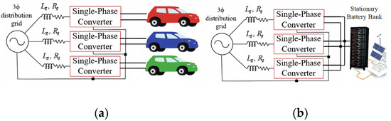
Figure 1.
Three-phase configuration of: (a) Single-phase BEVCs, (b) single-phase BBCs for stationary batteries.
For this analysis two frequency events were considered: step-shaped and ramp-shaped variations. Different inertia constant and damping factor values were evaluated to quantify the transient power response. Analytical expressions were derived to estimate the transient response parameters in active power under frequency disturbances. The proposed methodology can be useful to design specific converters implementing VI support.
The remainder of this paper is organized as follows: Section 2 details the analyzed GFM control strategy, which enables VI as well frequency and voltage droop support. Section 3 describes the design and implementation of a 1.2 kW reduced-scale prototype. Section 4 presents the analytic analysis for a step-shaped frequency event. Section 5 presents the analytic analysis for a ramp-shaped frequency event. Section 6 and Section 7 present simulation and experimental results, respectively. Section 8 compares the proposed analysis with existing techniques. Finally, Section 9 concludes the paper.
2. GFM Converter Control Strategy Implemented on a Single-Phase Isolated Bidirectional Battery Charger
The proposed converter topology consists of a dual active bridge series-resonant (DABSR) converter in the DC-DC stage, cascaded with a voltage source inverter (VSI) with an LCL filter in the DC-AC stage. The proposed control scheme consists of six control loops as illustrated in Figure 2. AC current control, active power control (APC), reactive power control (RPC), frequency droop control and voltage droop control are implemented in the DC-AC stage, whereas DC-link voltage control is implemented in the DC-DC stage.
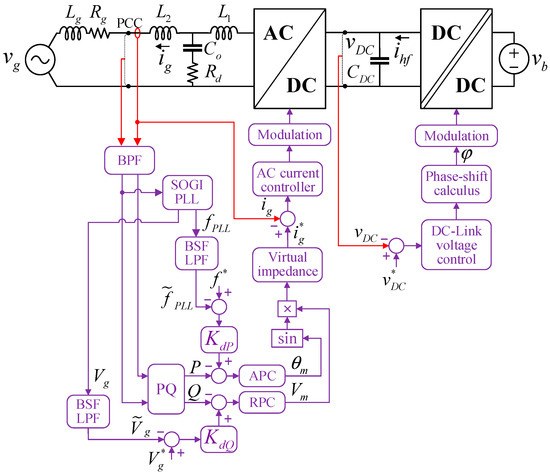
Figure 2.
Control diagram of GMF converter.
2.1. Synchronous Generator
The rotational dynamics of conventional SGs are governed by the swing equation [2], which can be expressed in per unit (p.u.) form as shown in (1). This equation includes the inertia constant H, defined in (2), which determines the RoCoF and the frequency Nadir [5] during frequency events.
where and denote the mechanical (input) and electrical (output) powers emulated by a VSM, respectively, both expressed in p.u. Similarly, and represent the rated angular frequency (rad/s) and nominal power of the VSM (VA) of the VSM.
2.2. Power Transferred Between Two Sources
The GFM converter is modeled as an AC voltage source connected to the point of common coupling (PCC) through an impedance , which represents the equivalent impedance of the LCL filter and VSM output [30,31,32]. The AC grid is modeled as an ideal AC voltage source with a series impedance . The total impedance between and is denoted by , as shown in Figure 3.
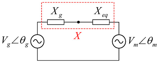
Figure 3.
Simplified model of a VSM connected to the grid.
The active power and reactive power between the two sources— and —are derived from the equivalent circuit shown in Figure 3 and are expressed in (3) and (4), respectively.
Under the assumption of small difference between and , and can be approximated by (5) and (6), respectively. This approximation indicates that is primarily governed by the phase angle difference between the two AC sources, while is mainly determined by the difference in their voltage amplitudes.
3. System Design
3.1. Band Pass Filter (BPF) and SOGI-PLL
The voltage and current signals are filtered using a BPF, which is essential to mitigate measurement errors such as DC offset insertion and to attenuate grid harmonics. The BPF is implemented using a Second Order Generalized Integrator (SOGI), where the in-phase signal serves as the filtered output. The grid frequency is estimated through a SOGI based phase-locked loop (PLL), in which the quadrature signals (αβ), determined in (7) and (8), are transformed into synchronous reference frame signals (dq).
where denotes the nominal angular frequency and represents the damping coefficient. Furthermore, the PQ block shown in Figure 2 computes the active and reactive power, as expressed in (9) and (10), respectively, using the α and β components of voltage and current measured at the PCC.
3.2. Active Power Control (APC)
The closed-loop control for active power is derived from (1) and (5). A damping factor is introduced to ensure a non-oscillatory second-order transfer function [7]. The resulting transfer function in p.u., shown in (11), is a dual-input system in which denotes the power reference, while variations in are treated as a disturbance.
where is the inverse of the equivalent reactance . For controller parameters design, only the main loop shown in (12) is considered.
is compared with a generalized-second order transfer function characterized by the natural frequency and damping factor , which are determined using (13) and (14), respectively.
3.3. Reactive Power Control (RPC)
To obtain the model, is linearized around the operating point (, , ) using partial derivates, as shown in (15). Consequently, by substituting from (6) into (15), and considering as a disturbance signal, the reactive power model is derived, considering the reactance in series with a series resistance , as shown in (16).
An integral controller, with gain denoted by , is employed to achieve a second-order closed-loop transfer function. The integral gain is designed according to the desired bandwidth [32] of the RPC loop.
3.4. Droop Control
The frequency deviations must be compensated through active power adjustments. When the grid frequency decreases, the converter increases the active power injection and vice versa. The active power-frequency droop gain is calculated by relating the maximum frequency deviation to the maximum active power delivered, as expressed in (17).
Similarly, voltage amplitude deviations must be compensated by reactive power. When the amplitude decreases, the reactive power supplied by the converter increases and vice versa. The reactive power-voltage droop gain is determined by relating the maximum voltage deviations to the maximum reactive power delivered, as expressed in (18).
3.5. AC Current Control
A PR controller is adopted for AC current regulation due to its high gain at the resonant frequency. In this control loop, the AC current controller is designed for nominal operating conditions and the LCL filter is used as a transfer function that relates the generated voltage and the grid current as shown in (19).
The inner control loop (current) must operate significantly faster than the outer control loop (active and reactive power). The PR controller, given in (20), is separated into proportional and resonant components.
The proportional gain is designed according to the desired bandwidth of this control loop and is calculated using (21). In open loop operation, approximately corresponds to the cut frequency .
To ensure a high gain at the fundamental frequency , the resonant gain must be considerably higher than according to (20). For this reason, the next consideration is established: . To avoid the influence of the resonant component near to the controller bandwidth must be narrow, typically 0.1% of .
3.6. DC-Link Voltage Control
In GFM control strategy, the DC-link voltage is regulated within the DC-DC stage. This is modeled as a controlled current source, whereas the DC-AC stage is represented as a resistive load corresponding to the nominal DC bus power, denoted by . Consequently, the DC bus dynamics can be approximated by an RC circuit as shown in (22).
Here, denotes the controlled current, calculated as the average of high-frequency rectified current from the DABSR converter, . A PI controller is proposed to implement the pole-zero cancelation strategy. Consequently, the closed-loop transfer function is reduced to a first-order system with a bandwidth denoted by . The proportional and integral gains are determined according to (23) and (24), respectively.
The converter parameters and sized components are summarized in Table 1.

Table 1.
Converter parameters.
While the calculated controller gains based on these parameters and design equations are presented in Table 2.
Table 2.
Designed gains of the controllers.
4. Virtual Inertia Calculation for a Step-Shaped Frequency Disturbance
An inertial power response of the converter is produced when a disturbance occurs in . A new transfer function, shown in (25), that relates power and the grid frequency is obtained from (11).
The transient behavior is analyzed for a step change in , characterized by the frequency variation . Considering this disturbance, the power variation in Laplace domain is expressed in (26).
To determine the transient response, the inverse Laplace transform is applied to (26). The second order transfer function yields three possible responses depending on the damping factor: underdamped (), critically damped () or overdamped () responses.
4.1. Underdamped Response
In this case, there are two complex conjugate poles , and the corresponding time-domain solution is given in (27).
To obtain the expression for calculating the maximum amplitude of the power during the transient response, (27) is differentiated whit respect to time and set equal to zero to determine the peak time . The corresponding solution is shown in (28).
For n = 0, 1, 2, …, multiple power peaks appear in the underdamped response, with the first peak being the maximum. Therefore, n = 0 is selected. With this consideration, expression (28) is replaced in (27) to obtain the analytical expression for calculate the amplitude of power peak, as shown in (29).
4.2. Critically Damped Response
For the critically damped case, the system presents two equal real poles , and the corresponding time-domain solution is shown in (30).
Differentiating (30) and setting it to zero yields the peak time, as shown in (31). Substituting (31) into (30) results in (32), which represents the power peak reached during the transient response.
4.3. Overdamped Response
In the overdamped response, the system presents two distinct real poles , and the time-domain solution is shown in (33).
Differentiating (33) respect to the time and setting it to zero yields the peak time, as shown in (34). Substituting (34) into (33) results in (35), which represents the power peak reached during the transient response.
Based on the preceding analysis, the dynamic response of the active power for VI support is modeled in MATLAB R2020b for the three cases: underdamped, critically damped and overdamped. For each case, different values of and are calculated. Two different tests were considered. In the first test, the inertia parameter was kept constant at , while was varied. In the second test, the damping factor was kept constant at , while was varied. The dynamic responses of the active power for both tests are shown in Figure 4a and Figure 4b, respectively. Note that the power peak becomes larger for small and large as is shown in Figure 4.
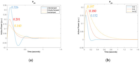
Figure 4.
Active power response under step-shaped frequency disturbance for (a) H = 5.3211, and kp = 0.005 (underdamped), kp = 0.0122 (critically damped) and kp = 0.02 (overdamped), (b) H = 2, H = 5, H = 10 and kp = 0.0141.
5. Virtual Inertia Calculation for Ramp-Shaped Frequency Variation
In a more realistic scenario, the grid frequency variation is assumed to have a ramp shape. Therefore, in this analysis, a ramp-shaped frequency disturbance with saturation, as shown in Figure 5, is used to evaluate the power response.
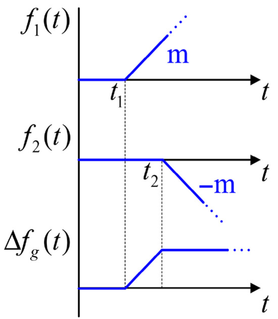
Figure 5.
Ramp-shaped frequency variation.
The functions and , defined in (36) and (37), respectively, are two ramp functions with equal slope magnitudes but opposite signs, starting at and , respectively. The grid frequency variation in Hz is represented by the function , which is given by the sum of and , as shown in (38). Hence, describes a ramp that begins at and saturates at . The parameter denotes the RoCoF of the frequency variation and represents the step function starting at .
The active-power variation in the Laplace domain, shown in (39), is derived using (25) as the model and (38) as the input. To simplify the expressions, it is assumed that . The parameters and are grouped into the constant K, as shown in (40).
The nonzero roots of (39) are denoted by and . For , the system can be expressed in partial fractions to obtain the time-domain function ΔP(t) through the inverse Laplace transform, as shown in (41). The coefficients of the solution are shown in (42).
Similarly, when , the system can be expressed in partial fractions, and ΔP(t) is obtained through the inverse Laplace transform, as shown in (43). The coefficients of the solution are shown in (44).
5.1. Underdamped Response
When the damping factor is less than 1, the response is classified as underdamped, and two complex-conjugated poles are obtained, as shown in (45). Replacing (45) in (42), the coefficients can be calculated as shown in (46).
5.2. Critically Damped Response
When the damping factor is equal to 1, the response is classified as critically damped, and two equal real poles are obtained, as shown in (47). Replacing (47) in (44), the coefficients can be calculated as shown in (48).
5.3. Overdamped Response
When the damping factor is greater than 1, the response is classified as overdamped, and two different real poles and are obtained, as shown in (49). Replacing (49) in (42) the coefficients can be calculated as shown in (50).
The dynamic response of the active power for VI support is modeled in MATLAB R2020b under a ramp-shaped frequency disturbance saturated at −0.2 Hz with a RoCoF of −1 Hz/s as is shown in Figure 6, where the grey line indicates the frequency disturbance input. The parameter values of and are the same as those used for step-shaped frequency disturbance, with the aim of comparing both transient curves obtained using the same control structure under different frequency events. Similarly to the previous analysis, the power peak increases for smaller and large .
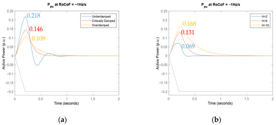
Figure 6.
Active power response under ramp-shaped frequency disturbance for (a) H = 5.3211, and kp = 0.005 (underdamped), kp = 0.0122 (critically damped) and kp = 0.02 (overdamped) and for (b) H = 2, H = 5, H = 10 and kp = 0.0141.
6. Simulation Results
The designed power converter is simulated using PSIM 2021a software. The active power responses under step-shaped and ramp-shaped frequency disturbances are shown in Figure 7 and Figure 8, respectively. The values of and used to evaluate the active power response are selected to match those of the theoretical model, enabling a direct comparison between theoretical and simulation results.
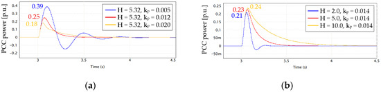
Figure 7.
Simulation results of active power response under step-shaped frequency disturbance for: (a) constant and variable , and (b) variable and constant .
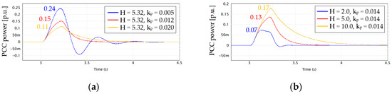
Figure 8.
Simulation results of active power response under ramp-shaped frequency disturbance for: (a) constant H and variable kp, and (b) variable H and constant kp.
The designed converter employs two SOGIs, the first one functions as a BPF, while the second generates the quadrature signals and for voltage and current. The SOGI damping factor determines both the selectivity and the dynamic response of the filtered signal. A smaller provides higher selectivity and a slower dynamic response, whereas a larger results in lower selectivity and a faster dynamic response. The value of must be chosen according to the harmonic noise level and the desired bandwidth. A BPF + SOGI with is considered in the converter design to attenuate harmonic noise and offset from the grid, the simulation results, shown in Figure 7 and Figure 8, correspond to this configuration.
The comparisons of the power peak and the settling time during the transient response between the theoretical and simulation results for step-shaped and ramp-shaped frequency disturbances are summarized in Table 3 and Table 4, respectively. The power peak observed in the transient response of active power is higher in the simulation results than in the theoretical results for all evaluated cases. This deviation is attributed to the use of filters in the calculation of active and reactive power.
Table 3.
Comparison between theoretical and experimental values under step-shaped frequency disturbance using a BPF + SOGI with .
Table 4.
Comparison between theoretical and experimental values under ramp-shaped frequency disturbance using a BPF + SOGI with .
Comparing Table 3 and Table 4, smaller errors are observed in both the power peak and the settling time for the ramp-shaped frequency disturbance. In power grids, the frequency deviation does not exhibit a step behavior, as it is physically governed by the dynamics of the generators connected to the grid. Therefore, a ramp-shaped frequency disturbance can be considered a more accurate representation of the grid behavior under frequency events. The errors of Table 4 are considerably small, indicating that a good estimation can be achieved by the previously analyzed model.
In order to analyze the influence of the method used to compute and , the theoretical results are compared with two configurations under step-shaped and ramp-shaped frequency disturbances, as shown in Figure 9 and Figure 10, respectively. The first configuration, used in the previous simulation results, employs a BPF + SOGI with , while the second uses only a SOGI with .
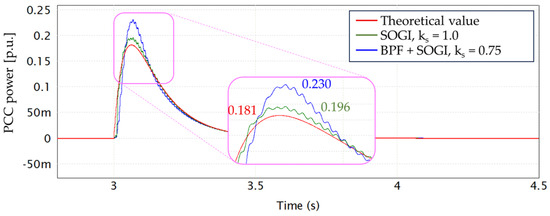
Figure 9.
Simulation of active power response under step-shaped frequency disturbance, for H = 5.321 and kp = 0.014.
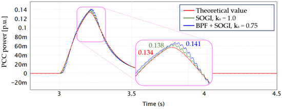
Figure 10.
Simulation of active power response under ramp-shaped frequency disturbance, for H = 5.321 and kp = 0.014.
Using only a SOGI, the power peak error decreases from 27.1% to 8.3% and from 5.2% to 3.0% under step-shaped and ramp-shaped frequency disturbances, respectively. However, the use of only SOGI does ensure adequate harmonic filtering and offset elimination, which should be considered in experimental implementation.
7. Experimental Results
The proposed control strategy is tested on a 1.2 kW power converter prototype as shown in Figure 11. The Chroma 61702 AC source (Chroma ATE Inc., Taoyuan, Taiwan)is used to emulate the grid and simulate frequency events, while the Keysight RP7951A (Keysight Technologies, Santa Rosa, CA, USA) serves as a regenerative DC source to emulate the battery.
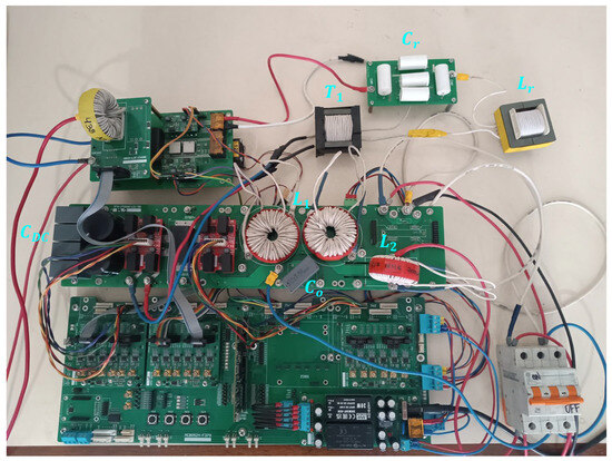
Figure 11.
1.2 kW AC-DC converter prototype.
The operating process of the power converter is illustrated in the block diagram of Figure 12. First, the DC-link voltage is regulated at 400 V in the DC-DC stage. To avoid large currents through transformer T1, the DC-link voltage reference increases gradually from 0 V to 400 V. The second step is to turn on the grid source. To prevent overcurrents in the LCL filter, an auxiliary resistor is connected in series with the AC grid. The third step is to active the DC-AC control with active and reactive power references initially set to zero to avoid overload; afterward, the auxiliary resistor is bypassed. In the fourth step, the power reference is set to operate under specific conditions, for example, 0.6 p.u. At this point, the converter is completely operative. The fifth step is to generate frequency events to evaluate the virtual inertia support capability of the power converter.
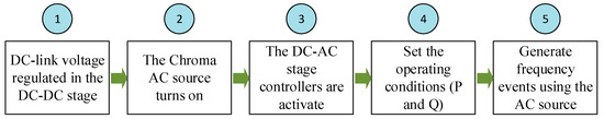
Figure 12.
Experimental process diagram.
7.1. Power Management
The AC-DC converter can operate in all four quadrants of power, managing both active and reactive power. The waveforms of voltage and current for each quadrant are shown in Figure 13. The voltage and current scales are set to 200 V/div and 5 A/div, respectively, while the time scale is set to 20 ms/div.
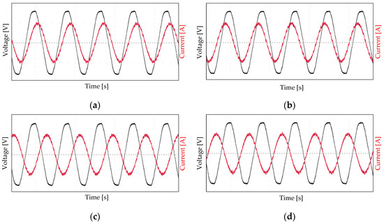
Figure 13.
Converter operation at four quadrants of power: (a) P = 600 W and Q = 450 VAR, (b) P = 600 W and Q = −450 VAR, (c) P = −600 W and Q = 450 VAR, (d) P = −600 W and Q = −450 VAR.
7.2. Power Response Under Step-Shaped Frequency Disturbance
To show only the VI support effect in the power response, the droop control is not considered. The nominal operating frequency of the AC source is 60 Hz, and it is configured to produce step-shaped frequency deviations of ±0.2 Hz, resulting in AC waveforms of 60.2 Hz and 59.8 Hz. The active power responses are shown in Figure 14a and Figure 14b, respectively. The power variation during the transient response reaches approximately 300 W within 60 ms, as designed.
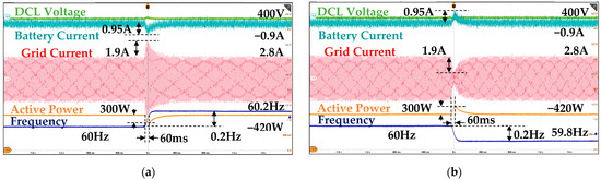
Figure 14.
Dynamic response to a step-shaped frequency disturbance of (a) +0.2 Hz and (b) −0.2 Hz, considering only virtual inertia.
GFM converters exhibit inherent inertia in their dynamics of active power during transient responses. However, the frequency deviations must be compensated through droop control at steady state. At the DC port, the battery supplies or absorbs power resulting from both effects—virtual inertia and droop control—leading to current variations of 0.95 A and 1.05 A during transient response for virtual inertia alone and virtual inertia combined with the droop effect, respectively. Step-shaped frequency variations in +0.2 Hz and −0.2 Hz are simulated by the AC source, and the resulting transient power responses, which combine both effects, are shown in Figure 15a and Figure 15b, respectively.
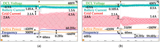
Figure 15.
Dynamic response to a step-shaped frequency disturbance of (a) +0.2 Hz and (b) −0.2 Hz, considering virtual inertia and droop control.
7.3. Power Response Under Ramp-Shaped Frequency Disturbance
In this case the power converter is tested under ramp-shaped frequency disturbances with RoCoFs of +1 Hz/s and −1 Hz/s. The transient power responses are shown in Figure 16a and Figure 16b, respectively.
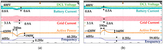
Figure 16.
Dynamic response to a ramp-shaped frequency disturbance with a RoCoF of (a) +1 Hz/s and (b) −1 Hz/s, considering only virtual inertia.
The Chroma 61702 AC source is programmed to produce a ramp-shaped frequency variation. However, since programming is based on establishing specific frequency points over time, the results may exhibit small mismatches. This is evident when comparing Figure 16a,b: at the start of the ascending ramp, the waveform is not a well-defined straight line, in contrast to the descending ramp. This explains the differences observed in the power transient responses between the two cases.
By modifying the RoCoF to +0.5 Hz/s and −0.5 Hz/s, the transient power responses are shown in Figure 17a and Figure 17b, respectively. Similarly to the previous test, there are small differences between the ascending and descending ramps, which explain the differences observed in the power transient responses between the two cases.
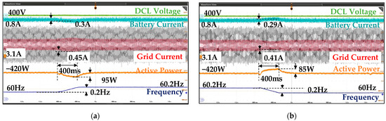
Figure 17.
Dynamic response to a ramp-shaped frequency disturbance with a RoCoF of (a) +0.5 Hz/s and (b) −0.5 Hz/s, considering only virtual inertia.
7.4. Voltage Response
Grid voltage amplitude step of ±15.5 V is emulated using the AC source as shown in Figure 18. Reactive power exhibits both fast and slow dynamics, attributed to the system’s inherent inertia and the droop control, respectively. The battery current remains almost constant at 0.7 A, showing only a slight deviation when the amplitude step occurs.
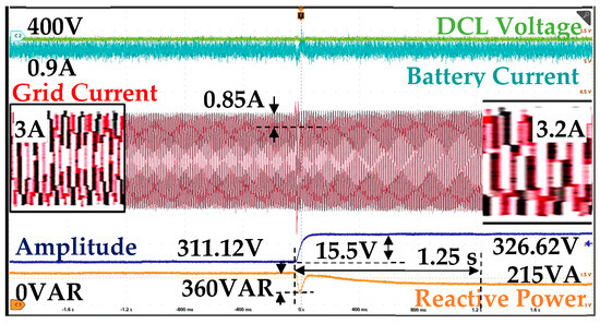
Figure 18.
Dynamic response to a voltage step disturbance of +15.5 V.
8. Discussion
Virtual inertia is necessary to enhance RoCoF and frequency Nadir. In addition, galvanic isolation is required for security. Furthermore, it is important to remark that power support must consider overload capacity to avoid converter failures. On the other hand, GFL strategy is limited managing current in strong grids where frequency and amplitude variations are not a major problem. Therefore, the proposed work achieves all the indicated requirements for practical applications, contributing to overall system stability.
The inclusion of these control mechanisms in a single-phase system represents a feasible alternative for distributed support applications, considering that single-phase units can operate in a coordinated manner to provide balanced support or differentiated responses under grid imbalance conditions.
Strategies to implement V2G functionalities have been validated in works such as [28,29,30,31]. However, the concept of Distributed Virtual Inertia (DVI) requires certain considerations that were not included in previous works. The key parameters used to compare this work with similar approaches are summarized in Table 5.
Table 5.
Comparison with other studies.
A procedure to estimate the amount of power support using the GFL approach is detailed in [12]. However, in the state of the art, no such procedure exists when the GFM strategy is employed. In this case, the analysis of the equations modeling the behavior of a synchronous machine allowed the evaluation of the impact of the inertia constant and the damping factor on the active power control loop. This theoretical framework enabled the estimation of the active power peak generated in response to step-shaped and ramp-shaped frequency disturbances, establishing a direct relationship between the control parameters and the magnitude of the system response. The results show that increasing leads to a higher active power peak during frequency disturbances, while acts to limit this overshoot and provide adequate damping, offering a practical means to shape the dynamic behavior of the system. A comparison between the proposed work and ref. [28] is shown in Figure 19.
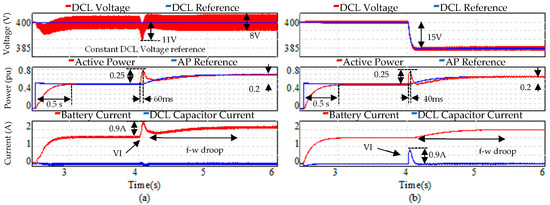
Figure 19.
Dynamic response for full frequency support using (a) Proposed work: GFM and only a battery. (b) GFL and a HESS [28].
It is important to highlight that the proposed strategy relies exclusively on the battery as the sole energy source for both fast and slow dynamic responses. While this simplifies the system architecture, it also emphasizes the need to consider stationary battery systems with sufficient capacity to sustain the required energy exchanges, particularly under demanding dynamic conditions. To avoid this limitation, the use of the capacitance in DC-Link will be analyzed in future work.
Finally, differences were observed between the estimated and experimental results, especially when the frequency variation dynamics are faster, as in the case of ramp-shaped frequency disturbances. The difference is mainly attributed to the use of filters in the calculation of active and reactive power, which introduces a delay in the power loop response and leads to slightly higher overshoots than those predicted by the model. Although these differences do not compromise the effectiveness of the proposed strategy, a more detailed analysis of the filter design is planned for future work to improve the correlation between the theoretical model and the experimental behavior.
9. Conclusions
The analytical model of VI responses based on a GFM control strategy implemented in a power converter is presented in this article, with the aim of calculating the transient of the active power response for VI support. The analysis shows that the inertia constant and the damping coefficient used in the active power controller have a strong influence on the power response for VI support, resulting in three types of dynamics behavior: underdamping, critically damping and overdamping. Using the obtained function transfer models, the transient of the active power response was evaluated for two types of grid frequency disturbances—step-shaped and ramp-shaped. To verify the analytic model, a prototype of a 1.2 kW two-stage AC-DC converter was designed, implementing the GFM control strategy. The simulation and experimental results show that the analytic model presents a considerable error for a step-shaped frequency disturbance, whereas under a ramp-shaped frequency disturbances the error is minimal for overdamped mode. This last result is important because real grid frequency variations are more similar to ramp-shaped than step-shaped profiles. The obtained results can be used to properly size future power converter implementing VI support. Future studies will focus on evaluating the results for different GFM control strategies and under weak-grid conditions.
Author Contributions
E.P., J.P. and D.S.y.R. contributed to the research, investigation, results analysis, resources, and writing—review and editing. All authors have read and agreed to the published version of the manuscript.
Funding
This work was supported by Concytec-Prociencia by the project “Manufactura e integración de Estaciones de Recarga DC y AC para Vehículos Eléctricos en las redes de distribución eléctrica peruana con Generación Fotovoltaica” [Contract N° PE501079641-2022-PROCIENCIA].
Data Availability Statement
The original contributions presented in this study are included in the article. Further inquiries can be directed to the corresponding author.
Conflicts of Interest
The authors declare no conflicts of interest.
References
- Alam, M.S.; Al-Ismail, F.S.; Salem, A.; Abido, M.A. High-Level Penetration of Renewable Energy Sources into Grid Utility: Challenges and Solutions. IEEE Access 2020, 8, 190277–190299. [Google Scholar] [CrossRef]
- Du, W.; Tuffner, F.K.; Schneider, K.P.; Lasseter, R.H.; Xie, J.; Chen, Z.; Bhattarai, B. Modeling of Grid-Forming and Grid-Following Inverters for Dynamic Simulation of Large-Scale Distribution Systems. IEEE Trans. Power Deliv. 2021, 36, 2035–2045. [Google Scholar] [CrossRef]
- Fang, J.; Li, H.; Tang, Y.; Blaabjerg, F. On the Inertia of Future More-Electronics Power Systems. IEEE J. Emerg. Sel. Topics Power Electron. 2019, 7, 2130–2146. [Google Scholar] [CrossRef]
- Jafari, M.; Gharehpetian, G.B.; Anvari-Moghaddam, A. On the Role of Virtual Inertia Units in Modern Power Systems: A Review of Control Strategies, Applications and Recent Developments. Int. J. Electr. Power Energy Syst. 2024, 159, 110067. [Google Scholar] [CrossRef]
- Shobug, M.A.; Chowdhury, N.A.; Hossain, M.A.; Sanjari, M.J.; Lu, J.; Yang, F. Virtual Inertia Control for Power Electronics-Integrated Power Systems: Challenges and Prospects. Energies 2024, 17, 2737. [Google Scholar] [CrossRef]
- Khajehoddin, S.A.; Karimi-Ghartemani, M.; Ebrahimi, M. Grid-Supporting Inverters with Improved Dynamics. IEEE Trans. Ind. Electron. 2019, 66, 3655–3667. [Google Scholar] [CrossRef]
- Qoria, T.; Rokrok, E.; Bruyere, A.; François, B.; Guillaud, X. A PLL-Free Grid-Forming Control with Decoupled Functionalities for High-Power Transmission System Applications. IEEE Access 2020, 8, 197363–197378. [Google Scholar] [CrossRef]
- Fang, J.; Li, H.; Tang, Y.; Blaabjerg, F. Distributed Power System Virtual Inertia Implemented by Grid-Connected Power Converters. IEEE Trans. Power Electron. 2018, 33, 8488–8499. [Google Scholar] [CrossRef]
- Peng, Q.; Fang, J.; Yang, Y.; Liu, T.; Blaabjerg, F. Maximum Virtual Inertia From DC-Link Capacitors Considering System Stability at Voltage Control Timescale. IEEE J. Emerg. Sel. Top. Circuits Syst. 2021, 11, 79–89. [Google Scholar] [CrossRef]
- Fang, J.; Lin, P.; Li, H.; Yang, Y.; Tang, Y. An Improved Virtual Inertia Control for Three-Phase Voltage Source Converters Connected to a Weak Grid. IEEE Trans. Power Electron. 2019, 34, 8660–8670. [Google Scholar] [CrossRef]
- Quan, X.; Yu, R.; Zhao, X.; Lei, Y.; Chen, T.; Li, C.; Huang, A.Q. Photovoltaic Synchronous Generator: Architecture and Control Strategy for a Grid-Forming PV Energy System. IEEE J. Emerg. Sel. Top. Power Electron. 2020, 8, 936–948. [Google Scholar] [CrossRef]
- Paucara, J.; Peña, J.; Espinoza, R.; Sal y Rosas, D. Control Strategy to Provide Frequency Support Functionality Using a Supercapacitor-Based Energy Storage System. In Proceedings of the 2021 IEEE Vehicle Power and Propulsion Conference (VPPC), Gijon, Spain, 25–28 October 2021. [Google Scholar] [CrossRef]
- Liu, T.; Dai, Y.; Peng, Q.; Zeng, X.; Chen, G.; Meng, J. Inertia Emulation-Oriented Evaluation Method of Sustaining Power Boundary for Lithium-Ion Battery Energy Storage System. IEEE Trans. Energy Convers. 2024, 39, 2362–2376. [Google Scholar] [CrossRef]
- Wu, Q.; Chu, X.; Fan, Y.; Liu, L.; Sun, X. Consistency Algorithm-Based SOC Balancing Scheme of Retired Non-Equal Capacity Lithium Battery in Virtual Synchronous Generator Controlled Microgrids. IEEE Access 2025, 13, 9073–9088. [Google Scholar] [CrossRef]
- Dozein, M.G.; De Corato, A.M.; Mancarella, P. Virtual Inertia Response and Frequency Control Ancillary Services From Hydrogen Electrolyzers. IEEE Trans. Power Syst. 2023, 38, 2447–2459. [Google Scholar] [CrossRef]
- Reißner, F.; De Carne, G. Virtual Synchronous Machine integration on a Commercial Flywheel for Frequency Grid Support. IEEE Trans. Power Electron. 2024, 39, 12086–12090. [Google Scholar] [CrossRef]
- Sarojini, R.K.; Palanisamy, K.; Sanjeevikumar, P.; Nielsen, J.B.-H. Inertia emulation control technique based frequency control of grid connected single-phase rooftop photovoltaic system with battery and supercapacitor. IET Renew. Power Gener. 2020, 14, 1156–1163. [Google Scholar] [CrossRef]
- Fang, J.; Tang, Y.; Li, H.; Li, X. A battery/ultracapacitor hybrid energy storage system for implementing the power management of virtual synchronous generators. IEEE Trans. Power Electron. 2018, 33, 2820–2824. [Google Scholar] [CrossRef]
- Sun, C.; Ali, S.Q.; Joos, G.; Bouffard, F. Design of Hybrid-Storage-Based Virtual Synchronous Machine With Energy Recovery Control Considering Energy Consumed in Inertial and Damping Support. IEEE Trans. Power Electron. 2022, 37, 2648–2666. [Google Scholar] [CrossRef]
- Bernal, M.; Rocca, R.; Fernández, G.; Paz, M.; Galán, N. Grid Impact of Frequency Regulation Provided by V2Gs Aggregated at HV, MV, and LV Level. IEEE Access 2023, 11, 76768–76780. [Google Scholar] [CrossRef]
- Liu, T.; Wang, P.; Peng, Q.; Zhang, M.; Wang, T.; Meng, J. Operation-area-constrained Adaptive Primary Frequency Support Strategy for Electric Vehicle Clusters. J. Mod. Power Syst. Clean Energy 2023, 11, 1982–1994. [Google Scholar] [CrossRef]
- Kaur, K.; Singh, M.; Kumar, N. Multiobjective Optimization for Frequency Support Using Electric Vehicles: An Aggregator-Based Hierarchical Control Mechanism. IEEE Syst. J. 2019, 13, 771–782. [Google Scholar] [CrossRef]
- Amamra, S.-A.; Marco, J. Vehicle-to-grid aggregator to support power grid and reduce electric vehicle charging cost. IEEE Access 2019, 7, 178528–178538. [Google Scholar] [CrossRef]
- Restrepo, M.; Morris, J.; Kazerani, M.; Cañizares, C.A. Modeling and testing of a bidirectional smart charger for distribution system EV integration. IEEE Trans. Smart Grid 2018, 9, 152–162. [Google Scholar] [CrossRef]
- Kazemtarghi, A.; Dey, S.; Mallik, A. Optimal Utilization of Bidirectional EVs For Grid Frequency Support in Power Systems. IEEE Trans. Power Deliv. 2023, 38, 998–1010. [Google Scholar] [CrossRef]
- Roveri, A.; Mallemaci, V.; Mandrile, F.; Bojoi, R. Power Decoupling Methods for Grid Support Provided by Ultra-Fast Bidirectional Chargers. IEEE Open J. Ind. Electron. Soc. 2025, 6, 107–119. [Google Scholar] [CrossRef]
- Ke, S.; Ding, L.; Shi, X.; Fan, P.; Wang, H.; Chen, L.; Yang, J.; Chung, C.Y. Response Characteristics and Regulation Feasibility of DC Charging Station Controlled by GFM/GFL Virtual Inertia for Grid Frequency Stability. IEEE Trans. Transp. Electrif. 2025, 11, 7743–7758. [Google Scholar] [CrossRef]
- Paucara, J.D.; Peña, J.C.U.; Sal y Rosas, D. HESS Management for Virtual Inertia, Frequency, and Voltage Support Through Off-Board EV Bidirectional Chargers. IEEE Open J. Ind. Electron. Soc. 2024, 5, 376–385. [Google Scholar] [CrossRef]
- Suul, J.A.; D’Arco, S.; Guidi, G. Virtual Synchronous Machine Based Control of a Single-Phase Bi-directional Battery Charger for Providing Vehicle-to-Grid Services. IEEE Trans. Ind. Appl. 2016, 52, 3234–3244. [Google Scholar] [CrossRef]
- Sal y Rosas, D.; Zarate, A. Single-Phase Grid-Forming Strategy with Power Decoupling Implementation for Electrolytic-Capacitor-Free EV Smart Battery Charger. Energies 2023, 16, 894. [Google Scholar] [CrossRef]
- Bhowmik, P.; Satpathy, P.R.; Thanikanti, S.B.; Jana, N. A novel virtual inertia emulation technique for the single-phase electric vehicle charging topology. Comput. Electr. Eng. 2022, 101, 108114. [Google Scholar] [CrossRef]
- Pantaleon, E.; Sal y Rosas, D.; Tafur, J. Single-Phase Grid Forming Control Strategy for an Isolated and Bidirectional EV Battery Charger. In Proceedings of the 2024 Energy Conversion Congress & Expo Europe (ECCE Europe), Darmstadt, Germany, 2–6 September 2024. [Google Scholar]
- Jafari, H.; Moghaddami, M.; Olowu, T.O.; Sarwat, A.I.; Mahmoudi, M. Virtual Inertia-Based Multipower Level Controller for Inductive Electric Vehicle Charging Systems. IEEE J. Emerg. Sel. Top. Power Electron. 2021, 9, 2447–2459. [Google Scholar] [CrossRef]
- Kundur, P. Power System Stability and Control; McGraw-Hill Education: Columbus, OH, USA, 1994. [Google Scholar]
- Su, K.; Xie, X.; Gong, Z.; Liu, H.; Sun, D.; Wang, Y. Fast Frequency Response Analysis for Grid-Following and Grid-Forming Controlled BESS Considering Voltage Coupling Effect. IEEE Trans. Power Deliv. 2025, 40, 2412–2425. [Google Scholar] [CrossRef]
- Rocabert, J.; Garcia, B.; Candela, J.I.; Villón, J.D.; Rodriguez, P. Evaluation of the Grid-Forming Inertial Response for Power Reference and Grid-Supporting Functionalities. In Proceedings of the 2024 IEEE 15th International Symposium on Power Electronics for Distributed Generation Systems (PEDG), Luxembourg, 23–26 June 2024; pp. 1–6. [Google Scholar]


Disclaimer/Publisher’s Note: The statements, opinions and data contained in all publications are solely those of the individual author(s) and contributor(s) and not of MDPI and/or the editor(s). MDPI and/or the editor(s) disclaim responsibility for any injury to people or property resulting from any ideas, methods, instructions or products referred to in the content. |
© 2025 by the authors. Licensee MDPI, Basel, Switzerland. This article is an open access article distributed under the terms and conditions of the Creative Commons Attribution (CC BY) license (https://creativecommons.org/licenses/by/4.0/).