1. Introduction
With the developing technology in recent years, speed sensorless induction motor (IM) control has become increasingly important because of IM’s low cost, widespread use, and advanced drive technology [
1]. Depending on the application, the speed sensorless IM drives require the estimation of rotor speed (
) as well as the stator stationary axis components of stator (
and
) or rotor fluxes (
and
) [
2]. To carry out these estimations, various state observers/estimators have been proposed in the literature such as model reference adaptive systems (MRAS) [
3], Kalman filter-based observers [
4,
5], Luenberger observer [
6,
7], and sliding mode observer (SMO) [
8,
9].
Conventional MRAS estimators suffer from the use of pure integrators and performance degradation due to parameter changes. To overcome these problems, different adaptation methods are used in the adaptation mechanism of the MRAS estimators in the literature such as least mean square and least mean Kurtosis algorithms [
10]. Furthermore, hybrid structures are used to make MRAS methods robust against parameter variations [
11]. Additionally, Kalman filter-based solutions are employed because they can conduct real-time estimations of states and parameters, accounting for system/process errors and measurement noises directly [
4]. However, the obvious drawbacks of Kalman filter-based methods are difficulties in implementing them in a digital signal processor (DSP) due to their high complexity [
12] and the laborious selection process of noise covariance matrices [
13]. On the other hand, considering the extended Luenberger method, the pole-placement process needs to be performed by determining an appropriate gain matrix selection, which can be classified as one of the difficulties of this method [
7] together with its sensitivity to changes in IM parameters.
Compared to other estimators/observers detailed above, the advantages of the sliding mode observer (SMO) can be given as low computational load, ease in implementation to DSP, and higher performance against uncertainties [
14,
15]. As is known, correct determinations of the model parameter values play a key role in the performance of the estimators/observers. Even if the IM parameter values are well determined, the observer and thus control performance may not be satisfying because of the parameter variations caused by the temperature, frequency, and flux level changes [
16]. Since SMO is classified as a robust method, various SMO-based studies have been conducted on state/parameter estimation of IMs [
17,
18,
19]. Due to the fact that parameter variations—particularly the stator and rotor resistances (
and
) in the low-speed region and the magnetizing inductance (
) in the field-weakening region—cause performance deterioration, the rotor speed (
)-estimation performance of SMO has been improved in the literature through the online estimation of these varying parameters. In Wang et al. [
20], a second-order SMO is combined by MRAS to perform
estimation along with
estimation. In Mezouar et al. [
21], the
estimation is performed together with the inverse of the rotor time constant. In Zaky et al. [
22], the
estimation is carried out to improve
using SMO-based parallel identification schemes. Moreover, the
estimation is also performed in the field-weakening region operation. Furthermore, to improve the
estimation performance, there are also hybrid structures utilized in the literature, as in Shen et al. [
23], which uses a fuzzy dual sliding mode MRAS structure. Together with the advantages of the SMO technique, it also has some weaknesses such as chattering and parameter dependency since it is still a model-based method, and required time to reach the sliding surface. To overcome these problems, many SMO algorithms have been proposed so far, called first [
24], high-order [
25], and reaching law-based SMOs [
8,
26].
Given the different SMO algorithms, super-twisting SMO (STSMO) is one of the most well-known high-order SMO methods [
9,
27,
28]. High-order SMOs are generally proposed to solve the chattering phenomenon in the first-order SMOs [
29]. However, as stated in Gonzalez et al. [
30], STSMOs do not compensate time-varying disturbances/uncertainties if they are designed with constant switching gains. Moreover, to solve chattering problems caused by the nature of conventional SMOs (C-SMOs) as in [
24], fuzzy-based algorithms have been developed instead of the signum function used in C-SMOs [
31]. Moreover, the sliding mode control law equations of high-order SMOs, such as STSMO, involve a relatively high computational load and include pure integration, as seen in Nurettin and Inanc [
9] and Ammar et al. [
28]. Additionally, other studies aim to eliminate the chattering components observed at the system output by employing a low-pass filter during rotor flux estimation [
24,
32]. However, in this case, it causes a delay in speed estimation and an error in amplitude [
19]. To solve this problem, a continuous hyperbolic tangent function is used instead of a low-pass filter [
33]. Nevertheless, this method only guarantees the convergence of the sliding motion to the sliding surface. Furthermore, the chattering issue still persists due to the high switching gain (
) [
19]. Since using a constant
leads to chattering and performance degradation—particularly in the low-speed region—the value of
needs to be adjusted based on the operating conditions of IM. In addition to the aforementioned SMO techniques, adaptive SMO (A-SMO) methods that adjust
dynamically have also been proposed in the literature. A-SMOs have many advantages for speed estimation such as adaptation of switching gain and reduction in chattering problem in low-speed operation [
9,
18,
19,
20,
25,
34,
35,
36,
37,
38,
39,
40]. There are different approaches in the literature related to A-SMOs, which have observer gain adaptations and
or switching coefficient adaptation. The observer gain is changed depending on the IM parameters and
[
34,
35,
37]. When it comes to [
9,
18,
19,
25,
36,
38,
39,
40,
41,
42], Keyhani et al. [
36] and Tarchala and Orlowska-Kowalska [
38] propose a speed-adaptive SMO with a sliding surface defined as a function of stator current (
and
) errors and rotor fluxes. Here, the
estimation is performed by multiplying the determined sliding surface and an adaptive
; the adaptive
is obtained using a first-order polynomial of
in both studies. In Hu et al. [
39], an A-SMO is designed with a sliding surface determined as the stator current errors and the adaptive
values for each axis (
and
) are calculated as a function of IM parameters, the estimated states (
,
,
,
, and
), and determined additional gain term. Therefore, the adaptive
value depends on the IM parameters, which results in the parameter sensitivity. Moreover, the trial and error method-based determination process of the additional gain terms can also be evaluated as a second drawback of the proposed method. In Kousalya and Singh [
18], an adaptive STSMO (A-STSMO) is proposed with a sliding surface determined as the stator current errors. The speed-adaptive switching coefficients in STSMO are separately determined as functions of rotor speed and rotor speed squared. In Nurettin and Inanc [
9], an A-STSMO with the same sliding surface defined in Kousalya and Singh [
18] and Prince and Yoon [
27] is proposed. Contrary to Kousalya and Singh [
18], four switching coefficients, two for each axis, are used. One of the switching coefficients for each axis (
and
) is determined as constant while the other is adaptively calculated. Similar to Hu et al. [
39] and Zerzeri et al. [
42], the IM parameters, estimated states (
,
,
,
, and
), and additional gain term are utilized in the determination of adaptive switching coefficients. In Sun et al. [
19], an adaptive nonsingular terminal SMO (A-NTSMO) is introduced with a second-order nonsingular terminal sliding mode surface. Here, a speed-adaptive coefficient is used in A-NTSMO which contains a couple of constant coefficients to be determined. Therefore, the determination process of these constant coefficients can be evaluated as the difficulty of the proposed method. Wang et al. [
25] and Bu et al. [
43] propose a discrete SMO-based MRAS method with speed adaptation to avoid the chattering problem. The proposed discrete SMO-based MRAS in [
25] is compared to existing STSMO-based MRAS with speed adaptation. In Wang et al. [
41], a speed-adaptive high-order SMO is proposed to achieve finite-time convergence, and the method is compared with first-order and super-twisting SMOs. Two coefficients of the defined high-order sliding surface are selected as constants. Moreover,
is obtained as a first-order polynomial, independent of the estimated synchronous speed derived from the high-order SMO-based MRAS. In Bai et al. [
40], an adaptive SMO structure that uses a continuous switching function instead of the
function to suppress the chattering effect is proposed. In the proposed method, the
value is determined as the sum of the rotor speed and a constant coefficient, aiming to improve the performance in estimating the rotor speed and position information of the permanent magnet synchronous motor (PMSM). However, the method used in this study to reduce the required time to approach the sliding surface also introduces a pure integration problem.
The main contribution of this paper is to propose two novel A-SMOs to overcome the operation speed region-based performance-deterioration problem of C-SMO as in [
24] by changing the
value. The proposed A-SMOs use only the current errors in the sliding surface, similar to past studies [
9,
39] but with different adaptive mechanisms that are mathematically simpler and parameter-independent. This reality can be discovered by inspecting the adaptive mechanisms (Equation (
23) in Nurettin and Inanc [
9] and Equation (
20) in Hu et al. [
39]) which additionally require the estimated and/or measured states (flux and/or stator currents) and varying parameters (rotor time constant,
etc.); thus, the proposed adaptive mechanisms in this paper are more convenient than those of past studies [
9,
39] for real-time high performance control of industrial systems and electrical vehicles (EVs) requiring for speed sensorless drives. For
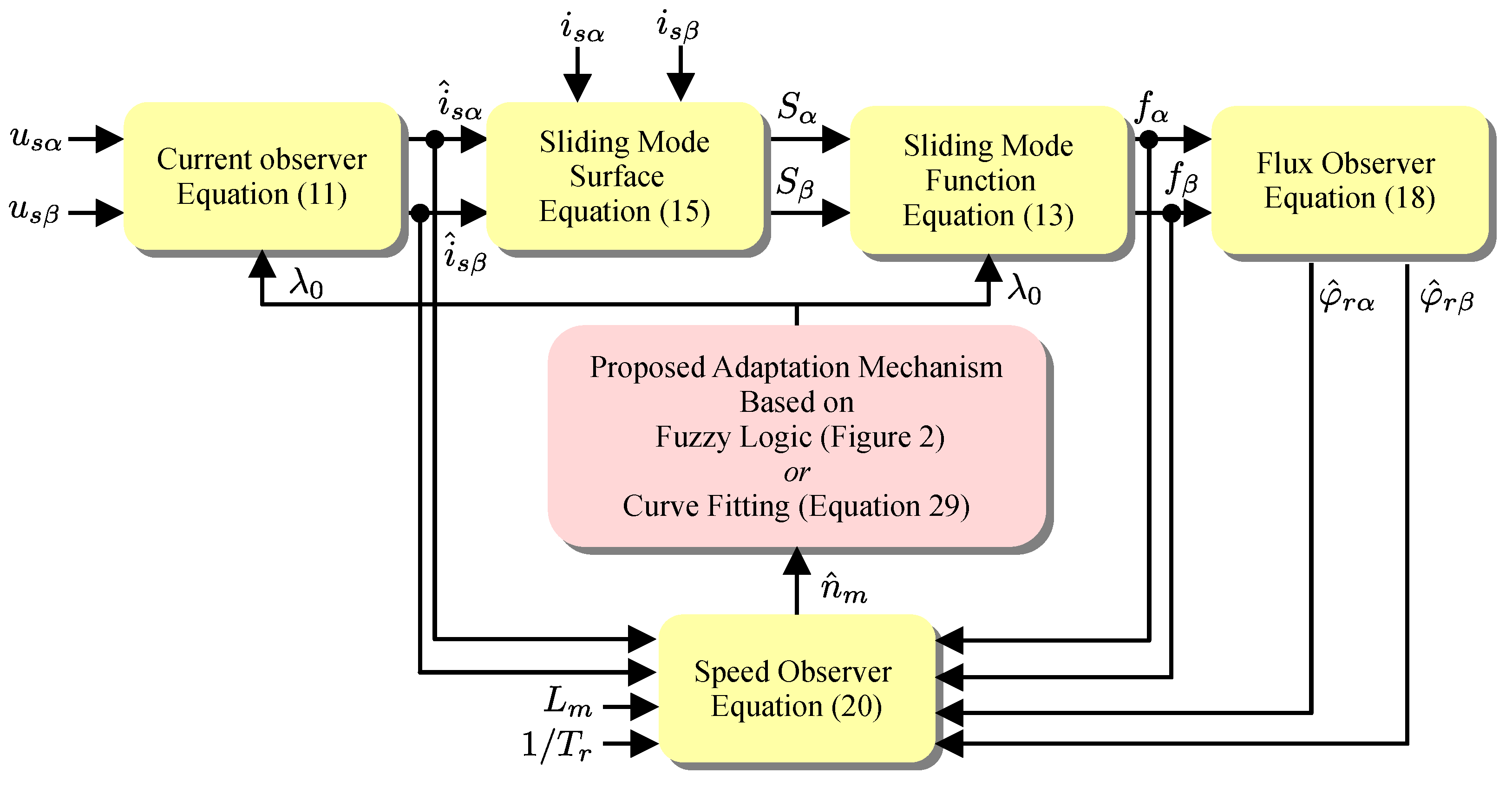
adaptation based on the operating speed, fuzzy logic and curve fitting methods are employed in the design of the proposed adaptive mechanisms. The motivation behind selecting these methods is that they introduce only a slight increase in computational load compared to the conventional SMO (C-SMO) [
24], while also being parameter-independent and computationally simpler than those used in previous studies [
9,
39]. Since A-SMO with proposed adaptive mechanisms does not lead to a significant computational load increase, they can easily be used in the high performance control of EV and industrial systems. Therefore, the low-computational load characteristic, one of the most favourable sides of C-SMO [
24], is also used in this paper. Moreover, the proposed A-SMOs with the online estimations of
,
,
,
, and
only utilize measured stator voltages (
and
) as well as
and
. To show the effectiveness of the proposed fuzzy adaptive SMO (FA-SMO) and curve-fitting adaptive SMO (CFA-SMO) methods, they are tested in real-time experiments including wide speed range operation of IM with/without load torque changes. Additionally, the estimation performances of the proposed methods are fairly compared with that of C-SMO through real-time experiments in which all observers operate in parallel at the open-loop condition. Furthermore, to examine the effect of the parameter variation over the proposed A-SMOs and C-SMO, variations in
and
are performed in the low-speed region while the
-change is realized in the high-speed operation. Finally, the obtained experimental results demonstrate the superiority of the proposed
adaptive methods in this paper over C-SMO. Moreover, the experimental results clearly indicate that the proposed A-SMOs are highly promising candidates for sensorless IM drives utilized in both industrial and EV applications. In summary, the proposed methods in this study (FA-SMO and CFA-SMO) are different from:
Nurettin and Inanc [
9] utilizing STSMO and its adaptation mechanism sensitive to the parameters and states of IM.
Kousalya and Singh [
18] exploiting STSMO with the separately determined speed-adaptive two switching coefficients as functions of rotor speed and rotor speed squared, which results in problematic operations at zero speed, making both switching coefficients zero.
Hu et al. [
39] using C-SMO and its adaptation mechanism sensitive to the parameters and states of IM.
Wang et al. [
41] employing the high-order SMO defined with a mathematically complex sliding surface and the speed estimation performed by the high-order SMO-based MRAS.
This paper consists of five sections.
Section 1 presents the literature review and the contribution of this study.
Section 2 presents the dynamic model of IM and C-SMO equations.
Section 3 explains FA-SMO and CFA-SMO to perform
estimation.
Section 4 presents the experimental setup, and shows the real-time results for C-SMO and the proposed A-SMOs to demonstrate the effectiveness of the proposed methods. Finally,
Section 5 provides the conclusion.
4. Experimental Results
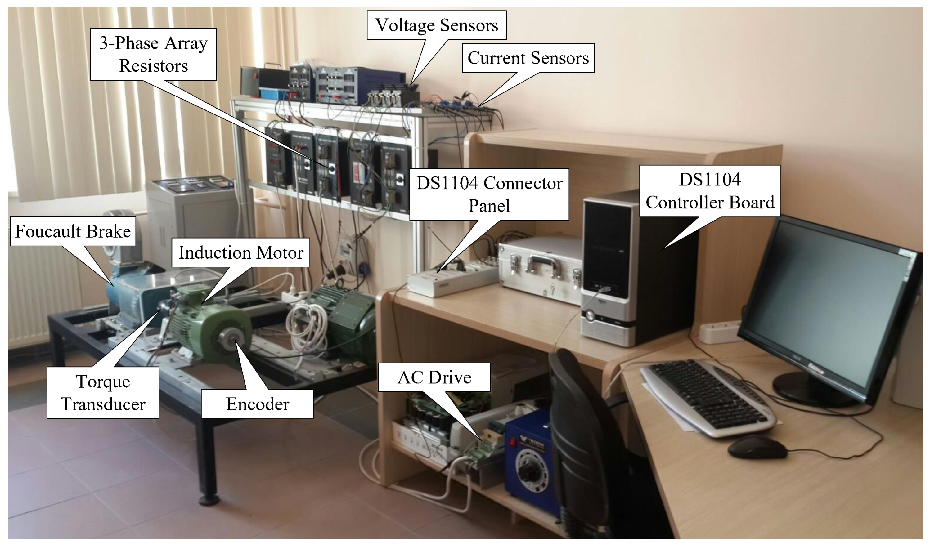
To test the proposed A-SMOs and demonstrate their superiority over C-SMO, they are tested in real-time experiments including a wide range of speeds with and without load variations. The experimental setup used in these tests is given in
Figure 7, and its block diagram representation is illustrated in
Figure 8. Here, a 30 N·m Foucault brake is used to load the three-phase squirrel-cage IM parameters which are presented in
Table 2. To perform
and
measurements, LA55-P/SP1 and LV 100–400 transducers are used, respectively. Moreover,
and
are measured by using an encoder with 5000 lines/rev and a 50 N·m torque transducer, respectively. As seen in
Figure 8, the
and
measurements are not utilized in the proposed A-SMOs and the C-SMO methods. The
is measured only to validate the
estimated by the proposed and conventional observers. Additionally, the
measurement is carried out to monitor the load condition under which IM operates. Furthermore, a three-phase array resistor is employed to externally add resistances in series
with the stator windings of the IM in order to investigate the effect of variations on the proposed A-SMOs and C-SMO. As shown in
Figure 8, to ensure a fair comparison between the proposed A-SMOs and C-SMO, all observers are operated and tested under open-loop conditions, and an AC drive is utilized to drive the IM with pulse-width modulated voltages and currents as in [
5]. The proposed A-SMOs and the C-SMO methods were designed in the Matlab S-function block, using C/C++ language, and implemented on the DS1104 controller board. For online visualization of the data in real-time experiments, the dSPACE ControlDesk interface software is used. Utilizing the data-saving feature of ControlDesk, all data presented in this paper are saved and then plotted by using Matlab to provide high-quality figure presentations. Here, the sampling time (
T) is 100
s for all tests. Also, as in [
13], proposed A-SMOs are operated simultaneously and separately from the AC drive with utilization of
and
applied to IM, and the AC drive also runs in open-loop.
By utilizing the experimental setup in
Figure 7 and
Figure 8, the proposed A-SMOs are tested under challenging scenarios including usage of measured and estimated current, zero speed operation, load variations, and parameter changes (
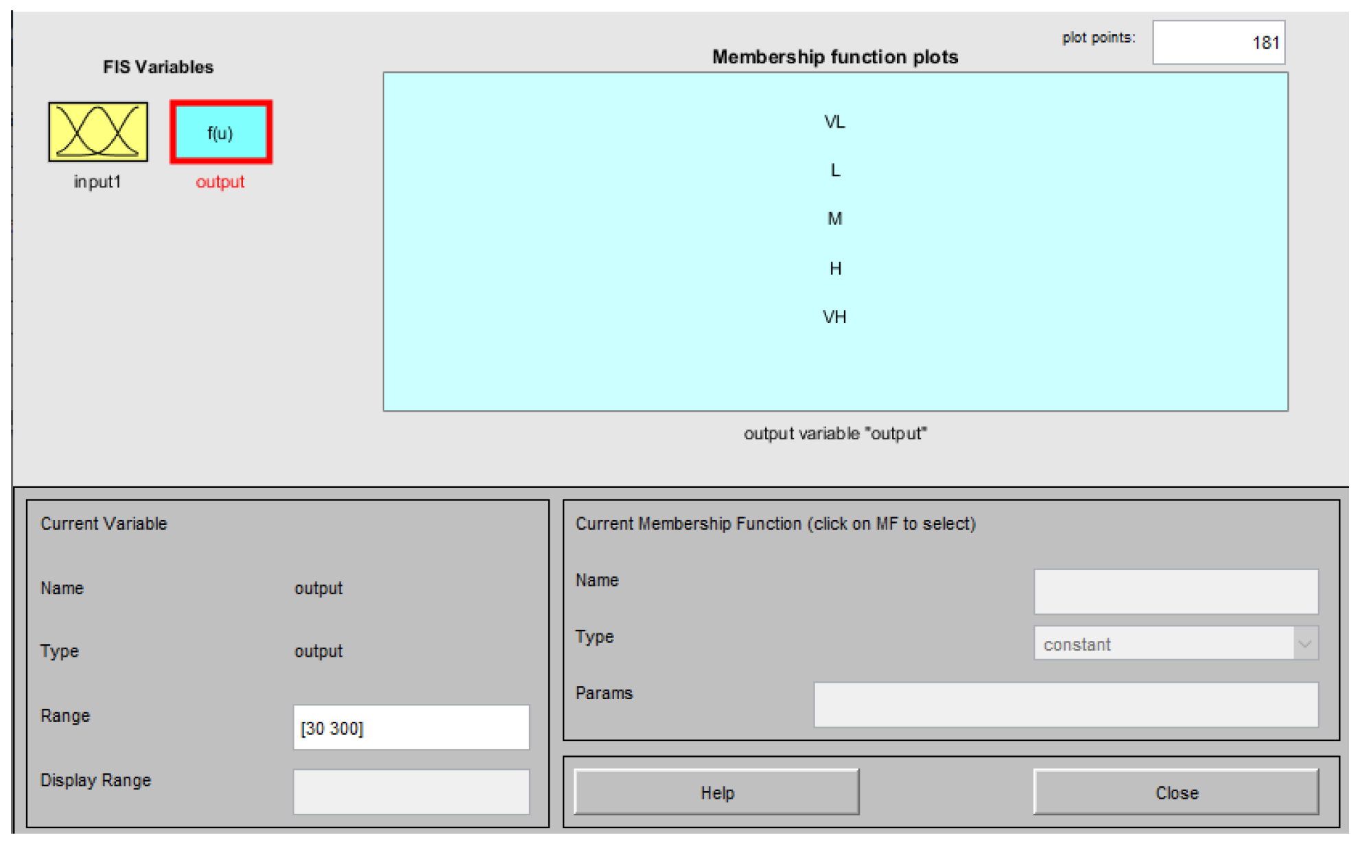
changes). In the real-time implementation of the proposed FA-SMO, the fuzzy logic controller is converted into a 1D look-up table to reduce the computational load and also the additional computational load caused by the proposed adaptive structures is obtained by measuring the execution time of each algorithm. Furthermore, the proposed A-SMOs are compared to C-SMO in all test scenarios. The details of the test scenarios are presented in the following subsections.
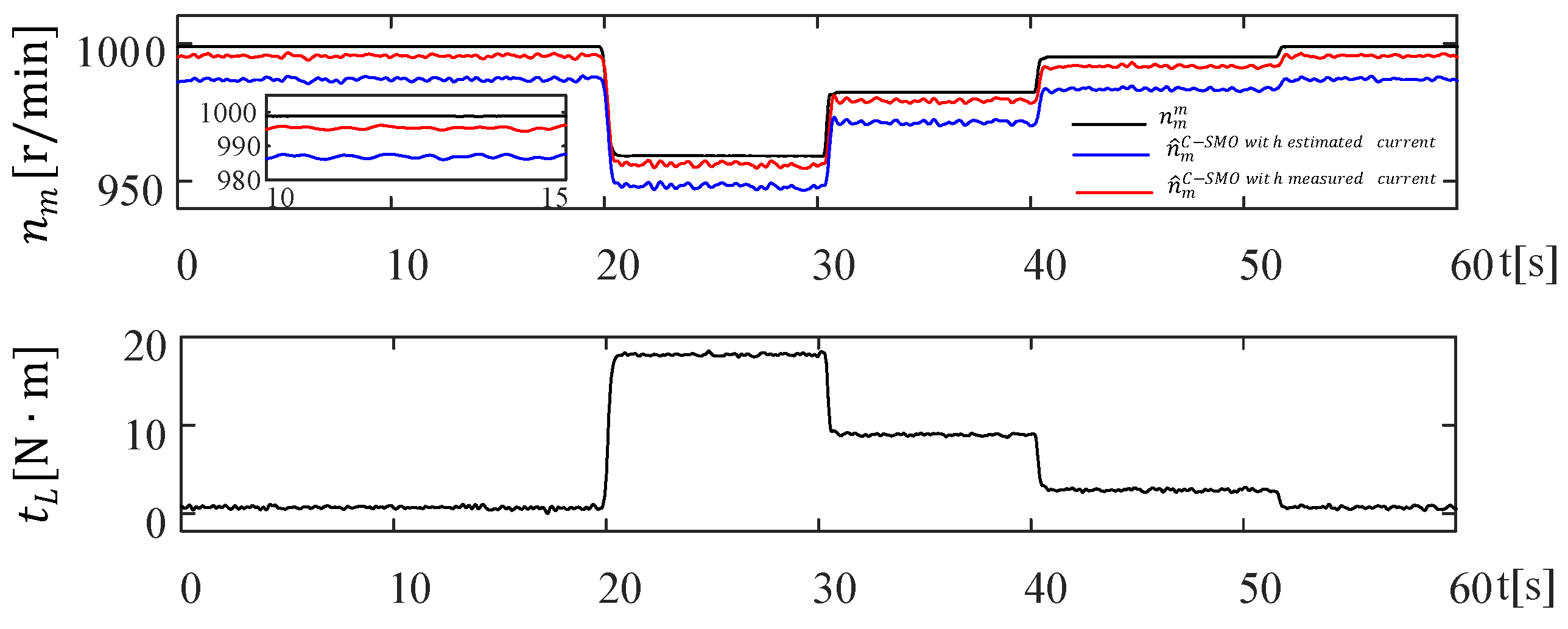
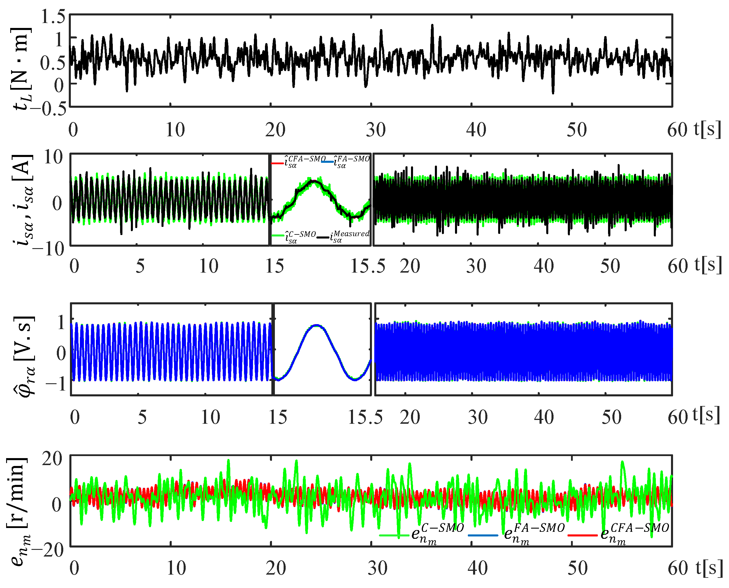
4.1. Scenario I: Usage of Measured Currents and Estimated Currents (Figure 9)
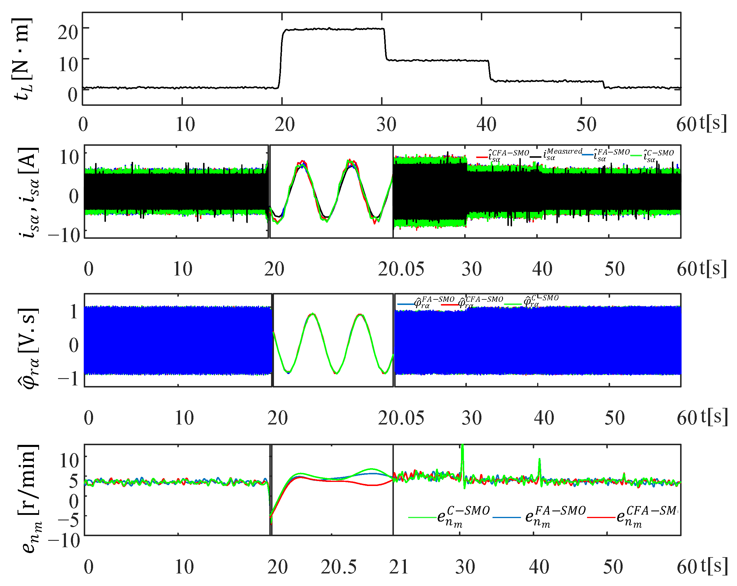
Scenario I tests the estimation performance of the measured stator currents of IM and the estimated currents of SMO in the case of sudden
variations for the high-speed region. Thus, the aim is to validate the correctness of the measured currents, used in (20) instead of the estimated currents which present chattering free against unknown
inputs. The obtained results are presented in
Figure 9.
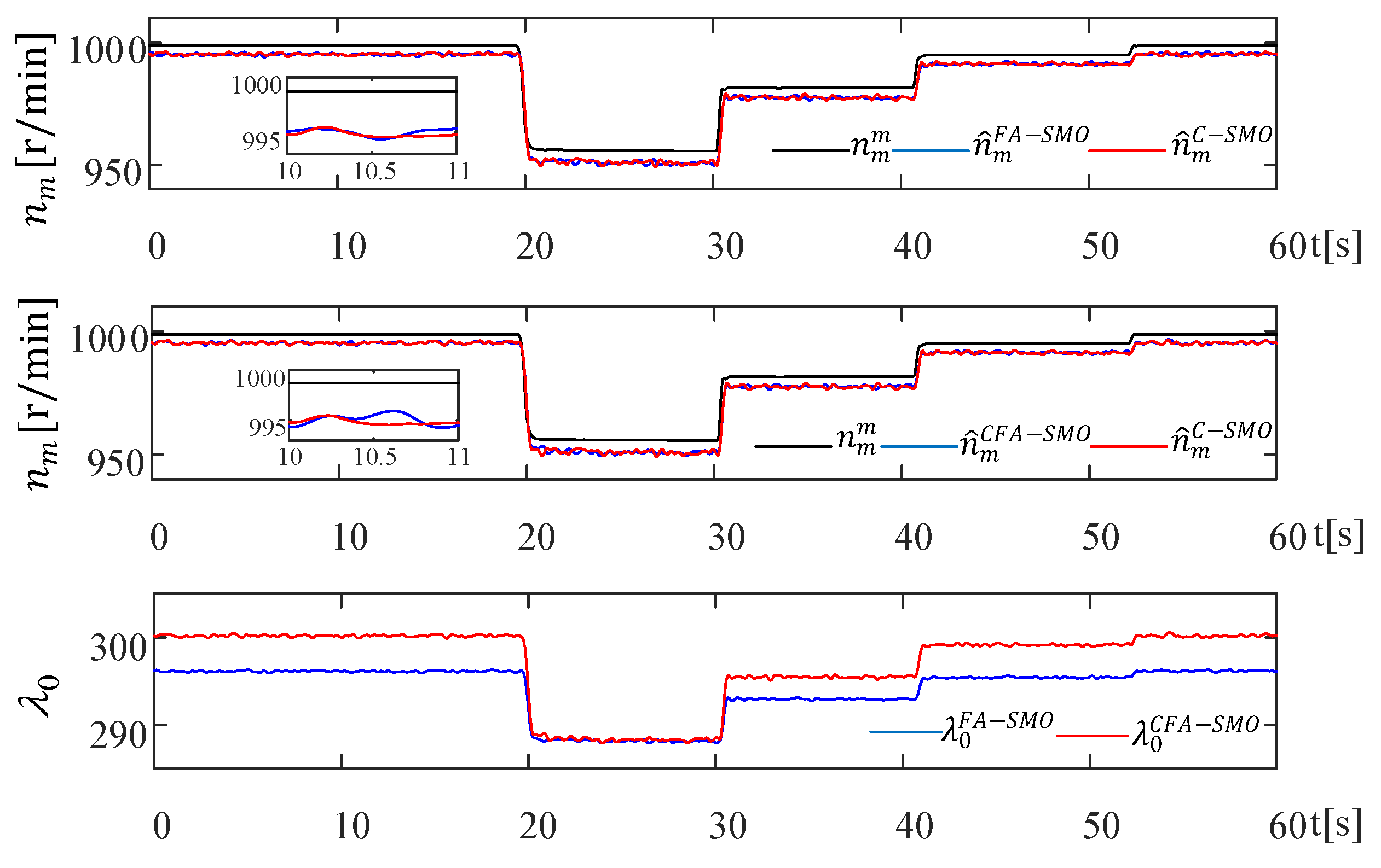
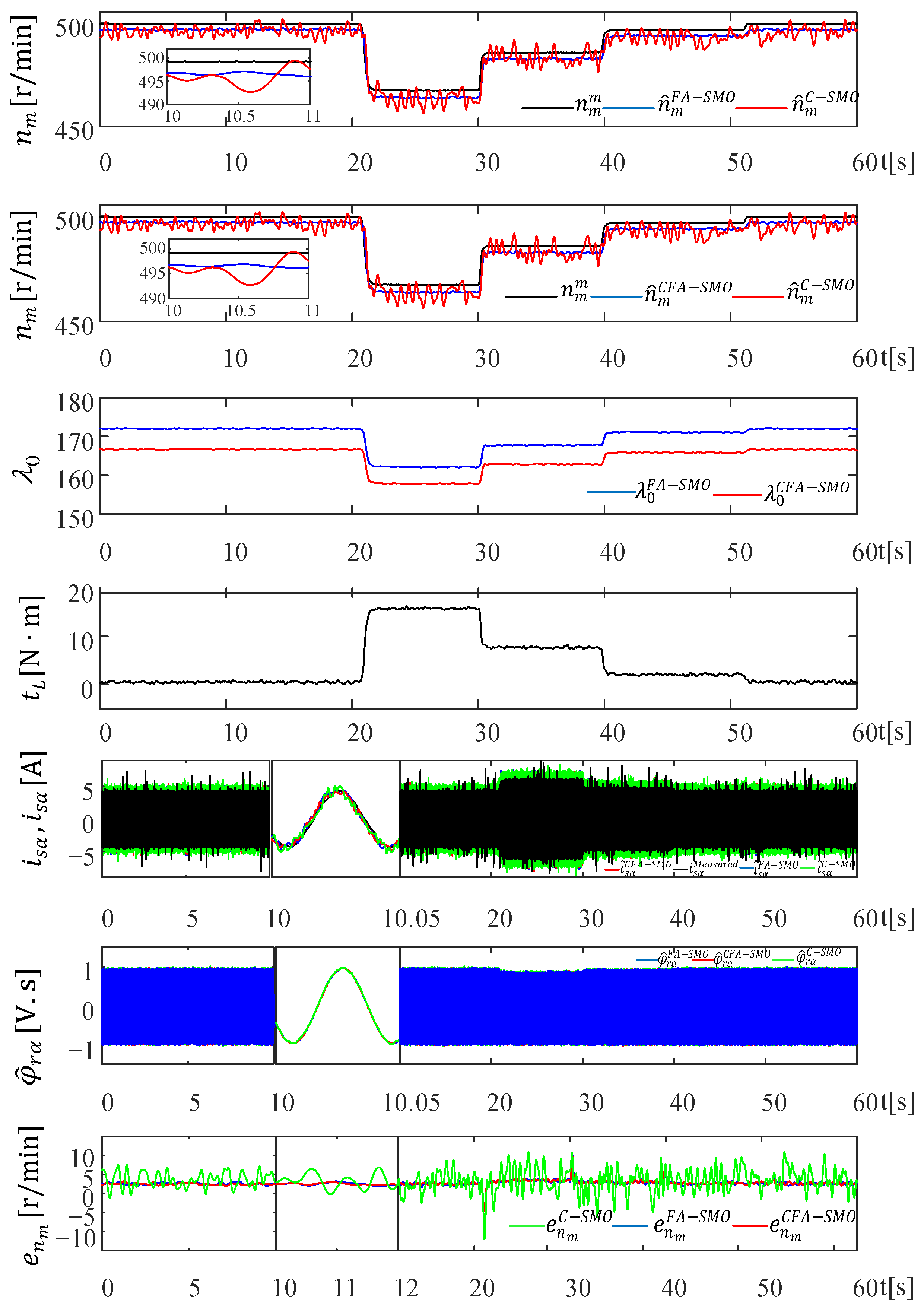
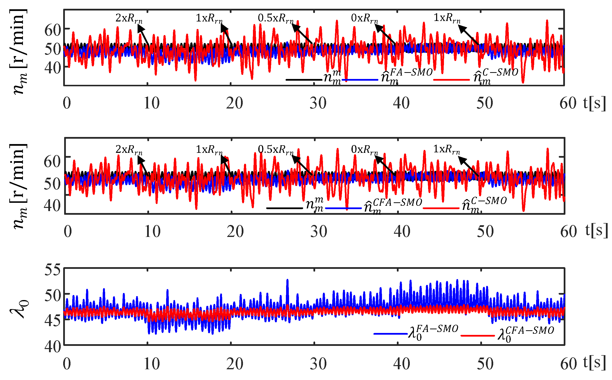
Scenario II tests the estimation performance of the proposed A-SMOs and C-SMO in the case of sudden
variations for three different speed regions, namely high, medium, and low speeds. Thus, the aim is to validate the robustness of the proposed A-SMOs against unknown
inputs. The estimation results and corresponding estimation errors are presented in
Figure 10,
Figure 11 and
Figure 12 for high, medium, and low speeds, respectively. In all tests shown in
Figure 10,
Figure 11 and
Figure 12, it is also possible to see the changes of
in A-SMOs and their favorable effects on
estimation by particularly inspecting
.
4.3. Scenario III: Speed-Reversal Test (Figure 13)
IM runs at its rated speed at no-load. After a sudden increase in load torque from no-load to rated load at approximately t = 40 s, the speed reversal is repeated at around t = 50 s. In this scenario demonstrated in
Figure 13, the performance of the proposed A-SMO observers is intended to be tested in a wide range of speed ranges, including the nominal speed for each rotation direction. Additionally,
values calculated by A-SMOs and the Lyapunov stability criterion are compared in this scenario.
4.4. Scenario IV: Sensitivity Tests on Parameters (Figure 14, Figure 15 and Figure 16)
To examine the effects of parameter variations on the proposed A-SMOs, first of all an
-change test is performed in the low-speed region, where the
variation is more effective due to the relatively high voltage drop ratio on
. Later, the
-change is also examined in the low-speed operation, similar to
-change while
-change is performed in the high-speed operation. For this purpose, the
changes are performed as in
Figure 14 through the group resistors connected in series to the stator terminals of IM. Since a squirrel cage IM is used in the experimental setup, it is not possible to change
by externally adding a group of series resistors. Therefore, to perform
variations in
Figure 15, the applied
is defined as
=
*
in the A-SMOs and C-SMO algorithms, and the variations in
are generated by changing
from 0 to 2. Similarly, the applied
is defined as
=
*
in the A-SMOs and C-SMO algorithms, and thus variations in
at high-speed operation as in
Figure 16 are developed by varying
from 0.5 to 2. Here,
and
are the rated values of
and
, respectively.
and
represent uncertainties related to
and
, respectively. Thus, it is possible to compare the performance of the proposed A-SMOs with C-SMO under parameter variations.
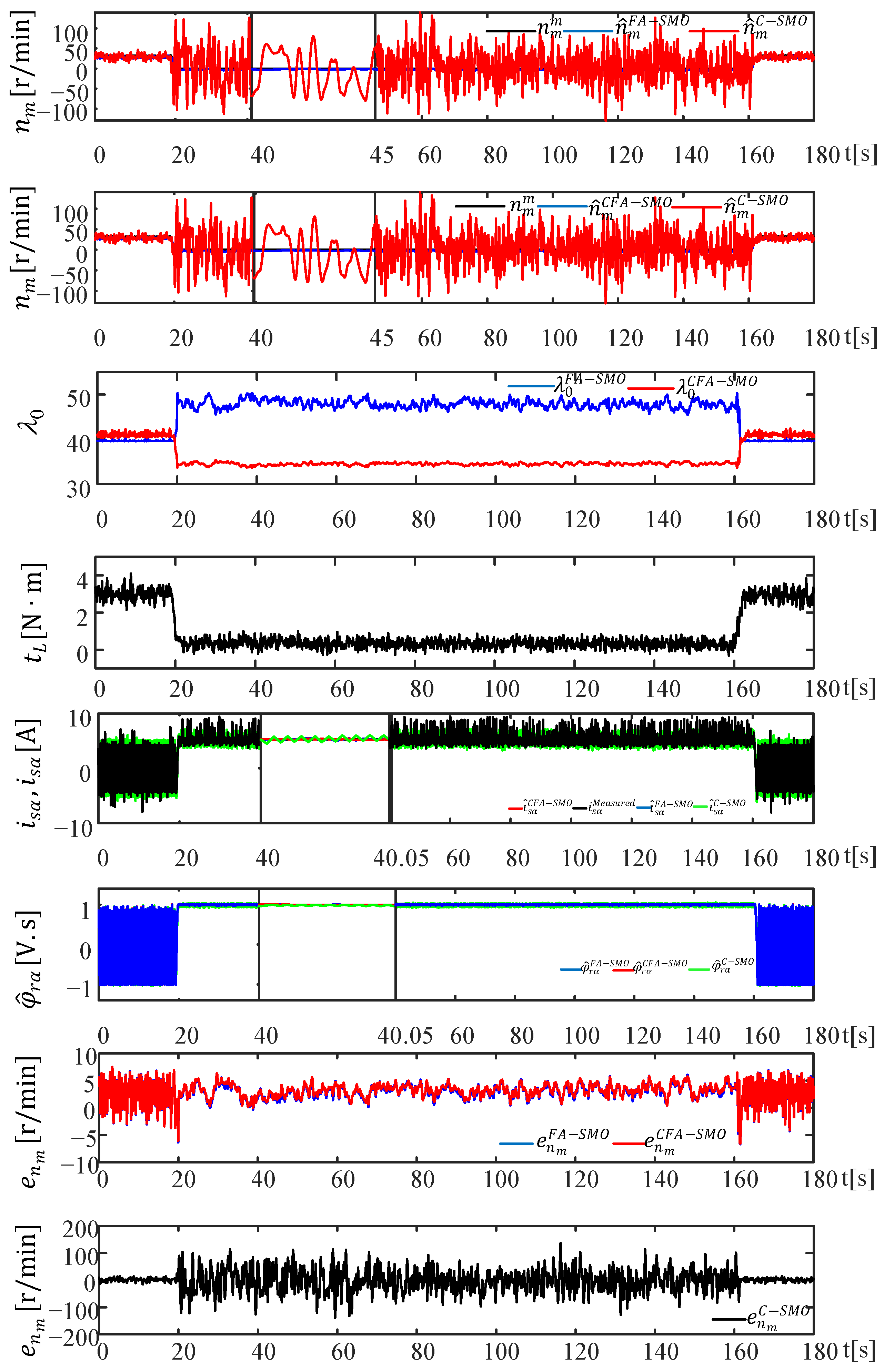
4.5. Scenario V: Continuous Zero Speed Test (Figure 17)
To test the estimation performance of the proposed A-SMOs in the case of continuous zero speed operation, the IM speed is decreased to zero while it is operating in the low-speed region without load as shown in
Figure 17. The results confirm that the estimation performance of the proposed observers is still satisfactory and the estimations do not diverge despite the fact that IM is continuously operating at zero speed.
Finally, the resulting mean square error (MSE), root mean square error (RMSE), and integral absolute error (IAE) values for estimations associated with each scenario are presented in
Table 3,
Table 4 and
Table 5, respectively. The total harmonic distortion (THD) of the estimated
-axis current for the proposed A-SMOs and C-SMO is given in
Table 6. The execution times for each observer obtained by calculating the average value for each iteration are given in
Table 7. When the real-time test results given in
Figure 9,
Figure 10,
Figure 11,
Figure 12,
Figure 13,
Figure 14,
Figure 15,
Figure 16 and
Figure 17 are examined, the following observations can be made:
