Abstract
Gas reservoir-type underground gas storage (UGS) plays a critical role in China’s natural gas reserves and peak shaving, serving as an essential component of the energy security system. Its unique cyclic injection and production operations not only stabilize the natural gas supply but also impose stringent requirements on the safety and integrity of geological structures, wellbores, and surface facilities. Weaknesses in current practices can cause accidents, directly threatening energy security. Therefore, continuously improving integrity management is the key to mitigating energy risks. Currently, the integrity management of gas storage faces challenges such as an abundance of standards and the complexity of management elements, which affect both operational safety and management efficiency. To address these issues, this study systematically analyzes domestic and international standards related to gas storage and establishes a technical system based on “three-in-one” integrity management (geological structure, wellbore, and surface facilities). Key elements of integrity management are identified and optimized, and recommended execution standards for critical factors are proposed to provide a theoretical basis and decision-making support for the safe operation of gas storage. This study not only offers a reference for optimizing and implementing integrity management standards but also has significant practical implications for enhancing energy security and reducing energy risks, ensuring the smooth execution of China’s natural gas reserve and peak shaving initiatives.
1. Introduction
Under the growing influence of the “low-carbon economy”, global demand for natural gas has been steadily rising, positioning the natural gas industry as a cornerstone of the energy sector. UGS, as a vital tool for natural gas supply and peak shaving, has emerged as a strategic infrastructure with significant advantages such as large storage capacity, flexible adjustment capability, and relatively low cost [1]. These attributes make it indispensable for balancing seasonal fluctuations in natural gas demand and ensuring secure energy supply. However, despite years of operation in China, the development of underground gas storage remains relatively nascent compared to actual demand and international standards. Particularly against the backdrop of growing peak shaving requirements, accelerating the construction and technological advancement of gas storage facilities has become a crucial strategic initiative to ensure a stable energy supply [2].
The safe operation of underground gas storage facilities is highly dependent on the geological conditions of the storage area, the structural integrity of the wellbore, and the reliability of surface facilities. The wellbore, serving as a critical conduit connecting the underground storage zone and surface infrastructure, poses considerable risks if its integrity is compromised. Failure of the wellbore can lead to natural gas leakage to the surface, which presents imminent threats to life and property and potentially causes irreversible environmental damage. For example, the Aliso Canyon gas storage facility incident resulted in massive methane emissions, becoming the second-largest methane leak in US history and severely impacting public health and the environment [3]. Similarly, the Brenham gas storage facility accident, caused by improper wellbore sealing, led to extensive natural gas leakage, with the gas accumulating in nearby groundwater layers and eventually diffusing through the soil to the surface. This incident triggered a large-scale explosion, causing three fatalities and the destruction of dozens of buildings. Consequently, timely prediction and identification of potential failures in the geological body, wellbore, and surface facilities of gas storage systems, coupled with timely and effective preventive measures, are critical for ensuring operational safety [4].
The integrity management UGS spans all phases of its lifecycle, including design, construction, operation, and decommissioning. Neglecting integrity management at any stage can lead to severe accidents. Over more than 20 years of development, China has made significant achievements in gas storage integrity management, establishing a comprehensive system of standards and technical advancements. However, despite these advancements, the standards for the “three-in-one” integrity management system for gas storage facilities are still incomplete. Specifically, the integrity requirements for geological bodies, wellbores, and surface facilities have not been fully defined, and the enforcement of these standards lacks consistency. To maximize the safety and operational efficiency of gas storage facilities, further refinement and optimization of the integrity management system are needed. These improvements will help prevent natural gas leakage incidents, ensure public safety and environmental protection, contribute significantly to the sustainable development of energy infrastructure, enhance China’s energy security, and raise the management standards for gas storage facilities [5].
This study systematically reviews domestic and international technical standards and practices related to underground gas storage (UGS), focusing on analyzing key elements of integrity management. To address critical risks and technical challenges, a “three-in-one” framework is presented, encompassing geological structures, wellbores, and surface facilities. By identifying specific management measures and standards, this study provides practical recommendations for optimizing UGS integrity management systems and improving the safety and reliability of gas storage operations. These findings offer theoretical foundations and actionable guidance, supporting the advancement of national energy security and implementing enhanced management practices effectively.
2. Review of Standards Related to UGS Integrity
2.1. Foreign UGS Related Standards
In the United States, the standards for underground gas storage primarily focus on three key regulations. First, API RP 1114-2013 provides comprehensive guidance for designing and constructing new salt cavern gas storage facilities. This standard covers various aspects, including site selection, cavern creation, testing, and commissioning, to ensure construction quality and operational safety. Second, API RP 1115-2012 serves as a fundamental guide for operating salt cavern gas storage facilities. However, this standard is primarily intended for storing liquid hydrocarbons or liquefied petroleum gas (LPG) and does not fully address the requirements for natural gas storage. Finally, API RP 1171-2022 offers recommendations for the functional integrity of two types of gas storage facilities. These recommendations encompass construction, maintenance, operation, risk management, and integrity management procedures, aiming to ensure functional integrity throughout the entire lifecycle of the storage facilities underground. Gas storage is primarily covered by the CSA Z341 Series-2018. This series of standards establishes the minimum requirements for various types of underground gas storage facilities across different phases, including design, construction, operation, maintenance, decommissioning, and safety. These standards ensure that gas storage facilities meet essential safety and quality benchmarks throughout their entire lifecycle.
In the European Union, standards for underground gas storage are primarily defined by the EN 1918:2016 series. This series outlines recommended practices for the full lifecycle of gas storage facilities and is divided into five parts—Recommended Practices for Storage in Aquifers, Recommended Practices for Storage in Depleted Hydrocarbon Reservoirs, Recommended Practices for Storage in Salt Caverns, Recommended Practices for Storage in Mines, and Recommended Practices for Surface Facilities Associated with Gas Storage. These standards provide general principles for the design, construction, testing and commissioning, operation, monitoring, maintenance, and decommissioning of various types of gas storage facilities, ensuring safety and reliability throughout their lifecycle.
Standards for UGS abroad typically address risk identification across three levels—geological bodies, wellbores, and surface facilities—reflecting the “three-in-one” risk management concept. These standards are generally presented as recommended practices and extensively reference other related standards. Their strengths lie in their comprehensive scope, strong, principled guidance, and the provision of overarching requirements for various lifecycle stages. However, these standards also have certain limitations, such as the lack of detailed professional subdivisions and specialized, refined standards. This can result in challenges related to specificity and practicality during their implementation.
2.2. Current Status of Standard Construction of UGS in China
As of 2023, China has 33 operational UGS facilities, with a total design working gas capacity of 34.5 billion cubic meters. Among these, 29 are gas reservoir-type storages, accounting for 88%, and four are salt cavern-type storages. The peak shaving capacity of these UGS facilities has reached 23 billion cubic meters, with a maximum daily peak shaving capacity of 260 million cubic meters. These UGS facilities play a critical role in ensuring national energy security, particularly in managing seasonal fluctuations in natural gas demand. During peak periods, such as the winter heating season, UGS facilities provide a stable peak shaving capacity, ensuring the reliability of the natural gas supply. This makes them indispensable for the smooth operation of the national energy supply system and for meeting the essential energy needs of the public.
Compared to the century-long history of UGS development abroad, the construction of gas reservoir-type underground gas storage in China started relatively late. Moreover, domestic projects face significant challenges, such as complex geological conditions, great burial depths, and poor reservoir properties, all of which considerably increase construction difficulty and investment costs. Additionally, the applicability of foreign supporting technical standards in the domestic context is somewhat limited.
Since 2006, China has begun issuing technical standards for gas storage facilities. To date, 98 related standards have been published, including two national standards, 45 industry standards, and 51 corporate standards developed by China National Petroleum Corporation (CNPC). Based on the operational stages of gas storage facilities, 32 standards apply to the construction phase, while 66 standards cover the operational phase. From a professional perspective, 16 standards focus on geological reservoirs, 42 address injection and withdrawal engineering, 34 pertain to surface engineering, and six deal with quality, safety, and environmental protection. These standards broadly cover all specialties and aspects of the gas storage construction business chain. However, a complete and systematic standard framework has yet to be established.
2.3. Comparative Analysis of UGS Standards in China and Abroad
The development and implementation of technical standards play a critical role in ensuring the safety, reliability, and efficiency of underground gas storage (UGS) facilities. This section provides a comparative analysis of prominent UGS standards from the United States (API RP 1171), Canada (CSA Z341), and China (SY/T series standards), highlighting key differences in their scope, focus, and applicability. Based on this analysis, recommendations are proposed to integrate best practices from international standards into China’s regulatory framework, making it more robust and comprehensive.
2.3.1. Key Differences
A key distinction between the standards lies in their approach to lifecycle management. Both API RP 1171 and CSA Z341 adopt a holistic approach that addresses UGS integrity across all stages, including planning, design, operation, and decommissioning. This comprehensive coverage ensures that potential risks are managed throughout the lifecycle of the facility. In contrast, the SY/T series standards primarily focus on engineering design and construction phases, providing limited guidance for operational risk management or decommissioning activities. Such a narrow scope underscores the need for a broader lifecycle-oriented framework within Chinese standards.
Another significant difference is the emphasis on risk-based approaches. API RP 1171 and CSA Z341 prioritize risk-based inspection (RBI) and decision-making frameworks, offering detailed methodologies for identifying, evaluating, and mitigating risks throughout the facility’s lifecycle. These frameworks enable adaptive management strategies that respond to emerging challenges. Conversely, the SY/T standards rely heavily on prescriptive measures, lacking the robust methodologies needed for proactive risk management. This limitation constrains the ability to address dynamic operational risks effectively.
The integration of advanced technologies is another area where international standards demonstrate superiority. Both API RP 1171 and CSA Z341 encourage the adoption of data-driven monitoring systems, digital twin models, and predictive analytics to enhance operational safety and efficiency. These innovations support real-time decision-making and improve the accuracy of integrity assessments. Chinese standards, however, remain centered on traditional engineering solutions and have yet to incorporate such technological advancements, limiting their effectiveness in modern UGS management.
Environmental and community considerations also mark a notable difference. API RP 1171 includes explicit guidelines for environmental protection and community engagement, reflecting a broader commitment to sustainability. Similarly, CSA Z341 addresses these concerns by outlining measures to minimize environmental impact and ensure community safety. In contrast, the SY/T standards are primarily technical in nature, offering little guidance on environmental or social dimensions. This gap highlights the need for a more inclusive approach to UGS management in China.
2.3.2. Recommendations for China’s Standards
To enhance the robustness and applicability of China’s UGS standards, it is imperative to integrate the strengths of international frameworks. A critical step is the adoption of risk-based approaches, as demonstrated by API RP 1171 and CSA Z341. These methodologies emphasize lifecycle risk management and enable facilities to identify and mitigate potential hazards effectively. By developing frameworks for regular risk assessments during the operational phase and implementing RBI strategies, Chinese standards can prioritize resources for high-risk components and improve overall safety.
Incorporating advanced technologies is another essential recommendation. Real-time monitoring systems, IoT-based data collection, and predictive analytics should be actively encouraged to enhance the accuracy and efficiency of integrity assessments. Additionally, the use of digital twins to simulate and optimize UGS operations can provide significant benefits by enabling proactive management of complex systems. Developing specific guidelines for the integration of such technologies would ensure their effective application within Chinese standards.
Broadening the environmental and social provisions within the SY/T standards is equally important. Explicit guidelines should be included to minimize environmental impacts and actively engage with local communities. Establishing protocols for emergency response and environmental remediation in the event of UGS failures would further strengthen the standards. Such measures would align China’s standards with global sustainability practices and address growing societal expectations for responsible energy management.
Finally, enhancing international collaboration is essential to modernize China’s UGS standards. Collaborating with international organizations to harmonize standards and adopt best practices would facilitate knowledge exchange and the incorporation of global advancements in UGS integrity management. Such efforts would ensure that Chinese standards remain competitive and adaptable to evolving industry challenges.
2.3.3. Conclusions
This comparative analysis underscores the pressing need for China’s UGS standards to evolve from a predominantly technical focus to a more comprehensive, risk-based, and lifecycle-oriented framework. By integrating the holistic approaches of API RP 1171 and CSA Z341, Chinese standards can address the complexities of modern UGS operations more effectively. These improvements would not only enhance safety, reliability, and sustainability but also contribute significantly to strengthening national energy security.
3. UGS Integrity Management
3.1. Geological Reservoir Integrity Management
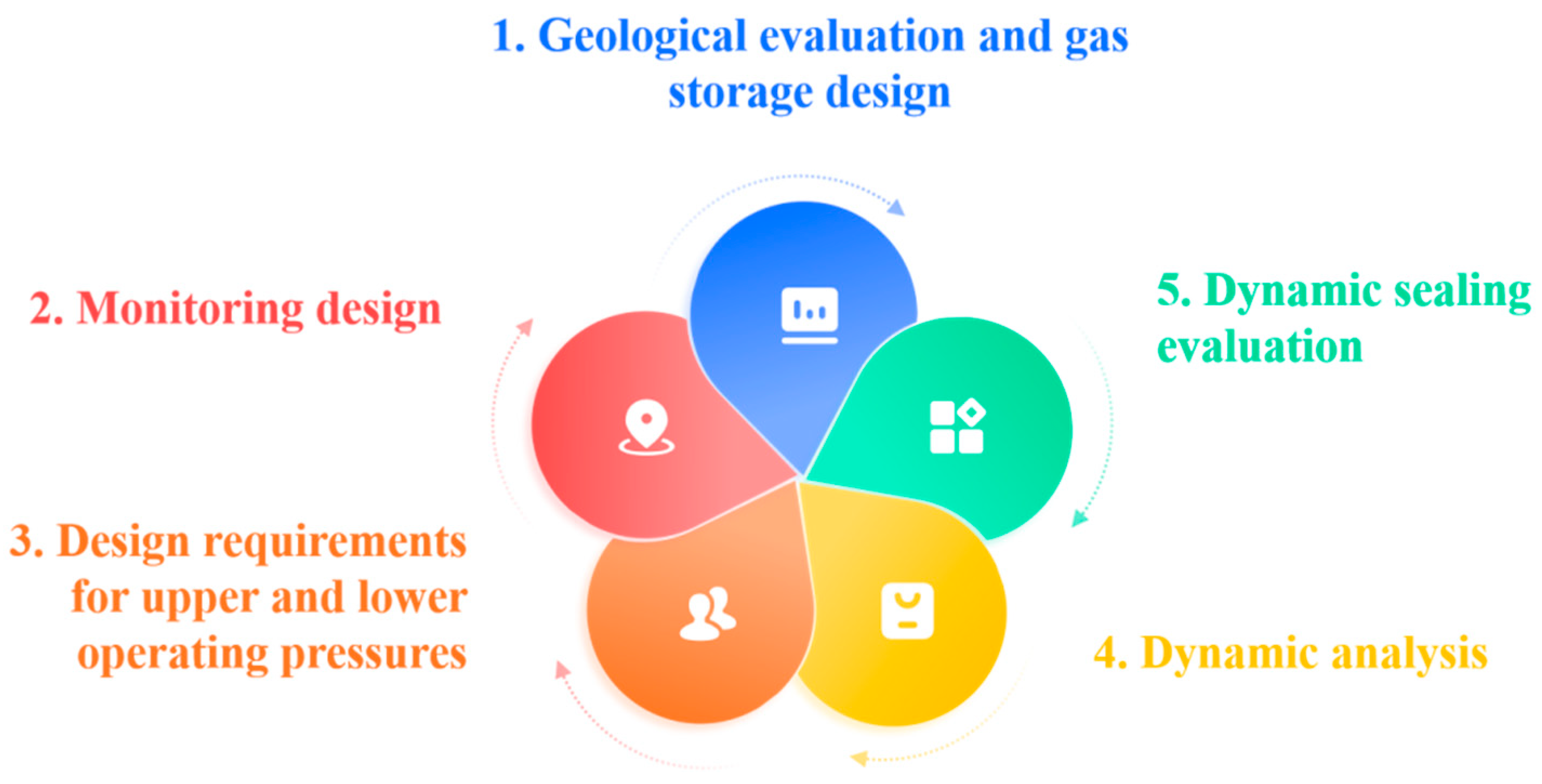
In the research and application of geological reservoir integrity for UGS, the systematic analysis and summarization have subdivided the key elements into five aspects—geological evaluation and gas storage design, monitoring design, design requirements for upper and lower operating pressures, dynamic analysis, and dynamic sealing evaluation—as shown in Figure 1.
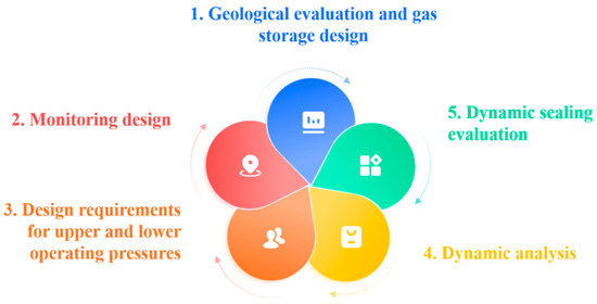
Figure 1.
Key elements of geological reservoir integrity management in UGS.
The standard requirements for these elements are derived from various industry technical specifications and codes, such as the SY/T 6805, SY/T 6848, and SY/T 7652. The specific requirements and standard references for each key element are detailed below.
Geological Evaluation and Gas Storage Design: In the geological evaluation and gas storage design of UGS facilities, key factors include the structural morphology of the geological body, fault distribution, caprock sealing capacity, and reservoir fluid characteristics. According to standards such as SY/T 6805 and Q/SY 01636, the evaluation of the geological body should encompass structural features, fluid distribution, and the sealing capacity of the caprock and boundary faults. Based on these evaluation results, the gas storage design should determine operational pressure parameters, storage capacity parameters, and the design of injection-production formations and well networks, ensuring the long-term safety and efficient operation of the UGS [6].
Monitoring Design: The monitoring design for UGS is critical to ensuring safety throughout its lifecycle. Monitoring should include formation pressure, caprock sealing integrity, fault sealing capacity, gas flow, as well as temperature and pressure field surveillance. According to Q/SY 01636, continuous monitoring of the temperature field, pressure field, fluid field, and wellbore conditions is required. Particular emphasis should be placed on observing lithological changes in the caprock and monitoring the pressure and fluid states in fault-developed areas to ensure a real-time understanding of the operational status of the UGS. Additionally, continuous monitoring of reservoir pressure and fracture propagation is essential to assess the sealing capacity of the reservoir. Advanced technologies such as microseismic surveys and real-time stress field analysis can be applied to track the long-term integrity of the geological body, providing dynamic assessments of potential leakage risks.
Design Requirements for Upper and Lower Operating Pressures: The design of upper and lower operating pressures is a critical safety control factor for the operation of UGS [7]. According to standards SY/T 6805 and SY/T 7652, the upper pressure should generally not exceed the original formation pressure of the gas reservoir. However, after thorough evaluation and safety verification, it may be increased to 1.2 times the hydrostatic pressure of the reservoir. The design of the lower pressure should take into account the minimum peak-shaving capacity at the end of the withdrawal phase, the minimum production capacity of individual wells, and the prevention of edge or bottom water interference with gas well productivity. This ensures the economic viability and safety of the UGS operation, even during the late stages of its lifecycle [8].
Dynamic Analysis: Dynamic analysis of UGS is primarily used to evaluate pressure variations, fluid distribution, and changes in injection and withdrawal capacity during operation. According to SY/T 7649, the dynamic analysis should include a comprehensive assessment of reservoir characteristics, injection and withdrawal capacity, inventory levels, and displacement efficiency. In particular, analyzing inventory characteristics, gas-liquid interface variations, and dynamic changes in production capacity provides critical insights for optimizing peak-shaving capabilities and operational efficiency [9].
Dynamic Sealing Evaluation: Dynamic sealing evaluation is critical for ensuring the stability of the UGS geological body during multicycle injection and withdrawal operations [10]. The standard SY/T 7761-2024 specifies the content of sealing evaluations, including monitoring pressure and fluid behavior in caprock, faults, and spill points, combined with microseismic and geostress analyses to assess the sealing capacity of the UGS. The dynamic analysis of monitoring data—covering parameters such as breakthrough pressure, slip tendency index, and permeability—provides a basis for sealing management of the UGS.
This study systematically analyzes five key elements of integrity management in UGS, clarifying their specific requirements. First, geological evaluation and gas storage design should encompass structural features, fault distribution, and caprock sealing capacity, with operational pressure and storage capacity design optimized based on these evaluations. Second, the monitoring design must ensure continuous surveillance of critical parameters such as formation pressure, temperature fields, and fluid fields to guarantee the safe operation of the UGS. Third, the design of upper and lower pressure limits must comply with standard requirements, ensuring both economic viability and safety during the late stages of operation. Fourth, dynamic analysis evaluates pressure variations and injection/withdrawal capacity, supporting the optimization of peak-shaving capabilities. Finally, dynamic sealing evaluation ensures stability during multicycle injection and withdrawal by monitoring caprock and fault conditions. These requirements provide essential technical support for the lifecycle management of UGS, enhancing its safety and operational efficiency [11].
3.2. Well Integrity Management
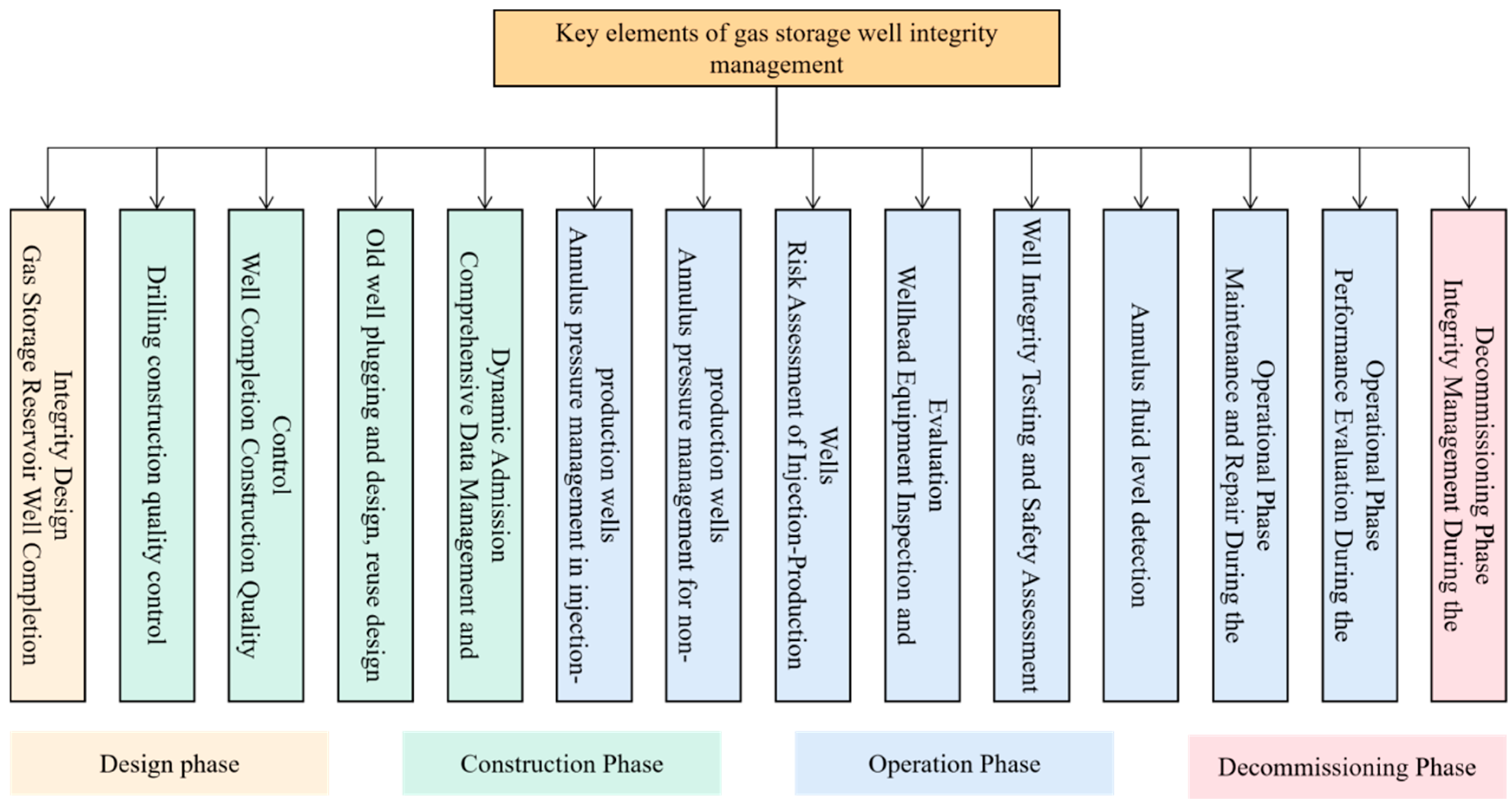
Well integrity management in UGS encompasses lifecycle integrity management, covering the design, construction, operation, and decommissioning phases. Based on the characteristics and practical applications of UGS well integrity and through the research and analysis of relevant standards, 14 key elements of well integrity management have been identified. The specific classifications are shown in Figure 2.
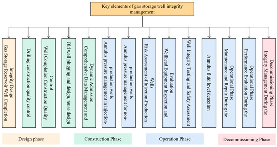
Figure 2.
Key elements of well integrity management.
3.2.1. Drilling and Completion Integrity Design
The drilling and completion integrity design for UGS involves benchmarking analysis across multiple domains, including well type, wellbore trajectory, well structure design, drilling fluid design, casing string design, cementing design, and completion design. Periodic inspections using acoustic and electromagnetic testing methods are critical to evaluate casing strength, cement sheath integrity, and sealing capacity. These methods provide accurate assessments of the wellbore’s structural integrity, helping to identify potential issues such as casing wear, cement sheath degradation, or seal failures.
Operations during drilling or fracturing processes, such as the behavior of fracturing fluid transport and wellbore pressure control methods, can influence the parameters of the gas storage facility, particularly during the fracturing or wellbore repair of the reservoir [12]. These operations may lead to changes in the physical properties of the reservoir, affecting both the storage capacity and safety of the underground gas storage. Related studies have shown that the transport mechanisms of fracturing fluids and variations in downhole operations significantly impact the long-term stability of the gas storage facility [13]. In addition, during the design phase, specific attention is given to the geological conditions and reservoir characteristics to ensure the integrity of the wellbore throughout its lifecycle.
According to Q/SY 01561-2019 and SY/T 6805-2017, the selection of well types for UGS must comply with stringent standards. Specifically, SY/T 6805-2017 highlights the importance of adopting cluster well group layouts. Regarding wellbore trajectory, both Q/SY 01561-2019 and SY/T 5435 specify methods for directional well trajectory design. Q/SY 01561-2019 further stresses that wellbore trajectories must not only comply with the provisions of SY/T 5435 but also ensure a minimum distance of 10 m between adjacent wellheads in a cluster well group. Additionally, the design of new wells must account for measurement errors in the trajectories of existing wells. For well structure design, both Q/SY 01561-2019 and SY/T 5431 outline specific requirements. Q/SY 01561-2019 expands upon SY/T 5431 with four additional requirements, as follows: (i) the well structure of injection/withdrawal wells must accommodate high-intensity injection/withdrawal, long service life, and cyclic load variations; (ii) dedicated reservoir drilling technology must be employed; (iii) casing depths should be designed based on actual formation pore pressure, collapse pressure, and fracture pressure data; (iv) the production casing size must be determined according to injection and withdrawal demands, ensuring that the annular space satisfies the long-term sealing requirements of the cement sheath. These requirements provide comprehensive and normative guidance for the structural design of UGS wells.
Drilling fluid design requirements are outlined in four standards—Q/SY 01561-2019, SY/T 7377, SY/T 6805-2017, and SY/T 7648-2021. Building upon the foundation of SY/T 7377, Q/SY 01561-2019 introduces two specific requirements for drilling fluid design in UGS: (i) the reservoir section must use a drilling fluid system that effectively protects the reservoir, and (ii) drilling operations in the reservoir section should reasonably set key parameters such as drilling fluid density based on actual formation pressure. Similarly, SY/T 6805-2017 aligns closely with the provisions of Q/SY 01561-2019, explicitly stating that drilling fluid design must satisfy technical requirements for preventing losses, wellbore collapse, and blowouts, as well as ensuring reservoir protection [14].
In the design of casing strength for UGS, the impact of long-term cyclic stress variations must be considered. The design of casing strings should comply with four standards—Q/SY 01561-2019, SY/T 7451-2021, SY/T 6805-2017, and SY/T 7648-2021. By integrating these standards, casing string design must first meet the strength verification requirements for surface and intermediate casings as specified in SY/T 5724. Additionally, the design must adhere to the five requirements outlined in Table 1.

Table 1.
UGS casing strength design requirements.
In the field of cementing design, cementing technology plays a crucial role in isolating oil, gas, and water layers within wells, protecting casings, enhancing the durability of gas wells, and extending their service life.
Cementing design must adhere to four key standards—Q/SY 01561-2019, SY/T 7451-2021, SY/T 6805-2017, and SY/T 7648-2021. These standards emphasize the importance of considering the potential impacts of long-term high-intensity injection and withdrawal activities and cyclic stress on cement sheath integrity during cementing design. They also require that cement slurry in each casing layer must be returned to the surface [15].
Regarding cement systems, Q/SY 01561-2019 recommends using a toughened cement system. SY/T 7451-2021 specifies that for wells with low pressure-bearing capacity in the bottom layer and long sealing sections, a low-density, high-strength cement slurry system should be used. It further stipulates that the density of the cement slurry should be 0.1 g/cm3 to 2 g/cm3 higher than that of the drilling fluid used in the same well. SY/T 7648-2021 suggests the use of an elastic-toughened cement slurry system for the production casing and caprock segments. For cementing sections with low formation pressure capacity, it recommends low-density cement slurry systems, with the production casing and caprock ends requiring low-density elastic-toughened cement slurry. Although these standards vary slightly in specific requirements, their overall guidelines are similar and can be applied in combination.
In the well completion design process, ensuring smooth fluid flow is critical. The design must evaluate potential threats to wellbore safety posed by high-temperature, high-pressure environments, and acidic production fluids. Attention must also be given to potential tubing blockages caused by asphaltene deposition, formation damage from solid particle blockages, and the erosion of production tubing and wellheads by solid particles.
To ensure well completion safety, the following measures can be implemented: (i) install packers, use high-pressure-resistant wellheads and production trees, and deploy corrosion-resistant alloy casing and tubing. Corrosion inhibitors should be injected to protect the wellbore; (ii) asphaltene removers, along with associated pipelines and valves, should be used to remove deposited asphaltene; (iii) control production pressure differentials to prevent solid particle production and install sand control screens to stop solid particles from entering the production tubing and causing erosion; (iv) install solid-phase production monitoring equipment to track solid output and take measures to protect the choke.
In the design of tubing strings and downhole tools for completion, applicable standards include SY/T 6805-2017, Q/SY 01012-2017, and SY/T 7370-2017. These standards specify requirements for gas-tight threaded tubing connections, completion string separators, downhole safety valves, casing protective fluids in the annular space between the casing and production tubing, tubing size, anticorrosion materials, and strength verification. Particularly, SY/T 7370-2017, focusing on completion design for UGS operational conditions, recommends the use of gas-tight threaded joints for tubing connections, which must remain leak-free after 30 full-size gas-tight cycles. Q/SY 01012-2017 provides specific requirements for wellhead assemblies, safety control system design, and annular protective fluids. For wellhead assemblies, it stipulates pressure and temperature ratings and specifies the installation positions for production trees, wellhead safety valves, and pressure gauges.
3.2.2. Drilling Construction Quality Control
The key to quality supervision in drilling operations lies in establishing a comprehensive quality management system and optimizing various quality control processes. This includes stringent oversight of wellbore structure, quality control of coring processes, and quality management of cementing operations. Specifically, the standards mandate onsite thread gas-tightness testing for technical casing in the cap rock section and production casing, with the test pressure exceeding 1.1 times the maximum operating pressure of the UGS. According to SY/T 6805─2017 and SY/T 7451─2021, the requirements for thread gas-tightness testing of casing include the inspection of each casing individually. The test pressure must not be less than 1.1 times the maximum operating pressure of the UGS and should not exceed 80% of the casing’s internal pressure resistance strength.
3.2.3. Well Completion Construction Quality Control
In the field of well completion construction quality monitoring for cementing quality control, relevant standards have clearly defined the requirements for cementing quality, waiting-on-cement (WOC) time, and cementing quality testing. The cementing quality standards specify that the bonded length of the cement sheath for production casing must reach at least 70%, with a minimum of 25 m of continuously high-quality cement above the reservoir in the cap rock section or an accumulated high-quality cement interval of at least 50 m. For WOC time, except for surface casing cementing, other cementing operations must have a WOC time of no less than 48 h, and for low-density cement slurry systems, the WOC time must not be less than 72 h. For cementing quality testing, sonic amplitude/variable density logging should be employed, with ultrasonic imaging logging additionally required for production casing and cap rock sections.
In terms of casing pressure testing, the pressure test value for production casing strings must not be less than 1.1 times the maximum operating pressure of the UGS injection-production well. The wellhead pressure must not exceed the rated pressure of the wellhead equipment. Both SY/T 7451-2021 and SY/T 7648-2021 stipulate that the pressure at any point of the casing string must not exceed 80% of the casing’s internal pressure resistance strength. When necessary, sectional pressure testing may be employed, with a pressure drop of no more than 0.5 MPa within 30 min considered acceptable.
3.2.4. Old Well Plugging and Design, Reuse Design
The design and reuse of abandoned wells are critical components in the construction of UGS, as the quality of well plugging directly impacts the safety and reliability of UGS operations. When plugging abandoned wells, the general principle of “enhancing formation plugging, preventing wellbore leakage, and implementing real-time pressure monitoring” should be followed. According to SY/T 6848-2012 and SY/T 6805-2017, explicit guidelines are provided for the plugging, design, and reuse of abandoned wells.
For abandoned well plugging design, the plugging materials must withstand the long-term high pressures and cyclic stresses typical of UGS operations, ensuring permanent sealing. Performance standards for these materials are specified through laboratory testing, detailing the required quantity of plugging agents and injection pressures. Additionally, the standards provide detailed specifications for plugging techniques and materials tailored to different storage reservoir sections.
Regarding the reuse of abandoned wells, the design requirements for converting them into monitoring or production wells are clearly outlined, including (i) cement sheath integrity: the cap rock section above the storage reservoir must have at least 25 m of continuous, high-quality cement sheath, with at least 70% of this section rated as good or higher; (ii) pressure testing of production casings: the production casing must undergo pressure testing using a water medium to the maximum operating pressure of the UGS, with a pressure drop of no more than 0.5 MPa within 30 min; and (iii) casing strength verification: the strength of the casing string must be verified based on measured casing wall thickness to ensure compliance with operational demands. These requirements ensure the safety and reliability of both the plugging and reuse processes, contributing to the effective construction and operation of UGS facilities [16].
3.2.5. Comprehensive Data Management and Dynamic Admission
The integrity data of UGS encompass a wide range of information, including geological, geophysical, seismic, logging, and dynamic monitoring data, which are crucial for evaluating the integrity of UGS facilities [9]. Effective management and dynamic recording of these integrity data involve the statistical analysis of the specifications for data requirements across the design, construction, and operation phases of UGS. These standards include SY/T 7633-2021, SY/T 6848-2012, Q/SY 01012-2017, Q/SY 01022-2018, and Q/SY 01183.2-2020. These standards provide comprehensive guidance for UGS data collection and management (Table 2).
Table 2.
UGS integrity data specification requirements.
3.2.6. Annulus Pressure Management in Injection-Production Wells
Management of annular pressure in injection-production wells involves monitoring, identifying, evaluating, and addressing pressure within the annular space between the casing and drill string. The annulus refers to the area between the casing and drill string inside the oil and gas well, with the pressure in this space defined as annular pressure. The primary objective of this management process is to ensure the safe operation of injection-production wells and prevent accidents caused by abnormal annular pressure. The management measures include (i) establishing a safe range for annular pressure in UGS injection-production wells; (ii) conducting real-time monitoring of annular pressure during injection-production operations; (iii) implementing pressure release and continued monitoring if the annular pressure exceeds the safe range; (iv) identifying pressure sources based on pressure variation; and (v) addressing annular pressure issues by performing pressure relief treatment and resuming production operations for UGS injection-production wells. It is recommended to follow Q/SY 01879-2021. However, this standard does not include requirements for diagnosing leakage locations and conducting hazard grading management based on pressure bleed-off and recovery tests. Detailed standard requirements are provided in Table 3.
Table 3.
Standard requirements for annular pressure management in injection-production wells.
3.2.7. Annulus Pressure Management for Non-Production Wells
Currently, the management of annular pressure for non-injection-production wells remains inadequate. The existing standards, SY/T 7651-2021 and Q/SY 01183.2-2020, only provide basic requirements for the routine operation and management of plugged wells but lack specific requirements and methodologies for tiered management. Implementing tiered assessments and risk control for non-injection-production wells can significantly benefit well integrity assurance. The classification criteria for non-injection-production wells are presented in Table 4.
Table 4.
Non-production and injection well classification criteria.
Based on the results of wellhead pressure tests, risk levels for non-injection-production wells can be assessed, and corresponding risk control measures can be adopted based on different risk levels. Detailed standards for risk classification and emergency response measures are provided in Table 5.
Table 5.
Non-production and injection well control measures.
3.2.8. Risk Assessment of Injection-Production Wells
The risk assessment of UGS injection-production wells aims to ensure the safe operation of surface facilities and wellbores. Typically, risk-based inspection (RBI) techniques are employed to evaluate the safety of UGS injection-production wells. According to SY/T 7651-2021, annual risk identification, assessment, and classification should be conducted, accompanied by the formulation of corresponding control measures.
Failure probability analysis is performed based on historical failure data and reliability evaluation models. Clear qualitative, semiquantitative, and quantitative methods for the risk assessment and classification of injection-production wells are proposed [17]. A comparative overview of specific standards is provided in Table 6.
Table 6.
Standard requirements for risk assessment field of injection and production wells.
3.2.9. Wellhead Equipment Inspection and Evaluation
In the field of wellhead equipment inspection and evaluation, Q/SY 1486-2012 was the first to specify the requirements for inspections and evaluations in the near-wellhead region. Subsequently, SY/T 7651-2021 and Q/SY 01183.2-2020 further refined the timing of initial inspections, the frequency of subsequent inspections, the scope of inspection items, and the specific inspection locations. These inspections encompass tasks such as visual inspection, wall thickness measurement, defect detection, and surface hardness testing. Notably, Q/SY 1486-2012 introduced seal integrity testing as a new inspection item, while the remaining requirements have largely remained unchanged. Q/SY 01873-2021 categorized wellhead equipment and classified UGS injection-production wells as Class I wells, mandating a maximum inspection interval of three years. This standard also explicitly defines inspection methods, data analysis, and handling requirements. It is recommended to adopt Q/SY 01873-2021 as the standard for wellhead equipment safety evaluation processes, with additional reference to the relevant requirements of Q/SY 1486-2012.
3.2.10. Well Integrity Testing and Safety Assessment
The primary objective of wellbore integrity evaluation is to identify integrity defects in critical components such as tubing, casing, cement sheath, and packers, while precisely locating and classifying these defects. This ensures a comprehensive understanding of the wellbore’s integrity status. Currently, integrity assessments for gas wells primarily rely on acoustic and electromagnetic-based technologies, which can accurately detect and locate issues such as tubing leaks, thread seal leaks, casing leaks, annular cement sheath micro-annuli, sub-liquid level leaks, and multiple concurrent leaks. In the field of wellbore integrity testing and safety evaluation, inspection tasks typically include corrosion detection of tubing and casing, cementing quality evaluation, and seal integrity testing. A comparative analysis of related standards reveals discrepancies, such as the inspection interval specified in SY/T 6805 (requiring the first technical inspection of new injection-production wells within ten years of commissioning) conflicting with other standards that mandate the first safety inspection of casing strings within five years of operation. It is recommended to follow the SY/T 7633 standard.
For casing string safety assessment, the SY/T 7633 standard provides more detailed methods for assessing remaining casing strength and predicting remaining service life. Additionally, the Q/SY 05486 standard includes specific methods for evaluating cementing quality, downhole temperature and pressure conditions, annular leakage, tubing and casing conditions, remaining casing strength, remaining service life, and wellhead equipment safety. The combined application of these standards can significantly enhance the efficiency and effectiveness of wellbore integrity testing efforts.
3.2.11. Annulus Fluid Level Detection
During oil and gas well operations, monitoring the annular fluid level is critical for tracking changes in downhole fluid levels in real time and promptly identifying and addressing potential downhole anomalies. According to industry standards such as SY/T 7651, SY/T 6806, and Q/SY 01183.2, annular fluid level monitoring is a mandatory procedure. However, these standards differ in their specific requirements for monitoring frequency. For instance, the SY/T 6806 standard mandates that for oil-casing annuli under pressure, protective fluid levels must be monitored at least twice annually. If the fluid level drops by more than 50 m, the cause must be investigated and protective fluid replenished. This requirement, however, does not apply to wells utilizing annular nitrogen column replenishment techniques.
In light of these discrepancies, it is recommended to revise the current provisions to explicitly require at least one annular protective fluid level monitoring per year for oil-casing annuli. For wells with abnormal annular pressure, the monitoring frequency should be increased. Furthermore, the accuracy of the chosen annular fluid level detection technology should be evaluated before conducting tests. For wells exhibiting significant fluid level declines, a cause analysis should be performed to ensure timely replenishment of protective fluids.
3.2.12. Maintenance and Repair During the Operational Phase
The operation, maintenance, and repair of gas reservoir UGS involve critical aspects such as workover operations for injection-production wells, failure analysis and control, and the operation and maintenance of subsurface safety valves. For injection-production well workovers, SY/T 6756 specifies clear requirements for the design, preparation of special materials and equipment, construction processes, well control, health, safety, and environment (HSE) protocols, and quality control. However, the standard does not cover additional workover operations such as B-annulus management or the use of spinal sealing gels during tubing string workovers. In the area of failure analysis and control for injection-production wells, the SY/T 7026-2014 standard outlines procedures and steps for managing tubing failures. It specifies the content required in failure analysis reports and mandates the establishment of a robust failure analysis network and a database of failure case studies, providing a comprehensive framework for managing injection-production well failures. Regarding the maintenance and repair of subsurface safety valves, both SY/T 7651 and SY/T 10024 set forth specific requirements. A comparative analysis shows that SY/T 10024 provides more detailed specifications on inspection intervals and maintenance protocols. This standard differentiates between surface-controlled subsurface safety valves and downhole-controlled safety valves, proposing distinct inspection intervals and maintenance requirements for each type. By integrating these standards, operators can implement a systematic approach to the maintenance and repair of UGS facilities, ensuring the reliability and safety of injection-production wells and associated equipment.
3.2.13. Performance Evaluation During the Operational Phase
Performance evaluation during the operational phase of UGS is a critical research domain that systematically analyzes the “input-output” dynamics of UGS integrity management to comprehensively assess its effectiveness and efficiency. Specifically, this evaluation involves a thorough examination of various inputs during the operational phase, including the allocation of human, material, and financial resources and the outputs these inputs generate, such as the safe and stable operation of the UGS, enhanced storage capacity, and improved economic benefits. Through comprehensive data analysis, the overall performance and efficiency of UGS integrity management can be evaluated in a holistic manner.
According to the SY/T 7026 standard, the results of UGS performance evaluations should be summarized annually. This summary should encompass all aspects of integrity management, including monitoring, inspection, maintenance, and emergency preparedness. By evaluating these activities collectively, the achievements of UGS integrity management can be identified, along with any existing issues or deficiencies. Following the completion of the evaluation, improvement strategies for the subsequent year must be developed based on the findings.
These strategies should address the identified problems and deficiencies by proposing specific solutions and corrective measures. For instance, if the evaluation reveals shortcomings in a particular monitoring activity, the improvement measures may include adding monitoring equipment, increasing monitoring frequency, or optimizing monitoring methods. Implementing these targeted improvements can significantly enhance the level of UGS integrity management, ensuring its safe, stable, and efficient operation.
3.2.14. Integrity Management During the Decommissioning Phase
Integrity management during the decommissioning phase of UGS is critical to ensuring that the abandonment process does not cause environmental contamination or pose safety risks. This management process involves monitoring the integrity of the UGS during abandonment and adhering to established standards to mitigate risks effectively. According to Q/SY 1270-2010, the standard provides detailed requirements for key stages of abandoned well plugging operations, including design, preparation, and construction. This standard applies specifically to the abandonment and plugging operations of production casing wells in gas reservoir UGS. In addition, SY/T 6646-2017 comprehensively addresses the requirements for plugging oil, gas, and water wells, environmental considerations during well abandonment, procedures for plugging and abandonment operations, monitoring programs for long-term suspended wells, and HSE control measures. This standard is applicable to the evaluation and handling of UGS decommissioning. By integrating these two standards, risks during the decommissioning phase of UGS can be effectively controlled within acceptable limits, ensuring a safe and environmentally responsible closure process.
3.3. Integrity of Surface Equipment and Facilities in UGS
3.3.1. Integrity of Gas Gathering and Injection Stations
The integrity management of gas gathering and injection stations (GGJS) in UGS is crucial for ensuring the safe and stable operation of station facilities. This study systematically reviews and summarizes the key elements of GGJS integrity management, incorporating multiple aspects such as station classification and grading, integrity management during the construction phase, data collection and management, risk assessment, monitoring and evaluation, maintenance and repair, and performance evaluation. Emphasis on corrosion prevention, fatigue monitoring, and predictive maintenance for high-pressure equipment is necessary to maintain the safety and operational longevity of surface facilities. Real-time monitoring systems, equipped with sensors and predictive analytics, can significantly improve safety by providing continuous monitoring of equipment performance. These systems allow for the early detection of potential issues such as material degradation, stress accumulation, or corrosion, enabling timely maintenance and reducing the risk of unexpected equipment failures. By adopting such advanced monitoring technologies, UGS facilities can ensure more reliable and efficient operations, enhancing the overall integrity of surface equipment.
(i) Station classification and grading
In the Standards for the Integrity Management of Oil and Gas Gathering Pipelines and Stations (Q/SY 01039.1-2019), gas gathering and injection stations (GGJS) in UGS are categorized as first-class stations. This classification places their importance on par with high-level facilities such as natural gas processing plants, purification plants, and storage facilities. Due to their involvement in high-pressure gas handling and transportation, these stations are associated with substantial operational risks. As a result, rigorous adherence to integrity management standards is mandatory throughout their design, construction, and operational phases.
First-class stations have stricter integrity management requirements compared to second-class stations (e.g., booster stations) and third-class stations (e.g., gathering stations, transmission stations). The classification is primarily based on the complexity of station functions and risk levels, which determine the management focus and corresponding measures for different station types.
(ii) Integrity management during the construction phase
The integrity management of GGJS spans the entire construction phase, including planning, design, construction, and acceptance. According to Q/SY 01039.1-2019, during the planning and design stages, first-class stations must include a dedicated integrity management section in the project plan. This section should cover aspects such as risk analysis, corrosion protection and insulation, and monitoring and inspection measures. It must also specify procurement, prefabrication, and construction acceptance requirements for critical equipment and facilities, as well as comprehensive integrity management indicators. During the implementation phase, contractors are required to integrate integrity management measures into construction activities. Key focus areas include data collection during construction, welding quality, and anticorrosion measures. The integrity check during the acceptance phase ensures that all data and construction records meet the requirements for integrity management during the operational phase. Although the current standards do not provide exhaustive requirements for integrity management during the construction phase of stations, Q/SY 01039.1-2019 offers detailed guidance on pipeline construction phase integrity management, which can be effectively applied to the construction management of GGJS.
(iii) Data collection and management
The integrity data management of GGJS is a core task throughout their entire lifecycle. According to Q/SY 01039.1-2019 and SY/T 7352, Design Specifications for Oil and Gas Field Surface Engineering Data Acquisition and Monitoring Systems, data collection must encompass as-built documentation, production operation records, and maintenance data. This includes data for static equipment, dynamic equipment, and instrumentation systems.
The types of data to be collected include attribute data, process data, risk data, and failure management data, ensuring the traceability of every phase and supporting subsequent risk assessment and maintenance planning. The timeliness and accuracy of data acquisition are particularly critical. During operation, any changes in working conditions or the environment require real-time updates to maintain data validity.
(iv) Risk assessment
Risk assessment is a key component of integrity management. According to Q/SY 1574-2013, Guidelines for Quantitative Risk Assessment of Oil and Gas Pipeline Stations, periodic risk evaluations are required for the static equipment, dynamic equipment, and instrumentation systems of GGJS. For static equipment, RBI methods are recommended, while reliability-centered maintenance (RCM) is applied to dynamic equipment. Additionally, safety integrity level (SIL) assessments are required for instrumentation systems during both the construction and operational phases. The process flow of the station must undergo a hazard and operability study (HAZOP) during the construction phase, with periodic updates to the analysis during operation [18]. These systematic evaluation methods enable GGJS in UGS to promptly identify potential risks and implement effective control measures.
(v) Monitoring and evaluation
Monitoring and evaluation for GGJS cover various aspects, including process pipelines, equipment, facilities, and corrosion monitoring. Process pipeline inspections follow Q/SY 01039.4-2019 and TSG D7005-2018. Key inspection activities include wall thickness measurements, nondestructive testing, and weld inspections. These inspections are combined with residual strength evaluations and material suitability assessments to ensure pipeline safety under high-pressure gas conditions. Inspections of pressure vessels and storage tanks adhere to the requirements of TSG 21-2016 and Q/SY 08128.2-2021. Corrosion monitoring employs multiple methods such as weight loss coupons and electrical resistance probes. Monitoring points are strategically placed in areas with high corrosion risk to ensure the effectiveness of anticorrosion measures [19].
(vi) Maintenance and repair
Maintenance and repair are core measures to ensure the long-term safe operation of GGJS. According to Q/SY 01183.3-2020, maintenance and repair activities should prioritize medium- and high-risk equipment and facilities based on monitoring data and risk assessment results. Maintenance of static equipment includes overhauls, cleaning, and modifications of pressure components. For dynamic equipment, predictive maintenance is required to ensure optimal operating conditions. Additionally, the routine maintenance of the automatic control system should include testing the remote control functionality and the interlocking features of the associated equipment.
(vii) Performance evaluation
Performance evaluation is a critical metric for assessing the effectiveness of integrity management of GGJS. According to Q/SY 01039.4-2019, a performance evaluation should be conducted one year after the implementation of the integrity management manual and annually thereafter.
The evaluation covers equipment failure rates, maintenance costs, and a comprehensive analysis of input-output efficiency. By analyzing these data in detail, the effectiveness of management practices can be assessed, potential issues identified, and improvement measures proposed. This process ensures the continuous optimization of GGJS operations, reduces risks, and lowers maintenance costs.
3.3.2. Integrity of the Pipeline
The integrity management of UGS pipelines spans all phases of their lifecycle, from design to operation and maintenance, ensuring the safety and stability of pipeline systems, particularly in high-pressure and high-consequence areas. This study provides an in-depth analysis and detailed summary of seven key elements, which are pipeline classification and categorization, construction-phase integrity management, data collection and management, high-consequence area identification and risk assessment, integrity evaluation, maintenance and repair, and performance evaluation.
(i) Pipeline classification and categorization
According to the Specifications for the Integrity Management of Oil and Gas Gathering and Transportation Pipelines and Stations (Q/SY 01039.1-2019) and CNPC pipeline and station integrity management regulations (PSIMR), UGS pipelines are categorized into Class I, II, and III based on their function and risk levels. Class I pipelines, such as gas production and injection pipelines, are located in high-consequence areas, operate under high pressure, and transport hazardous media like natural gas, making their integrity management requirements the most stringent. Class II and III pipelines, which primarily include gathering and transmission pipelines, have slightly less stringent requirements but still demand targeted integrity management based on their risk levels. This classification standard considers the operating scenarios, potential risks, and environmental characteristics of the pipelines, ensuring appropriate management measures are implemented under different risk conditions. Compared to Q/SY 01039.1, the PSIMR provides more detailed requirements for pipeline classification, especially by refining the operational requirements for various pipeline types. This classification influences specific management measures during both the construction and operation phases and serves as a foundation for high-consequence area identification and risk evaluation.
(ii) Construction-phase integrity management
The integrity management during the construction phase is fundamental to the safe operation of UGS pipelines. The Q/SY 1180, Pipeline Integrity Management Specification, establishes specific requirements for each stage of integrity management during the construction phase, covering the design, construction, and acceptance phases. Detailed requirements are presented in Table 7.
Table 7.
Key activities and focus areas integrity management during the construction phase.
(iii) Data collection and management
Data collection and management are the core of pipeline integrity management. Q/SY 01039.2-2019 and GB 32167-2015, Specifications for Oil and Gas Pipeline Integrity Management, provide detailed requirements for the content, sources, and update frequency of data collection. During the construction phase, data collection begins with recording pipeline attributes, environmental conditions, inspection and evaluation results, and detailed accounts of critical events. Foundational geographic data, pipeline alignment, and anticorrosion layer inspections form the initial dataset for integrity management. In the operational phase, continuous data collection includes operational conditions, maintenance records, and inspection and evaluation results, such as high-consequence area identification. These data provide essential input for risk assessment and performance evaluation and must be updated promptly when changes occur to ensure accurate decision-making. Moreover, Q/SY 01039.2-2019 mandates an annual update of pipeline data to maintain its timeliness and completeness. Accurate data management enables decision-makers to promptly identify potential risks and implement effective preventive measures.
(iv) High-consequence area identification and risk assessment
High-consequence area (HCA) identification is fundamental to pipeline risk management. PSIMR and GB 32167-2015 establish stringent requirements for HCA identification, particularly for Class I and II pipelines, with an annual identification cycle. HCAs are determined based on the pipeline’s potential impact radius. If specific locations, such as flammable or explosive facilities or densely populated areas, are located within 200 m of the pipeline, they are classified as HCAs.
Risk assessment evaluates pipeline risk levels through a comprehensive analysis of failure likelihood and consequences. According to Q/SY 01039 and PSIMR, Class I and II pipelines require a semiquantitative risk assessment, while Class III pipelines may use qualitative methods. The evaluation must consider the historical failure probability and engineering assessment models to predict pipeline safety under various operating conditions and recommend appropriate risk control measures. This systematic approach enables pipeline managers to prioritize high-risk pipelines and adjust management strategies promptly by regularly updating risk data.
(v) Integrity evaluation
The integrity assessment of UGS pipelines aims to evaluate the current condition of the pipelines using a range of technical methods. According to Q/SY 01039.4-2019, newly constructed pipelines must undergo their first integrity assessment within three years of commissioning, with subsequent evaluations conducted periodically. For pipelines in HCAs, the assessment interval must not exceed eight years.
The primary methods for integrity assessment include in-line inspection (ILI), external inspection, and pressure testing. ILI is preferred; however, if the pipeline is not suitable for ILI, alternative methods, such as pressure testing or external inspection, may be employed. The ultimate goal of integrity assessment is to determine the pipeline’s condition and provide a basis for maintenance and risk control measures.
(vi) Maintenance and repair
Pipeline maintenance and repair should be conducted based on inspection and evaluation results in a targeted manner. PSIMR and SY/T 6621-2016 Code for Integrity Management of Gas Pipeline Systems specify detailed response times and methods for repairs, requiring a response and repair plan to be formulated within five days for signals indicating internal or external corrosion or stress corrosion cracking. Maintenance tasks include routine inspections, where pipelines in HCAs require daily checks focusing on appearance, burial depth, and corrosion status; regular pigging operations and corrosion prevention maintenance, including inspections and upkeep of cathodic protection systems; and defect repairs, where identified defects in the pipeline body and coating must be promptly addressed, with major defects repaired within one year of detection. This systematic approach ensures timely and effective maintenance, minimizes risks, and extends the operational life of pipelines.
(vii) Performance evaluation
Performance evaluation is the final stage of pipeline integrity management, aimed at assessing the effectiveness of implemented management measures. Q/SY 01039.4-2019 and GB 32167-2015 set specific requirements for performance evaluation, including the analysis of failure rates, maintenance cost variations, and repair outcomes. Annual performance evaluations enable pipeline managers to identify shortcomings in management practices and propose improvements through data analysis. The evaluation also encompasses a comprehensive review of pipeline integrity coverage, HCA identification rates, and risk control effectiveness. These metrics help managers assess the efficiency of management measures, driving continuous improvement and optimization of UGS pipeline operations.
4. Conclusions
This study systematically examined the critical elements of UGS integrity management in China, focusing on developing a “three-in-one” integrity management system encompassing geological formations, wellbores, and surface facilities. Through a comprehensive review of domestic and international standards, this study identified and optimized key components of UGS integrity management. A management framework was proposed, which is applicable to various stages of UGS operations, covering risk assessment, data collection, monitoring, inspection, and maintenance. This framework provides essential theoretical foundations and practical guidance for the safe and effective operation of UGS.
This study proposes several practical measures to address the challenges identified in UGS integrity management. These include the deployment of real-time monitoring systems utilizing IoT and big data analytics to track geological and operational parameters, the development of intelligent diagnostic models to predict potential wellbore failures, the implementation of risk-based maintenance strategies to prioritize high-risk components, and the formulation of new national standards that integrate international best practices to enhance both standardization and operational safety.
Our findings highlight the pivotal role of standardized and unified integrity management measures in addressing the complexity and variability of UGS operating environments. By conducting a comparative analysis of standards, this study presented targeted recommendations to improve management efficiency, reduce operational risks, and ensure the long-term safety and stability of UGS operations.
These recommendations not only enhance operational safety and efficiency but also contribute to strengthening national energy security. Future research should focus on further refining the practical application of the proposed management framework, particularly by integrating advanced monitoring technologies and risk assessment models. Additionally, the development of detailed technical guidelines for lifecycle management, especially during the decommissioning phase, will be critical for the sustainable development of UGS infrastructure. Furthermore, fostering international collaboration to harmonize global UGS standards could significantly enhance the safety and reliability of natural gas storage systems worldwide.
Author Contributions
Conceptualization, S.X. and B.H.; methodology, S.X.; software, S.X. and L.C.; validation, S.X., K.X. and L.C.; formal analysis, S.X. and B.H.; investigation, S.X., B.H. and K.X.; resources, B.H.; data curation, B.H.; writing—original draft preparation, S.X.; writing—review and editing, B.W.; visualization, L.L.; supervision, J.L.; project administration, S.X.; funding acquisition, J.L. and L.L. All authors have read and agreed to the published version of the manuscript.
Funding
This research was funded by [Scientific research and technology development project of CNPC: Research on safety assessment technology of injection production conversion process in gas storage], grant number [KT2020-16-06].
Data Availability Statement
Data are contained within the article.
Acknowledgments
The authors are grateful for the fund support of the Scientific research and technology development project of CNPC: Research on safety assessment technology of injection-production conversion process in gas storage (KT2020-16-06).
Conflicts of Interest
Author Bin He and Ligang Chen was employed by the Gas Storage Co., Ltd., PetroChina Xinjiang Oilfield Company. The remaining authors declare that the research was conducted in the absence of any commercial or financial relationships that could be construed as a potential conflict of interest.
References
- Zhang, J.; Tan, Y.; Zhang, T.; Yu, K.; Wang, X.; Zhao, Q. Natural gas market and underground gas storage development in China. J. Energy Storage 2020, 29, 101338. [Google Scholar] [CrossRef]
- Molíková, A.; Vítězová, M.; Vítěz, T.; Buriánková, I.; Huber, H.; Dengler, L.; Hanišáková, N.; Onderka, V.; Urbanová, I. Underground gas storage as a promising natural methane bioreactor and reservoir? J. Energy Storage 2022, 47, 103631. [Google Scholar] [CrossRef]
- Al-Shafi, M.; Massarweh, O.; Abushaikha, A.S.; Bicer, Y. A review on underground gas storage systems: Natural gas, hydrogen and carbon sequestration. Energy Rep. 2023, 9, 6251–6266. [Google Scholar] [CrossRef]
- Žlender, B.; Jelušič, P.; Boumezerane, D. The feasibility analysis of underground gas storage caverns. Eng. Struct. 2013, 55, 16–25. [Google Scholar] [CrossRef]
- Zhang, Y.; Oldenburg, C.M.; Zhou, Q.; Pan, L.; Freifeld, B.M.; Jeanne, P.; Tribaldos, V.R.; Vasco, D.W. Advanced monitoring and simulation for underground gas storage risk management. J. Pet. Sci. Eng. 2022, 208, 109763. [Google Scholar] [CrossRef]
- Yong, T.A.; Keji, L.O.; Jieming, W.A.; Hongcheng, X.U.; Yong, W.; Youwei, H.E.; Lei, S.; Huayin, Z. Change of phase state during multi-cycle injection and production process of condensate gas reservoir based underground gas storage. Pet. Explor. Dev. 2021, 48, 395–406. [Google Scholar] [CrossRef]
- Wang, T.; Li, J.; Jing, G.; Zhang, Q.; Yang, C.; Daemen, J.J.K. Determination of the maximum allowable gas pressure for an underground gas storage salt cavern—A case study of Jintan, China. J. Rock Mech. Geotech. Eng. 2019, 11, 251–262. [Google Scholar] [CrossRef]
- Zhang, J.; Fang, F.; Lin, W.; Gao, S.; Li, Y.; Li, Q.; Yang, Y. Research on Injection-Production Capability and Seepage Characteristics of Multi-Cycle Operation of Underground Gas Storage in Gas Field—Case Study of the Wen 23 Gas Storage. Energies 2020, 13, 3829. [Google Scholar] [CrossRef]
- Yang, S.; Hu, S.; Qi, Z.; Li, J.; Yan, W.; Huang, X.; Ao, X.; Yuan, Y. Stability evaluation of fault in hydrocarbon reservoir-based underground gas storage: A case study of W gas storage. Fuel 2024, 357, 129657. [Google Scholar] [CrossRef]
- Sadeghi, S.; Sedaee, B. Cushion and working gases mixing during underground gas storage: Role of fractures. J. Energy Storage 2022, 55, 105530. [Google Scholar] [CrossRef]
- Liao, W.; Liu, G.; Chen, R.; Sun, J.; Zhang, S.; Wang, Y.; Liu, X. Evaluation on the dynamic sealing capacity of underground gas storages rebuilt from gas reservoirs: A case study of Xinjiang H underground gas storage. Nat. Gas Ind. B 2021, 8, 334–343. [Google Scholar] [CrossRef]
- Li, Q.; Li, Q.; Han, Y. A Numerical Investigation on Kick Control with the Displacement Kill Method during a Well Test in a Deep-Water Gas Reservoir: A Case Study. Processes 2024, 12, 2090. [Google Scholar] [CrossRef]
- Li, Q.; Li, Q.; Wang, F.; Wu, J.; Wang, Y. The Carrying Behavior of Water-Based Fracturing Fluid in Shale Reservoir Fractures and Molecular Dynamics of Sand-Carrying Mechanism. Processes 2024, 12, 2051. [Google Scholar] [CrossRef]
- Bai, M.; Shen, A.; Meng, L.; Zhu, J.; Song, K. Well completion issues for underground gas storage in oil and gas reservoirs in China. J. Pet. Sci. Eng. 2018, 171, 584–591. [Google Scholar] [CrossRef]
- Shahvali, A.; Azin, R.; Zamani, A. Cement design for underground gas storage well completion. J. Nat. Gas Sci. Eng. 2014, 18, 149–154. [Google Scholar] [CrossRef]
- Jiang, T.; Wang, Z.; Wang, J. Integrated construction technology for natural gas gravity drive and underground gas storage. Pet. Explor. Dev. 2021, 48, 1227–1236. [Google Scholar] [CrossRef]
- Zhang, S.; Yan, Y.; Sheng, Z.; Yan, X. Uncertainty failure risk quantitative assessments for underground gas storage near-wellbore area. J. Energy Storage 2021, 36, 102393. [Google Scholar] [CrossRef]
- Syed, Z.; Lawryshyn, Y. Risk analysis of an underground gas storage facility using a physics-based system performance model and Monte Carlo simulation. Reliab. Eng. Syst. Saf. 2020, 199, 106792. [Google Scholar] [CrossRef]
- Wang, Y.; Feng, G.; Li, Z.; Xu, W.; Zhu, J.; He, L.; Xiong, Z.; Qiao, X. Retrieving the displacements of the Hutubi (China) underground gas storage during 2003–2020 from multi-track InSAR. Remote Sens. Environ. 2022, 268, 112768. [Google Scholar] [CrossRef]
Disclaimer/Publisher’s Note: The statements, opinions and data contained in all publications are solely those of the individual author(s) and contributor(s) and not of MDPI and/or the editor(s). MDPI and/or the editor(s) disclaim responsibility for any injury to people or property resulting from any ideas, methods, instructions or products referred to in the content. |
© 2025 by the authors. Licensee MDPI, Basel, Switzerland. This article is an open access article distributed under the terms and conditions of the Creative Commons Attribution (CC BY) license (https://creativecommons.org/licenses/by/4.0/).