
Corrosion Cracking Causes in 13Cr-110 Tubing in Oil and Gas Extraction and Transportation


Abstract
1. Introduction
2. Background of 13Cr-110 Tubing Failure
Failure Process
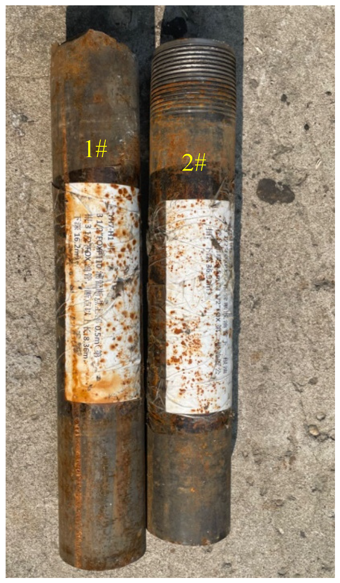
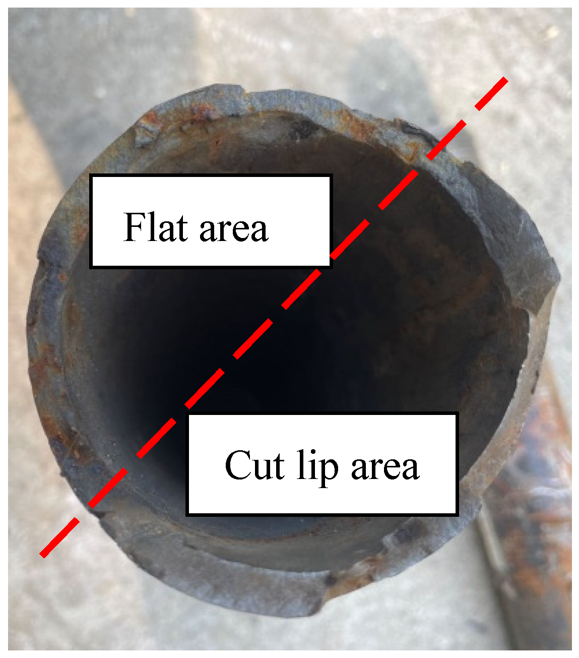
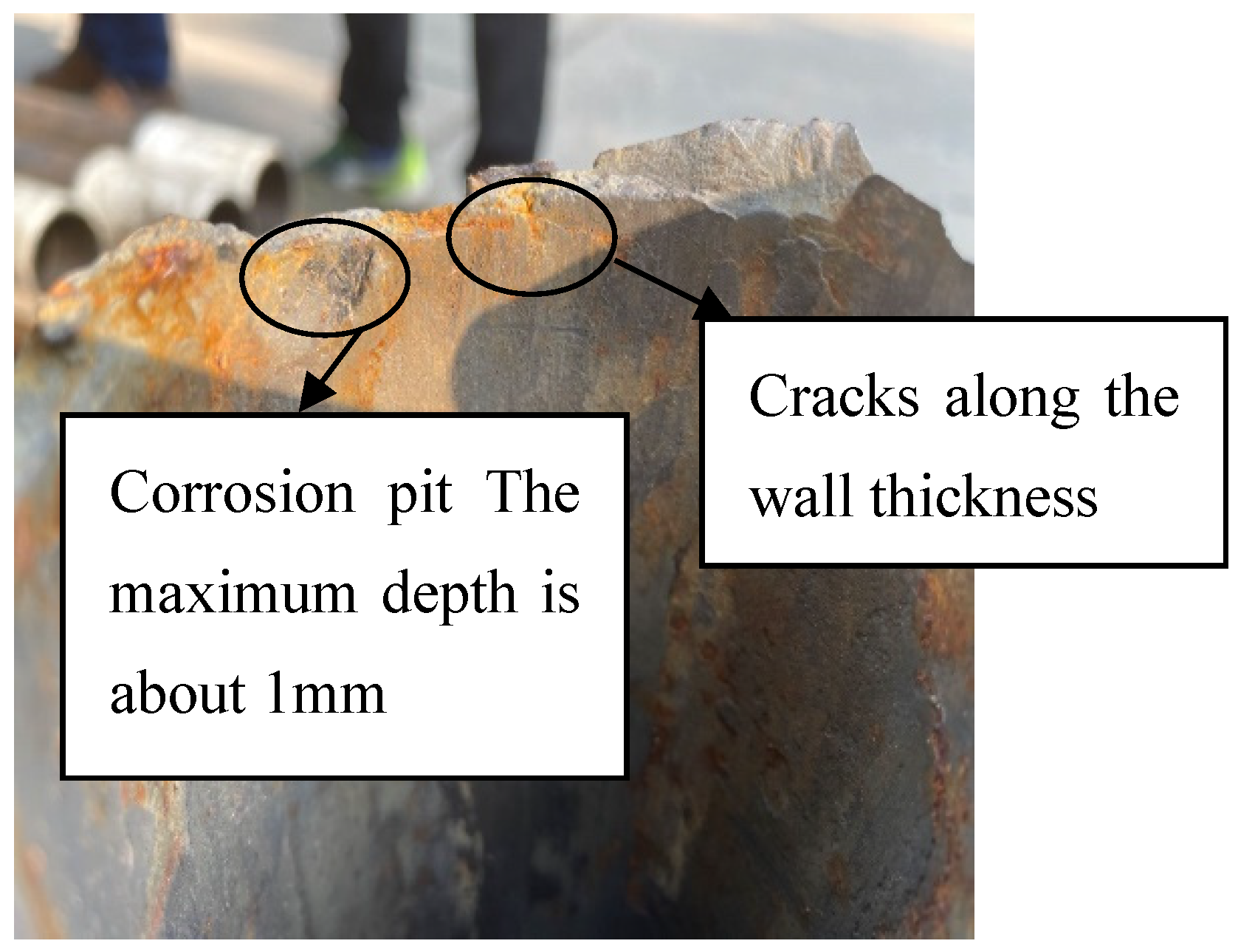
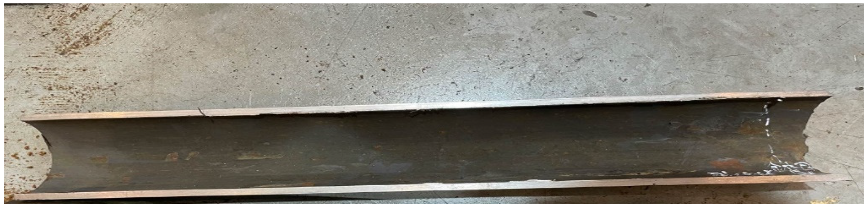
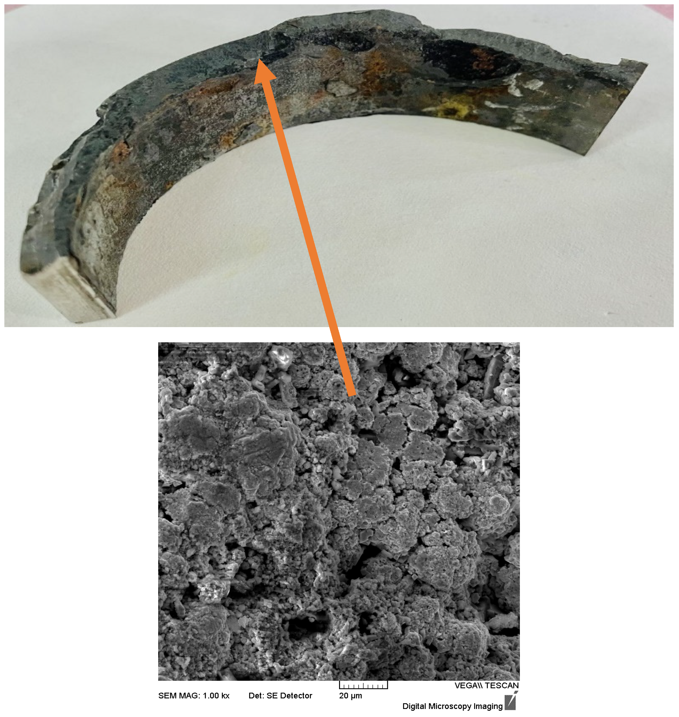
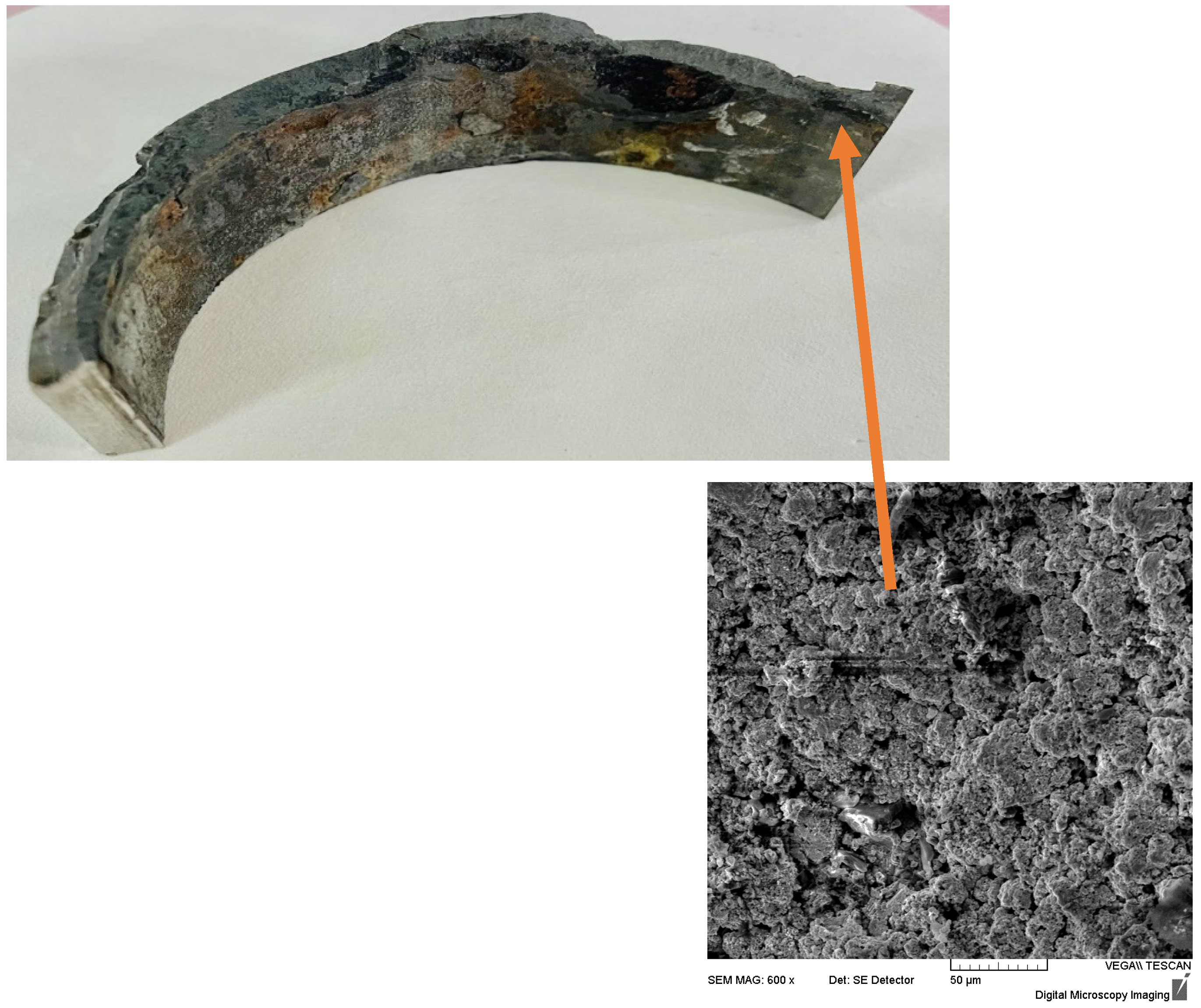
3. Macromorphological Analysis
4. Geometry Measurement
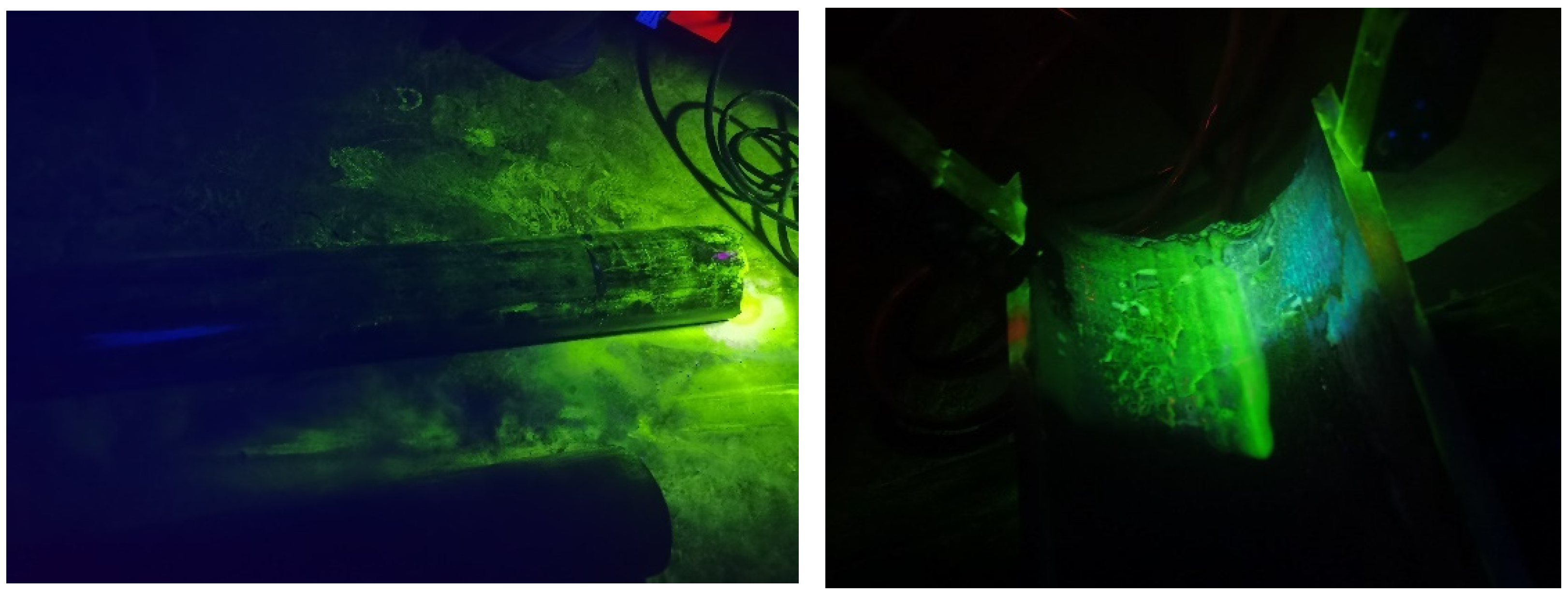
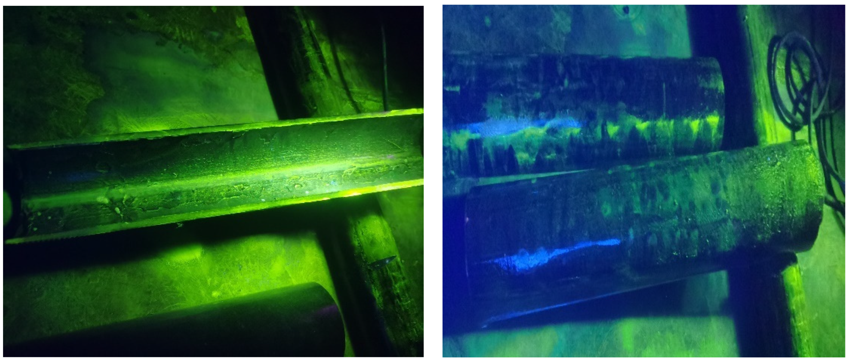
5. Non-Destructive Testing (NDT)
6. Chemical Composition Analysis
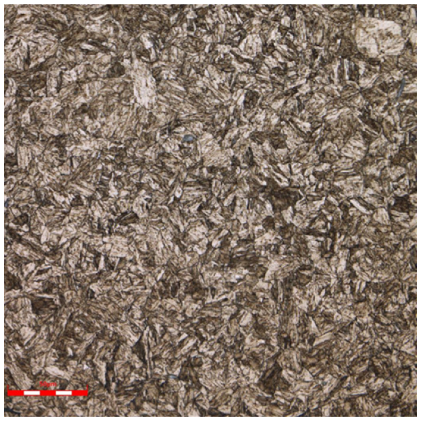
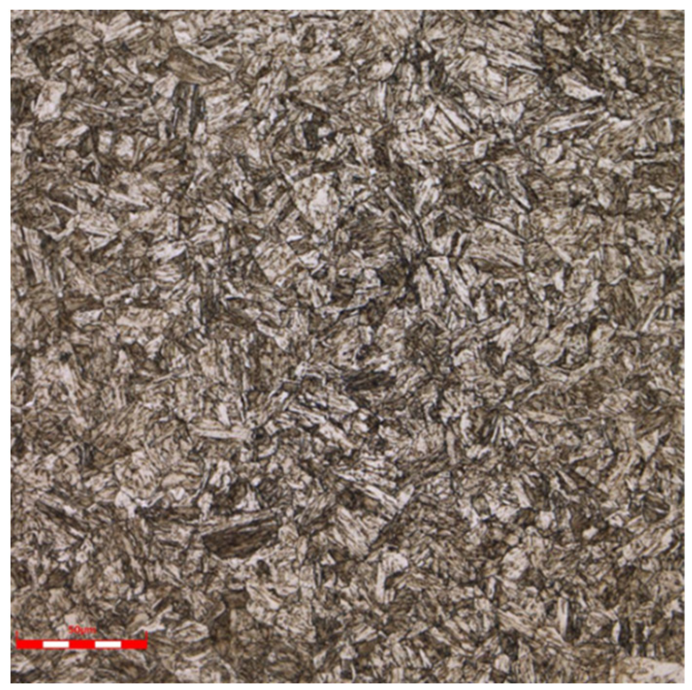
7. Metallographic Structure Analysis
8. Mechanical Property Test
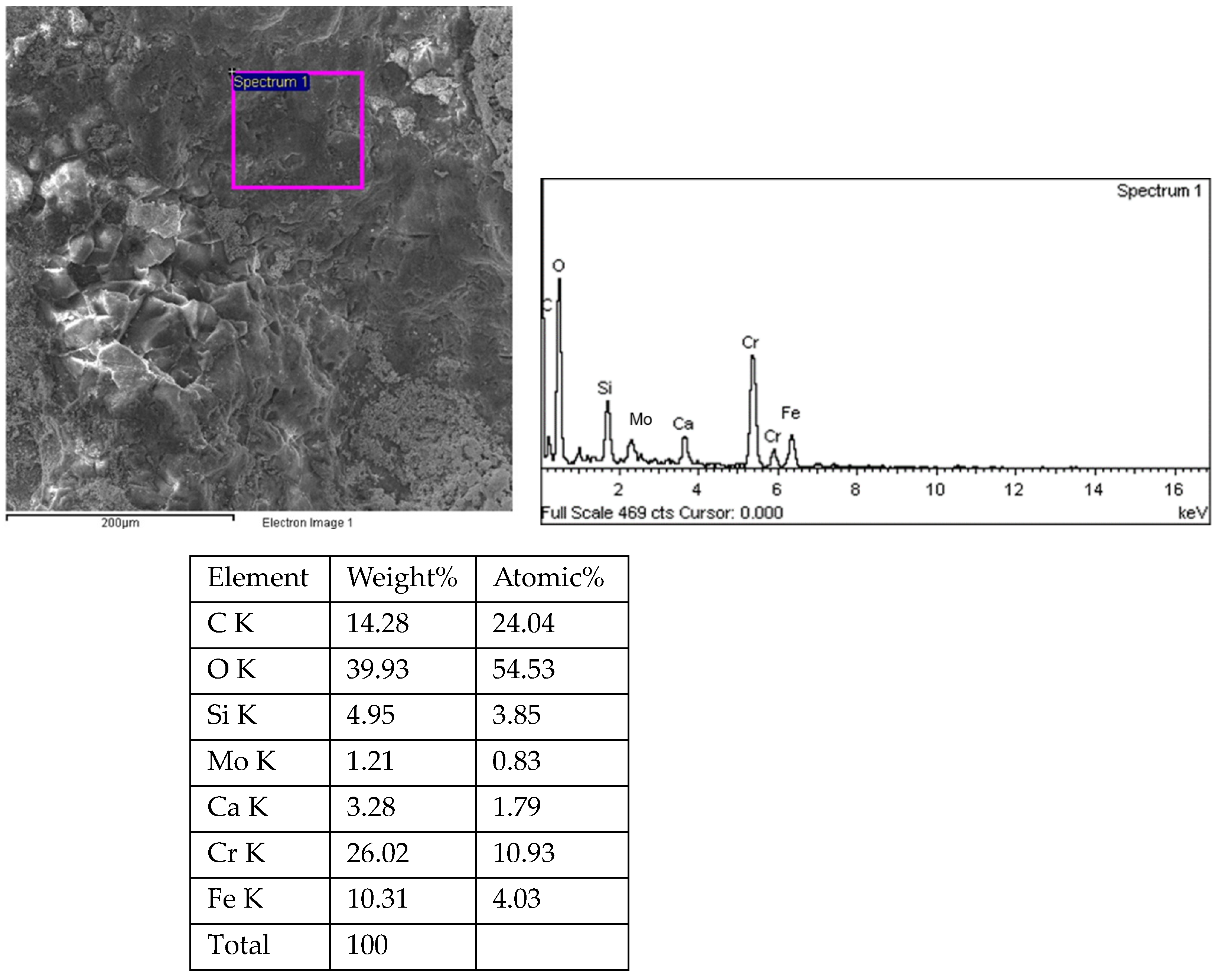
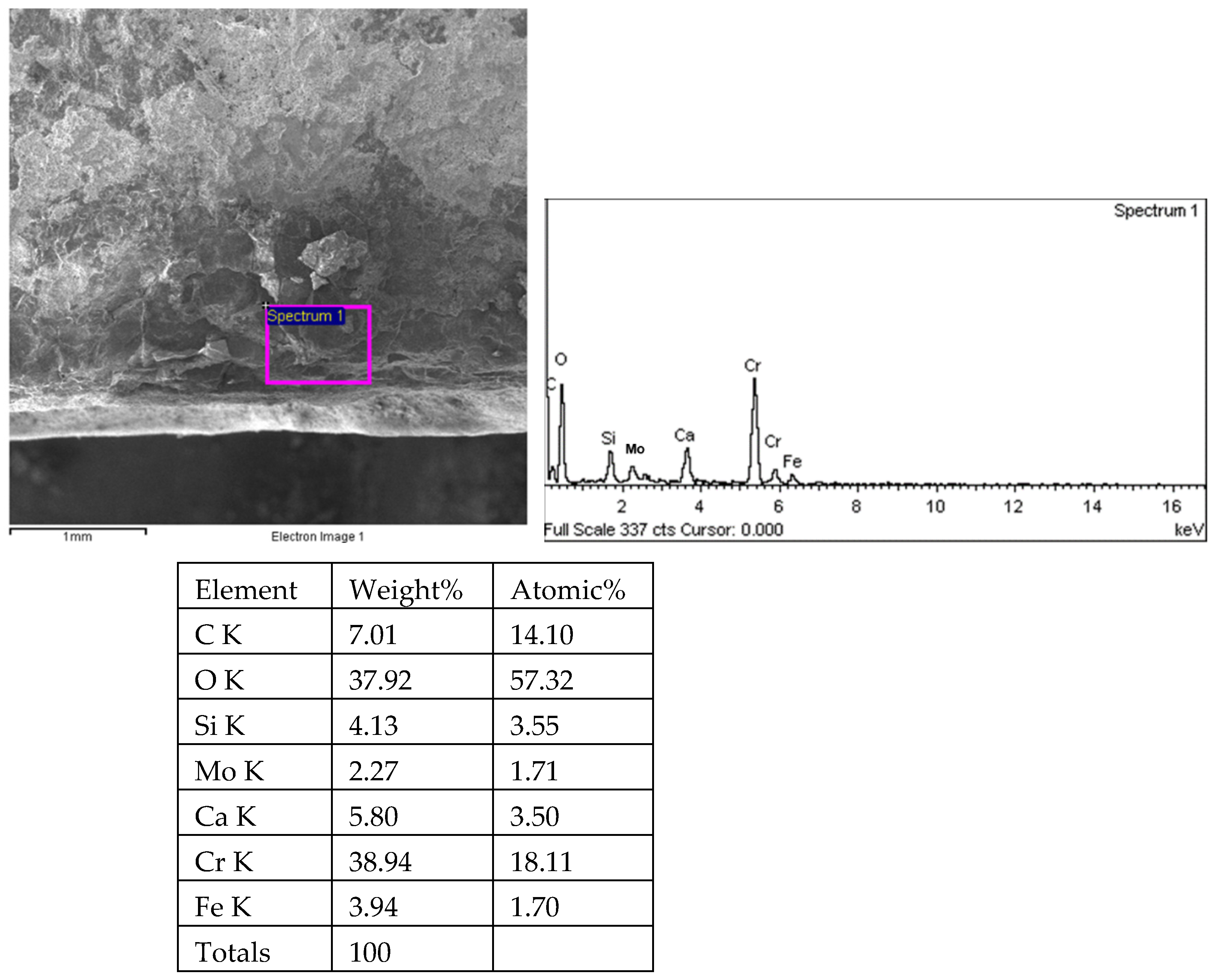
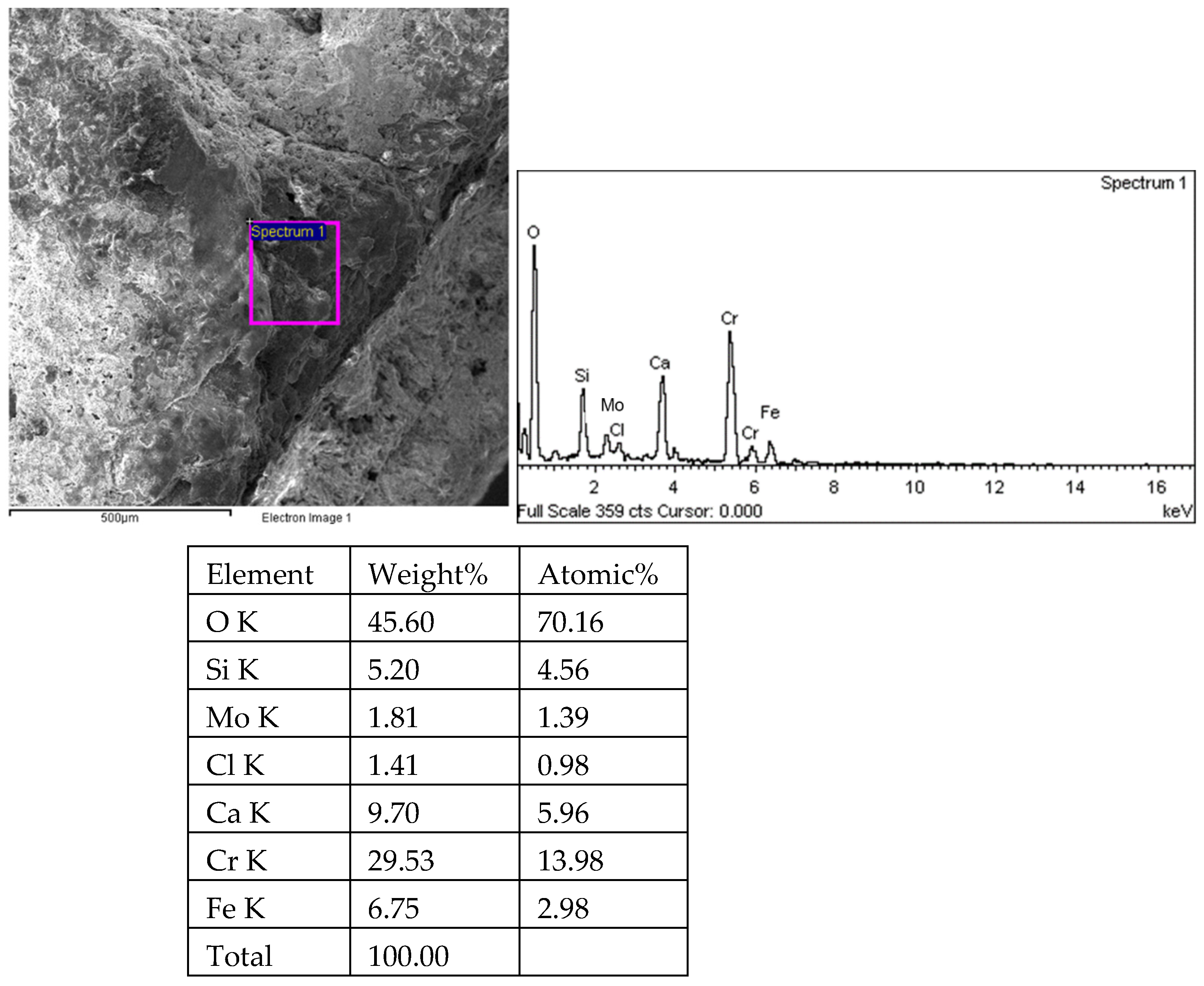
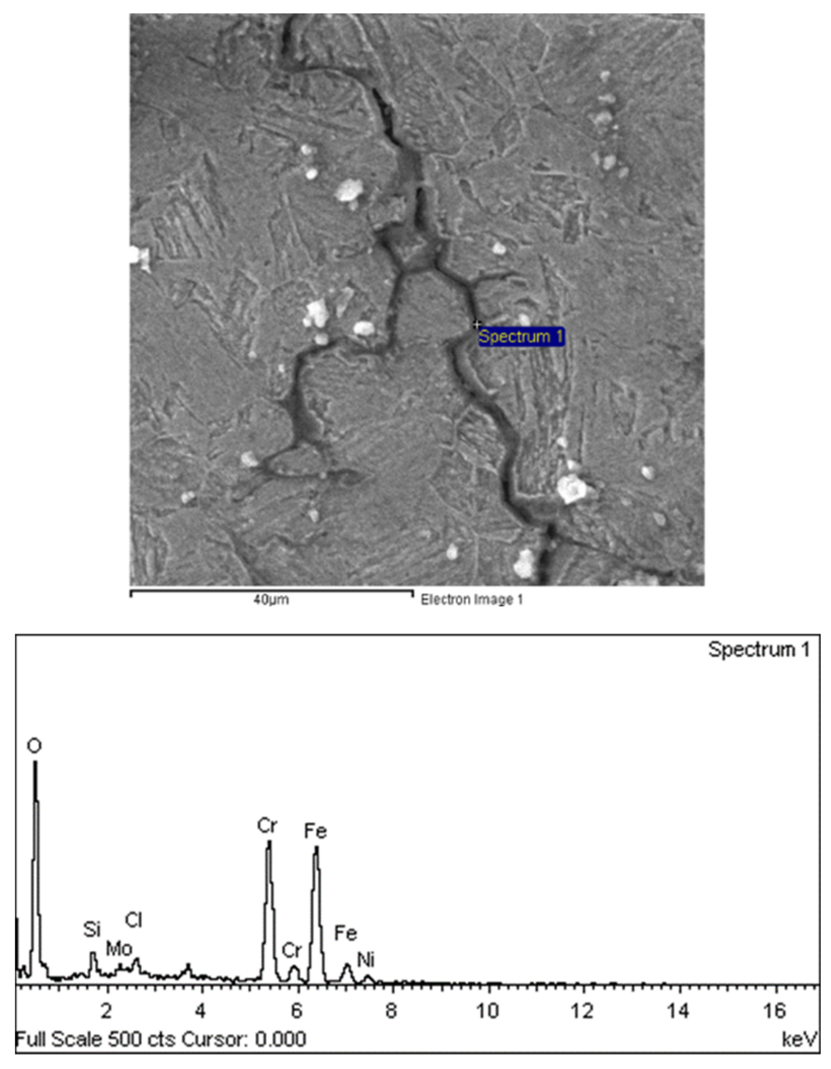
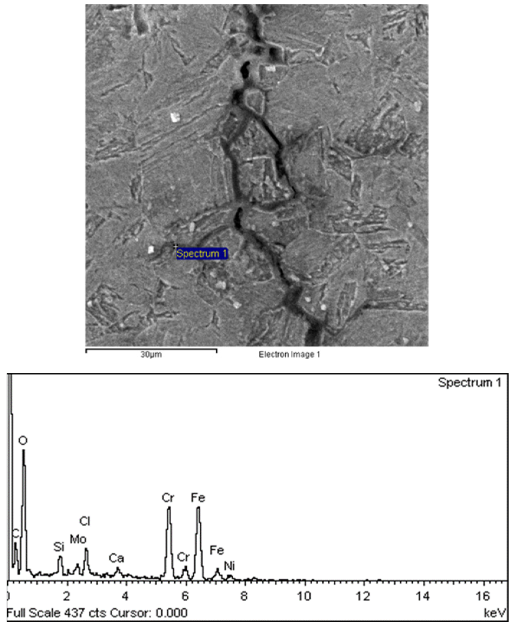
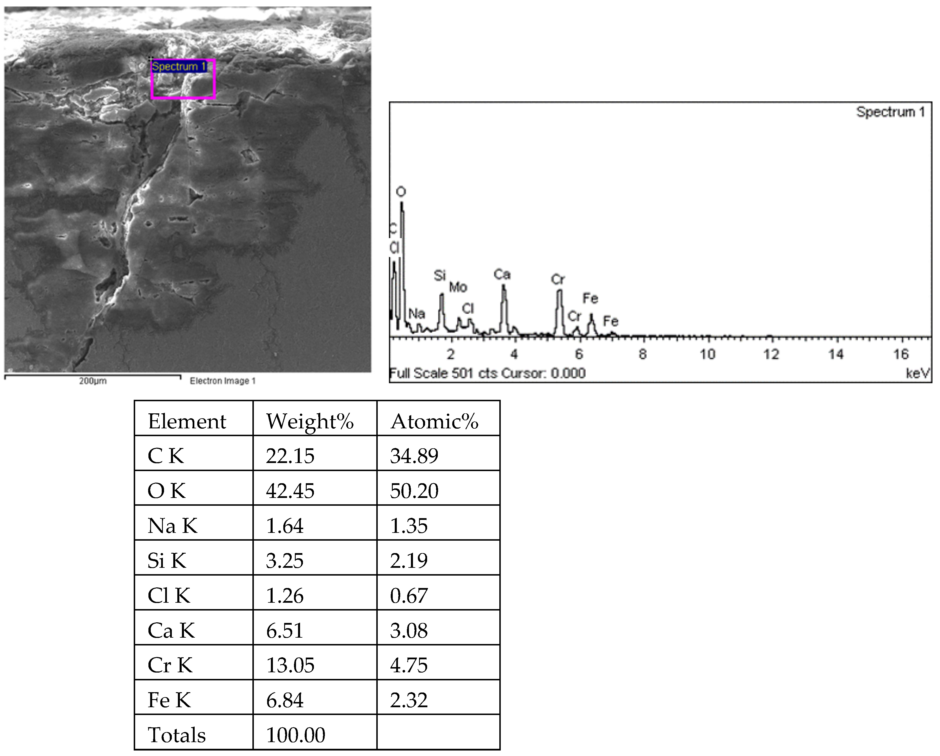
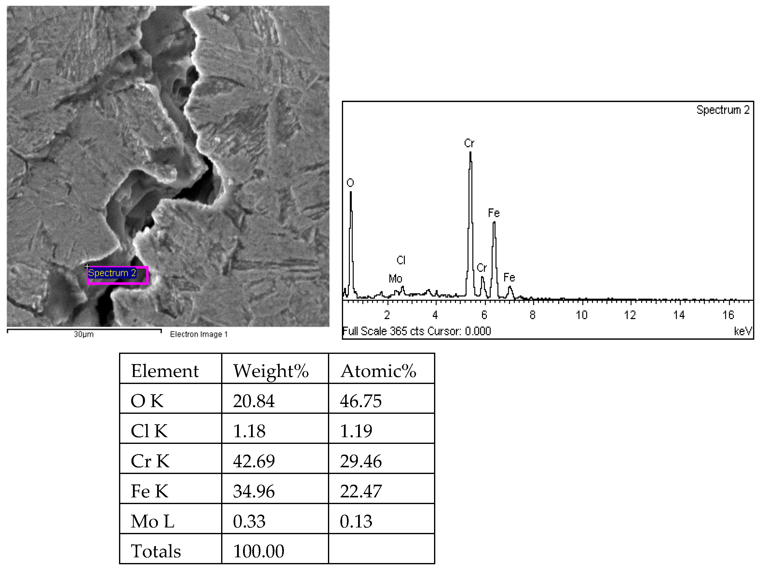
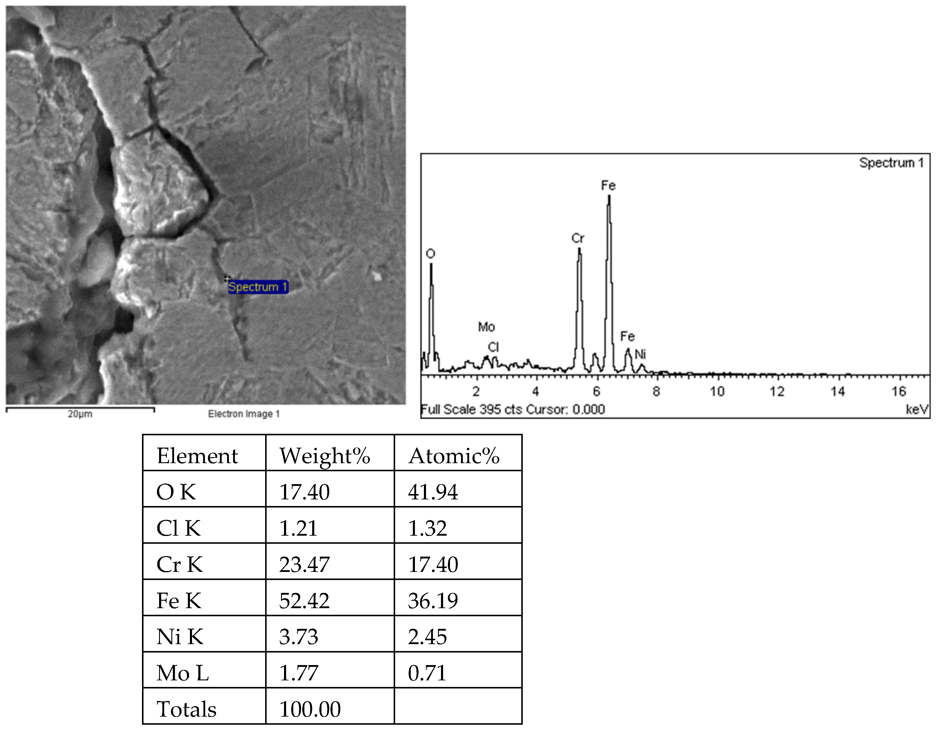
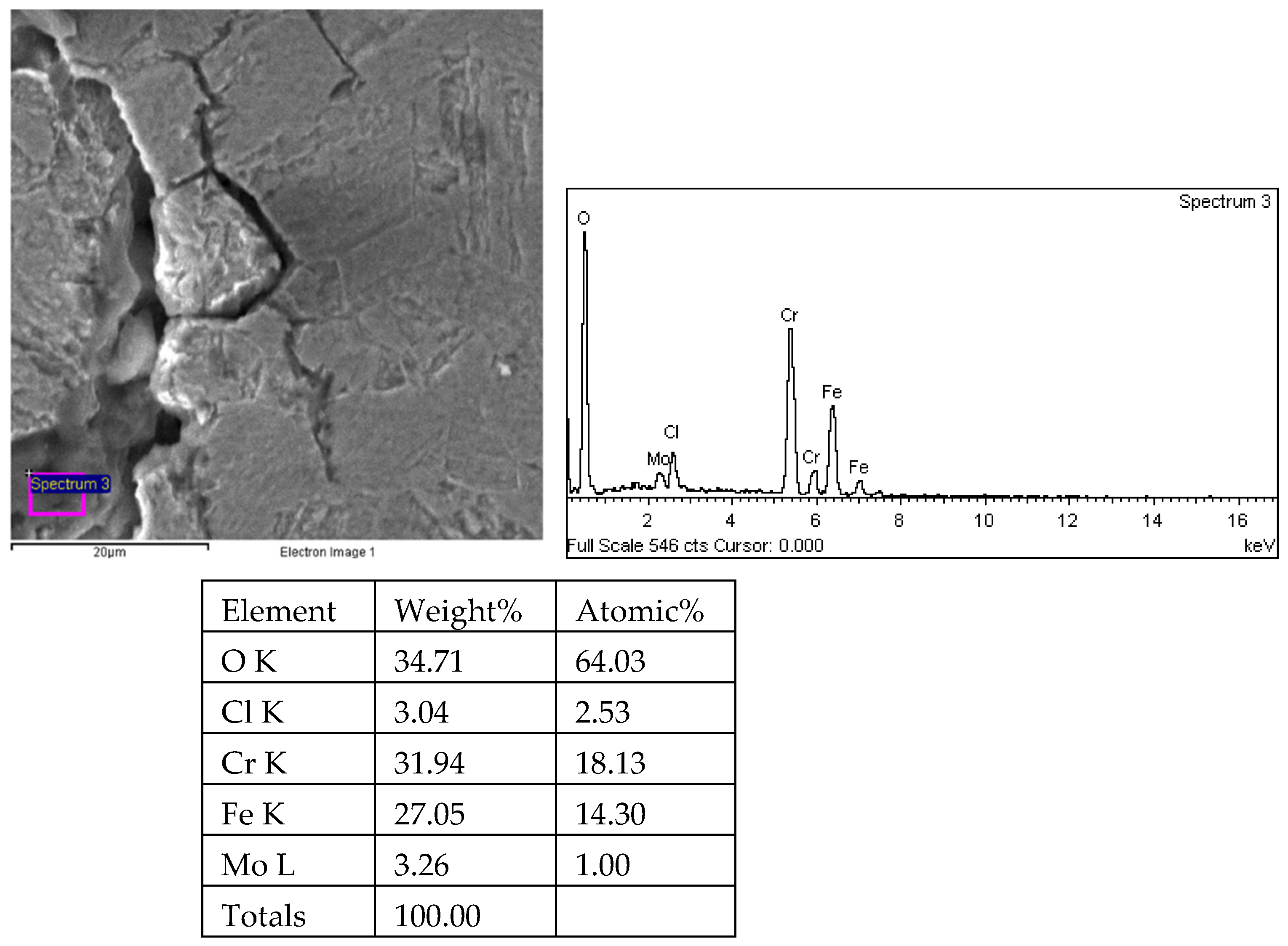
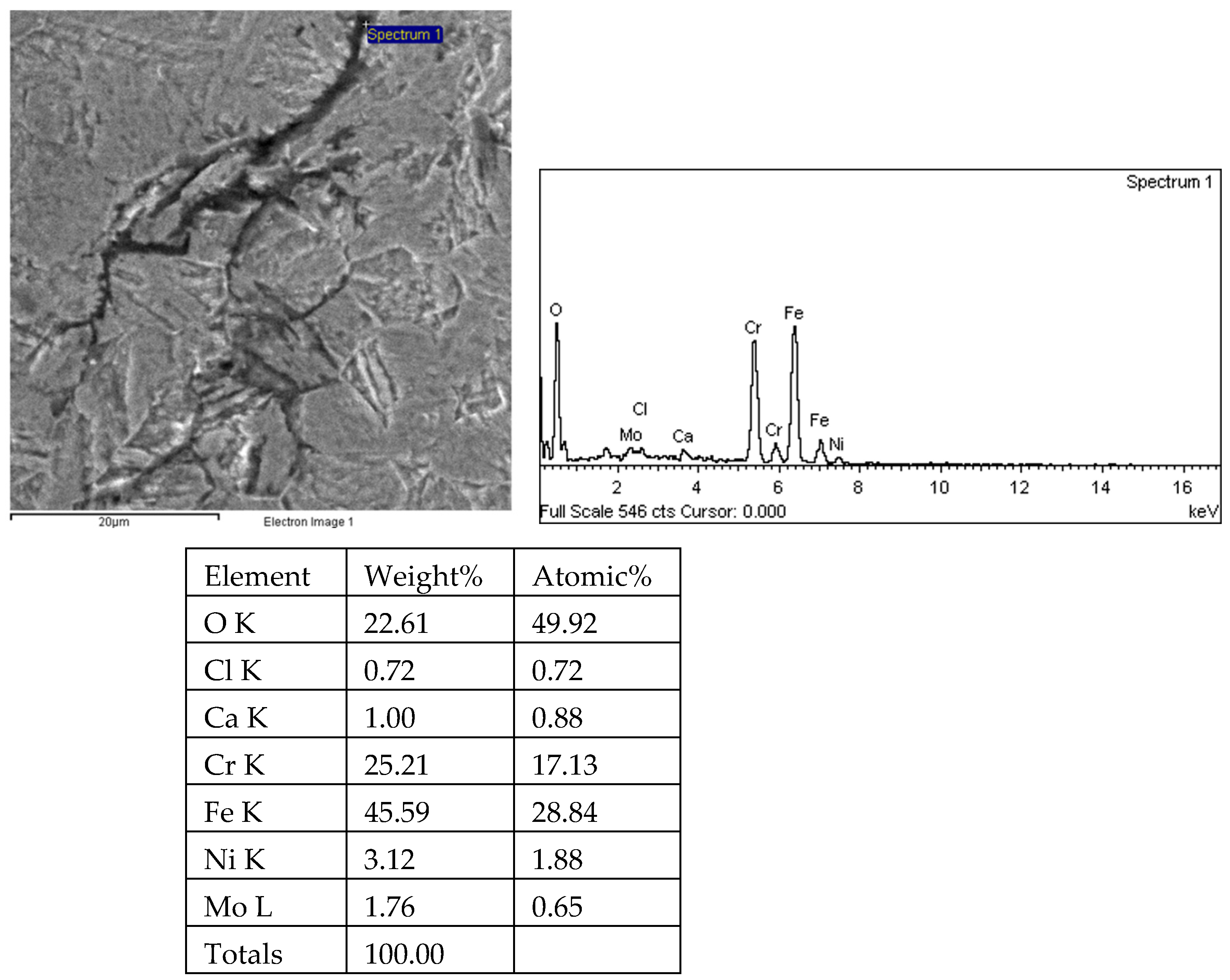
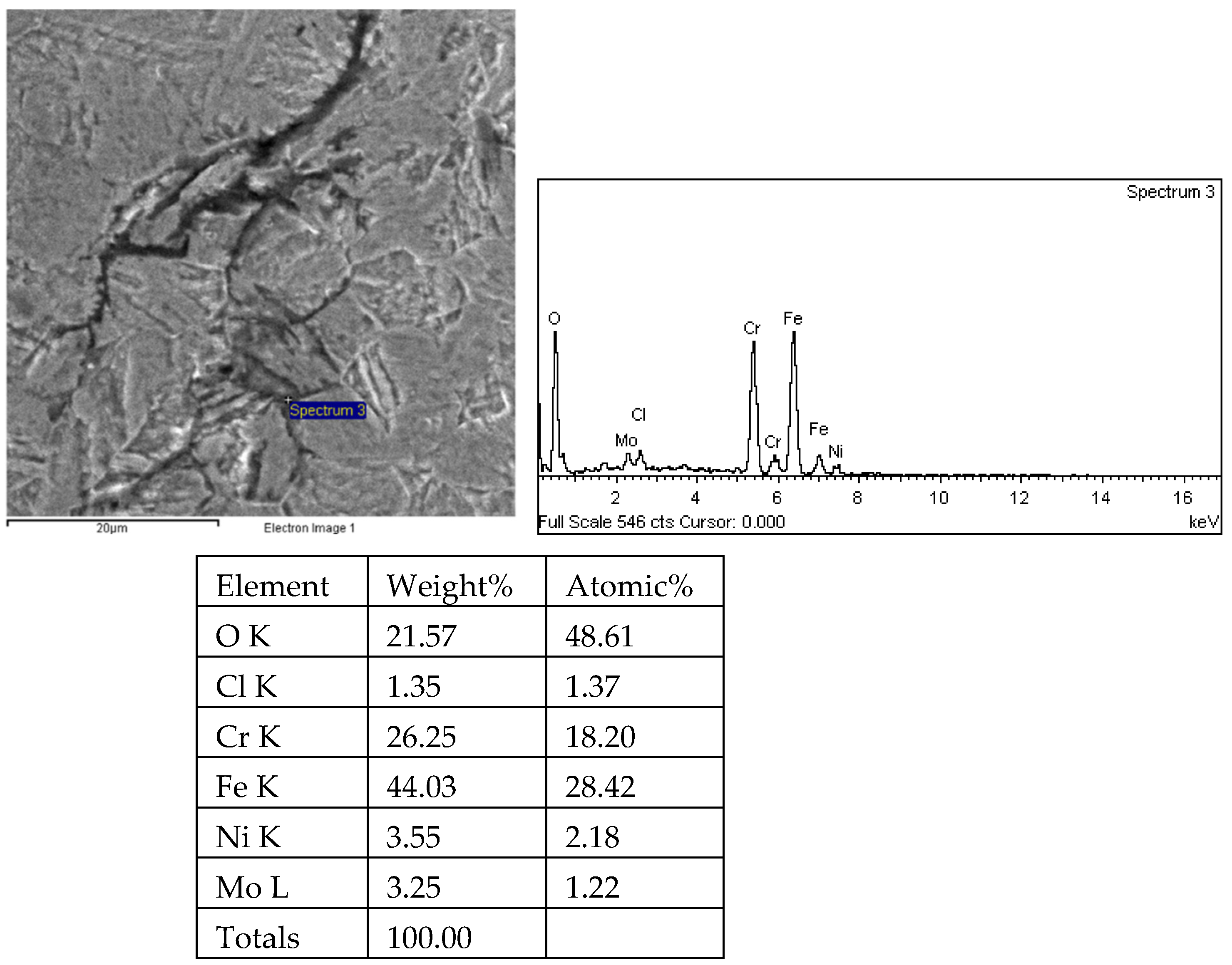
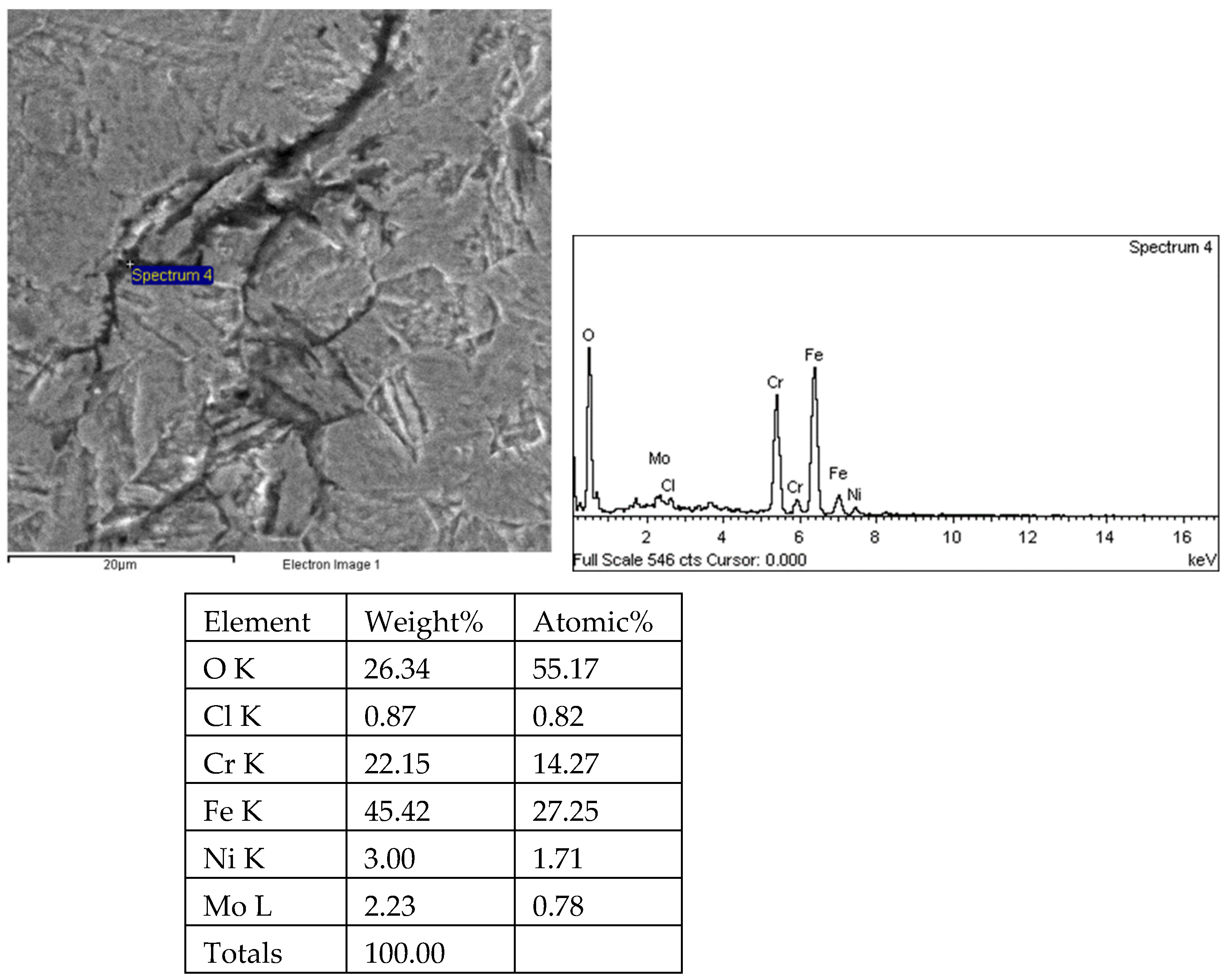
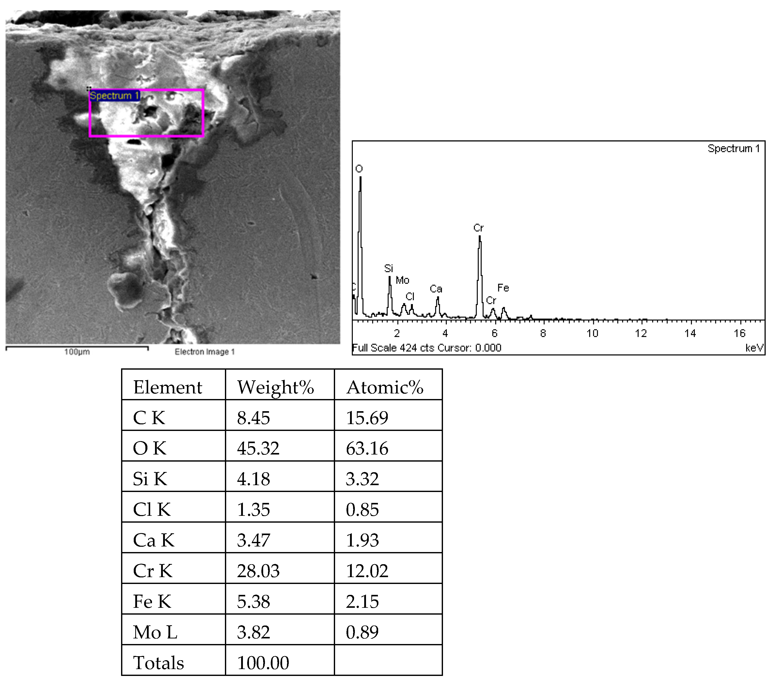
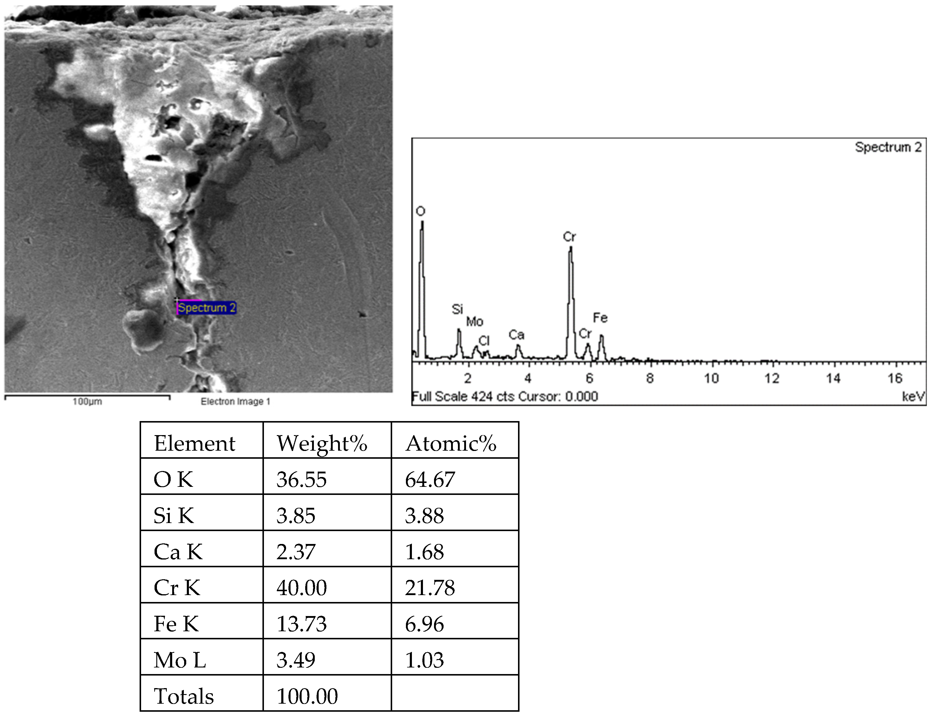
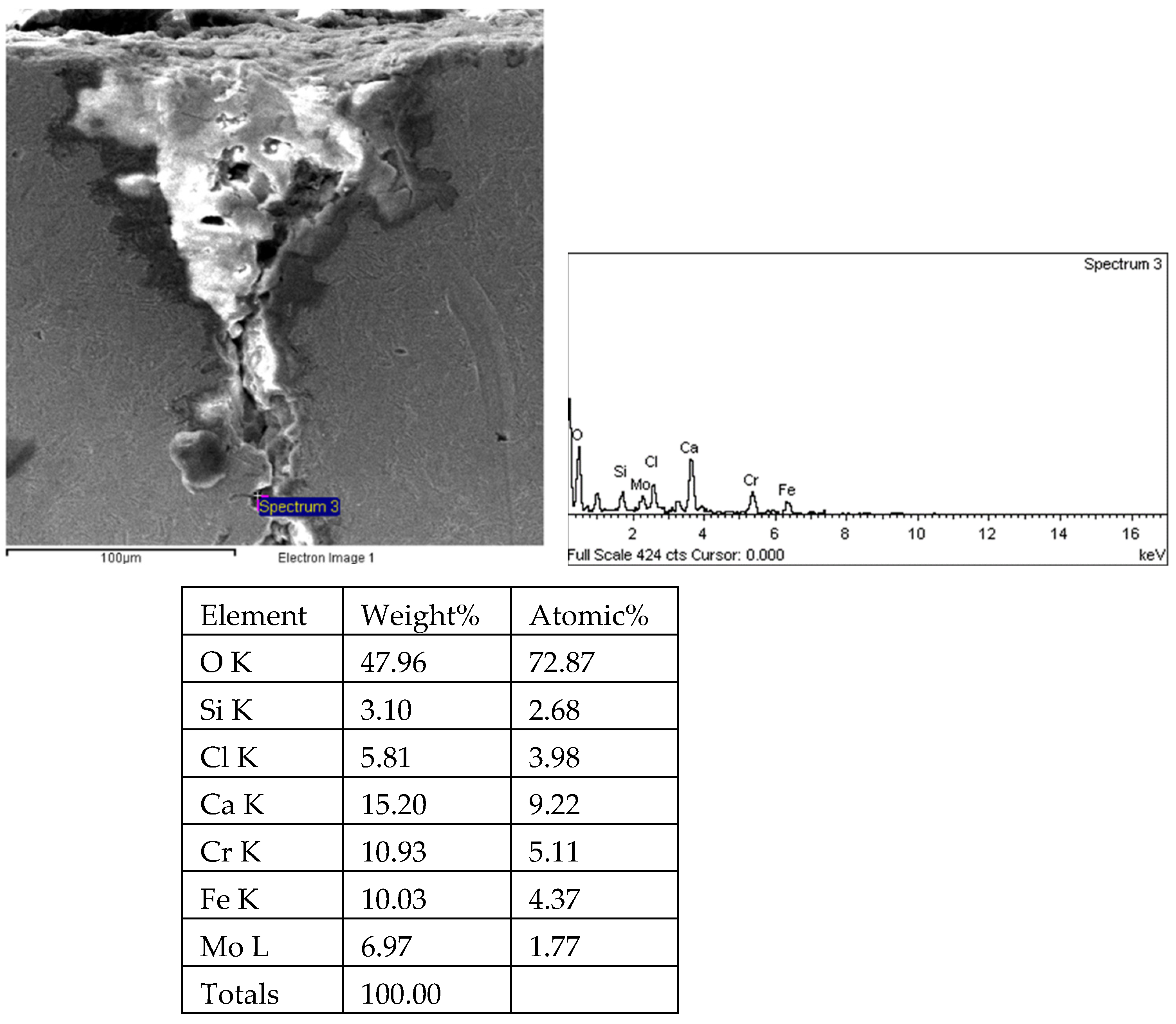
9. Microanalysis
10. Comprehensive Analysis
- (1)
- Sensitive metal materials
- (2)
- Specific corrosive media
- (3)
- A certain tensile stress
11. Conclusions and Recommendations
- (1)
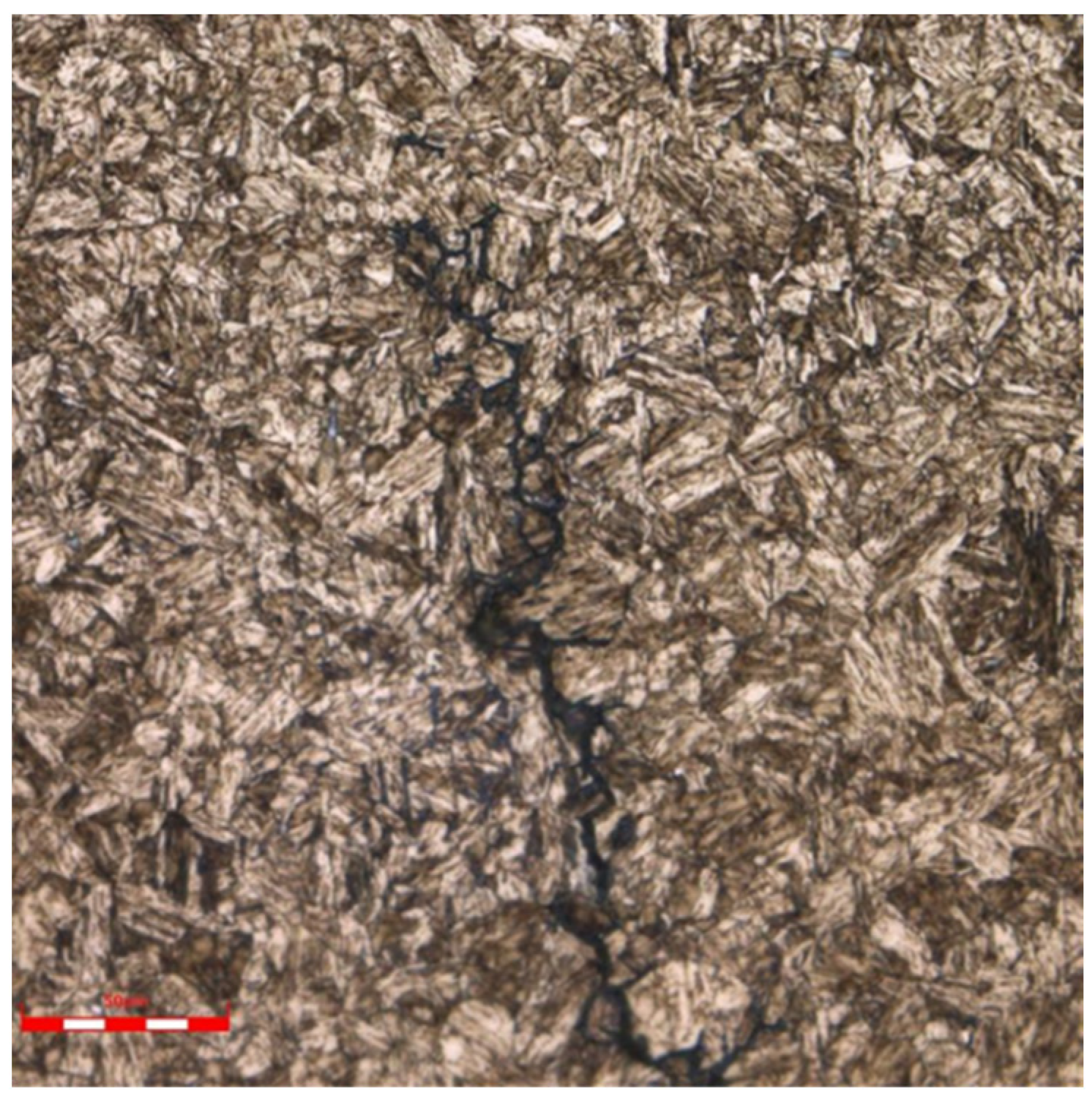
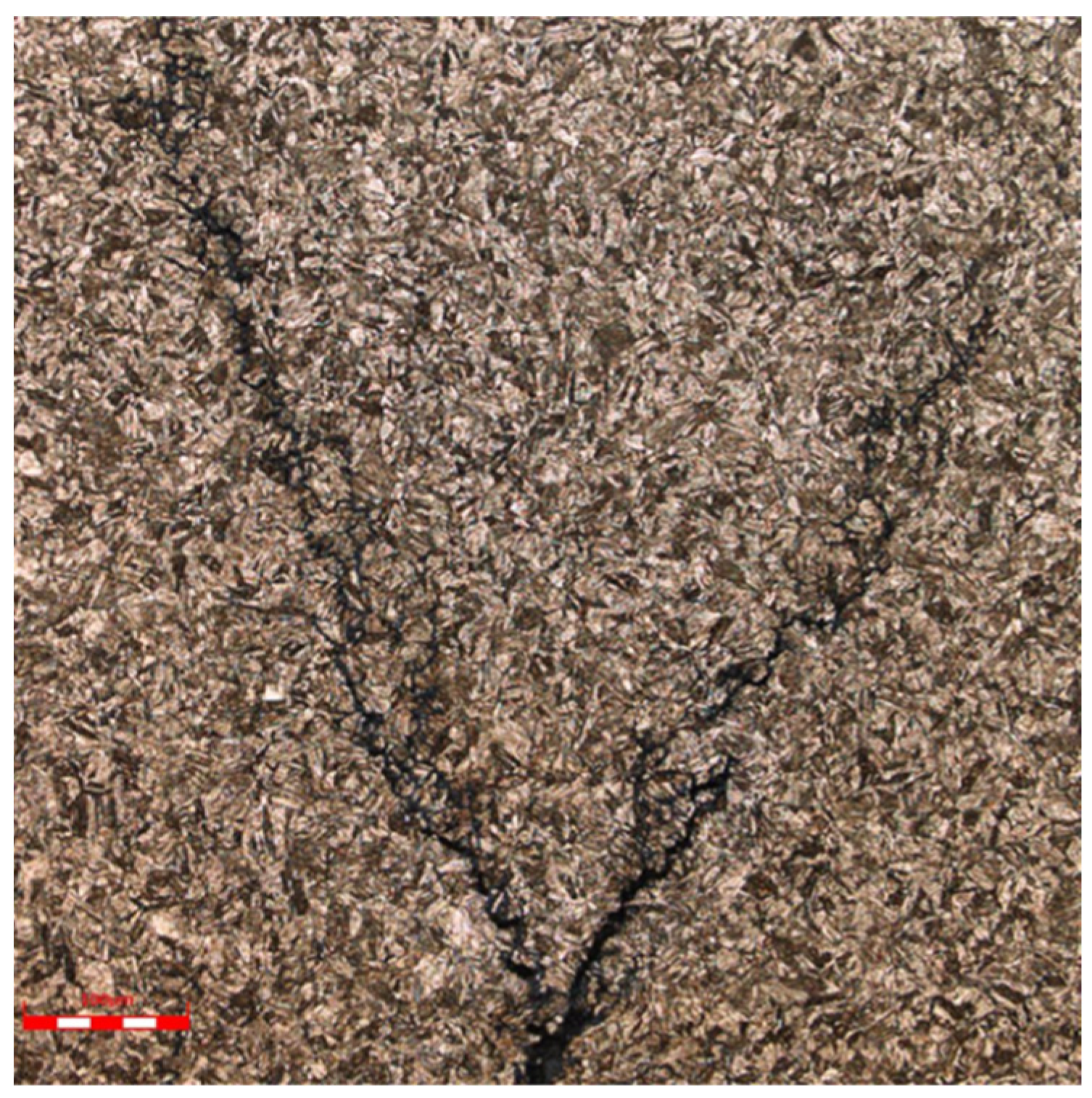
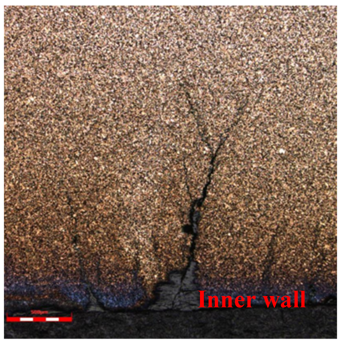
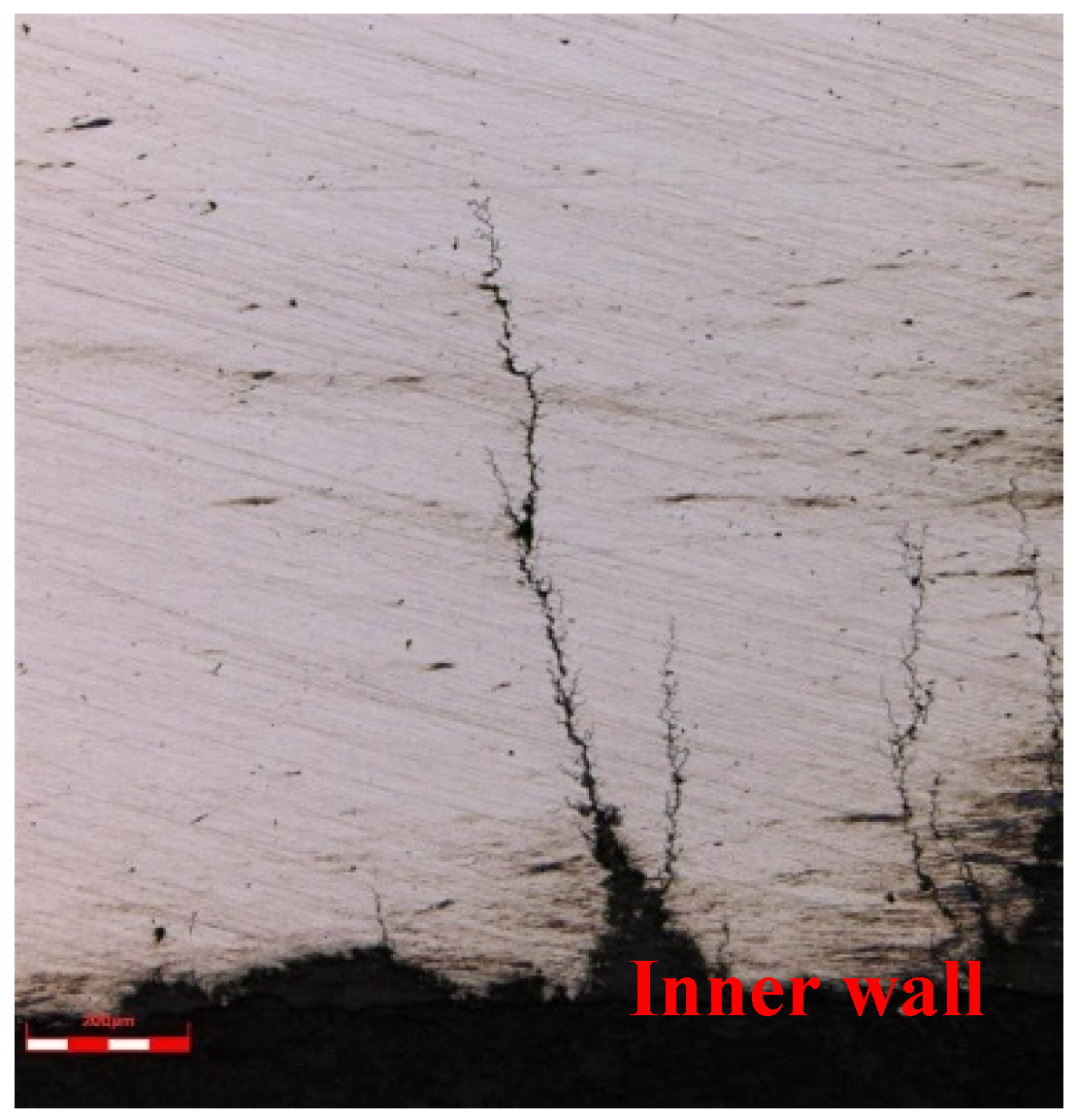
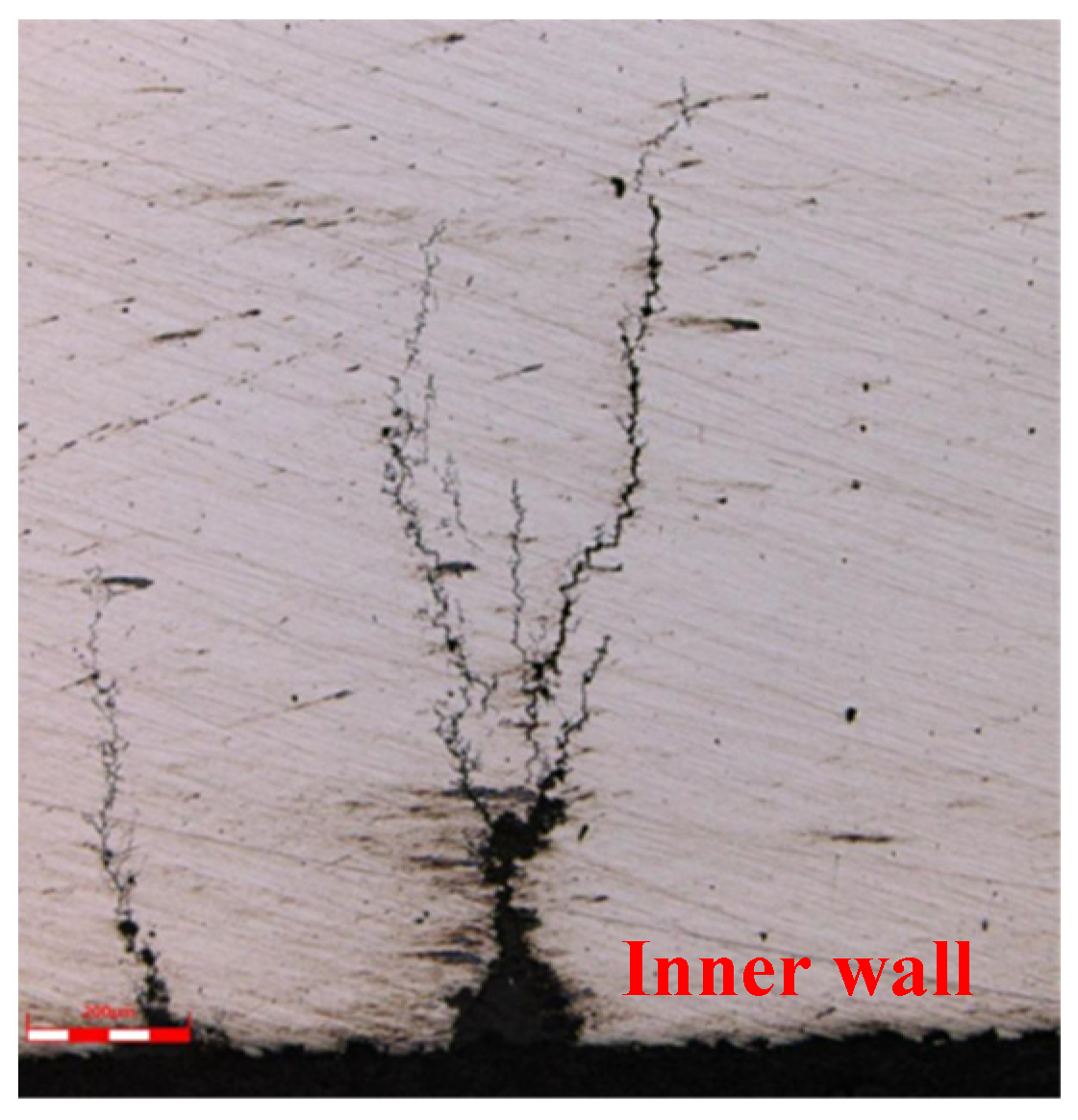
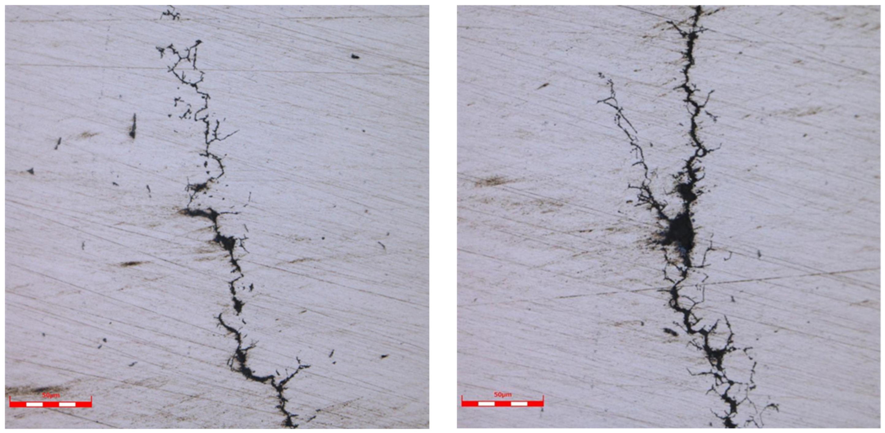
- The microscopic analysis of crack metallography shows that the crack originates from the inner wall of the oil pipe, extends along the crystal, and has branching at the tip, belonging to stress corrosion cracking.
- (2)
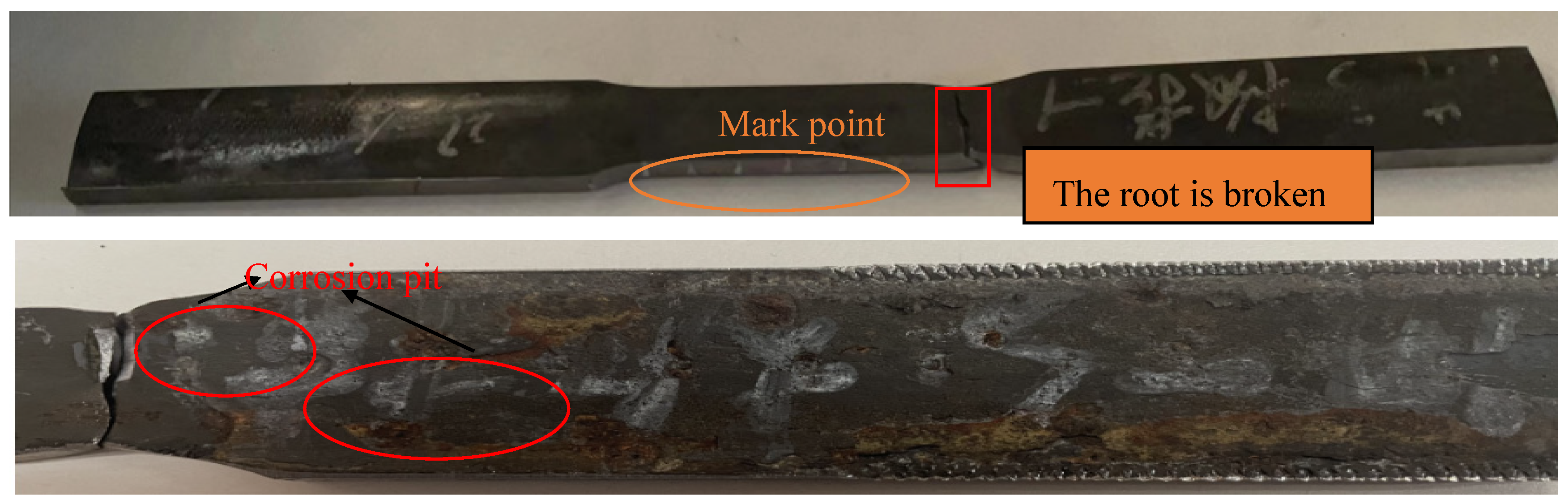
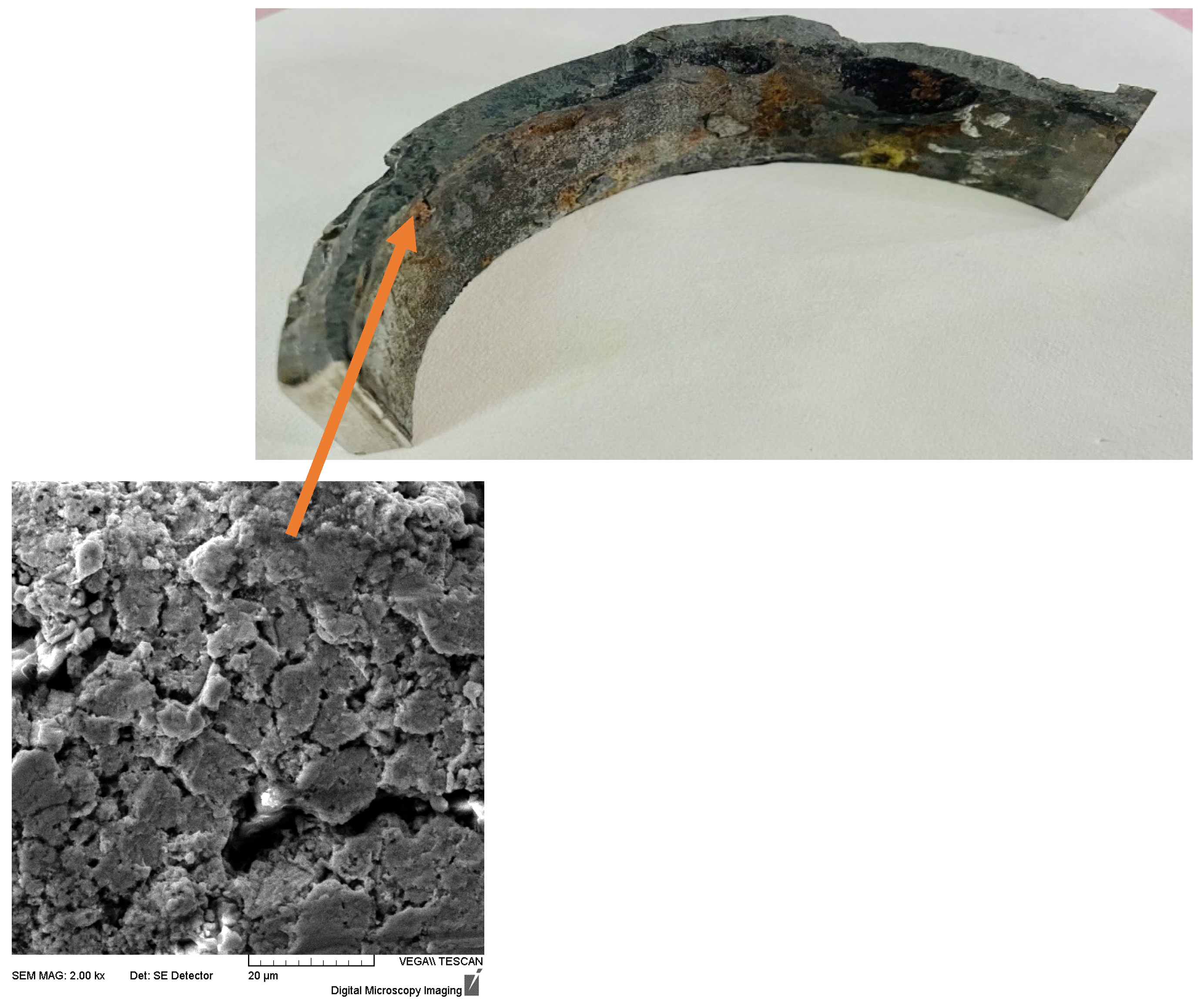
- The synergistic effect of Cl− and oxygen during gas lift drainage is an important reason for the stress corrosion cracking of the oil pipe. The failed oil pipe is located at the wellhead, where it is subjected to significant axial tensile stress and causes fractures.
- (3)
- It is recommended to strictly control the oxygen content in gas-lift operations and reduce the sensitivity of super 13Cr pipes to stress corrosion cracking.
- (4)
- The methods to reduce the susceptibility of super-13Cr steel to stress corrosion cracking (SCC) can be analyzed and implemented from multiple perspectives.
- ①
- Material composition optimization
- (1)
- Increase the content of molybdenum (Mo): molybdenum can significantly improve the material’s resistance to pitting and crevice corrosion, thus indirectly reducing SCC susceptibility.
- (2)
- (Adding trace elements: adding elements such as niobium (Nb), titanium (Ti), and other elements can improve the microstructure of the material, reducing the possibility of intergranular corrosion.
- (3)
- Control of carbon content: Low or ultra-low carbon design can reduce carbide precipitation, thereby reducing the risk of intergranular corrosion.
- ②
- Heat treatment process optimization
- (1)
- Solution treatment: Through high-temperature solution treatment, the residual stresses generated during welding or machining can be eliminated, and the grain can be refined to improve the toughness and corrosion resistance of the material.
- (2)
- Control the cooling rate: rapid cooling prevents precipitation of brittle phases (e.g., σ-phase) and thus reduces the material’s brittleness.
- (3)
- Avoid the chemical sensitization temperature interval: in the heat treatment process, prolonged exposure of the material to the sensitization temperature interval must be avoided to prevent intergranular corrosion from occurring.
- ③
- Environmental control
- (1)
- Reduce the concentration of corrosive media: reduce the concentration of corrosive media such as chloride ions and hydrogen sulfide in the environment by dilution or filtration.
- (2)
- Control temperature and pH: Avoid the prolonged use of the materials at high temperatures or extreme pH environments.
- (3)
- Regular cleaning of deposits: Prevent crevice corrosion from occurring, especially in areas where deposits may be present.
Author Contributions
Funding
Data Availability Statement
Conflicts of Interest
References
- Wang, Z.; Wang, P.; Zeng, D.; Shi, T.; Deng, W. A study on the influential factors of stress corrosion cracking in C110 casing pipe. Materials 2022, 15, 801. [Google Scholar] [CrossRef] [PubMed]
- Yao, J.; Zhong, X.; Xiong, Q.; Yu, J.; Hou, D.; Wang, Z.; Shi, T. Pitting Corrosion of S13Cr Tubing in a Gas Field: A Failure Case and Corrosion Mechanism Analysis. J. Fail. Anal. Prev. 2024, 24, 331–343. [Google Scholar] [CrossRef]
- Zhang, Z.; Zheng, Y.; Li, J.; Liu, W.; Liu, M.; Gao, W.; Shi, T. Stress corrosion crack evaluation of super 13Cr tubing in high-temperature and high-pressure gas wells. Eng. Fail. Anal. 2019, 95, 263–272. [Google Scholar] [CrossRef]
- Ji, N.; Zhao, M.; Wu, Z.; Wang, P.; Feng, C.; Xie, J.; Long, Y.; Song, W.; Xiong, M. Collapse failure analysis of S13Cr-110 tubing in a high-pressure and high-temperature gas well. Eng. Fail. Anal. 2023, 148, 107187. [Google Scholar] [CrossRef]
- Krishnan, K.; Shukla, S.; Verma, A. Fracture Toughness of 41XX Cr-Mo Steel, Super Martensitic Stainless Steel and Nickel Alloy in High Pressure Hydrogen Environment. In Proceedings of the AMPP Annual Conference, New Orleans, LA, USA, 3–7 March 2024; p. AMPP-2024-21083. [Google Scholar]
- Kamo, Y.; Ishiguro, Y.; Mizuno, Y. Environmentally-Assisted Cracking (SSC and SCC) of Martensitic Stainless Steel OCTG Material in Sour Environment in 5% NaCl and 20% NaCl Solution. In Proceedings of the AMPP Annual Conference & Expo 2022, San Antonio, TX, USA, 6–10 March 2022; p. D031S021R006. [Google Scholar]
- Yue, X.; Huang, L.; Qu, Z.; Yang, Z.; Zhang, L.; Hua, Y. Formation and Evolution of the Corrosion Scales on Super 13Cr Stainless Steel in a Formate Completion Fluid with Aggressive Substances. Front. Mater. 2022, 8, 802136. [Google Scholar] [CrossRef]
- Mubarak, G.; Elkhodbia, M.; Gadala, I.; AlFantazi, A.; Barsoum, I. Failure analysis, corrosion rate prediction, and integrity assessment of J55 downhole tubing in ultra-deep gas and condensate well. Eng. Fail. Anal. 2023, 151, 107381. [Google Scholar] [CrossRef]
- Yuan, Y.; Li, C.; Zhao, Y.; Zhang, F.; Xiang, Y. Crevice Corrosion Mechanism of L80-13cr in Cl-Containing Supercritical CO2 Water-Rich Phase Considering the Influence of SO2. Available online: https://papers.ssrn.com/sol3/papers.cfm?abstract_id=5067762 (accessed on 11 February 2025).
- Giarola, J.M.; Santos, B.A.F.; Souza, R.C.; Serenario, M.E.D.; Martelli, P.B.; Souza, E.A.; Gomes, J.A.C.P.; Bueno, A.H.S. Proposal of a novel criteria for soil corrosivity evaluation and the development of new soil synthetic solutions for laboratory investigations. Mater. Res. 2022, 25, e20210521. [Google Scholar] [CrossRef]
- Zhou, L.; Huang, X.; Song, W.; Huang, C.; Liu, H.; Wang, H. Multi-factor corrosion model of TP110TS steel in H2S/CO2 coexistence and life prediction of petroleum casings. Int. J. Press. Vessel. Pip. 2024, 209, 105204. [Google Scholar] [CrossRef]
- Thomas, B.J.C.; Al Kindi, M.; Braiki, A.S. Non Producing Environments Leading to Downhole CRA Completion Failures. In Proceedings of the AMPP Annual Conference, New Orleans, LA, USA, 3–7 March 2024; p. AMPP-2024-20620. [Google Scholar]
- Qi, W.; Gao, Q.; Zhao, Y.; Zhang, T.; Wang, F. Insight into the stress corrosion cracking of HP-13Cr stainless steel in the aggressive geothermal environment. Corros. Sci. 2021, 190, 109699. [Google Scholar] [CrossRef]
- Yue, X.; Cao, H.; Zhang, L.; Lu, M.; Ma, L.; Zhao, M.; Hua, Y. Effect of Aggressive Substance on the Nature of Corrosion Scales Formation on Super 13Cr Stainless Steel in Formate Completion Fluid. In Proceedings of the NACE Corrosion, Virtual, 19–30 2021; p. D081S030R001. [Google Scholar]
- Luo, S.; Fu, A.; Liu, M.; Xue, Y.; Lv, N.; Han, Y. Stress corrosion cracking behavior and mechanism of super 13Cr stainless steel in simulated O2/CO2 containing 3.5 wt% NaCl solution. Eng. Fail. Anal. 2021, 130, 105748. [Google Scholar] [CrossRef]
- GB/T 11170; Stainless Steel—Determina of Multi-Element Contents—Spark Discharge Atomic Emission Spectrometric Method (Routine Method). National Standard of the People’s Republic of China: Beijing, China, 2008.
- GB/T 228.1; Metallic Materials—Tensile Testing—Part 1: Method of Test at Room Temperature. National Standard of the People’s Republic of China: Beijing, China, 2021.
- GB/T 229; Matallic Materials—Charpy Pendulum Impact Test—Part 1: Test Method, MOD. National Standard of the People’s Republic of China: Beijing, China, 2020.
- GB/T 230.1; Metallic Materials—Rockwell Hardness Test—Part 1: Test Method. National Standard of the People’s Republic of China: Beijing, China, 2018.


| Gas Lift Drain Start and End Dates | Maximum Depth (m) | Cumulative Liquid Displacement (m3) | Cumulative Nitrogen Injection Volume (m3) | Injection Pressure Range (MPa) |
|---|---|---|---|---|
| 7 April 2013~9 April 2013 | 1600 | 410.75 | 55,800 | 5.5~14 |
| 2 October 2017~4 November 2017 | 1400 | 10,999.49 | 270,900 | 12~20 |
| 18 August 2019~20 August 2019 | 2500 | 1196.73 | 36,600 | 5.5~14 |
| Sample Testing | Asphaltenes (%) | Colloid (%) | Sulfur Content (%) | Wax Content (%) |
|---|---|---|---|---|
| 1 | 0.98 | 0.36 | 0.080 | 34.100 |
| 2 | 0.23 | 0.49 | 0.030 | 32.300 |
| 3 | 0.42 | 0.80 | 0.040 | 29.400 |
| Sampling Location | Methane, % | Ethane, % | Propane, % | Nitrogen, % | Oxygen, % | Carbon Dioxide, % | Hydrogen Sulfide, % |
|---|---|---|---|---|---|---|---|
| Separator sampling port | 79.73 | 9.389 | 2.87 | 3.902 | 0.0791 | 0.8885 | - |
| Gas Gathering Station | 80.25 | 8.404 | 2.474 | 5.711 | 0.6547 | 0.8984 | - |
| Density g/cm3 | pH | CO32− (mg/L) | HCO3− (mg/L) | Cl− (mg/L) | Calcium (mg/L) | Water Type | Mineralization (mg/L) |
|---|---|---|---|---|---|---|---|
| 1.1351 | - | 0 | 97.9 | 119,200 | 6890.0 | Calcium chloride | 196,100 |
| 1.1336 | - | 0 | 113.0 | 113,300 | 6620.0 | Calcium chloride | 186,000 |
| 1.1259 | - | 0 | 81.8 | 114,800 | 6990.0 | Calcium chloride | 188,400 |
| Sample | ID | Outer Diameter D (mm) | Wall Thickness t (mm) | ||||||
|---|---|---|---|---|---|---|---|---|---|
| 0~180° | 90~270° | 135–315° | 45–225° | 0° | 90° | 180° | 270° | ||
| 1# Broken oil pipe | 1 | 88.54 | 89.52 | 88.92 | 89.52 | 6.50 | 6.20 | 6.93 | 6.26 |
| 2 | 89.52 | 88.51 | 89.24 | 89.64 | 6.56 | 6.10 | 6.48 | 6.58 | |
| 3 | 88.34 | 88.72 | 88.24 | 88.56 | 6.54 | 6.42 | 6.54 | 7.03 | |
| 4 | 88.68 | 89.67 | 88.12 | 89.06 | 6.63 | 6.78 | 6.78 | 6.49 | |
| 5 | 88.84 | 89.54 | 89.06 | 89.32 | 6.63 | 6.49 | 6.78 | 6.46 | |
| 6 | 88.90 | 89.60 | 89.36 | 89.40 | 6.67 | 6.52 | 6.78 | 6.65 | |
| Wall thickness of fracture area | 6.56 | 5.72 | 6.77 | 6.86 | |||||
| 2# oil pipe | 1 | 88.68 | 89.06 | 88.84 | 88.92 | 6.20 | 6.93 | 6.54 | 6.61 |
| 2 | 89.54 | 89.67 | 89.60 | 89.24 | 6.10 | 6.48 | 6.59 | 6.63 | |
| 3 | 88.90 | 89.12 | 89.21 | 88.32 | 6.42 | 7.03 | 6.61 | 6.59 | |
| 4 | 89.36 | 88.98 | 89.12 | 89.06 | 6.78 | 6.78 | 6.61 | 6.67 | |
| 5 | 88.4 | 89.35 | 89.35 | 89.32 | 6.49 | 6.58 | 6.64 | 6.60 | |
| 6 | 88.9 | 88.7 | 88.46 | 89.40 | 6.52 | 6.68 | 6.70 | 6.83 | |
| technology standard | Outer diameter tolerance: ±0.79 | ≥5.805 | |||||||
| Element | C | Si | Mn | P | S | Cr | Mo | Ni | Nb | V | Ti | Cu | B | Al | |
|---|---|---|---|---|---|---|---|---|---|---|---|---|---|---|---|
| Sample | |||||||||||||||
| 1# oil pipe body | 0.035 | 0.23 | 0.41 | 0.017 | 0.0007 | 13.07 | 0.87 | 4.59 | 0.000001 | 0.011 | 0.0016 | 0.024 | 0.0006 | 0.02 | |
| 2# oil pipe body | 0.034 | 0.19 | 0.39 | 0.017 | 0.0007 | 13.00 | 0.87 | 4.51 | 0.000001 | 0.011 | 0.0014 | 0.026 | 0.0006 | 0.02 | |
| JFE Oil well pipe product brochure JFE-HP1-13Cr | ≤0.04 | ≤0.5 | ≤0.6 | ≤0.02 | ≤0.005 | 12–14 | 0.8–1.5 | 4.5–5.5 | / | / | / | / | / | / | |
| Sample | Non-Metallic Inclusions | Composition | Grain Size | |||||||
|---|---|---|---|---|---|---|---|---|---|---|
| A | B | C | D | |||||||
| Thin | Thick | Thin | Thick | Thin | Thick | Thin | Thick | |||
| 1# oil pipe | 0.5 | 0 | 0.5 | 0 | 0 | 0 | 0.5 | 0 | Mshaped | 9.5 |
| 2# oil pipe | 0.5 | 0 | 0.5 | 0 | 0 | 0 | 0.5 | 0 | Mshaped | 9.5 |
| Sample | Tensile Strength (MPa) | Yield Strength (MPa) | Elongation After Break (%) | |
|---|---|---|---|---|
| ID | Diameter/Width × Gauge Length mm | |||
| 1#-1 | 19.1 × 50 | 878 | 825 | 23.5 |
| 1#-2 | 852 | 805 | 22.5 | |
| 1#-3 | 865 | 827 | 12.5 * | |
| 2#-1 | 19.1 × 50 | 874 | 818 | 17.0 |
| 2#-2 | 875 | 818 | 20.5 | |
| 2#-3 | 879 | 812 | 24.0 | |
| technology standard | / | ≥827 | 758–965 | ≥16 |
| Sample | Temperature °C | Absorbed Energy (Converted to 10 × 10) J, Conversion Factor 0.55 | ||||
|---|---|---|---|---|---|---|
| ID | Specification mm | Notch Shape | ||||
| 1# Oil pipe body lengthwise | 5 × 10 × 55 | V | −10 | 114 | 112 | 125 |
| 2# Oil pipe body lengthwise | 110 | 110 | 112 | |||
| technology standard | 5 × 10 × 55 | V | −10 | ≥77 (Conversion factor 0.55) | ||
| Measuring Position | Quadrant | Hardness Test Results (HRC) | |
|---|---|---|---|
| ID | |||
| 1# Tube body transverse | Quadrant 1 | 28.6, 29.2, 28.9 | |
| Quadrant 2 | 28.8, 28.9, 28.7 | ||
| Quadrant 3 | 28.6, 28.7, 28.3 | ||
| Quadrant 4 | 28.5, 28.4, 28.1 | ||
| 2# Tube body transverse | Quadrant 1 | 27.4, 27.7, 27.7 | |
| Quadrant 2 | 27.5, 27.3, 27.2 | ||
| Quadrant 3 | 28.2, 28.3, 28.5 | ||
| Quadrant 4 | 27.8, 27.6, 27.4 | ||
| technology standard | ≦32 | ||
Disclaimer/Publisher’s Note: The statements, opinions and data contained in all publications are solely those of the individual author(s) and contributor(s) and not of MDPI and/or the editor(s). MDPI and/or the editor(s) disclaim responsibility for any injury to people or property resulting from any ideas, methods, instructions or products referred to in the content. |
© 2025 by the authors. Licensee MDPI, Basel, Switzerland. This article is an open access article distributed under the terms and conditions of the Creative Commons Attribution (CC BY) license (https://creativecommons.org/licenses/by/4.0/).
Share and Cite
Xu, K.; Xie, S.; Luo, J.; Wang, B. Corrosion Cracking Causes in 13Cr-110 Tubing in Oil and Gas Extraction and Transportation. Energies 2025, 18, 910. https://doi.org/10.3390/en18040910
Xu K, Xie S, Luo J, Wang B. Corrosion Cracking Causes in 13Cr-110 Tubing in Oil and Gas Extraction and Transportation. Energies. 2025; 18(4):910. https://doi.org/10.3390/en18040910
Chicago/Turabian StyleXu, Kangkai, Shuyi Xie, Jinheng Luo, and Bohong Wang. 2025. "Corrosion Cracking Causes in 13Cr-110 Tubing in Oil and Gas Extraction and Transportation" Energies 18, no. 4: 910. https://doi.org/10.3390/en18040910
APA StyleXu, K., Xie, S., Luo, J., & Wang, B. (2025). Corrosion Cracking Causes in 13Cr-110 Tubing in Oil and Gas Extraction and Transportation. Energies, 18(4), 910. https://doi.org/10.3390/en18040910