
Array Coil Design and Experimental Verification for Separation of Tower Grounding Pulsed Eddy Current Excitation and Response Magnetic Field Signals


Abstract
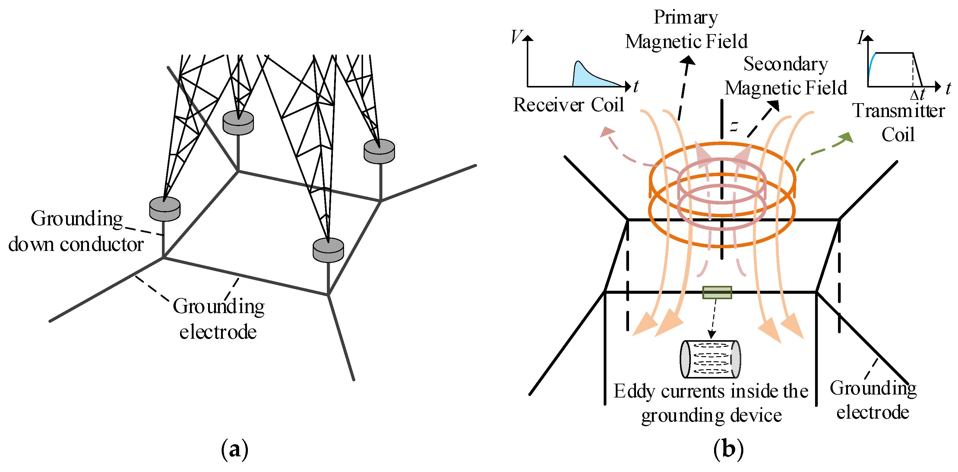
1. Introduction
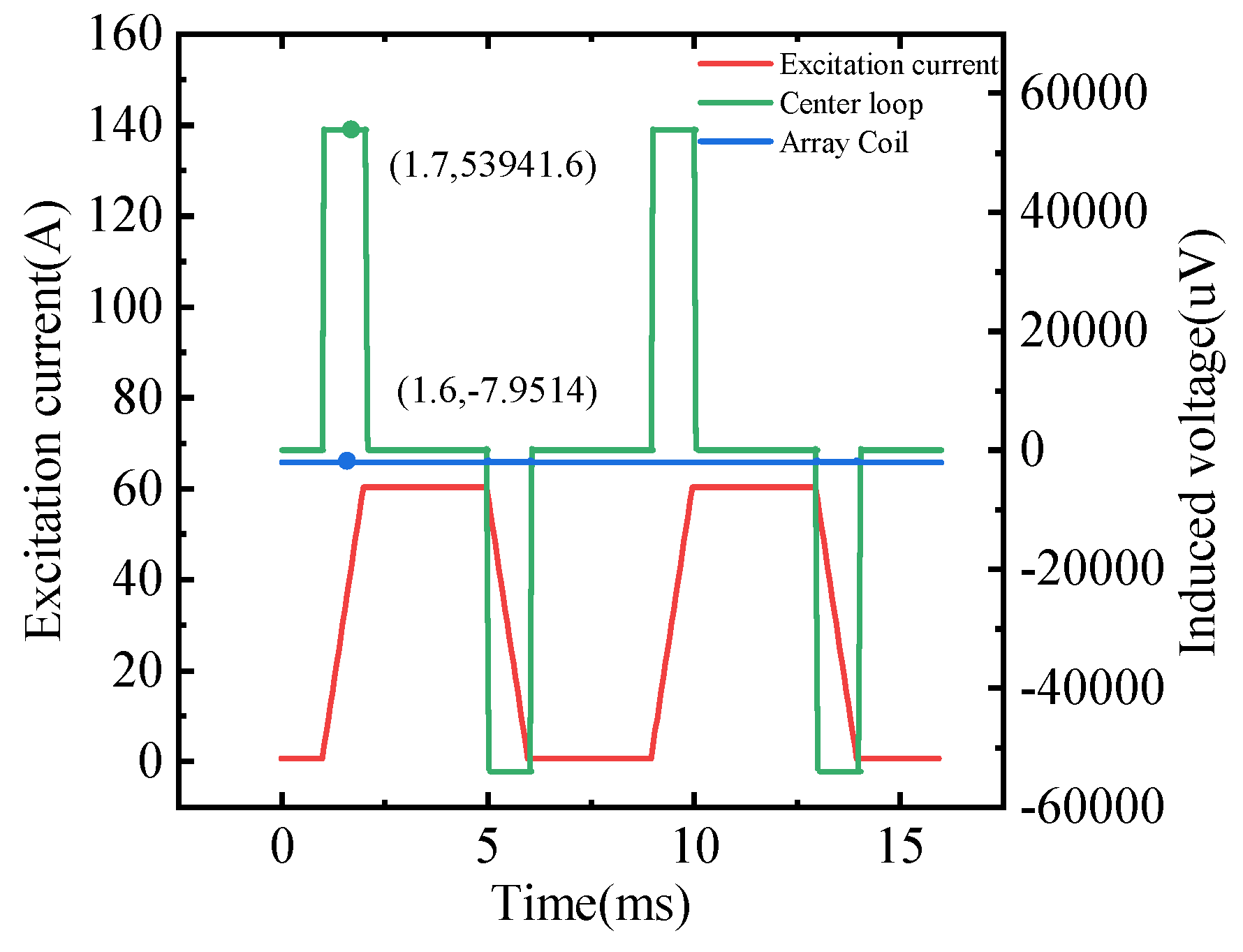
2. Analysis of Aliasing of Excitation and Target Magnetic Field Signals Under Non-Zero Turn-Off Effect
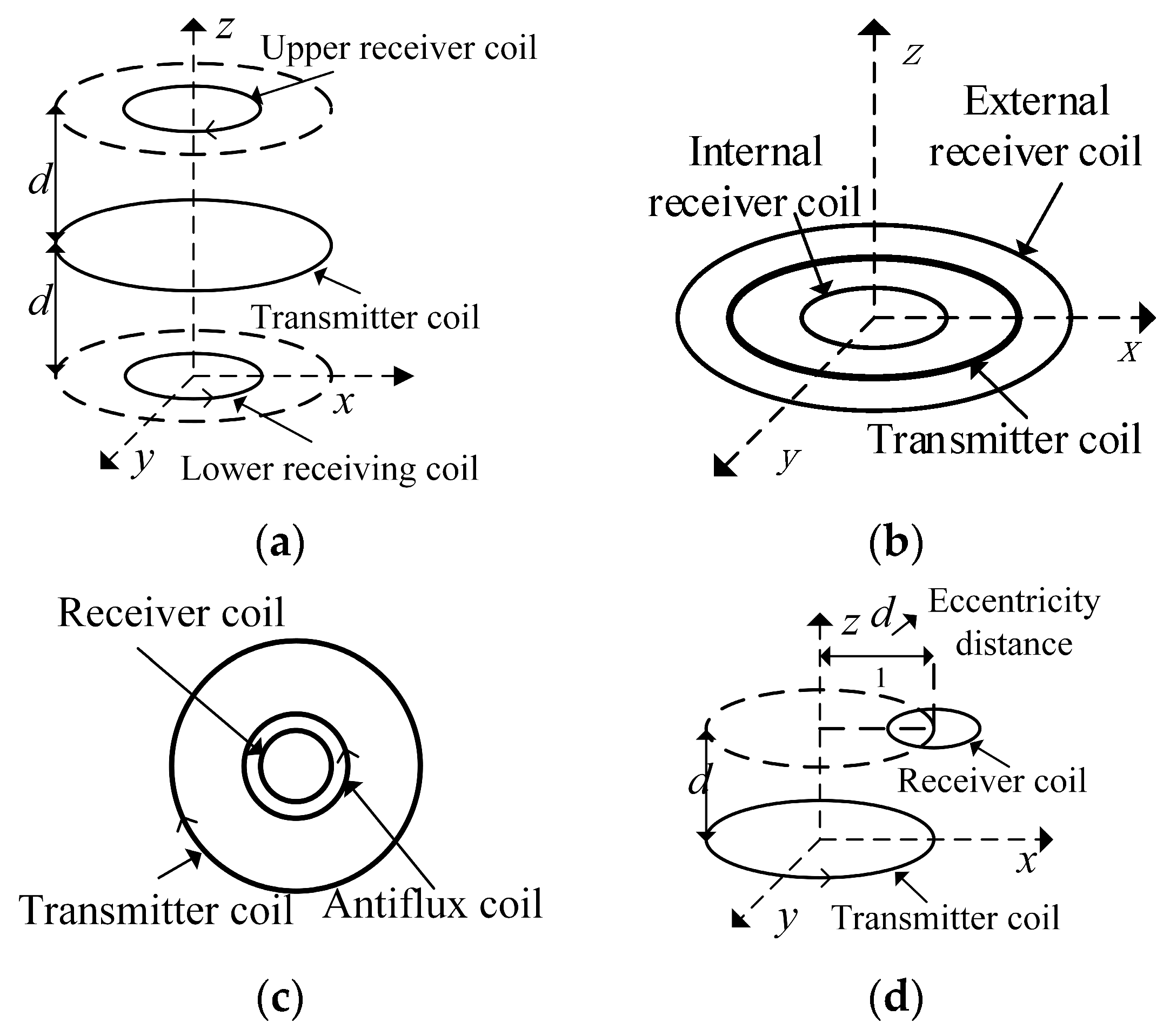
3. Principle of Magnetic Field Vector Destructive Separation and Array Coil Design
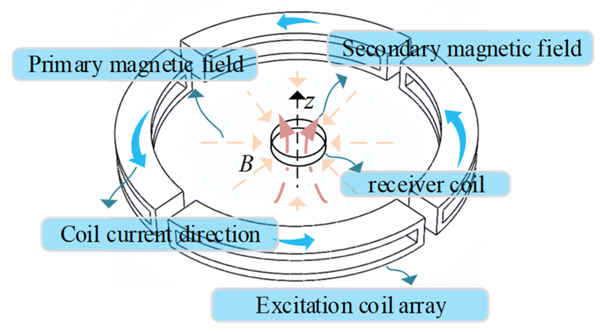
3.1. Principle of Magnetic Field Vector Destructive Separation
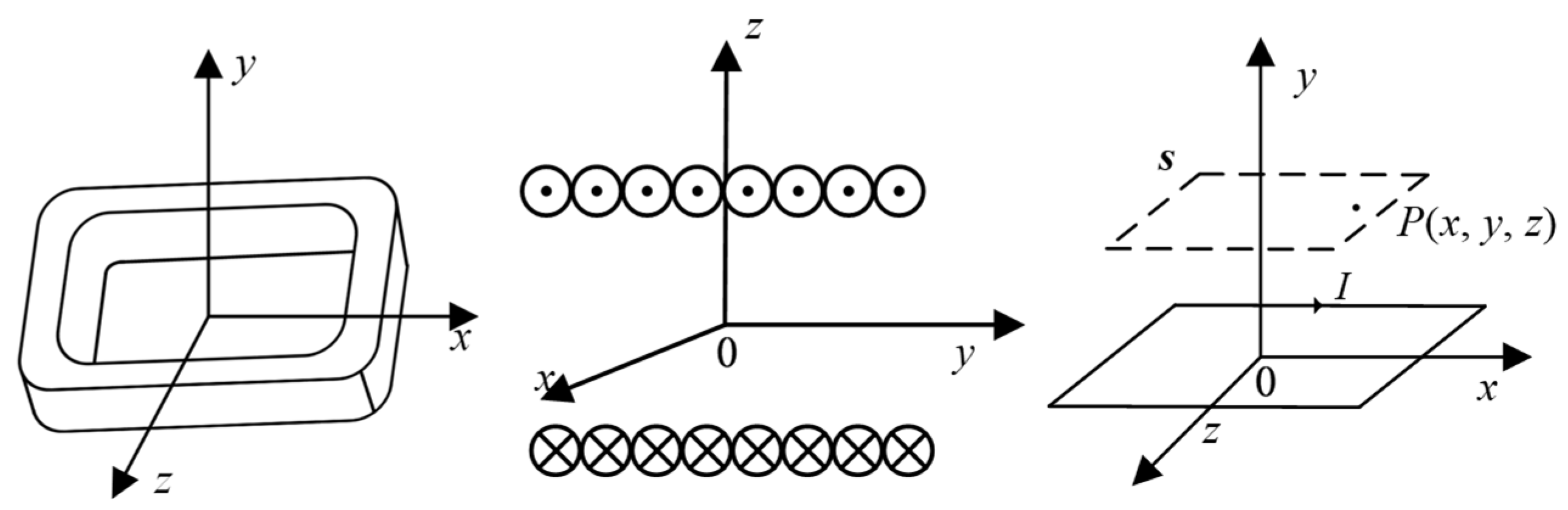
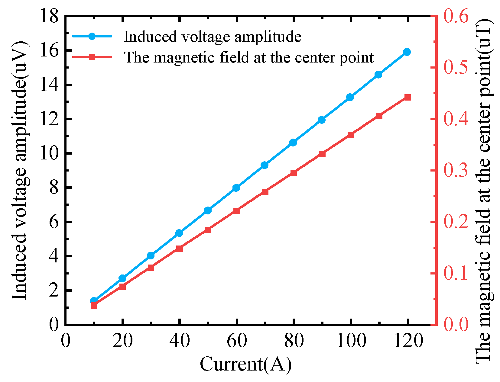
3.2. Static Magnetic Field Distribution and Parameter Simulation Analysis
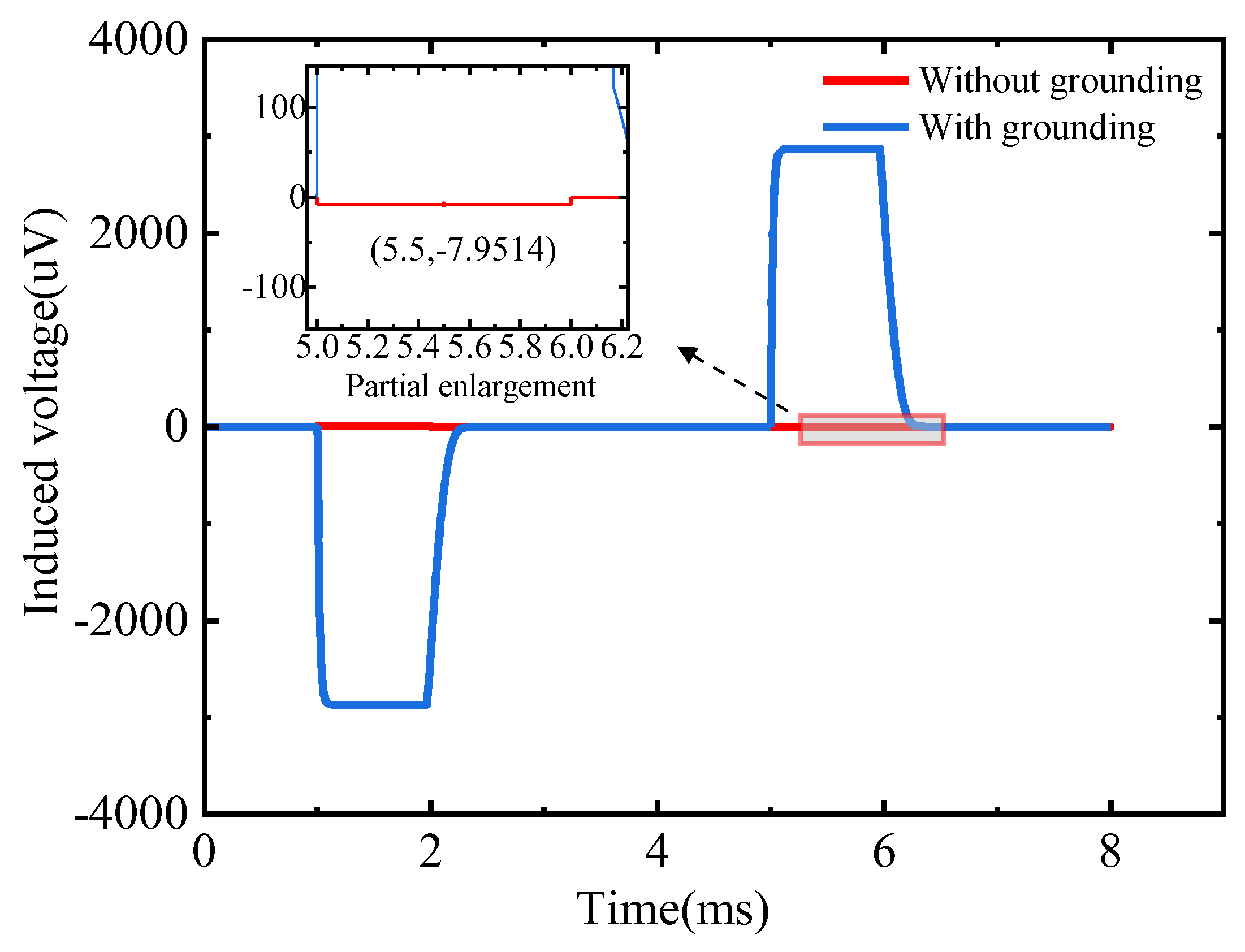
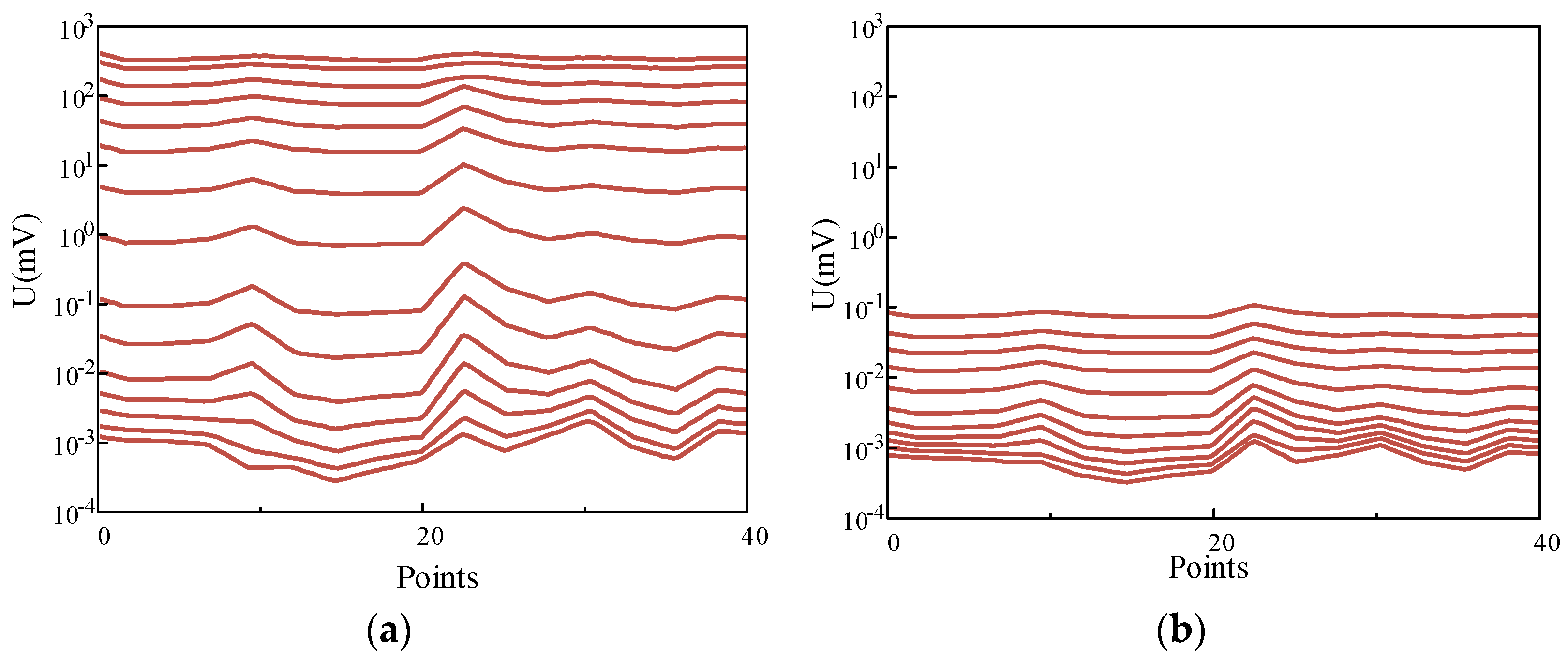
3.3. Grounding Simulation Analysis
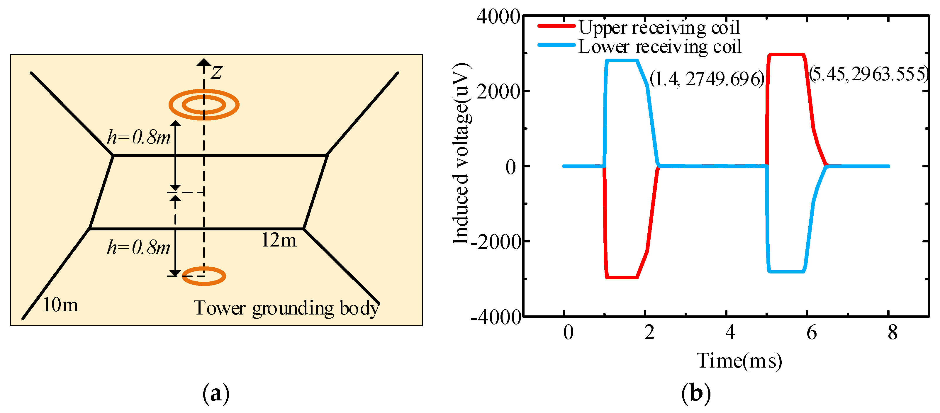
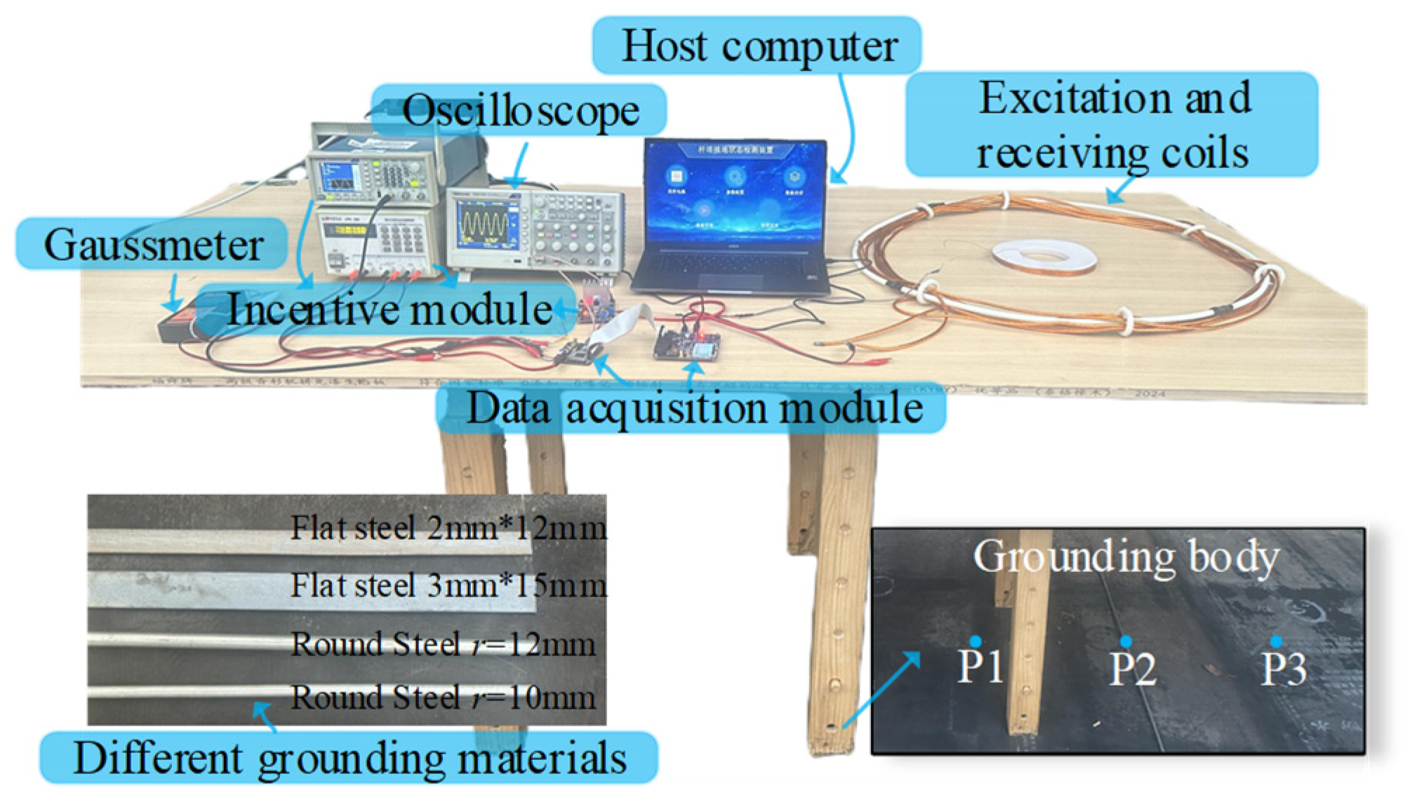
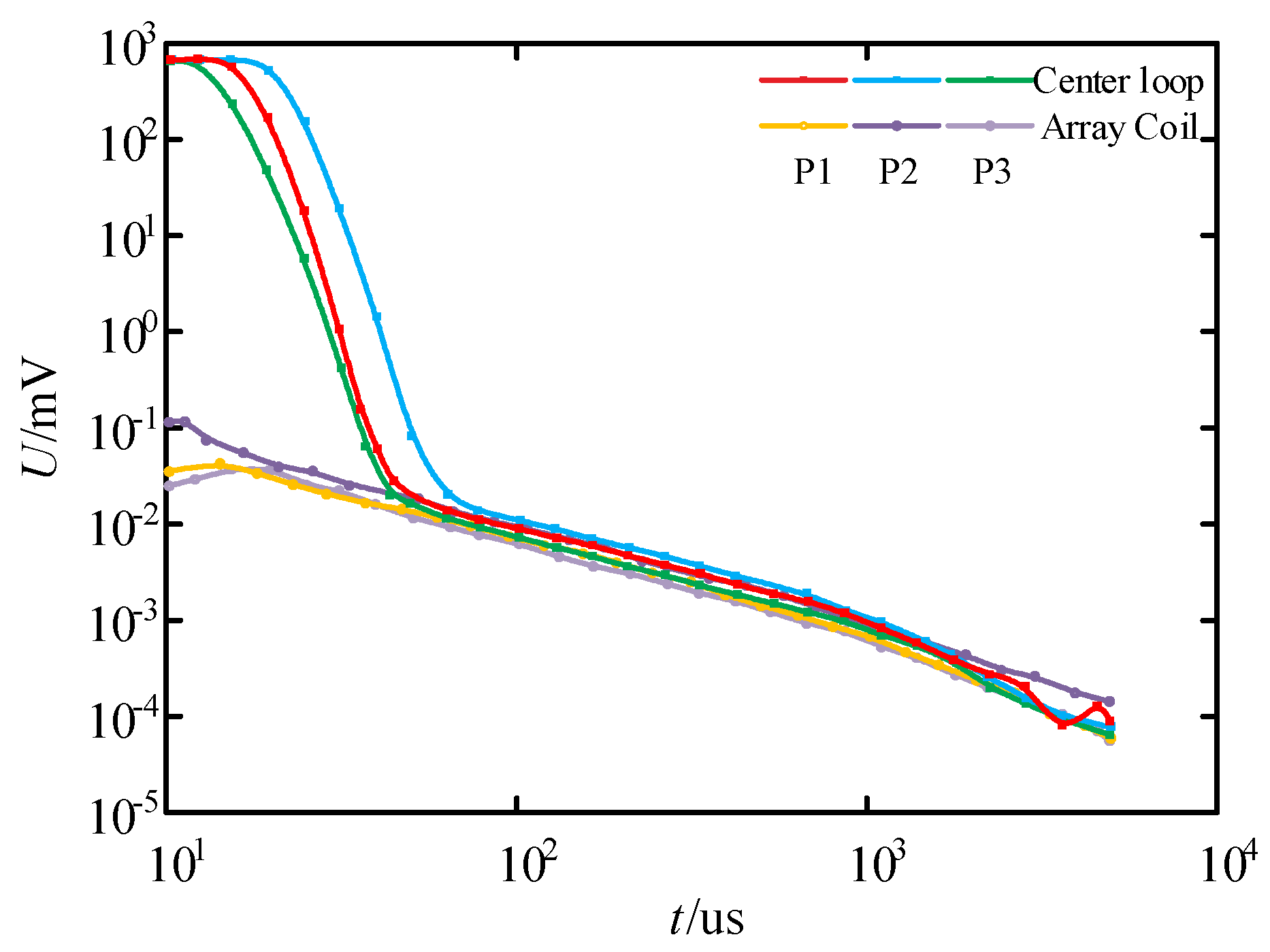
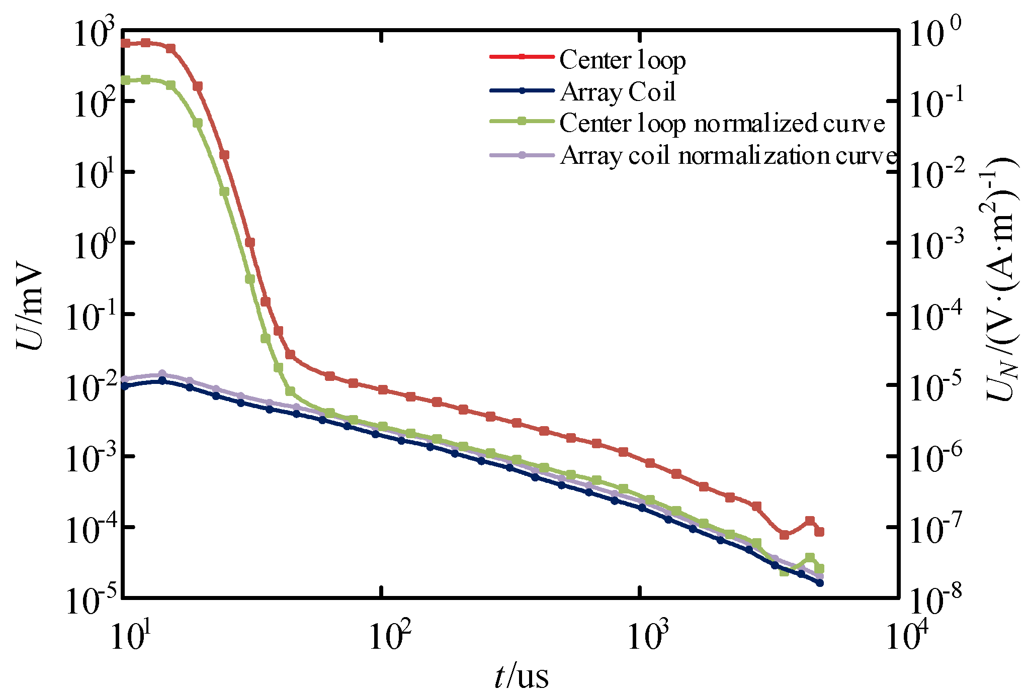
4. Tower Grounding Test
5. Conclusions
- (1)
- Based on the analysis of the principle of magnetic field separation, an array coil design based on magnetic field vector cancellation is proposed on the basis of the existing weak magnetic coupling coil.
- (2)
- Based on numerical analysis, it is proved that the magnetic flux generated by the array coil at the receiving coil is 0, so the decoupling of primary and secondary magnetic fields can be realized.
- (3)
- Based on the simulation analysis, compared with the existing weak magnetic coupling coil structure, it is verified that the array coil structure can greatly reduce the mutual inductance coefficient between the excitation coil and the receiving coil, avoid the influence of the mutual inductance voltage on the received signal, so as to realize the separation of the primary and secondary magnetic fields in the pulsed eddy current testing process and avoid the loss of shallow information.
- (4)
- Finally, by conducting experiments at different measuring points compared with the conventional central loop coil, it is proved, from the angle of detection signal and induced voltage profile, that the array coil can significantly reduce the interference of the primary magnetic field on the received signal, improve the effective resolution time, solve the shallow information loss under the early delay signal, and provide device support for the subsequent actual detection.
Author Contributions
Funding
Data Availability Statement
Conflicts of Interest
References
- Liao, X.; Xu, Z.; Liu, W.; Hu, X.; Zhou, J.; Fu, Z. Influence of Parasitic Capacitance on Turn-off Current and its Optimization Method for Transient Electromagnetic System. IEEE Trans. Instrum. Meas. 2023, 73, 6000311. [Google Scholar] [CrossRef]
- Li, Y.; Tian, G.Y.; Simm, A. Fast analytical modelling for pulsed eddy current evaluation. NDT E Int. 2008, 41, 477–483. [Google Scholar] [CrossRef]
- Yang, J.; Jiang, Z.; Shu, S.; Hu, Y.; Su, X.; Liu, W. Research on grounding characteristics and influencing factors of fractal extension grounding grid of transmission line tower. Smart Electr. Power 2023, 51, 1–8, 38. [Google Scholar]
- Yao, Z.; Yang, X.; Jiangm, L.; Wu, W.; Wang, Y.; Tang, X. Single-phase line installation method of parallel gap in 35 kV overhead line. J. Electr. Power Sci. Technol. 2023, 38, 241–251. [Google Scholar] [CrossRef]
- Arjun, V.; Sasi, B.; Rao, B.P.C.; Mukhopadhyay, C.; Jayakumar, T. Optimisation of pulsed eddy current probe for detection of sub-surface defects in stainless steel plate. Sens. Actuators A Phys. 2015, 226, 69–75. [Google Scholar] [CrossRef]
- Huang, S.; Fu, Z.; Wang, Q.; Zhu, X.; Qin, S. Service Life Estimation for the Small- and Medium-Sized Earth Grounding Grids. IEEE Trans. Ind. Appl. 2015, 51, 5442–5451. [Google Scholar] [CrossRef]
- Yu, C.; Fu, Z.; Wu, G.; Zhou, L.; Zhu, X.; Bao, M. Configuration detection of substation grounding grid using transient electromagnetic method. IEEE Trans. Ind. Electron. 2017, 64, 6475–6483. [Google Scholar] [CrossRef]
- Zhao, P.; Wang, J.; Xia, H.; He, W. A Novel Industrial Magnetically Enhanced Hydrogen Production Electrolyzer and Effect of Magnetic Field Configuration. Appl. Energy 2024, 367, 123402. [Google Scholar] [CrossRef]
- Sophian, A.; Tian, G.; Fan, M. Pulsed Eddy Current Non-Destructive Testing and Evaluation: A Review. Chin. J. Mech. Eng. 2017, 30, 500–514. [Google Scholar] [CrossRef]
- Ida, N. Eddy Current Nondestructive Evaluation—The Challenge of Accurate Modeling. In Proceedings of the 2014 International Conference on Development and Application Systems (DAS), Suceava, Romania, 15–17 May 2014; pp. 97–102. [Google Scholar]
- Xu, Z.; Fu, Z.; Fu, N. Firefly Algorithm for Transient Electromagnetic Inversion. IEEE Trans. Geosci. Remote Sens. 2022, 60, 5901312. [Google Scholar] [CrossRef]
- Xu, Z.; Liao, X.; Liu, L.; Fu, N.; Fu, Z. Research on Small-Loop Transient Electromagnetic Method Forward and Nonlinear Optimization Inversion Method. IEEE Trans. Geosci. Remote Sens. 2023, 61, 5901913. [Google Scholar] [CrossRef]
- Smith, R.S.; Balch, S.J. Robust estimation of the band-limited inductive limit response from impulse-response TEM measurements taken during the transmitter switch-off and the transmitter off-time: Theory and an example from Voisey’s Bay, Labrador, Canada. Geophysics 2000, 65, 476–481. [Google Scholar] [CrossRef]
- Xi, Z.; Long, X.; Huang, L.; Zhou, S.; Song, G.; Hou, H.; Chen, X.; Wang, L.; Xiao, W.; Qi, Q. Opposing-coils transient electromagnetic method focused near-surface resolution. Geophysics 2016, 81, E279–E285. [Google Scholar] [CrossRef]
- Hu, X.; Chen, R.; Zhang, P.; Wu, R.; Fu, M.; Zhou, H. Development and experiment of transient electromagnetic common center zero flux coil. J. China Coal Soc. 2023, 48, 918–930. [Google Scholar] [CrossRef]
- Sun, S.; Peng, L.; Shang, X.; Lin, J.; Ju, C. A system design for improving the waveform of transient electromagnetic emission current. Electr. Meas. Instrum. 2017, 54, 89–93, 115. [Google Scholar]
- Han, Z. Development of Multi-Turn Coil Fast Shut-Off Transient Electromagnetic Transmitter Based on Segmented Discharge Technology. Master’s Thesis, Jilin University, Changchun, China, 2019. [Google Scholar]
- Fu, Z.; Wang, H.; Wang, Y.; Fu, N.; Tai, H.-M.; Qin, S. Elimination of mutual inductance effect for small-loop transient electromagnetic devices. Geophysics 2019, 84, E143–E154. [Google Scholar] [CrossRef]
- Auld, B.A.; Moulder, J.C. Review of Advances in Quantitative Eddy Current Nondestructive Evaluation. J. Nondestruct. Eval. 1999, 18, 3–36. [Google Scholar] [CrossRef]
- Sha, J.; Fan, M.; Cao, B.; Liu, B. Noncontact and Nondestructive Evaluation of Heat-Treated Bearing Rings Using Pulsed Eddy Current Testing. J. Magn. Magn. Mater. 2021, 521, 167516. [Google Scholar] [CrossRef]
- Nabighian, M.N. Electromagnetic Methods in Applied Geophysics; Society of Exploration Geophysicists: Tulsa, OK, USA, 1987; pp. 402–431. [Google Scholar]
- Ding, Z. Optimal Design and Application of Grounding Poles for Transmission Line Towers. Master’s Thesis, China University of Mining and Technology, Xuzhou, China, 2022. [Google Scholar]


| Parameter Type | Mutual Inductance Coefficient M | The Self-Inductance of the Excitation Coil L |
|---|---|---|
| Centre loop | 25.053019 nH | 1.274347 μH |
| Array Coils | 2.394972 pH | 1.341747 μH |
| Differential Structure | 32.8239 pH | 1.33904 μH |
| Eccentric Coil Design | 8.954271 nH | 1.271265 μH |
| Co-centered Zero Flux Coils | 5.55672 nH | 1.34873 μH |
Disclaimer/Publisher’s Note: The statements, opinions and data contained in all publications are solely those of the individual author(s) and contributor(s) and not of MDPI and/or the editor(s). MDPI and/or the editor(s) disclaim responsibility for any injury to people or property resulting from any ideas, methods, instructions or products referred to in the content. |
© 2025 by the authors. Licensee MDPI, Basel, Switzerland. This article is an open access article distributed under the terms and conditions of the Creative Commons Attribution (CC BY) license (https://creativecommons.org/licenses/by/4.0/).
Share and Cite
Zeng, Z.; Guo, Z.; Gan, F.; Zuo, Y.; Tian, X.; Wang, X.; Lin, Z.; Zhu, W.; Wang, X.; Wang, J. Array Coil Design and Experimental Verification for Separation of Tower Grounding Pulsed Eddy Current Excitation and Response Magnetic Field Signals. Energies 2025, 18, 364. https://doi.org/10.3390/en18020364
Zeng Z, Guo Z, Gan F, Zuo Y, Tian X, Wang X, Lin Z, Zhu W, Wang X, Wang J. Array Coil Design and Experimental Verification for Separation of Tower Grounding Pulsed Eddy Current Excitation and Response Magnetic Field Signals. Energies. 2025; 18(2):364. https://doi.org/10.3390/en18020364
Chicago/Turabian StyleZeng, Zhiwu, Zheng Guo, Fan Gan, Yun Zuo, Xu Tian, Xinxun Wang, Zhichi Lin, Wanyi Zhu, Xiaotian Wang, and Jingang Wang. 2025. "Array Coil Design and Experimental Verification for Separation of Tower Grounding Pulsed Eddy Current Excitation and Response Magnetic Field Signals" Energies 18, no. 2: 364. https://doi.org/10.3390/en18020364
APA StyleZeng, Z., Guo, Z., Gan, F., Zuo, Y., Tian, X., Wang, X., Lin, Z., Zhu, W., Wang, X., & Wang, J. (2025). Array Coil Design and Experimental Verification for Separation of Tower Grounding Pulsed Eddy Current Excitation and Response Magnetic Field Signals. Energies, 18(2), 364. https://doi.org/10.3390/en18020364