Abstract
The fuzzy controller is a popular choice for permanent magnet synchronous motor (PMSM) control systems because of its advantages, such as straightforward design, and no reliance on the precise mathematical model of the motor. But the existing pure PI-like fuzzy control strategy still has some disadvantages, such as poor adaptive ability and large overshooting. This work redevelops the structure and rules of the adaptive fuzzy controller, and proposes and proves an improved adaptive PI-like fuzzy control algorithm for the PMSM system. Firstly, a parallel dual fuzzy controller structure is constructed to facilitate the adaptive adjustment of the “PI-like fuzzy controller”. Secondly, the error acceleration parameter rv(k), which contains the PMSM speed information, is set and normalized to accurately identify the dynamic response stages of the PMSM system. Lastly, an adaptive fuzzy rule table is designed based on the dynamic response waveform of the PMSM system, and the control characterization is analyzed. The simulation and experimental results of the PMSM system show that the improved adaptive PI-like fuzzy controller has a broad dynamic adjustment range, the PMSM can rapidly and smoothly reach the given speed during the startup stage with small overshooting, the speed drop is low when the load is abruptly added, the PMSM system can quickly return to the steady state with a strong adaptive ability, and its dynamic performance indicators surpass those of the PID controller and traditional PI-like fuzzy controller.
1. Introduction
The permanent magnet synchronous motor (PMSM) has a series of advantages, such as compact size, high efficiency, minimal torque fluctuations, high power density, ease of maintenance, etc., and it is commonly used as actuator or electromechanical energy conversion device in industrial fields such as transportation, energy, and mechanical processing [1,2]. The PMSM system generally adopts a classical PID controller. Although the system design is relatively simple and exhibits minimal steady-state error [3], it also has some defects such as large overshoot, slow response speed, and poor adaptive ability; thus, it cannot meet the development needs of high-precision control in some industrial fields, such as electric vehicles, robots, etc. [4,5]. In recent years, modern control strategies have been increasingly applied in the PMSM’s control systems. Among these strategies, sliding mode control [6,7], fuzzy logic control [8,9], adaptive control [10,11], and neural network control [2,12] have gained significant attention and application. Fuzzy control can transform expert experience into practical operations based on fuzzy rules and fuzzy reasoning, and has the characteristic of not relying on the precise mathematical model of the controlled object [13]. As a result, it has been widely used in the control of AC motors. The adaptive fuzzy PID controller currently studied is not a pure fuzzy controller [14,15]. Its fundamental purpose is to adjust the PID parameters in real time through fuzzy control algorithms, while the PID controller still takes on the main control task during the control process. Consequently, it cannot fully exploit the inherent advantages of the fuzzy controller. As a type of 2D fuzzy controller, the PI-like fuzzy controller is characterized with no fixed proportional and integral gains, and has enhanced nonlinearity [13,16]. Reference [17] designed a PI-like fuzzy controller for the motion control of a soft exoskeleton, which enhanced the system’s adaptability to parameter variations in comparison to traditional PID controllers. Reference [18] applied a type of PI-like fuzzy controller to the speed control of a PMSM and conducted a comparative analysis with a conventional sliding mode controller. Simulation results indicated that the fuzzy controller exhibited superior dynamic response performance and enhanced anti-interference capabilities. However, both references [17] and [18] did not provide self-adaptive adjustment mechanisms for the PI-like fuzzy controller.
To more effectively illustrate the strong nonlinear control performance of the fuzzy controller, and to achieve adaptive characteristics, some studies have focused on the online adjustment of various parameters in PI-like fuzzy controllers, such as input or output scaling factors (SFs), membership functions (MFs), and fuzzy rules. The authors of [19] provided a set-point weighting mechanism for real-time adjustment of variables at the input of a fuzzy logic controller (FLC). The results indicated that this controller can reduce overshoot and improve resilience to disturbances, regardless of whether the model is linear or nonlinear. However, the FLC employed for adaptive adjustment is a 1D model, which makes it inadequate in accurately identifying the current response state of the system. The authors of [20] adjusted the output size of a PI-like fuzzy controller by introducing a fuzzy coefficient, and its adaptive mechanism has two input variables, including the system error and the output of another fuzzy controller. Although the authors of [20] increased the dimensionality of the input variables, relying solely on these two input variables only allows one to perform local identification of the system. To address the limitations about identification in [20], reference [21] used a relative rate observer (RRO) to dynamically adjust the equivalent integral and differential factors of a fractional-order fuzzy controller. The simulation results demonstrated that this controller structure enabled the system to achieve smaller overshoots and shorter dynamic response times. In order to overcome the major drawbacks of using the relative rate observer and fuzzy parameter regulator (RRO-FPR) approach, the authors of [22] proposed a new on-line fuzzy regulator structure by adjusting the individual output scaling factors of a PID-type fuzzy controller. The superior control performance of the proposed fuzzy controller has been verified through simulation, but there is still a lack of experimental evidence to prove this point. The authors of [23] applied the RRO to the online tuning of variable-order fractional derivatives in fractional controllers, which improves the system’s tracking and immunity ability by changing the change rate of system’s response. At the end, the effectiveness of the online tuning method was verified through the example of quadcopter position control of an aerial vehicle. It can be seen that this RRO can accurately reflect the speed of the system’s current response, and designers can flexibly utilize it in a variety of control algorithms and applications. The RRO adopted in the current studies [21,22,23] was first proposed by M. Guzelkaya in 2003, and few applications in the field of PMSM control have yet been reported. On the basis of [21,22,23], this paper applies the RRO to the speed regulation process of the PMSM control system, constitutes a normalized error acceleration observer (NEAO), and adds some usage instructions to the related calculation formula to make it more relevant to the practical application.
In response to the challenges of slow response speed, significant overshoot, and limited adaptive capability of the surface-mounted PMSM control system, this paper proposes an improved adaptive PI-like fuzzy controller for the PMSM’s speed closed loop. According to the system error e and the normalized error acceleration parameter rv(k), the proposed adaptive PI-like fuzzy controller is able to accurately identify the state of each stage of the system dynamic response. Based on this, global adjustments can be made to the PMSM fuzzy control system, improving the control performance of the PI-like fuzzy controller. Simulation and experimental results show that the improved adaptive PI-like fuzzy controller can effectively improve the dynamic characteristics and anti-interference ability of the PMSM system, and the dynamic adjustment range is wide.
2. Mathematical Modeling of PMSM
This paper takes the surface-mounted PMSM as the study subject. To simplify its mathematical model within the d–q synchronous coordinate system, the following ideal conditions are established:
- (1)
- No regard is given to eddy current losses and hysteresis losses;
- (2)
- The air gap magnetic field of the PMSM is uniform and sinusoidally distributed;
- (3)
- The induced electromotive force in the phase windings is sinusoidal during steady state operation;
- (4)
- The effect of stator cogging is neglected, and the permeability of the permanent magnet is the same as that of air.
Under the above ideal conditions, the PMSM mathematical model can be expressed as follows [2]:
where ud and uq are the d- and q-axis voltage components, respectively; id and iq are the d- and q-axis current components, respectively; Ld and Lq are the d- and q-axis inductance, respectively; Rs is the stator resistance; ψf is the flux linkage of the motor’s permanent magnets; ωm is the rotor’s mechanical angular velocity; ωr is the rotor’s electrical angular velocity, ωr = pnωm; pn is the number of magnetic pole pairs; Te is the motor’s electromagnetic torque; TL is the load torque; and B and J are the friction coefficient and rotor moment of inertia.
3. Fuzzy Adaptive Control System
Figure 1 shows the overall structure of the dual closed-loop control system of the PMSM adopted in this paper, and the control process is as follows: firstly, the speed outer loop uses the proposed improved adaptive PI-like fuzzy controller to obtain the reference value iqref of the q-axis current; secondly, the current inner loop adopts the control mode of idref = 0, and the feedback values of id and iq are obtained from the three-phase currents after Clarke and Park transformation. Subsequently, the deviation of id and iq is fed into the improve adaptive PI-like controller, then by inverse Park transformation for the obtained voltage signals, the reference voltages Uα and Uβ in the stationary two-phase coordinate system are obtained. Finally, by SVPWM processing for the reference voltage signals, the switching signals of the inverter is generated to control the PMSM.
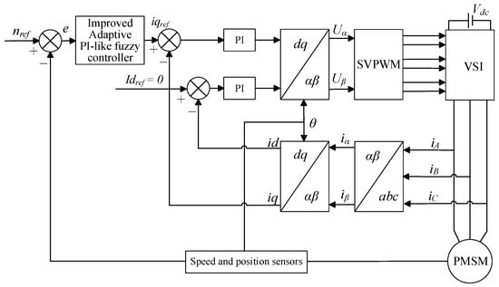
Figure 1.
Structure of PMSM control system.
The proposed improved adaptive PI-like fuzzy controller consists of three parts, i.e., fuzzy controller 1, fuzzy controller 2, and NEAO, as shown in Figure 2. The fuzzy controller 1 is a pure PI-like fuzzy controller; its function is similar to the classical incremental PI controller, and it is used to undertake the main control tasks. Fuzzy controller 2 is an auxiliary fuzzy controller whose control role is to adjust the output of fuzzy controller 1 in real time to improve the adaptability of the PMSM system relative to various stages of dynamic response. The NEAO processes the error acceleration using a normalization algorithm to obtain a state information reflecting the speed of system response. The two fuzzy controllers involved both use the structure of dual-input single-output, so only two different sets of fuzzy rules need to be formulated in the design process, which makes the design process relatively simple.
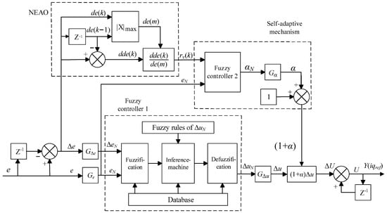
Figure 2.
Structural diagram of improved adaptive PI-like fuzzy controller.
3.1. PI-like Fuzzy Controller
According to the actual requirement of the control accuracy for the PMSM, a total of seven levels of fuzzy sets are selected, including negative large (NB), negative medium (NM), negative small (NS), zero (ZO), positive small (PS), positive medium (PM), and positive large (PB). The fuzzy sets of the input and output quantities (eN, ∆eN, ∆uN) of fuzzy controller 1 are defined as {NB, NM, NS, ZO, PS, PM, PB}, while the shapes of the MFs are all in the form of symmetric, uniformly distributed, semi-overlapping triangles with a normalized “universe of discourse” (UOD) of [−1, 1]. For fuzzy controller 1, the input scaling factors Ge, GΔe, and the output scaling factor GΔu all need to be determined according to the dynamic ranges [emin, emax], [Δemin, Δemax], and [Δumin, Δumax] of actual system, and the regularization formulae for the input and output UOD are as follows [24]:
During the speed control of the PMSM, due to the equal amplitude of the upper and lower limits of the dynamic range in which the system actually operates, Equation (2) can be simplified as follows [13]:
It is worth noting that, unlike the PD-like fuzzy controller, the output ΔuN of the PI-like fuzzy controller (fuzzy controller 1) in this paper corresponds to the increment required for the system output at the current moment, and its fuzzy rule table is shown in Table 1.

Table 1.
Fuzzy rules for ΔuN.
In order to obtain the output of the refined fuzzy controller, the fuzzified output is obtained according to Mamdani’s min–max inference method and defuzzied using the center of gravity method, which is calculated as follows [13]:
3.2. Selection of Observation Quantities for Self-Adaptive Mechanisms
Usually, the error e and the error change Δe are selected as the observation quantities at the input of the adaptive adjustment mechanism, but these two can only locally observe the working state of the system at a certain point; they cannot globally reflect the dynamic response of the system. As shown in Figure 2, NEAO takes Δe as the input variable, and the normalized error acceleration rv(k), which can reflect the speed of the system response, can be obtained through simpler conditional discriminations (e.g., the change rule of rv(k) 4) and formula calculations. In order to accurately identify the various dynamic response stages of the system, this paper takes rv(k) and the velocity error e two parameters as the input variables of the self-adjusting mechanism (fuzzy controller 2) [22,23,24].
The normalized error acceleration rv(k) is defined as
In Equation (5), de(k) is the error velocity of the system at moment k, and dde(k) is the error acceleration of the system at moment k; they are defined as follows:
The de(m) in Equation (5) is defined as
In the process of system dynamic response, the relative speed of response can be determined by the size of |de(k)| and |de(k − 1)|. When the positive and negative of de(k) and de(k − 1) are not considered to be the opposite, the following occur: when |de(k)| > |de(k − 1) |, the system responds faster; when |de(k)| < |de(k − 1)|, the system responds slower; when |de(k)| = |de(k − 1)|, the system responds moderately.
The rv(k) expression in Equation (5) is used to provide a quantitative description of how fast or slow the system responds. By bringing Equation (8) into Equation (5), the normalized error acceleration rv(k) can be rewritten as follows:
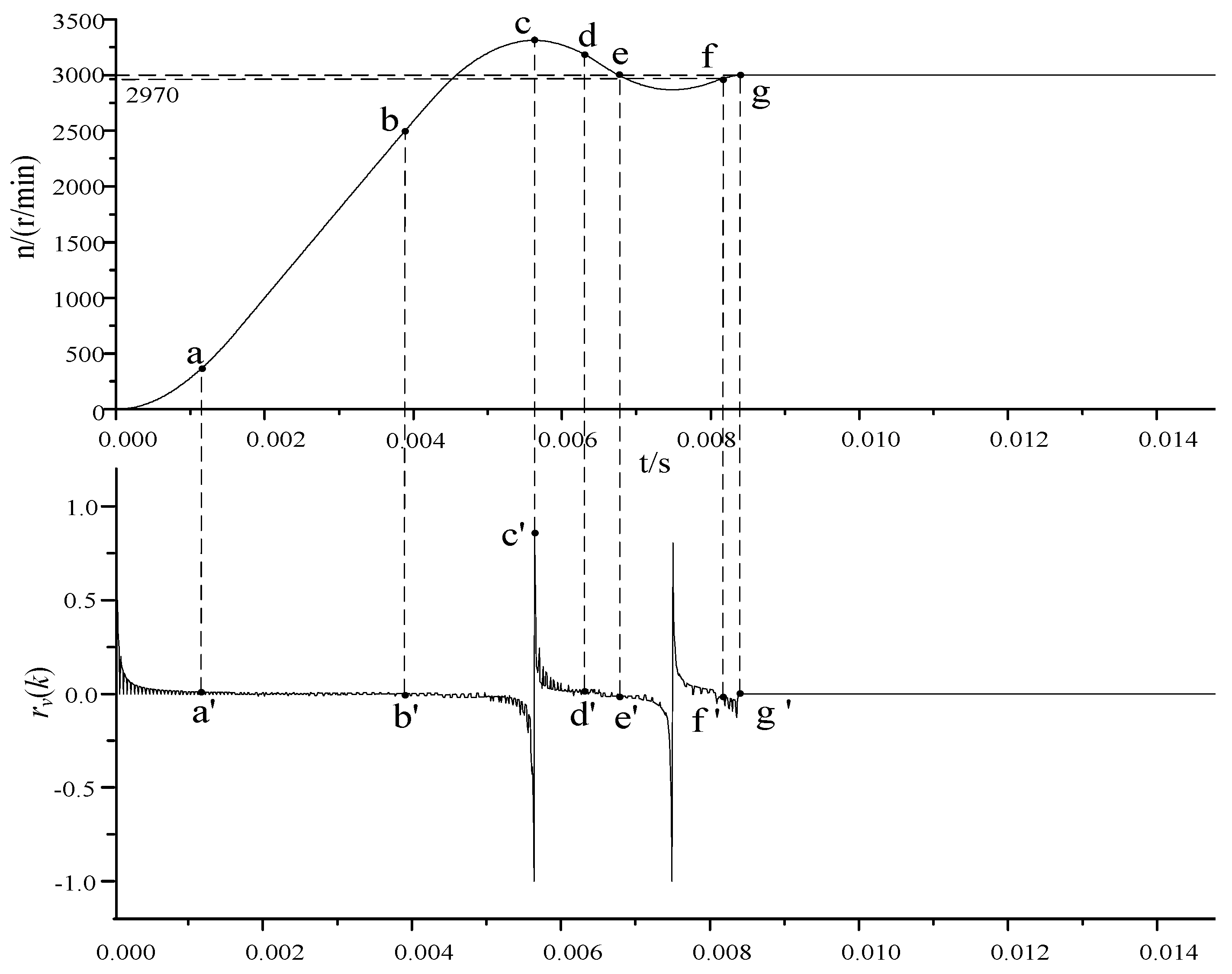
Figure 3 shows the change trend of normalized error acceleration rv(k) following the system response state. By combining Figure 3 and Equation (9), it can be seen that the change rules of rv(k) set in this paper are as follows:
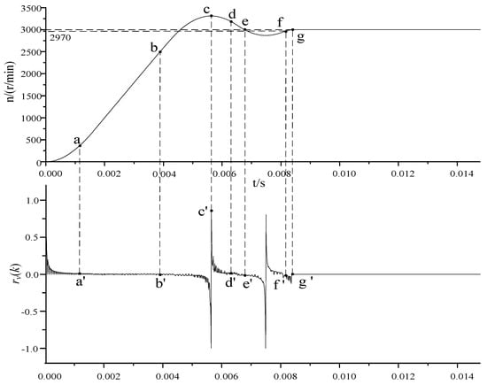
Figure 3.
Waveforms of rv(k) following the dynamic response of the system.
- (1)
- When the system response speed is fast enough, the value of rv(k) is close to 1.
- (2)
- When the system response speed is slow, the value of rv(k) approaches −1.
- (3)
- When the system response speed rises or falls at a certain rate, the value of rv(k) tends to 0.
- (4)
- When the values of de(k) and de(k − 1) are same positive or same negative, and the values of |de(k)| and |de(k − 1)| are not 0 at the same time, the range of rv(k) is [−1, 1].
3.3. Design of Self-Adaptive Mechanisms
Among the various adjustable parameters of FLC (e.g., input and output SFs, fuzzy rules, and MFs), the adjustment of the input and output SFs has the highest priority; the reason is that they have a global impact on the performance of the control system [18,19]. Compared to the input, the output of FLC directly corresponds to the given value of the motor q-axis current, which is directly related to the stability of the system, so the adaptive adjustment of the output SF is extremely important.
As for fuzzy controller 2, the definition of fuzzy subsets of input and output variables, the shape of the scaling factors, the division of the UOD, and the method of inference and defuzzification method remain consistent with the design form of fuzzy controller 1.
The dynamic response stages of the system are divided according to Figure 3, and the design criterions of adaptive fuzzy rules are determined as follows:
- (1)
- 0~a: When the system error is large and the response speed is fast, increase the output of fuzzy controller 2 so that the total output U of the controller increases positively and the system approaches the set value quickly.
- (2)
- b~c: When the system error is small and the response speed is constant or slow, adjust the output of fuzzy controller 2 so that the total output U of the controller decreases to avoid excessive overshooting.
- (3)
- c~d: When the system speed starts to fall back and the response speed is fast, the total output U of the controller should be further reduced to approach the steady state quickly.
- (4)
- d~e: When the system falls back to near the set point and the response speed is constant, fine-tune the output of fuzzy controller 2 so that the total output U of the controller increases in advance and the reverse overshoot is reduced.
- (5)
- e~f: When the system falls back excessively, regardless of the speed of response, adjust the output of fuzzy controller 2 so that the total output U of the controller increases continuously, suppressing the overshoot and speeding up the speed of response.
The designed fuzzy rule table for fuzzy controller 2 based on the above design criterions is shown in Table 2. The adaptive adjustment of fuzzy controller 2 to the output of fuzzy controller 1 is achieved through a self-adjusting factor α. According to Figure 2, αN is the output of fuzzy controller 2, and the self-adjustment factor α is obtained after it is scaled by the output scaling factor Gα, so α is satisfied:
Table 2.
Fuzzy rules for αN.
Combined with Equation (10) and Figure 2, it can be seen that by adjusting the output scaling factor Gα of fuzzy controller 2, the adjustment degree to the output size of fuzzy controller 1 can be changed by the self-adjusting mechanism. On the basis of the appropriate design of fuzzy adaptive rules, if the output scaling factor Gα is too small, the system’s adaptive ability will be insufficient, and if the Gα is too large, there may be too long a time to adjust, the system is unstable, and other problems may occur. Therefore, in the design process of the controller, the selection of the output scaling factor Gα is particularly important for the control performance. During the debugging of the control system, the initial value of Gα can start from a very small value, and then the system can obtain the best dynamic response by gradually increasing the value. In Section 4. “Simulation and Experimental Research” later in this paper, the optimal value of Gα obtained is 0.262.
After the introduction of the self-adjusting mechanism on the basis of the original controller, the output U of the adaptive fuzzy controller corresponding to the current k moments of the system can be expressed as follows:
where G∆u is the output SF of fuzzy controller 1, and G’∆u is the equivalent output factor of fuzzy controller 1.
From Equation (11), it can be seen that through the self-adjustment factor α output by fuzzy controller 2, the equivalent output factor G’∆u of fuzzy controller 1 can be adaptively adjusted according to the system operating state, which in turn changes the size of the system output increment at the moment k and ultimately makes the total output of the controller change dynamically and improves the adaptivity of the system fuzzy controller.
3.4. Performance Analysis of the Improved Adaptive PI-like Fuzzy Controller
In the improved adaptive PI-like fuzzy control algorithm proposed in this paper, by introducing overall gain (1 + α), the online adjustment of adaptive mechanism to the different dynamic response stages of the PMSM system is realized. As the UOD of the output αN of fuzzy controller 2 is normalized, αN ∈ [−1, 1], while according to Equation (10), α ∈ [−Gα, Gα]. Here, |Gα| is the maximum magnitude of the adjustment gain, which is generally chosen as a positive integer of [0, 1]. Finally, the variation range of the overall gain (1 + α) can be obtained as [1 − Gα, 1 + Gα], whereby the control performance of the improved adaptive PI-like controller is classified and discussed into three cases in conjunction with Figure 3. The specific cases are as follows:
- (1)
- Enhanced control stage
When [1 + α(k)] ∈ (1, 1 + Gα], namely, the overall gain [1 + α(k)] > 1, then |ΔuN|(i.e., the absolute value of the output increment ΔuN of the fuzzy controller 1) is amplified. The output increment ΔU’(k) of the improved adaptive PI-like fuzzy controller according to Equation (11) can be expressed as
Denoting the system error variation due to the U’(k) as H(U’(k)), the error dynamic equation of the system is
Similarly, the error dynamic equation of the system when adopting the conventional PI-like fuzzy controller is
Taking the 0~a and c~d stages of the system’s response in Figure 3 as an example, as [1 + α(k)] > 1, then
For the e(k), as H(U’(k)) and H(U’(k)) are all greater than zero values in the 0~a stage and all smaller than zero values in the c~d stage, there is relation equation in these two stages as follows:
From Equation (16), it can be seen that compared to the traditional PI-like controller, the improved adaptive PI-like fuzzy controller is able to eliminate more errors and accelerate the system convergence in each sampling cycle of the system both in 0~a stage and c~d stage of the system dynamic response.
- (2)
- Attenuated control stage
When the overall gain [1 + α(k)] ∈ (1 − Gα, 1), |ΔuN| is contracted. From Equation (11), the output increment ΔU’(k) of the improved adaptive PI-like fuzzy controller at this time can be expressed as
According to Equations (13) and (14) and taking the d~e stage of system response in Figure 3 as an example, as [1 + α(k)] < 1 at this time, there is a relation equation as follows:
In the d~e stage, e(k) < 0, H(U’(k)) < 0, H(U(k)) < 0; thus, we can obtain
From Equation (19), it can be seen that compared with the traditional PI-like controller, in the d~e stage of system dynamic response (close to the system speed set point), the improved adaptive PI-like fuzzy controller is able to slow down the error change, inhibit the speed fallback, and reduce the oscillations in each sampling cycle of the system.
- (3)
- Balance control stage
When the overall gain [1 + α(k)] = 1, |ΔuN| has no change. From Equation (11), the output increment ΔU’(k) of the improved adaptive PI-like fuzzy controller in this case can be expressed as follows:
For example, in the f~g stage of system response, |e(k)| ≤ 30 (where the |e(k)| is the absolute value of system error e(k), the error from the given speed is only less than or equal to 1%, and in this case, no adaptive adjustment is executed, so the system smoothly enters the steady state. In other words, at this time, the improved adaptive PI-like fuzzy controller naturally degenerates into the traditional PI-like fuzzy controller.
Integrating the above analyses, through this dynamic adaptive adjustment mechanism that distinguishes stages, the improved controller is superior to the traditional PI-like fuzzy controller in error convergence speed and control effect.
4. Simulation and Experimental Research
4.1. Simulation Research
In order to verify the validity and superiority of the proposed improved adaptive PI-like fuzzy control algorithm, the control model of the PMSM speed control system is built in the MATLAB R2022b/Simulink simulation environment. The parameters of the experimental PMSM are shown in Table 3.
Table 3.
Parameters of the surface-mounted PMSM.
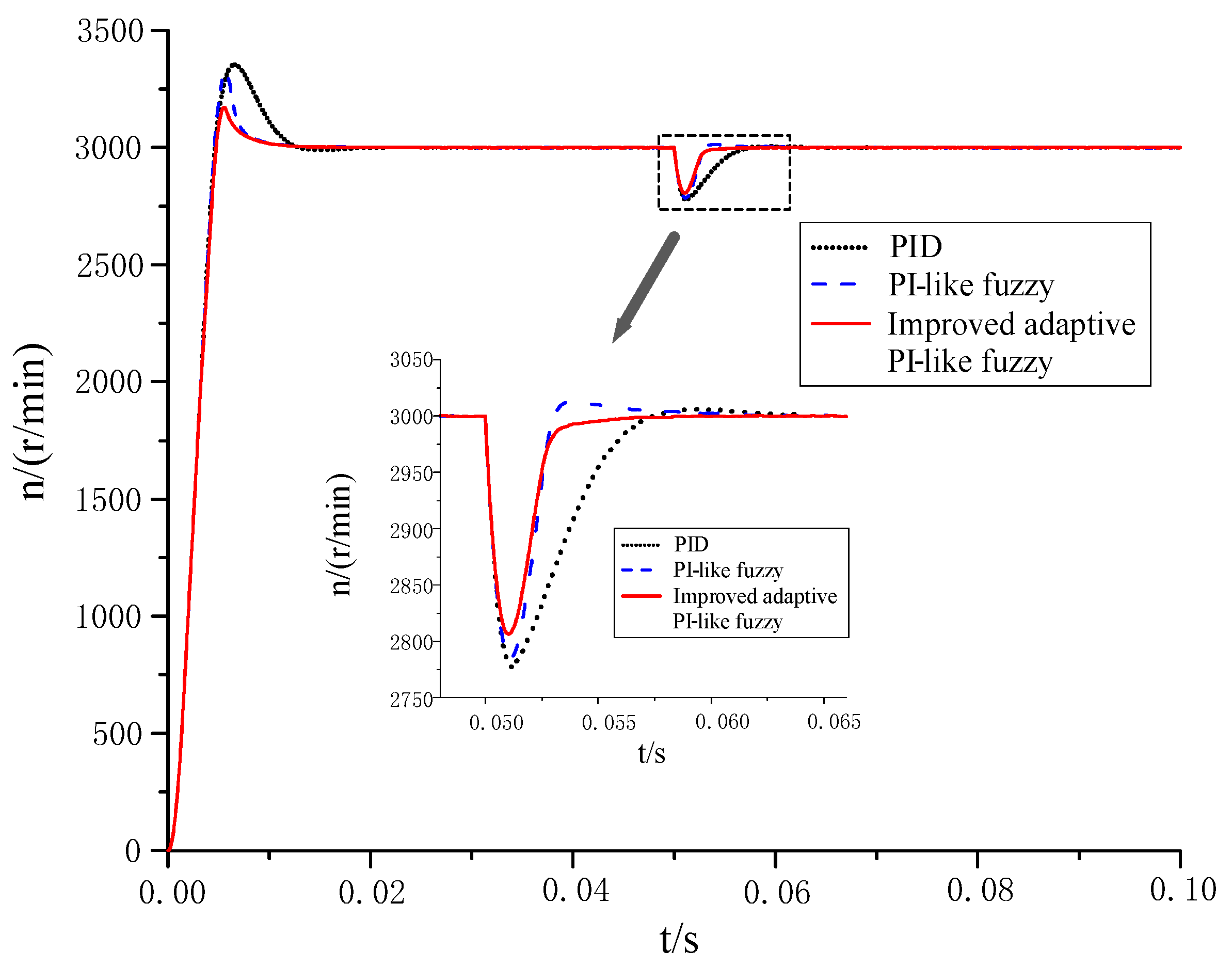
The simulation conditions are set as follows: the given speed is 3000 r/min, the simulation time is 0.1 s, and the rated 1.27 N load is applied at t = 0.05 s. Under the same working conditions, Figure 4 shows the dynamic response waveforms of the PMSM system when the improved adaptive PI-like fuzzy controller is used. For the sake of comparison, Figure 4 also shows the comparative waveforms of the control effect of the system using the traditional PID controller and PI-like fuzzy controller. According to the comparative response waveforms in Figure 4, there are the following research results:
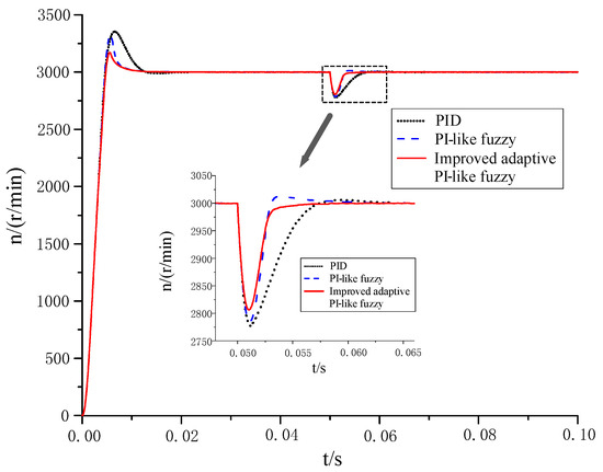
Figure 4.
Dynamic response waveform diagram of PMSM system.
- (1)
- In the start-up stage of the PMSM system, when the improved adaptive PI-like fuzzy control algorithm is adopted, the overshoot of the system is obviously the smallest, about 5.7%, and the time to steady state is the shortest, about 0.007 s. Compared with the PID control system, the PI-like fuzzy control system has a smaller adjustment time: the former is about 0.0075 s, and the latter is about 0.012 s, but the overshoots of the two systems are not much different: the PID control is 11.8%, and the PI-like fuzzy is 10.5%.
- (2)
- When the PMSM system is loaded suddenly, the improved adaptive PI-like fuzzy control system of the PMSM has the least dynamic speed drop, about 6.4%, and the shortest recovery time to the given speed about 0.0035 s. The recovery time of the PI fuzzy control system of the PMSM is about 0.0045 s, which is not very different to that of the improved adaptive PI-like fuzzy control system, but it has significantly more dynamic speed drop, about 7.2%, and the stability is worse. The PID control system of the PMSM has the worst anti-interference ability: the dynamic speed drop and system recovery time are about 7.4% and 0.007 s, respectively.
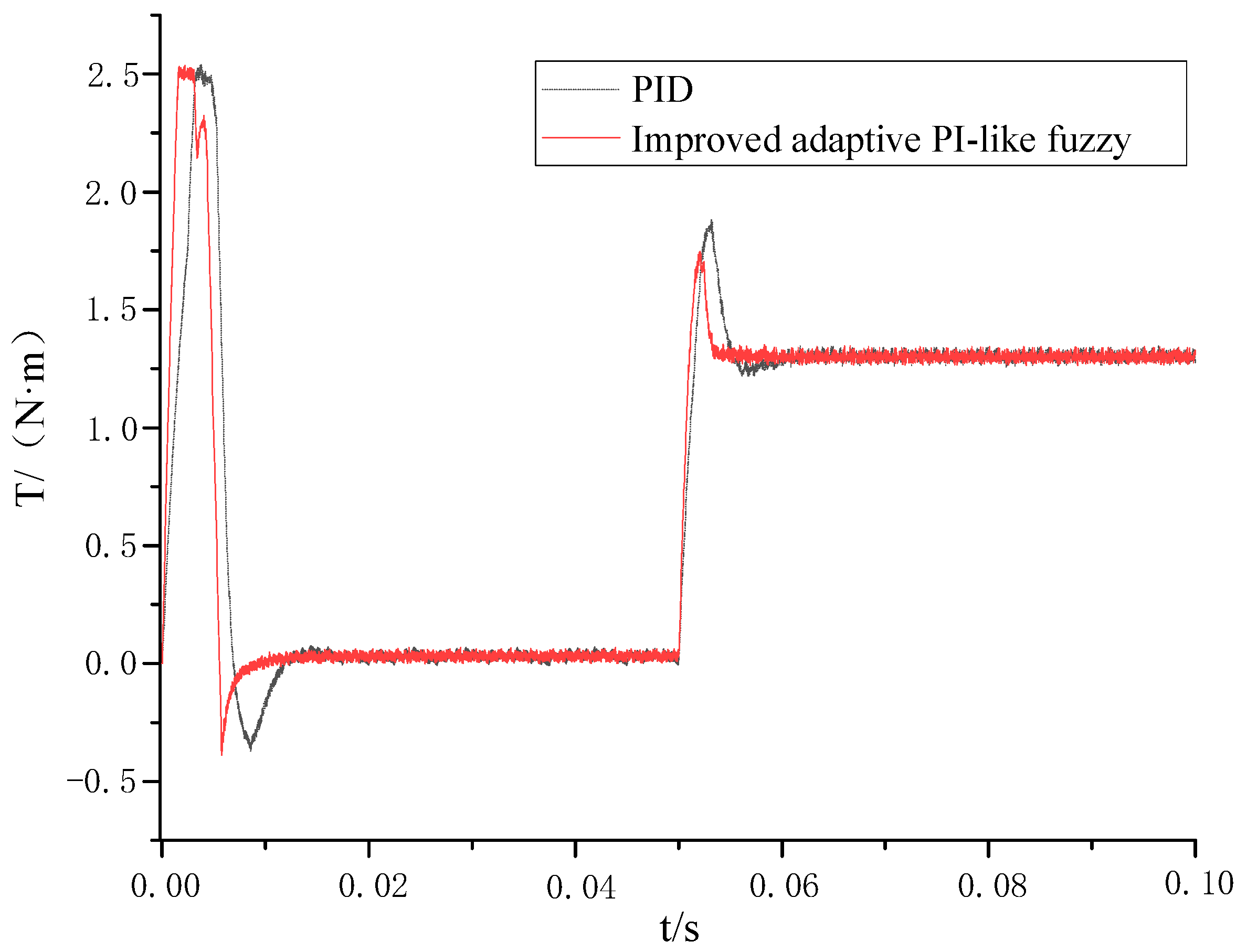
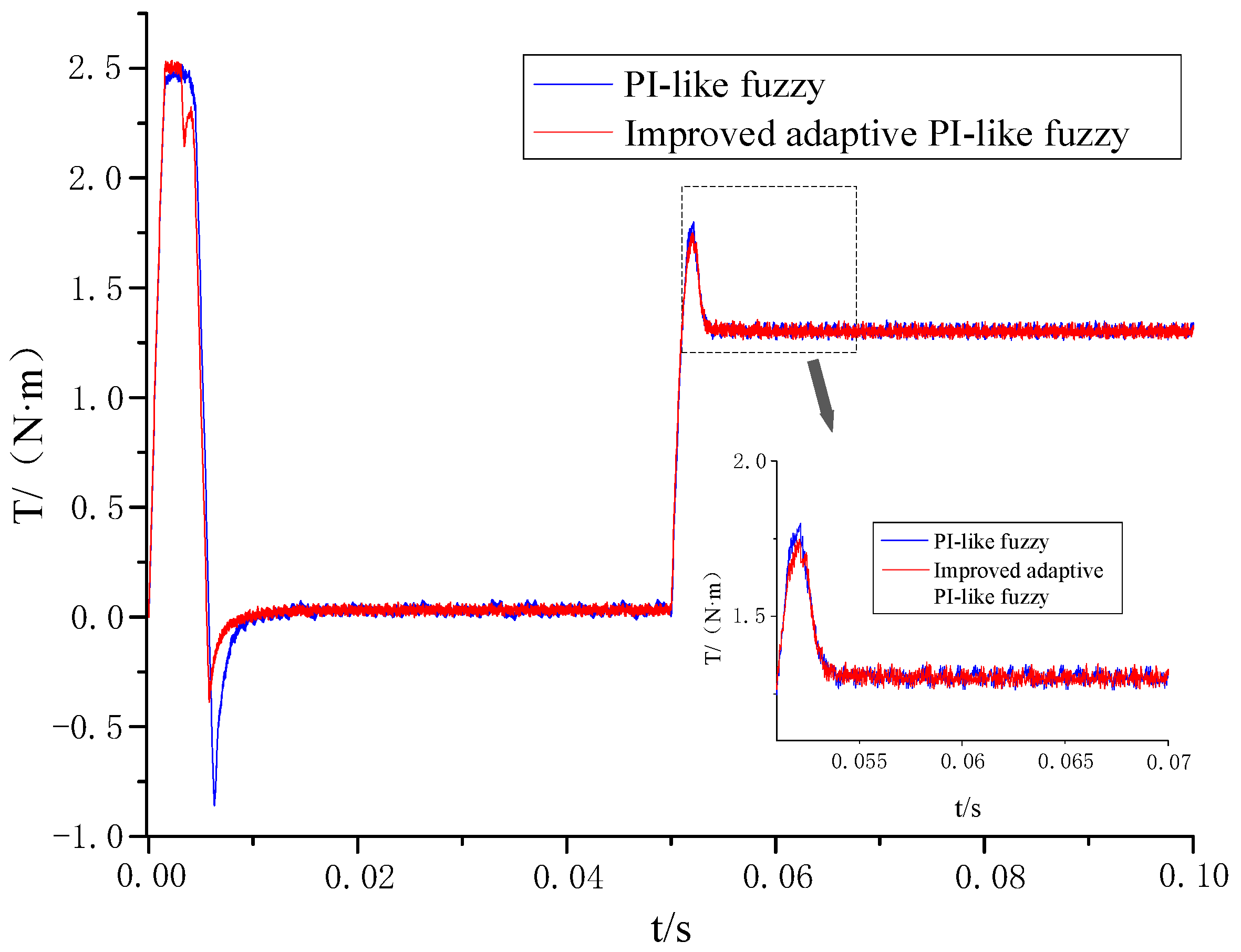
Figure 5 and Figure 6 show the comparison waveforms of the torque response during the dynamic response of the PMSM system, and it can be seen that, compared with the PID controller and the PI-like fuzzy controller, when the improved adaptive PI-like fuzzy controller proposed in this paper is used, the faster torque response can be obtained regardless of whether in the start-up stage of the PMSM system or when the load is added suddenly; the PMSM system can reach the stabilization state more quickly, and then the PMSM system has better stability.

Figure 5.
Comparison of torque response waveforms between PID control and improved adaptive PI-like fuzzy control.
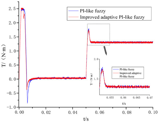
Figure 6.
Comparison of torque response waveforms between conventional PI-like fuzzy control and improved adaptive PI-like fuzzy control.
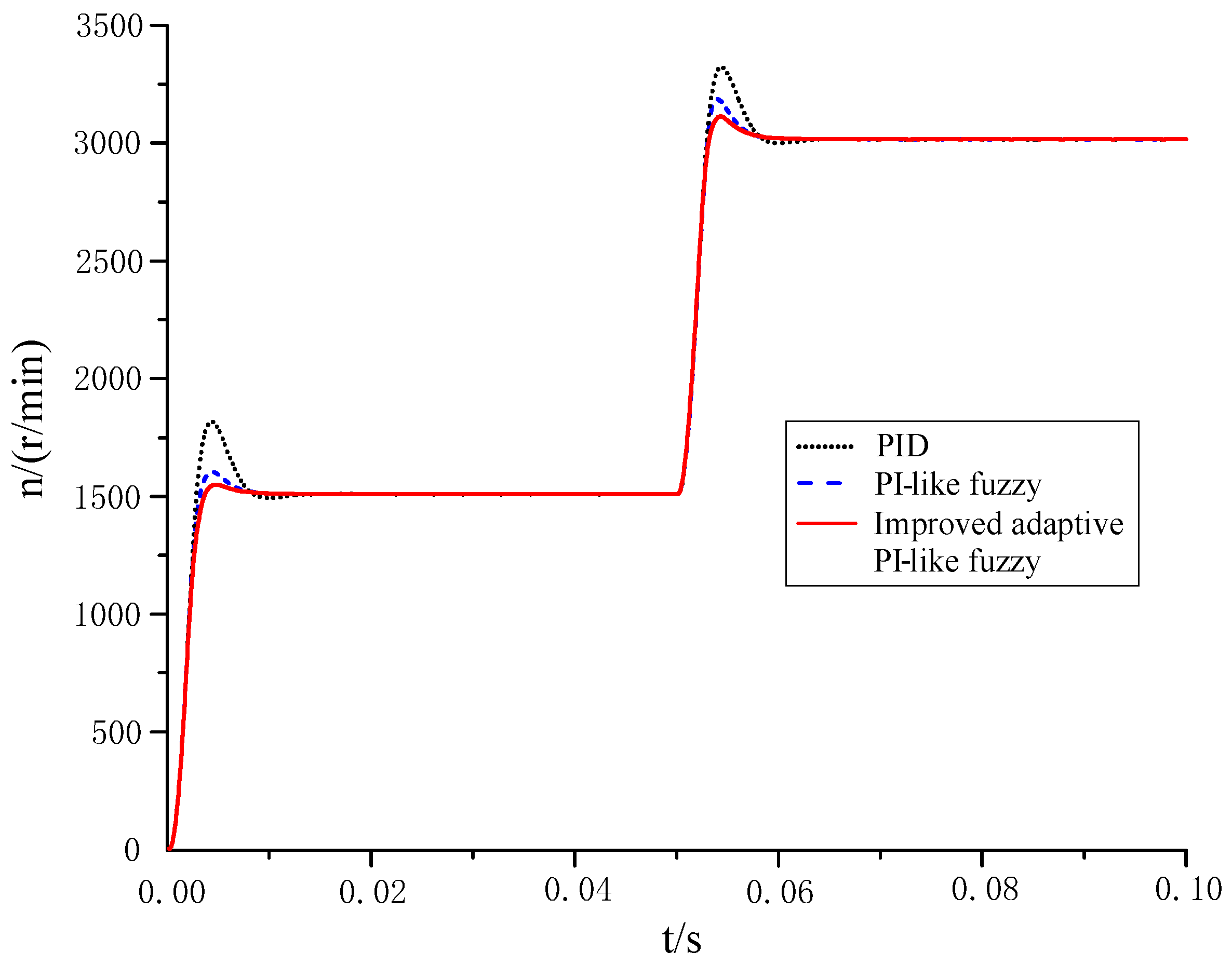
In order to further compare the speed control characteristics of the PMSM system when three different controllers are used, the simulation experimental conditions are modified as follows: the simulation time is 0.1 s, the given speed is 1500 r/min at t = 0.05 s, and the sudden change of the speed is 3000 r/min at t = 0.05 s. Figure 7 shows the dynamic response waveforms of the system, and Table 4 shows a comparison of the performance parameters of the PMSM system when three different controllers are used.
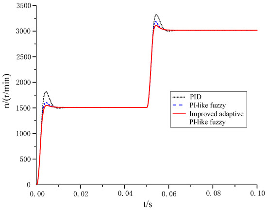
Figure 7.
Speed regulation response waveform of PMSM.
Table 4.
Performance comparison of three controllers.
From Figure 7 and Table 4, it can be seen that when the given speed of the PMSM system undergoes a step change at different moments, the use of the improved adaptive PI-like fuzzy controller enables the PMSM system to obtain the relatively optimal dynamic response characteristics, which can minimize the system overshoot and regulation time.
4.2. Experimental Research
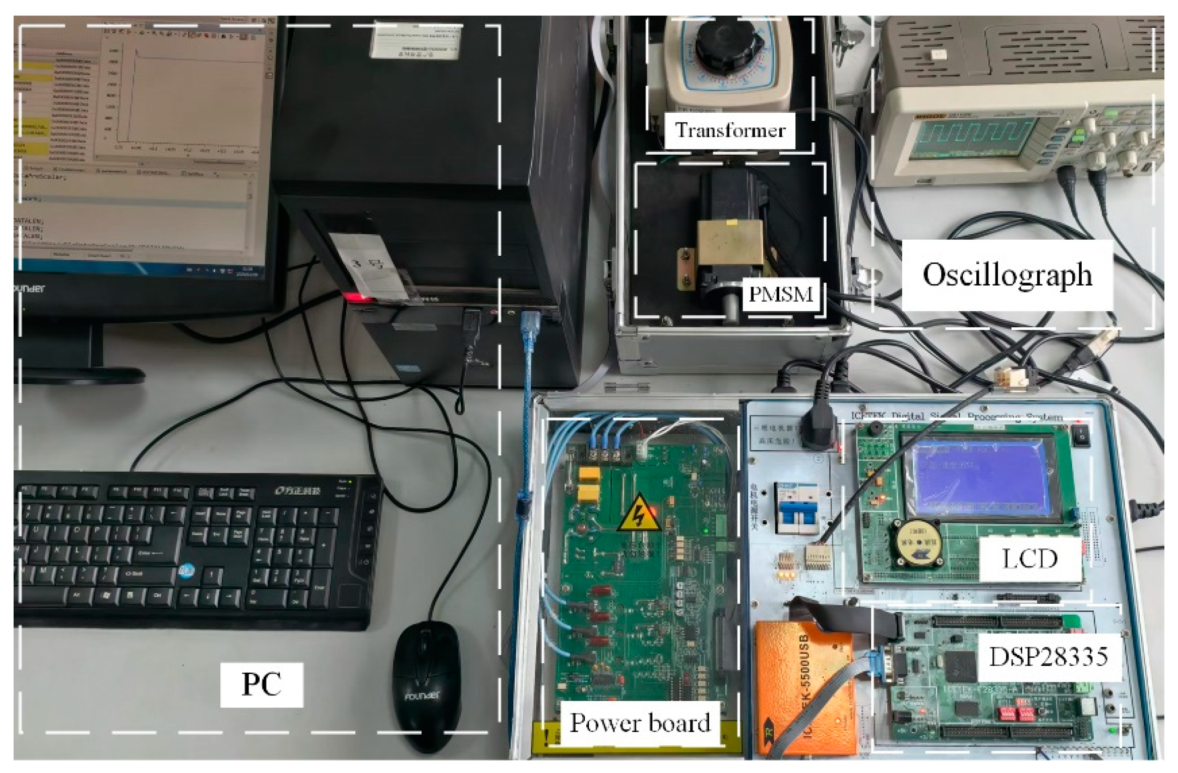
In order to further verify the validity of the proposed control algorithm, the experimental platform of the PMSM control system is built as shown in Figure 8. The parameters of the experimental PMSM utilized in the experiment are consistent with those of the simulated motor (Section 4.1), as shown in Table 3. The controller adopts the DSP controller TMS320F28335 produced by Texas Instruments (Dallas, TX, USA), the software development environment is Code Composer Studio (CCS) 7.4.0, and the control code is written in C language. The sampling frequency of the current loop and that of the speed loop are 10 kHz and 2 kHz, respectively; both fuzzy controllers involved are implemented using the look-up table method; and more output data are obtained by linear interpolation to obtain a continuous output waveform.

Figure 8.
PMSM control system experimental bench.
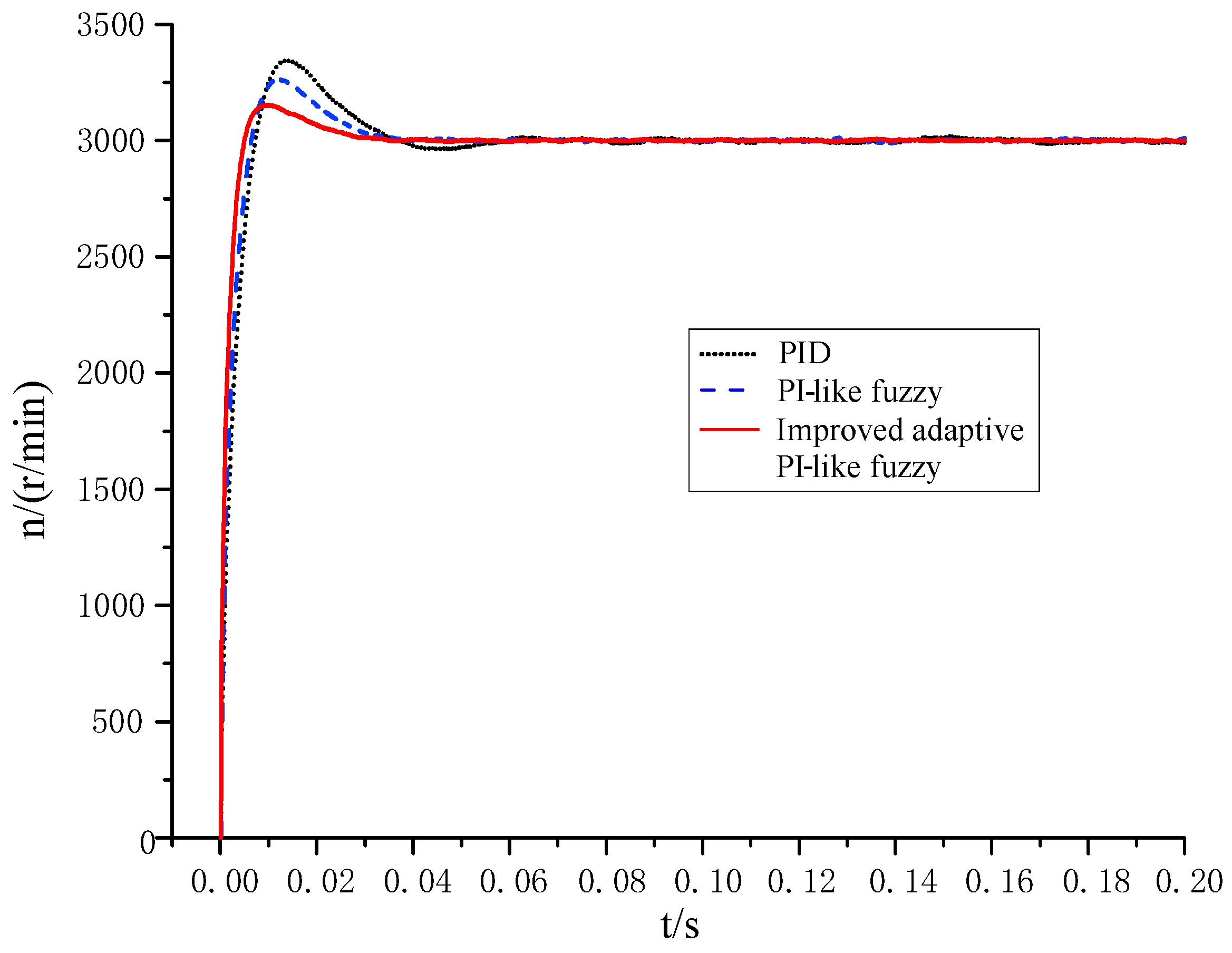
Before starting, the no-load starting speed of the motor is set to be rated at 3000 r/min. During the operation of the PMSM, the speed variable in the DSP program is transmitted to the host computer in real time, and the saved rotational speed data are visualized by Origin 2021 software, as shown in Figure 9. From the experimental waveforms of the PMSM speed in Figure 8, the following comparative analysis results are obtained:
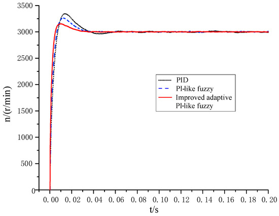
Figure 9.
Experimental response waveforms of PMSM speed using different controllers.
- (1)
- When using the traditional PI controller, the overshoot of the speed is the largest (about 11.4%), and the regulation time is the longest (about 0.049 s).
- (2)
- When using the traditional PI-like fuzzy controller, the overshoot of the speed is smaller (about 8.7%), and the regulation time is shorter (about 0.03 s).
- (3)
- Compared with the traditional PI controller and PI-like fuzzy controller, when the improved adaptive PI-like fuzzy controller is adopted, the PMSM system has the optimal dynamic performance, with the smallest overshoot (about 5.1%) and the shortest regulation time (about 0.025 s).
- (4)
- The experimental results of the starting process are basically consistent with the simulation results.
5. Conclusions
In this paper, to solve the problems of large overshoot and limited adaptive capability of the pure PI-like fuzzy control system, taking the surface-mounted PMSM as controlled object, an adaptive PI-like fuzzy control scheme based on the observation of normalized error acceleration was proposed. The proposed improved adaptive PI-like fuzzy control system was compared with a system based on a traditional PID controller and one based on the pure PI-like fuzzy controller, respectively. The research conclusions based on the simulation and experimental results are as follows:
- (1)
- Based on the real-time identification of the dynamic response state of the PMSM system, the proposed improved adaptive PI-like fuzzy control algorithm can adjust the output of the PI-like fuzzy controller online at different stages of the system response, thus effectively improving the adaptivity of the fuzzy control system of the PMSM.
- (2)
- Compared with the control algorithms of PID controller and pure PI-like fuzzy controller, when using the proposed improved adaptive PI-like fuzzy control algorithm, the PMSM system obtains good dynamic and static control performance, it obtains the relatively best dynamic performance index, and it has a larger adaptive adjustment range and stronger anti-interference ability. Whether during the no-load start-up or speed change process of the PMSM system, when the improved adaptive PI-like fuzzy control algorithm is used, it can enable the system to obtain smaller overshoot amount and shorter regulation time; when the load is applied suddenly, the motor speed has the smallest dynamic drop and can recover to the given speed in about 0.0035 s.
The structure and adaptive rules of the proposed improved adaptive PI-like fuzzy controller have a certain degree of general applicability, and can be generalized and applied to the speed regulation system of other AC motors. It is worth noting that, in order to improve the dynamic regulation accuracy of the adaptive mechanism, 49 fuzzy rules were adopted in this paper for the output adjustment of the PI-like fuzzy controller, as shown in Table 2. However, the adoption of more fuzzy rules means that the design process is more cumbersome, and some of the fuzzy rules in Table 2 may not be activated in the control process. Therefore, one of our future research directions is to further simplify the fuzzy rules without losing too much control accuracy, to make the design of the fuzzy controller simpler and more practical.
Author Contributions
Conceptualization, W.B.; Methodology, S.G.; Investigation, J.L.; Resources, J.L.; Data curation, Z.F.; Writing—original draft, S.G.; Writing—review & editing, Z.F.; Supervision, W.B. All authors have read and agreed to the published version of the manuscript.
Funding
The supports of the National Natural Science Foundation of China (51277053) and the Key scientific and technological project in Henan province (202102210095) are acknowledged.
Data Availability Statement
The original contributions presented in the study are included in the article, further inquiries can be directed to the corresponding authors.
Conflicts of Interest
The authors declare no conflicts of interest.
Abbreviations
| PMSM | Permanent magnet synchronous motor |
| FLC | Fuzzy logic controller |
| NEAO | Normalized Error Acceleration Observer |
| UOD | Universe of discourse |
References
- Gierczynski, M.; Jakubowski, R.; Kupiec, E.; Seredyński, M.; Jaworski, M.; Grzesiak, L. Modeling of the fourth-generation Toyota Prius traction machine as the reference for future designs. Energies 2024, 17, 4796. [Google Scholar] [CrossRef]
- Kang, E.L.; Cai, S.C. Design of self-constructing fuzzy neural network controller for permanent magnet synchronous motor. Electr. Mach. Control 2023, 27, 92–101. [Google Scholar]
- Zeng, X.L.; Wang, W.Q.; Wang, H.Y. Adaptive PI and RBFNN PID Current decoupling controller for permanent magnet synchronous motor drives: Hardware-validated results. Energies 2022, 15, 6353. [Google Scholar] [CrossRef]
- Zhen, S.C.; Li, Y.Y.; Liu, X.L.; Wang, J.; Chen, F.; Chen, X. A Lyapunov-based robust control for permanent magnet synchronous motor in the modular joint of collaborative robot. Robotic 2023, 41, 1389–1406. [Google Scholar] [CrossRef]
- Li, Q.F.; Liu, S.C.; Fang, W.D.; Li, X.; Tse, Z. Sideband vibration suppression of interior permanent magnet synchronous motors for electric vehicles under multiple operating conditions. IEEE Trans. Transp. Electrif. 2023, 9, 322–335. [Google Scholar] [CrossRef]
- Cong, Y.; Kang, E.L. Design of fuzzy sliding mode speed controller for permanent magnet synchronous motor. Electr. Mach. Control 2022, 26, 98–104. [Google Scholar]
- Zhou, L.; Su, M.X.; Wang, J. Fuzzy multi-vector model predictive control of permanent magnet synchronous motor. J. Electr. Eng. 2022, 17, 181–192. [Google Scholar]
- Zhang, L.; Ma, J.Q.; Wu, Q.M.; He, Z.Q.; Qin, T.; Chen, C. Research on PMSM speed performance based on fractional order adaptive fuzzy backstepping control. Energies 2023, 16, 6922. [Google Scholar] [CrossRef]
- Lv, X.; Chen, J.; Lv, C.X.; Dong, Y.H. Adaptive control of permanent magnet synchronous motor based on fuzzy logic. Control Eng. China 2022, 29, 837–843. [Google Scholar]
- Makhloufi, K.; Bousserhane, I.K.; Zegnoun, S.A. Adaptive fuzzy sliding mode controller design for PMLSM position control. Int. J. Power Electron. Drive Syst. 2021, 12, 674. [Google Scholar] [CrossRef]
- Novak, Z.; Novak, M. Adaptive PLL-based sensorless control for improved dynamics of high-speed PMSM. IEEE Trans. Power Electron. 2022, 37, 10154–10165. [Google Scholar] [CrossRef]
- Liu, X.; Deng, Y.; Li, H.; Cao, H.; Sun, Z.; Yang, T. Composite control based on FNTSMC and adaptive neural network for PMSM system. ISA Trans. 2024, 151, 198–211. [Google Scholar] [CrossRef] [PubMed]
- Wang, S.C.; Liu, Y.H. A modified PI-like fuzzy logic controller for switched reluctance motor drives. IEEE Trans. Ind. Electron. 2010, 58, 1812–1825. [Google Scholar] [CrossRef]
- Jiang, Y.; Chen, G.Z.; Jiang, J.W. Design of fuzzy adaptive control system for permanent magnet synchronous motor. Electron. Des. Eng. 2022, 30, 11–15+22. [Google Scholar]
- Damarla, I.; Venmathi, M.; Krishnakumar, V.; Anbarasan, P. Performance analysis of FEC based SR motor drive using fuzzy tuned PI controller. Circuit World 2024, 50, 293–307. [Google Scholar] [CrossRef]
- Mudi, R.K.; Pal, N.R. A robust self-tuning scheme for PI-and PD-type fuzzy controllers. IEEE Trans. Fuzzy Syst. 1999, 7, 2–16. [Google Scholar] [CrossRef]
- Centeno, E.; Mendoza, M.J.; Pinedo, C.F.; Kim, W.; Roche, E.; Vela, E.A. Incremental PI-like fuzzy logic control of a vacuum-powered artificial muscle for soft exoskeletons. In Proceedings of the IEEE International Conference on Advanced Robotics and Its Social Impacts (ARSO), Berlin, Germany, 5–7 June 2023; pp. 53–58. [Google Scholar] [CrossRef]
- Liu, X.; Zhou, Z.; Wu, Q.; Yang, Y.; Zhu, X. Research on Vector Control of PMSM Based on Fuzzy PI. In Lecture Notes in Electrical Engineering, Proceedings of the 15th Chinese Intelligent Systems Conference; Springer: Singapore, 2020; Volume 2, pp. 1–9. [Google Scholar]
- Mitra, P.; Dey, C.; Mudi, R.K. Fuzzy rule-based set point weighting for fuzzy PID controller. SN Appl. Sci. 2021, 3, 651. [Google Scholar] [CrossRef]
- Mastacan, L.; Dosoftei, C.C. Temperature fuzzy control system with Mamdani controller. In Proceedings of the International Conference and Exposition on Electrical and Power Engineering (EPE), Iasi, Romania, 18–19 October 2018; pp. 352–356. [Google Scholar]
- Mohamed, M.A.G.; Ghany, A.G.M.A.; Bensenouci, A.; Bensenouci, M.-A.; Syed-Ahmad, M.N. Fuzzy Fractional-Order PID Tuned via Relative Rate Observer for the Egyptian Load Frequency Regulation. In Proceedings of the Twentieth International Middle East Power Systems Conference (MEPCON), Cairo, Egypt, 18–20 December 2018; pp. 103–109. [Google Scholar]
- Nguyen, D.T.; Ho, J.R.; Tung, P.C.; Lin, C.K. A hybrid PSO–GWO fuzzy logic controller with a new fuzzy tuner. Int. J. Fuzzy Syst. 2022, 24, 1586–1604. [Google Scholar] [CrossRef]
- Kurucu, M.C.; Eksin, I.; Güzelkaya, M. Normalized acceleration based online tuning of variable-order fractional derivatives: A case study on quadcopter position control. Int. J. Syst. Sci. 2024, 55, 1–16. [Google Scholar] [CrossRef]
- Zhu, Y.H.; Xue, L.Y.; Wei, H. Design of fuzzy PID controller based on self-organizing adjustment factors. J. Syst. Simul. 2011, 23, 2732–2737. [Google Scholar]


Disclaimer/Publisher’s Note: The statements, opinions and data contained in all publications are solely those of the individual author(s) and contributor(s) and not of MDPI and/or the editor(s). MDPI and/or the editor(s) disclaim responsibility for any injury to people or property resulting from any ideas, methods, instructions or products referred to in the content. |
© 2025 by the authors. Licensee MDPI, Basel, Switzerland. This article is an open access article distributed under the terms and conditions of the Creative Commons Attribution (CC BY) license (https://creativecommons.org/licenses/by/4.0/).