Abstract
The ongoing energy transition and decarbonization efforts have prompted the development of Hybrid Renewable Energy Systems (HRES) capable of integrating multiple generation and storage technologies to enhance energy autonomy. Among the available options, hydrogen has emerged as a versatile energy carrier, yet most studies have focused either on stationary applications or on mobility, seldom addressing their integration withing a single framework. In particular, the potential of Metal Hydride (MH) tanks remains largely underexplored in the context of sector coupling, where the same storage unit can simultaneously sustain household demand and provide in-house refueling for light-duty fuel-cell vehicles. This study presents the design and analysis of a residential-scale HRES that combines photovoltaic generation, a PEM electrolyzer, a lithium-ion battery and MH storage intended for direct integration with a fuel-cell electric microcar. A fully dynamic numerical model was developed to evaluate system interactions and quantify the conditions under which low-pressure MH tanks can be effectively integrated into HRES, with particular attention to thermal management and seasonal variability. Two simulation campaigns were carried out to provide both component-level and system-level insights. The first focused on thermal management during hydrogen absorption in the MH tank, comparing passive and active cooling strategies. Forced convection reduced absorption time by 44% compared to natural convection, while avoiding the additional energy demand associated with thermostatic baths. The second campaign assessed seasonal operation: even under winter irradiance conditions, the system ensured continuous household supply and enabled full recharge of two MH tanks every six days, in line with the hydrogen requirements of the light vehicle daily commuting profile. Battery support further reduced grid reliance, achieving a Grid Dependency Factor as low as 28.8% and enhancing system autonomy during cold periods.
1. Introduction
In the current era of rapid technological evolution, the transformation of the energy sector is no longer driven only by environmental compliance. It has become a strategic imperative to sustain economic growth, ensure supply security and support the electrification of emerging sectors [1]. The increasing complexity and decentralization of energy consumption patterns demand flexible, intelligent and high-efficiency systems that go beyond the traditional centralized fossil-fuel-based infrastructure [2].
In this context, the integration of renewable energy sources with advanced energy storage and conversion technologies is enabling the development of next-generation energy architectures. Among them, Hybrid Renewable Energy Systems (HRESs) have emerged as a viable and flexible solution for both standalone and grid-connected applications. Recent analyses have demonstrated that such systems, when properly sized and controlled, can substantially increase renewable self-consumption, reduce grid imports by more than 25%, and lower operational costs by nearly 10% [3,4], especially when advanced forecasting methods are implemented to improve the accuracy of the load and weather predictions [5]. By integrating renewable energy sources with Energy Storage Systems (ESSs), these setups help mitigate the inherent variability of renewables. This integration ensures a more stable and continuous power supply that can adapt to dynamic energy demands [6,7,8]. In this context, academic and industrial interest in HRES has significantly increased, driven by its huge potential toward the decarbonization target, further enhanced by its integration with advanced control strategies [9].
While early HRES research and applications focused primarily on photovoltaic (PV), wind turbines and diesel generators or battery backup technologies, recent trends highlight the need to improve the sustainability, autonomy and flexibility of these systems, particularly in remote, off-grid, or isolated contexts [10]. Integrating other energy vectors, such as hydrogen, into HRES architecture has therefore become an increasingly compelling research frontier. In fact, the need for long-term, non-seasonal and high-density energy storage has pointed to hydrogen as a strategic solution [11,12].
Indeed, green hydrogen, i.e., produced via electrolysis using renewable electricity, offers a zero-emission alternative to conventional fuels and can serve as both a storage medium and an energy carrier [13]. Its integration into hybrid energy systems has shown potential in extending the availability of renewable electricity beyond production peaks.
Almost all HRES applications involving hydrogen storage rely on high-pressure gaseous tanks, typically operating within 350 to 700 bar [13,14,15]. Although technologically mature, this storage solution presents several limitations, including high infrastructure costs, stringent safety requirements and low volumetric energy density. In addition, high-pressure storage requires greater energy inputs for compression and more expensive compression hardware, as high-performance compressors are needed to reach such pressures, further increasing overall system costs. A promising alternative to high-pressure storage, still marginally explored, is the use of solid-state hydrogen storage systems based on Metal Hydrides (MHs). MH tanks operate at much lower pressures, reducing both compression energy demand and infrastructure costs. They also offer higher volumetric energy density compared to conventional compressed gas solutions [16], although their long-term cycling stability and degradation still require further study. However, Metal Hydrides are characterized by a specific thermodynamic behavior: the hydrogen absorption process is exothermic, while the desorption process is endothermic. If not properly managed, these temperature variations can critically affect system operation, leading to an interruption in hydrogen flow, which compromises the system’s reliability and continuity. Consequently, thermal management becomes a key functional aspect in the design and operation of MH-based storage systems, as emphasized by both Chung and Ho [17] and Nguyen and Shabani [18]. The former provided a detailed two-dimensional simulation of thermal–fluid interactions within a metal hydride canister, highlighting how inadequate heat removal or supply significantly slows reaction kinetics and leads to spatial temperature gradients. Furthermore, the latter demonstrated that improper thermal control in standalone solar–hydrogen systems may reduce storage performance by roughly 10–20% in energy terms and can increase refueling times by a factor of 3–4, underscoring the need for tailored solutions such as PCM-based thermal buffers to manage the significant heat loads generated or absorbed during hydrogen cycling.
Several studies have then started to explore this storage option. Drawer et al. evaluated Metal Hydrides hydrogen storage for both stationary and transportation applications [19]. Yunez-Cano et al. investigated a solar–hydrogen hybrid energy system integrated into a mobile sustainable house in Mexico [20]. In their configuration, hydrogen was produced via a Proton Exchange Membrane Water Electrolyzer (PEMWE), stored in two commercial Metal Hydrides tanks and later used by PEM Fuel Cells (PEMFCs) to supply electricity during periods of insufficient solar generation. Similarly, the work of Endo et al. [21] and Segawa et al. [22] demonstrated the practical viability of MH storage systems in urban, building-integrated applications, through the development of the Hydro Q-BiC system, a green hydrogen energy utilization prototype employing TiFe-based alloys for low-pressure, low-temperature hydrogen storage. Their systems were able to reliably operate under variable weather and load conditions and showcased advanced thermal management strategies, thus enabling efficient and reliable power and heat supply in commercial buildings. Finally, Kumar et al. [23] developed a comprehensive model of a hybrid microgrid and evaluated the impact of thermophysical properties on MH behavior. Their results highlighted how materials such as LaNi5 and Hydralloy C5, due to their favorable desorption characteristics at low temperatures and pressures, are particularly suitable for transient operation with PEMFCs.
Nevertheless, to the authors’ knowledge, the vast majority of research and real-world implementations continue to adopt hydrogen primarily as a long-term energy storage medium: excess renewable electricity is converted into hydrogen via electrolysis, stored and subsequently reconverted into electricity through Fuel Cells (FCs) during periods of low renewable generation [13,14,24]. This closed-loop cycle has been widely adopted in both off-grid and grid-connected contexts, with techno-economic analyses supporting its efficacy in enhancing energy autonomy and reducing carbon emissions [11,25]. However, while the stationary use of hydrogen in HRES is well documented, its direct utilization for powering lightweight vehicles in micromobility applications remains largely unexplored. In such contexts, where space and weight constraints limit the feasibility of large battery systems, hydrogen offers a promising alternative to extend vehicle autonomy without compromising design or usability. As highlighted by Offer et al. in [26] and by Jorgensen in [27], battery electric vehicles, although highly efficient, are inherently limited by the low gravimetric energy density of electrochemical storage. As energy demand increases, the mass and volume of battery packs grow disproportionately, which can severely impact the design and overall efficiency of compact vehicles. Hydrogen-powered systems, by contrast, allow for the separation of energy storage from power delivery, offering greater flexibility in packaging and vehicle layout. The high gravimetric energy density achievable with hydrogen enables extended range without excessive weight penalties. Integrating residential hydrogen production with decentralized, low-pressure refueling infrastructures could thus pave the way for a new class of sustainable micromobility solutions, expanding the role of HRES beyond stationary supply into the domain of urban transport.
In this regard, the present study introduces a broader perspective compared to existing MH-based HRES works, by jointly addressing stationary and mobility sectors within the same framework. To the authors’ knowledge, previous studies have typically analyzed either building-integrated or transportation applications in isolation. This work explicitly investigates sector coupling, demonstrating how residential hydrogen production and storage can simultaneously sustain household loads and enable in-house refueling for micromobility. This dual focus represents the fundamental novelty of the proposed approach and sets the basis for the research question addressed in this manuscript.
Current research seldom examines autonomously produced hydrogen for urban micromobility within a residential Hybrid Renewable Energy System (HRES). In particular, the technical feasibility of employing a low-pressure metal hydride (MH) tank in such configurations remains largely unexplored, especially when considering the complex interplay between thermophysical behavior, thermal management requirements and system-level integration. This work aims to address this gap by evaluating the potential of combining photovoltaic generation, PEM electrolysis and MH storage into a domestic HRES designed to power both household loads and a fuel-cell-based light-duty vehicle. The proposed closed-loop architecture seeks to minimize reliance on external compression and refueling infrastructure, leveraging the high volumetric density, operational safety and moderate working pressures (<30 bar) offered by solid-state hydrogen storage. By analyzing both the benefits and the inherent limitations of MH technology in dynamic operating conditions, this study contributes to the broader discussion on its practical applicability for future self-sufficient energy ecosystems.
To investigate this potential, a fully dynamic MATLAB/Simulink model was implemented. It resolves time-dependent interactions among photovoltaic power, domestic demand (including the recharging of a Battery Electric Vehicle (BEV) battery pack), electrolytic hydrogen production for refueling the FC hybrid vehicle tanks, lithium-ion battery buffering, and thermo-reactive absorption/desorption in MH storage units. The main contributions of this study can be summarized as follows:
- In-house refueling feasibility for urban mobility—Demonstration that photovoltaic-derived hydrogen stored in low-pressure MH cartridges enables regular recharge of light-duty fuel-cell vehicles without external hydrogen supply.
- Thermo-reactive one-dimensional MH modeling—Implementation of a transient 1-D model that couples mass diffusion, reaction kinetics and heat removal by forced convection, thereby capturing spatial temperature gradients overlooked by conventional lumped (0-D) representations and accurately predicting capacity and filling time constraints.
- Comprehensive system-level analysis—Evaluation of the proposed configuration through dynamic simulations that quantify seasonal HRES self-sufficiency, grid-import reduction and hydrogen-refill intervals.
Together, these elements substantiate the technical feasibility of an MH-based HRES that enhances residential energy autonomy while supporting the decarbonization of short-distance urban transport.
The remainder of this paper is structured as follows. Section 2 describes the methodology, including the governing equations, the implementation of the numerical model, and the initial conditions adopted for the simulations. Section 3 presents the results of two simulation campaigns, focusing, respectively, on the analysis of thermal management strategies for MH tanks and the seasonal performance of the proposed HRES. Finally, Section 4 discusses the main findings, highlighting both the benefits and the limitations of MH-based storage integration.
2. Materials and Methods
A hybrid renewable energy system represents a promising solution for achieving an effective balance between generation, storage and consumption of energy, while reducing dependency on the electrical grid. The proposed hybrid renewable energy system is designed to meet residential power demands by harnessing solar energy, with a battery storage unit ensuring continuity during periods of low or absent solar irradiance. A connection to the electrical grid is also included to allow energy withdrawal when the stored energy in the battery is insufficient (backup source) and to enable surplus energy export when production exceeds system demand. A PEM electrolyzer is included to produce green hydrogen, which is stored in metal hydride tanks intended for installation on a vehicle, where it will be used to supply the on-board fuel cell.
To assess the dynamic behavior and technical feasibility of such a system, a numerical model, shown in Figure 1, was developed using the Simulink platform. The simulation environment enables detailed analysis of the energy flows among the system’s main components (PV, PEM electrolyzer, storage battery) and eventually the grid.
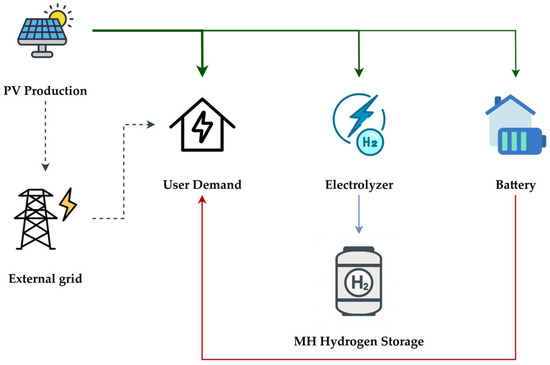
Figure 1.
System diagram for the proposed HRES. The thickness of the lines stands for the hierarchy of the distribution of the energy flow from the PV system, in green, to the various users. In red, the energy flow exiting from the storage battery. In blue, the hydrogen flow to the MH storage unit. The flows represented by dotted lines are those with lower priority (grid connection).
A simplified implementation, based solely on input and output power flows, has been adopted for the PV array, the storage battery and the grid connection. In contrast, the electrolyzer and the metal hydride tank have been described through a detailed mathematical model.
Meteorological data were sourced from a dedicated weather station installed on the rooftop of the Industrial Engineering Department at the Tor Vergata University of Rome (Italy), ensuring site-specific irradiance and temperature profiles for the simulations [28]. The dataset refers to the year 2020. The considered photovoltaic system consists of 42 SunPower E-Series panels, corresponding to an available installation area of 70 m2, representative of the rooftop surface of a typical countryside single-family residence. Each module provides a nominal power output of 327 W, resulting in a total installed capacity of approximately 13.8 kW for the PV array.
The clean energy produced by the PV array is primarily used to satisfy the domestic load, while any surplus is first supplied to the electrolyzer and then to the storage battery. Indeed, the integration of an energy storage system is essential to enhance the self-sufficiency of the hybrid system. Storage allows excess solar energy to be retained during peak production periods and utilized when generation is insufficient, such as during low irradiance conditions and night. This approach minimizes the reliance on the grid and optimizes renewable energy utilization. For this study, a Tesla Powerwall 2 battery was selected [29], with a nominal capacity of 13.5 kWh and an energy efficiency of approximately 90%. The system supports power flows up to 5 kW in both charging and discharging modes. The battery was modeled according to its nominal capacity and power limits, consistent with manufacturer specifications. Accordingly, a constant efficiency of 90% was imposed instead of adopting a more detailed equivalent circuit representation, as the primary objective of this study was to evaluate system-level energy flows rather than the electrochemical behavior of individual components. Future work may therefore incorporate more sophisticated battery models to further refine the predictive capability of the simulation. In addition, excess power is directed to the grid once the battery is fully charged.
Concerning the residential consumption modeling, the LoadProfileGenerator platform, developed by Pflugradt et al. [30], was employed. This tool enables the generation of detailed residential load profiles based on temporal consumption patterns. Specifically, the profile selected corresponds to a typical household composed of three occupants (two adults and one child) and includes the presence of a fuel-cell hybrid microcar, refueled through self-produced hydrogen and of a BEV charged via a 3.7 kW residential wallbox.
This configuration allows for a realistic representation of daily and seasonal variations in energy demand, ensuring accurate input data for the system-level simulation.
2.1. PEM Electrolyzer
The PEM electrolyzer was modeled, aiming to replicate the behavior of a 6 kW unit, consistent with the configuration proposed by Dale et al. in [31]. The electrolyzer consists of 20 cells in series, each with an active area of 86.4 cm2.
Following the approach proposed by García-Valverde et al. [32] and by Falcão and Pinto [33], the PEM electrolyzer model is developed under the following assumptions:
- Pressure effects are neglected due to low operating pressures.
- Temperature is assumed uniform across the electrolyzer. To this aim, a thermal management system was assumed to maintain the stack temperature within a narrow range around the target value, thus ensuring stable operating conditions.
- The electrolyzer is modeled as a series of identical electrolytic cells connected in series.
- The membrane is considered fully hydrated, making its conductivity a function of temperature only.
Under ideal (reversible) conditions, the potential difference between the anode and cathode, denoted as , represents the minimum electrical potential required to split a water molecule, excluding any thermal energy contributions. Under standard conditions, the Gibbs free energy change is , leading to:
where z is the number of electrons transferred per mole of hydrogen and F the Faraday’s constant.
Considering no external heat supply, the total energy required for the reaction, , must be provided entirely as electrical energy. Considering , the thermoneutral voltage becomes:
When current flows through the cell, the required voltage increases due to irreversible losses. These are typically categorized as activation, ohmic and mass transport losses. The actual cell voltage accounting for these losses is expressed as ([32]):
The reversible cell voltage, Erev, is determined from the empirical Nernst equation, valid for atmospheric pressure electrolysis ([32]):
The activation overpotential, , accounts for the anode and cathode contributions ([32]):
Here, and are the charge transfer coefficients, assumed equal and i is the current density.
The ohmic overpotential, , associated with internal stack resistance, , is expressed as:
The cell voltage, through the polarization curve, allows the determination of the current flowing via the electrolyzer, directly linked to hydrogen production via Faraday’s law:
where ncell is the number of cells and I the total current.
Considering real operating conditions, the actual hydrogen production rate accounts for the electrolyzer efficiency, , defined as the product of voltage efficiency, and Faraday efficiency, [34,35]:
where Eel is the actual operating voltage and iloss accounts for crossover and recombination losses at the cathode.
Consequently, the real molar hydrogen production rate is given by the following equation:
Due to the absence of detailed data concerning overvoltage contributions (Equations (7) and (8)), the stack potential was estimated by fitting the polarization curves provided in [31]; indeed, the stack potential can also be defined through the following semi-empirical equation, presented in [32]:
where R is the universal gas constant (), F is Faraday’s constant (), T is the operating temperature (303 K for the considered curves) and is the reversible cell voltage defined in Equation (4).
An Ordinary Least Squares (OLS) method was applied to these curves to determine the fitting coefficients of the latter, namely a(1), a(2) and a(3). The result is reported in Figure 2.
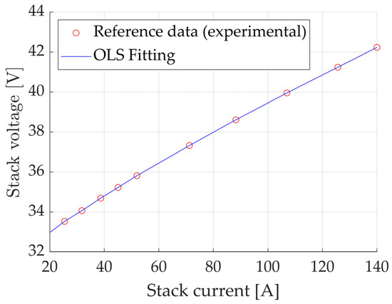
Figure 2.
Fitting of the polarization curve at T = 30 °C, performed using the OLS method. Reference data from [31].
The model input is the available electrical power, which, after accounting for the electrolyzer efficiency defined in Equation (10), determines the actual power delivered to the electrolysis reaction. From the polarization curve, stack current and voltage outputs are obtained and subsequently used to quantify the hydrogen production rate, according to Equation (10).
The electrolyzer operates at atmospheric pressure and it is connected to a compressor, which increases the hydrogen pressure up to 30 bar for the subsequent storage into the metal hydride tank. A control system was also implemented to manage electrolyzer operation, switching it off once the target storage pressure is reached and reactivating it when the pressure drops by 5 bar below the setpoint. This is due to the critical thermodynamic behavior of the storage system, discussed in the subsequent section.
Furthermore, the compressor’s energy consumption is considered in the Balance of Plant (BoP) and estimated assuming an isentropic efficiency of 70%.
2.2. Metal Hydrides Tank
Developing an accurate model for the hydrogen absorption and desorption dynamics in metal hydride (MH) tanks is essential to evaluate the technical viability of this hydrogen storage technology in sustainable applications. The performance of such systems is highly influenced by thermal stability, as hydrogen transfer processes are strongly dependent on both pressure and temperature. To this end, a one-dimensional model has been implemented in Simulink, incorporating the thermophysical properties of the alloy and the tank geometry.
The present work focuses on the MyH2 3000 tank by H2planet, filled with a Hydralloy C5 AB2-type alloy supplied by GfE [36,37], whose main physical and geometrical characteristics are summarized in Table 1.

Table 1.
H2planet MyH2 3000 technical specifications.
A one-dimensional Simulink model is presented to simulate the behavior of MH tanks, based on the thermophysical properties of the material and the system geometry. Hydrogen uptake is modeled as a function of temperature and equilibrium pressure of the hydride. While the present application focuses on the MyH2 3000 tank by H2planet, containing a Hydralloy C5 AB2-type alloy from GfE [36,37], a validation has been carried out to enhance model accuracy and reliability; in particular, experimental data reported by Jemni et al. for the LaNi5-based system [39] were used as a benchmark for the process.
The reaction mechanism is governed by the Van’t Hoff Equation (15), which relates the equilibrium pressure of the hydride to the temperature, provided that the reaction enthalpy and entropy are known.
However, this equation alone is not sufficient to fully describe the absorption and desorption processes, whose kinetics depend on the equilibrium pressure and temperature of the hydride, the partial pressure of the hydrogen gas, the actual density of the alloy and the reference density, as reported in Equation (16).
In particular, the temperature-dependent term () follows an Arrhenius-type formulation and requires knowledge of both the activation energy and pre-exponential factor, parameters that can be obtained from literature databases. The pressure-dependent term can take on different formulations, depending on the chosen kinetic model, as shown in [40]. In this work, logarithmic and linear forms are, respectively, adopted for the absorption and desorption reactions, as reported in Equations (17) and (18).
Finally, the process dynamics are described by the implementation of mass and energy conservation equations, which allow for the evaluation of the evolution of hydrogen and metal hydride densities, as well as temperature. In this model, following the study of Brown et al. [38], the gas-phase hydrogen temperature is assumed to be equal to that of the hydride at all spatial locations.
The PCI curves for the AB2 Hydralloy C5 alloy were derived from the experimental measurements reported by Capurso et al. [41] and then interpolated using the third-order rational function described by Hariyadi et al. in [40].
The data and the governing equations were integrated into a Simulink model with the aim of simulating the hydrogen absorption and desorption processes. Critical to the accuracy of the model is the evaluation of four key parameters (, , , ), which are required to characterize the reaction kinetics and dynamics. These values were obtained from the available literature data.
Regarding the thermophysical properties of hydrogen, a comparative analysis was performed by first treating the gas as real (using CoolProp) and then as ideal and the properties were found to be nearly identical within the operating range of the model. Consequently, hydrogen was modeled as an ideal gas.
Concerning the energy conservation equation, it was modified according to the reference node, thus to its position within the domains, in order to account for different heat exchange conditions, depending on the specific region considered. Additionally, convective heat exchange conditions are applied at the interface with the external environment, considering natural convection, forced convection and operation in a thermostatic bath.
The internal volume was divided into four domains, as illustrated in Figure 3. The lower section accounts for the metal hydride porosity and includes both the Metal Hydrides domain (MH) and the H2 domain (H2,inf). Above, the upper section consists solely of hydrogen gas (H2,sup). The fourth domain represents the steel tank.
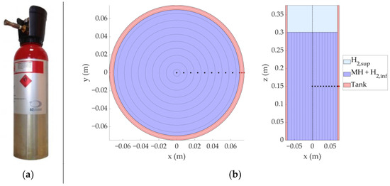
Figure 3.
(a) Real metal hydrides tank, model H2planet MyH2 3000; (b) System 1D discretization strategy. Black dots indicate the discretization nodes of the Metal Hydrides domain, while red dots represent the nodes of the tank domain.
Lower domains were discretized radially (1D approach): each node corresponds to a concentric cylindrical control volume with internal and external radii defined as and respectively. This configuration enables the calculation of heat fluxes between adjacent nodes by averaging thermophysical properties and accounts for the convective effects due to hydrogen mass flow within the domains. In the upper domain, given the assumed uniform thermophysical properties of the gas, a single node was used.
In the present formulation, only radial heat transfer was considered, while the axial component was neglected. This assumption is justified by the high aspect ratio (Height/Diameter) of the selected tank geometry, under which axial contributions become negligible compared to radial ones. For this reason, a one-dimensional radial discretization was adopted, which represents a good compromise between accuracy and computational efficiency.
An initial temperature equal to the external temperature was assumed for all the domains. Additionally, the hydride and the initial pressure of the hydrogen gas are assumed to be in equilibrium. These parameters allowed for the determination of the initial hydrogen concentration in the alloy, from which the initial density of the metal hydride was estimated. Lastly, the initial density of the free hydrogen gas was calculated using its thermophysical properties.
Model Validation
The metal hydride model was validated using the 2D CFD study by Chung and Ho [17], based on experimental tests performed by Jemni et al. [39] on a LaNi5 hydride alloy; physical and geometrical properties of the alloy were taken from the aforementioned references. The experimental setup, shown in Figure 4, includes a sealed vessel immersed in a thermostatic bath. Unlike the Simulink model, heat transfer also occurs at the tank base, which may cause minor deviations due to the significant base radius relative to the bed height. However, the initial and boundary conditions of the model, such as thermostatic bath temperature and initial pressure, were set to faithfully represent the benchmark. Physical and geometrical properties of the model are reported in Table 2.
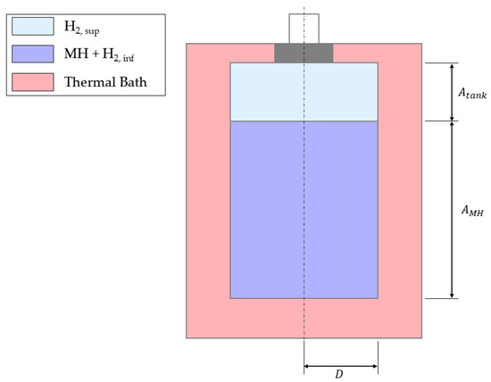
Figure 4.
Jemni et al. experimental apparatus [39]. Image adapted from [17].
Table 2.
LaNi5 experimental apparatus specifications [17].
The first validation comparison is related to the absorption process. The inlet pressure () was set to 8 bar, while the thermostatic bath temperature () was considered at both 293 K and 313 K. The initial system temperature was assumed equal to and the initial hydride density set to , with the initial pressure corresponding to the equilibrium absorption pressure at .
The temperature evolution was monitored at the node located at from the cylinder axis and compared with reference data from literature. The results of this comparison are shown in Figure 5. It is worth noting that the obtained profile (solid line) presents a good alignment with the benchmark ones, which is confirmed by the percentage deviation in red. A higher deviation is observed in the last stretch of the simulations (after 2500 s for the first case and after 4000 s for the second case): this is mainly due to the lack of heat transfer modeling in the vertical direction, which starts becoming significant in this low-sized sample when reaching the end of the absorption process.
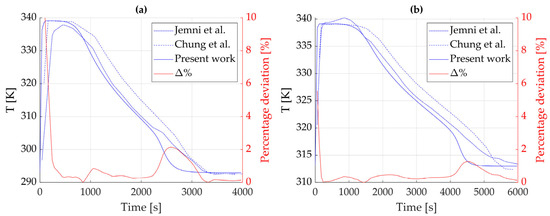
Figure 5.
Temperature evolution over time at r = 1.5 cm for (a) Text = 293 K and (b) Text = 313 K. In red, the percentage deviation between the present model and the results by Chung and Ho [17]. Data used for the absorption reaction is taken from tabulated values. Reference data from [17,39].
Further comparisons were made by fixing either pressure or temperature while varying the other, with the aim of assessing the hydrogen mass absorbed by the alloy. For the sake of clarity, data were again extracted at the node located at r = 1.5 cm.
In the first case (Figure 6a), the thermostatic bath temperature was set at , while the inlet hydrogen pressure, , varied between 8, 12 and 16 bar. In the second case (Figure 6b), was fixed at 8 bar and varied from 283 K to 313 K, with breakpoints each 10 K. As can be easily noted, the solid curves of both figures (which represent the simulated data) accurately follow the trends reported by the experimental data (described by the triangles in the figures) extracted from [17]. Therefore, the model is able to perform reliable predictions of the metal hydrides absorption process within a variable range of operating conditions.
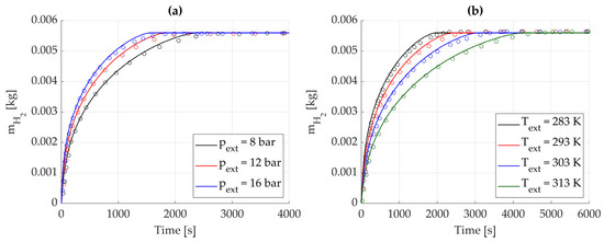
Figure 6.
Absorbed hydrogen mass over time. Reference data from [17] are represented by circles and solid lines represent numerical results from the proposed model. (a) Effect of inlet hydrogen pressure, with Text = 293 K. (b) Effect of the thermostatic bath temperature, with pext = 8 bar.
Concerning the desorption phase, the initial temperature of the hydride storage was set equal to the external fluid temperature, , with the initial pressure corresponding to the equilibrium pressure at this temperature. The process was divided into two stages: first, was linearly increased from the equilibrium pressure to the final target pressure, , over 100 s, then it was maintained constant at ; this was made to replicate the experimental tests performed by [17], whose results have then been used as a benchmark for validation.
As in the previous paragraph, simulations were performed by varying either or , while keeping the other parameter fixed, to evaluate the desorbed hydrogen mass. The initial stored mass, equal for all cases, is set as the maximum one, according with [17]. The results are presented in Figure 7.
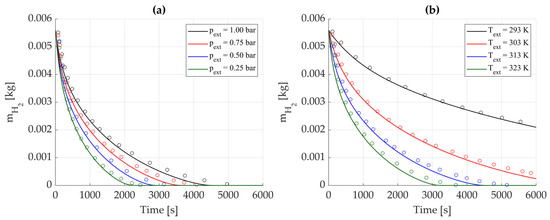
Figure 7.
Desorbed hydrogen mass over time. Reference data from [17] are represented by circles and solid lines represent numerical results from the proposed model. (a) Effect of external pressure, with Tₑₓₜ = 323 K. (b) Effect of thermostatic bath temperature, with pₑₓₜ = 0.25 bar.
The growing deviation over time, more evident than in the absorption case, is mainly due to axial heat transfer becoming relevant with time when the process is reaching the end; indeed, the presented model neglects axial energy conservation. Additionally, the low values of make the model highly sensitive, where even slight mismatches with literature data lead to substantial relative errors.
In conclusion, the obtained profiles prove the validation of the proposed MH model.
3. Results
This section presents the main findings of the simulations performed to evaluate the dynamic behavior and overall performance of the proposed hybrid renewable energy system. All simulations were conducted using real-world input data, including measured environmental conditions and radiative solar profiles, to ensure the results are representative of realistic operating scenarios.
The simulation time window was set to one full month, with two main case studies. This choice minimized the influence of initial conditions (e.g., storage battery SOC) and allowed observation of both steady-state and transient behavior. Additionally, the use of a month-long window allows for the analysis of both short-term dynamics and longer-term trends in system performance.
The first part of the analysis focuses on the summer period, investigating the effectiveness of different heat dissipation methods for the metal hydride tank during hydrogen absorption. Given the exothermic nature of the absorption process, comparisons were made between natural convection, thermostatic bath cooling and forced convection. This approach provides insights into the trade-offs between system complexity and thermal performance, with the objective of identifying a technically sound yet economically viable solution for managing the thermal loads associated with the hydride tank.
The second part of the analysis extends to a seasonal comparison, evaluating system performance across four representative months of the year. This seasonal assessment was designed to verify the operation of the integrated system throughout the entire year under varying environmental conditions. Key performance indicators include the total amount of hydrogen absorbed by the metal hydride tanks, the household energy balance and the system’s operational behavior in response to fluctuating solar irradiance. In this context, the estimation of vehicle hydrogen consumption, based on real driving data, was essential to determine the frequency of metal hydride tank replacements, which in turn defines the required operating schedule of the PEM electrolyzer.
Together, these analyses provide a comprehensive understanding of the system’s performance under both typical and critical operating conditions, supporting the evaluation of design choices and control strategies for future development.
3.1. Heat Dissipation Methods for the Metal Hydride Tank
The thermal management of the metal hydride tank plays a crucial role in the overall performance of the hydrogen absorption process. Due to the exothermic nature of the hydrogenation reaction, effective heat dissipation is required to maintain favorable operating temperatures and avoid premature saturation of the tank, which would otherwise lead to incomplete hydrogen absorption and reduced storage capacity.
To this end, a simulation campaign was conducted to compare three different cooling strategies: natural convection, thermostatic bath cooling and forced convection. The goal was to assess the impact of each method on the thermal behavior of the tank and, consequently, the total amount of hydrogen absorbed over the simulation period. In this context, a simulation stop criterion was defined to terminate the analysis once the absorbed hydrogen mass reached 99% of the maximum storable capacity, corresponding to approximately 270 g per tank, as indicated in Table 1.
Additionally, the hydrogen production of the electrolyzer is directly linked to the availability of solar power, so the operation of the device is inherently intermittent. During nighttime hours, or when solar generation is insufficient, the electrolyzer is turned off and hydrogen production is temporarily halted. This behavior, combined with the electrolyzer control strategy introduced in Section 2.1, allows the metal hydrides to relax thermally and kinetically, preventing critical situations in which the hydrogen flux might be interrupted due to excessive temperature or pressure build-up within the tank.
The comparative outcomes of the three cooling strategies are reported in Figure 8, which shows the hydrogen mass stored in the MH tank as a function of time during summer operation. For the sake of clarity, the MH tanks were assumed to operate in an indoor environment thermally isolated from external weather conditions, with the ambient temperature set to 20 °C. The selection of convective heat transfer coefficients for each scenario was made to reflect typical operating conditions, ranging from passive to highly active cooling approaches. Specifically, for the natural convection case, a convective heat transfer coefficient of was assumed, representing a scenario without forced airflow and relying solely on ambient heat exchange. In the thermostatic bath configuration, using water as the cooling medium, the coefficient was set to , accounting for the high heat transfer efficiency provided by liquid cooling systems operating under controlled temperature conditions. Finally, for the forced convection case, the convective heat transfer coefficient was estimated based on the correlations presented in [42], describing the heat transfer behavior of an air stream flowing transversely over a cylindrical surface. By considering an air velocity of , the resulting convective heat transfer coefficient was calculated to be approximately .
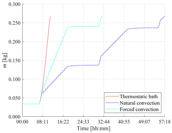
Figure 8.
Hydrogen mass absorbed by the metal hydride tank over time for different cooling strategies: thermostatic bath, natural convection and forced convection.
It is evident that the use of a thermostatic bath represents the most effective solution for achieving a rapid and complete filling of the metal hydride tank, allowing for full saturation in approximately 11 h. In contrast, the natural convection scenario results in a significantly slower absorption process, requiring around 57 h to complete. The forced convection configuration yields an intermediate performance, with the tank reaching full capacity in about 32 h. However, this solution offers the advantage of substantially lower operational costs compared to those associated with the thermostatic bath, making it a more economically attractive option for residential applications. Moreover, it is evident that the mass absorption profiles show characteristic behavior, with time windows in which the tank is recharged and others where a flat trend is observed. This is because the whole HRES is herein simulated and the intermittency of the recharge phase is associated with insufficient solar production and nighttime, where only the household load is met.
This behavior can be better understood by analyzing the temperature distribution within the tank, shown in Figure 9 for the thermostatic bath case, where each curve corresponds to a specific radial node. For the sake of clarity, the lowest profiles are associated with the external nodes, since better heat dissipation occurs through the edges, while the highest temperatures represent the internal nodes, whose heat dissipation is reduced due to the low conductivity. By considering the average temperature of the outermost node and the convective heat transfer coefficient adopted for this case, the resulting average thermal power dissipated by the tank is approximately 1.8 kW. However, maintaining such a thermal balance would require electrical power input for the refrigerant cycle of the thermostatic bath operation, thus increasing the overall energy demand for the process. In contrast, the forced convection configuration only requires the operation of a fan, which involves negligible power consumption, thereby reinforcing its suitability as a cost-effective solution for residential applications.
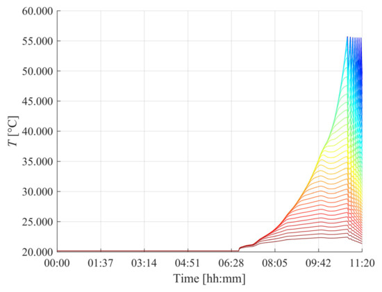
Figure 9.
Temperature distribution within the metal hydride tank over time for the thermostatic bath cooling scenario. Each curve represents the temperature evolution of a specific node in the system, from the core (blue) to the outer surface (red).
The findings from the presented case study highlight the necessity of aligning thermal management choices with the overall energy strategy of the HRES. Indeed, prioritizing solutions that minimize auxiliary consumption is crucial, particularly in a renewable-powered residential context, where energy availability is inherently variable. In this perspective, forced convection emerges as a potential compromise, maintaining acceptable thermal performance, therefore leading to a 2-day complete refilling operation, while limiting additional electrical demand. Building upon these results, the following section expands the analysis of the full operation of the HRES, considering the interplay between renewable energy generation, household consumption and hydrogen production over monthly seasonal cycles.
3.2. Hybrid Renewable Energy System Behavior
This section presents the results of the seasonal simulation campaign, aimed at evaluating the overall performance of the hybrid renewable energy system over an extended operating period. The analysis covers a full month of operation, providing insights into the dynamic behavior of the system under varying environmental conditions and solar resource availability.
The objective is to assess the capability of the HRES to ensure household energy self-sufficiency while simultaneously supporting hydrogen production for the refilling of the metal hydride storage tanks. Special attention is given to the interaction between renewable energy generation, household consumption and electrolyzer operation, considering the inherent intermittency of solar power and its impact on the production of hydrogen.
In this context, the estimation of vehicle hydrogen consumption is used as a reference to determine the required frequency of metal hydride tank replacements. A daily commuting distance of 30 km (according to the mean distance of urban trips in Italy and Europe [43,44]) has been assumed for the fuel-cell hybrid microcar equipped with a 2 kW fuel cell system, two metal hydride tanks and a 5.1 kWh battery [45] and vehicle simulations have indicated an effective driving range of approximately 200 km. Consequently, a swap of the two tanks is scheduled every 6 days, ensuring continuous vehicle operation while maintaining alignment with the hydrogen production capacity of the residential HRES. The referenced case study can be generalized to configurations with similar characteristics in terms of powertrain size and driving range, typical of light-weight vehicles. In such cases, the adopted replacement interval for the metal hydride tanks remains a valid reference, as it reflects typical usage patterns in urban mobility scenarios. This allows the proposed hydrogen production strategy to be applied more broadly within residential HRES-based mobility frameworks.
The seasonal dynamics of the entire HRES are summarized in Figure 10. Panel (a) reports the system power flows for the four representative months (namely April, July, October and January), while panel (b) shows the corresponding battery state of charge. These periods were selected to capture the seasonal variability in solar irradiance and its influence on the overall energy balance of the hybrid renewable energy system.
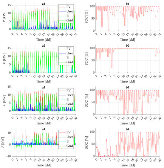
Figure 10.
(a) Power flow distribution across the system components; (b) state of charge (SOC) of the integrated storage battery. The labels (1) to (4) correspond to different periods of the year: (1) spring, (2) summer, (3) autumn and (4) winter. For the “Grid” power flow, positive values indicate power injected into the grid, while negative values indicate power drawn from the grid.
As expected, the winter scenario exhibits the lowest solar energy availability, which leads to a more frequent need to draw electricity from the grid to meet residential demand.
Residential load profiles show distinct peaks during evening hours, typically coinciding with the activation of the wallbox used for vehicle charging. In this context, the battery storage system (which state of charge is shown in Figure 10b) plays a crucial role as a buffer, storing excess solar energy generated during the day and releasing it during periods of low or no generation, thereby reducing reliance on the electrical grid and improving system autonomy.
The electric power delivered to the electrolyzer also varies significantly with the availability of solar energy and the competing demand from the household. Nonetheless, across all scenarios, the system consistently manages to refill two metal hydride tanks within the predefined six-day interval between tank swaps. Each tank can store approximately 270 g of hydrogen in solid form, thus ensuring continuity of supply for the microcar’s onboard fuel-cell system.
These results also confirm the adequacy of a forced convention-based cooling system for hydride tanks. In combination with the electrolyzer control strategy introduced in Section 2.1, this solution proves effective in maintaining the thermodynamic conditions required for stable hydrogen absorption.
To provide a more quantitative assessment of the system’s energy performance, a set of key performance indicators (KPIs) was evaluated over a full solar year. These indicators were computed by extrapolating the results obtained from the monthly simulations to represent the behavior of the system throughout the year. Figure 11 summarizes the corresponding energy flows, offering a visual overview of the balance between photovoltaic generation, household demand, storage dynamics and grid exchanges. The Self-Sufficiency Ratio (SSR), defined as the fraction of total energy demand covered by photovoltaic production, was calculated to be 3.53, indicating that the system can generate significantly more energy than required on an annual basis. Conversely, the Self-Consumption Ratio (SCR), which reflects the share of generated solar energy that is directly utilized within the household, was found to be 0.28, suggesting that a considerable portion of renewable energy is either stored or injected into the grid. The Net Grid Energy Balance (NGEB), accounting for the total energy exchanged with the grid, amounts to approximately positive 64 MWh, while the Grid Dependency Factor (GDF), defined as the share of energy demand covered by grid imports, was estimated at 28.8%. These values, reported in Table 3, reflect the seasonal variability of solar availability and confirm the crucial role of the integrated battery storage system in reducing dependence on the electrical grid.
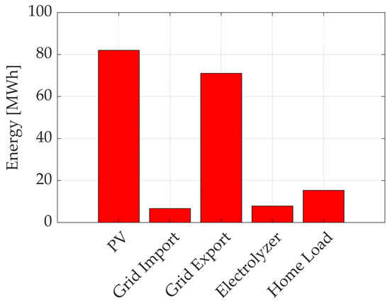
Figure 11.
Annual energy balance of the hybrid renewable energy system (HRES). Data are obtained by projecting monthly simulation results to the full year.
Table 3.
Key Performance Indicators for the proposed HRES.
Moreover, the SSR and SCR indicators highlight the significant room for optimization of the HRES considered, especially from the sizing standpoint; for instance, a downsized PV plant and a re-sized battery could significantly decrease the capital investment, thus reducing the grid-injected energy while keeping the self-sufficiency reasonable.
Beyond technical feasibility, it is worth noting that techno-economic evaluations reported in the literature ([46]) suggest that MH storage can be competitive with conventional compressed hydrogen when the overall infrastructure is considered. In particular, the simplified refueling requirements of MH tanks, which typically operate at pressures below 30–40 bar, lead to lower compression energy demand and significantly reduce the capital cost of compressors and dispensing equipment, two of the main cost drivers of high-pressure storage. Although material-related CAPEX for MH systems remains comparatively higher, the reduction in balance of plant and refueling infrastructure costs positions MH storage as a potentially viable alternative in residential and distributed energy contexts. Moreover, beyond cost considerations, the ability to operate at lower pressures and smaller scales is an enabling feature: unlike high-pressure storage, MH technology makes residential-scale hydrogen systems, such as the one proposed in this study, technically feasible.
For what concerns the scalability of the approach, the proposed model is inherently scalable, as it has been conceived to evaluate system-level energy flows rather than being limited to a specific system size. With reference to the transportation sector, this work emphasizes the role of micromobility, which has emerged as a key enabler of sustainable urban mobility. As extensively highlighted in the literature [47,48], micromobility reduces passenger car utilization for short journeys, alleviates congestion, and improves access to public transport through first- and last-mile connections. While a direct extension to larger vehicles is less immediate due to higher storage and performance requirements, micromobility provides a practical and effective application domain for the proposed framework. Future research will focus both on scaling up the model to Renewable Energy Communities (RECs) and on investigating the technical adaptations required for its application to larger vehicles.
4. Conclusions
Recent advances in renewable energy technologies, energy storage solutions and control systems have enabled the design of increasingly autonomous and efficient energy building solutions on the residential scale. In this context, Hybrid Renewable Energy Systems emerge as a flexible and technologically viable solution to support energy autonomy. Their potential is further enhanced when coupled with hydrogen technologies that enable seasonal storage and sector coupling. Such systems can achieve high levels of energy self-sufficiency while enabling innovative applications across both stationary and mobility sectors.
This study has explored a residential HRES powered by photovoltaic generation, capable of satisfying household energy demand, powering a PEM electrolyzer for green hydrogen production and recharging an electrical storage unit. The hydrogen produced is stored in solid form within metal hydride tanks, which can be deployed onboard light vehicles.
To investigate the dynamic behavior of the system and assess its performance under realistic operating conditions, a numerical model has been developed. This model incorporates the main physical and operational characteristics of the subsystems involved, including the PV array, the PEM electrolyzer, the storage battery and a validated model representing the thermofluid-dynamic behavior of metal hydride tanks. In particular, the MH model has been validated against literature data and has enabled detailed time-dependent analysis of energy flows, thermal interactions and storage dynamics across different seasonal scenarios.
A first phase of analysis focused on the thermal management strategies applicable to the metal hydride tanks during the hydrogen absorption phase, evaluating increasingly effective, but progressively more energy-intensive, solutions. Initially, natural convection was considered as the baseline, followed by forced convection via direct airflow and finally by immersion in a thermostatic bath. While the latter enabled an 80% reduction in absorption time compared to natural convection, its application presents significant drawbacks related to high energy consumption for temperature maintenance and increased system complexity. Conversely, the forced convection system, implemented through fans delivering a controlled air stream to the hydride surfaces, achieved recharge times approximately 44% lower than the baseline, with negligible electrical consumption. These results led to the identification of forced convection as a suitable and balanced solution for the application under study, providing effective thermal control without compromising overall system efficiency.
A dedicated seasonal simulation campaign was then carried out to evaluate the long-term performance of the HRES under variable solar irradiance and load conditions. Four representative months (April, July, October and January) were selected to capture the influence of seasonality on photovoltaic generation and system autonomy. The results confirmed the capability of the system to ensure household energy self-sufficiency for most of the time (SSR = 3.53), while sustaining hydrogen production for mobility purposes. Despite the reduced solar input during winter, the system consistently managed to refill two metal hydride tanks every six days, the interval required to support daily commuting (20 km/day) of a common microcar powered by a fuel-cell system.
Overall, the results confirm the viability of low-pressure MH tanks in domestic HRES. A well-integrated thermal strategy is the key enabler for practical deployment. Unlike traditional storage, this approach provides a compact, safe, and infrastructure-independent pathway for hydrogen use, bridging the gap between energy production, storage, and sustainable transport. Building on these findings, the study also emphasized the need for continued optimization of energy dispatch and component sizing strategies to further enhance system autonomy and round-the-year performance.
To summarize, the main contributions of this study can be outlined as follows:
- Development of a fully dynamic numerical model of a residential HRES integrating PV, battery storage, PEM electrolysis and MH tanks, enabling a digital representation of energy flows and system interactions.
- Validation of a one-dimensional MH model, demonstrating the critical role of thermal management and identifying forced convection as the most suitable strategy for being a trade-off between energy intensity and thermal behavior.
- Seasonal simulations confirming household self-sufficiency (SSR = 3.53) and capability to sustain hydrogen production for micromobility, with two MH tanks refilled every six days even under winter conditions.
- Demonstration of the technical viability of low-pressure MH tanks as a compact, safe and infrastructure-independent alternative to high-pressure storage for combined stationary and mobility applications.
- Identification of future research directions, including component sizing optimization, predictive control strategies, and the assessment of MH cycling stability and degradation. Moreover, experimental validation will be conducted to strengthen the reliability of the models.
- Generalization of the framework to Renewable Energy Communities (RECs), to enhance the approach from a household level to a wider energetic community.
Author Contributions
Conceptualization, L.B., S.C. and V.M.; methodology, L.B., E.C. and A.P.; software, A.P.; validation, A.P.; formal analysis, E.C. and A.P.; investigation, A.P.; data curation, A.P.; writing—original draft preparation, L.B., E.C. and A.P.; writing—review and editing, L.B., E.C., S.C. and A.P.; supervision, L.B., S.C. and V.M.; project administration, L.B., S.C. and V.M. All authors have read and agreed to the published version of the manuscript.
Funding
This research received no external funding.
Data Availability Statement
Dataset available on request from the authors.
Conflicts of Interest
The authors declare no conflict of interest.
Abbreviations
The following abbreviations are used in this manuscript:
| ESS | Energy Storage System |
| FC | Fuel Cell |
| HRES | Hybrid Renewable Energy System |
| MH | Metal Hydride |
| PCM | Phase-Change Material |
| PEM | Proton Exchange Membrane |
| PV | Photovoltaic |
| WE | Water Electrolyzer |
References
- Schaeffer, G.J. Energy Sector in Transformation, Trends and Prospects. Procedia Comput. Sci. 2015, 52, 866–875. [Google Scholar] [CrossRef]
- Sioshansi, F.P.; Zamani, R.; Moghaddam, M.P. Energy transformation and decentralization in future power systems. In Decentralized Frameworks for Future Power Systems; Elsevier: Amsterdam, The Netherlands, 2022; pp. 1–18. [Google Scholar] [CrossRef]
- Gómez, J.C.L.; Aldaco, S.E.D.L.; Alquicira, J.A. A Review of Hybrid Renewable Energy Systems: Architectures, Battery Systems, and Optimization Techniques. Eng 2023, 4, 1446–1467. [Google Scholar] [CrossRef]
- Bartolucci, L.; Cordiner, S.; Mulone, V.; Rocco, V.; Rossi, J.L. Hybrid renewable energy systems for renewable integration in microgrids: Influence of sizing on performance. Energy 2018, 152, 744–758. [Google Scholar] [CrossRef]
- Bartolucci, L.; Cordiner, S.; Mulone, V.; Santarelli, M. Hybrid renewable energy systems: Influence of short-term forecasting on model predictive control performance. Energy 2019, 172, 997–1004. [Google Scholar] [CrossRef]
- Shezan, S.; Al-Mamoon, A.; Ping, H. Performance investigation of an advanced hybrid renewable energy system in Indonesia. Environ. Prog. Sustain. Energy 2017, 37, 1424–1432. [Google Scholar] [CrossRef]
- McIlwaine, N.; Foley, A.M.; Morrow, D.J.; Al Kez, D.; Zhang, C.; Lu, X.; Best, R.J. A state-of-the-art techno-economic review of distributed and embedded energy storage for energy systems. Energy 2021, 229, 120461. [Google Scholar] [CrossRef]
- Lipu, M.H.; Rahman, M.A.; Islam, Z.U.; Rahman, T.; Rahman, S.; Meraj, S.T.; Hossain, Y.; Mansor, M. Review of energy storage integration in off-grid and grid-connected hybrid renewable energy systems: Structures, optimizations, challenges and opportunities. J. Energy Storage 2025, 122, 116629. [Google Scholar] [CrossRef]
- Lian, J.; Zhang, Y.; Ma, C.; Yang, Y.; Chaima, E. A review on recent sizing methodologies of hybrid renewable energy systems. Energy Convers. Manag. 2019, 199, 112027. [Google Scholar] [CrossRef]
- Uc, D.A.P.; Aldaco, S.E.d.L.; Alquicira, J.A. Trends in Hybrid Renewable Energy System (HRES) Applications: A Review. Energies 2024, 17, 2578. [Google Scholar] [CrossRef]
- Mojumder, F.H.; Islam, T.; Rafi, M.R.; Asef, I.H.; Hasan, M.; Chowdhury, N.-U. Enhanced hybrid energy generation solutions for sustainable rural electrifications in Bangladesh: A system optimization and performance evaluation approach using HOMER Pro and MATLAB/Simulink. J. Energy Storage 2025, 115, 115971. [Google Scholar] [CrossRef]
- Elmasides, C.; Kosmadakis, I.E.; Athanasiou, C. A comprehensive power management strategy for the effective sizing of a PV hybrid renewable energy system with battery and H2 storage. J. Energy Storage 2024, 106, 114790. [Google Scholar] [CrossRef]
- Gómez, J.; Castro, R. Green Hydrogen Energy Systems: A Review on Their Contribution to a Renewable Energy System. Energies 2024, 17, 3110. [Google Scholar] [CrossRef]
- Maestre, V.; Ortiz, A.; Ortiz, I. Sustainable and self-sufficient social home through a combined PV-hydrogen pilot. Appl. Energy 2024, 363, 123061. [Google Scholar] [CrossRef]
- Battaglia, V.; Rehman, A.U.; Vanoli, L. Optimizing storage capacity in 100% renewable electricity supply: A GIS-based approach for Italy. Smart Energy 2025, 18, 100177. [Google Scholar] [CrossRef]
- Khan, H.B.; Zhang, T. Metal hydride hydrogen storage risk assessment: A review. J. Energy Storage 2025, 129, 117273. [Google Scholar] [CrossRef]
- Chung, C.; Ho, C.-J. Thermal–fluid behavior of the hydriding and dehydriding processes in a metal hydride hydrogen storage canister. Int. J. Hydrogen Energy 2009, 34, 4351–4364. [Google Scholar] [CrossRef]
- Nguyen, H.Q.; Shabani, B. Metal hydride thermal management using phase change material in the context of a standalone solar-hydrogen system. Energy Convers. Manag. 2020, 224, 113352. [Google Scholar] [CrossRef]
- Drawer, C.; Lange, J.; Kaltschmitt, M. Metal hydrides for hydrogen storage—Identification and evaluation of stationary and transportation applications. J. Energy Storage 2023, 77, 109988. [Google Scholar] [CrossRef]
- Yunez-Cano, A.; González-Huerta, R.d.G.; Tufiño-Velázquez, M.; Barbosa, R.; Escobar, B. Solar-hydrogen hybrid system integrated to a sustainable house in Mexico. Int. J. Hydrogen Energy 2016, 41, 19539–19545. [Google Scholar] [CrossRef]
- Endo, N.; Goshome, K.; Tetsuhiko, M.; Segawa, Y.; Shimoda, E.; Nozu, T. Thermal management and power saving operations for improved energy efficiency within a renewable hydrogen energy system utilizing metal hydride hydrogen storage. Int. J. Hydrogen Energy 2021, 46, 262–271. [Google Scholar] [CrossRef]
- Segawa, Y.; Endo, N.; Shimoda, E.; Yamane, T.; Maeda, T. Pilot-scale hydrogen energy utilization system demonstration: A case study of a commercial building with supply and utilization of off-site green hydrogen. Int. J. Hydrogen Energy 2023, 50, 26–36. [Google Scholar] [CrossRef]
- Kumar, K.; Alam, M.; Verma, S.; Dutta, V. Analysis of metal hydride storage on the basis of thermophysical properties and its application in microgrid. Energy Convers. Manag. 2020, 222, 113217. [Google Scholar] [CrossRef]
- Gulraiz, A.; Al Bastaki, A.J.; Magamal, K.; Subhi, M.; Hammad, A.; Allanjawi, A.; Zaidi, S.H.; Khalid, H.M.; Ismail, A.; Hussain, G.A.; et al. Energy advancements and integration strategies in hydrogen and battery storage for renewable energy systems. iScience 2025, 28, 111945. [Google Scholar] [CrossRef] [PubMed]
- Al-Ammar, E.A.; Habib, H.U.R.; Kotb, K.M.; Wang, S.; Ko, W.; Elmorshedy, M.F.; Waqar, A. Residential Community Load Management Based on Optimal Design of Standalone HRES With Model Predictive Control. IEEE Access 2020, 8, 12542–12572. [Google Scholar] [CrossRef]
- Offer, G.J.; Howey, D.; Contestabile, M.; Clague, R.; Brandon, N.P. Comparative analysis of battery electric, hydrogen fuel cell and hybrid vehicles in a future sustainable road transport system. Energy Policy 2010, 38, 24–29. [Google Scholar] [CrossRef]
- Jorgensen, K. Technologies for electric, hybrid and hydrogen vehicles: Electricity from renewable energy sources in transport. Util. Policy 2008, 16, 72–79. [Google Scholar] [CrossRef]
- Bartolucci, L.; Cordiner, S.; Mulone, V.; Rossi, J.L. Hybrid renewable energy systems for household ancillary services. Int. J. Electr. Power Energy Syst. 2019, 107, 282–297. [Google Scholar] [CrossRef]
- Tesla. Tesla Powerwall 2 Datasheet. Available online: https://energylibrary.tesla.com/docs/Public/EnergyStorage/Powerwall/2/Datasheet/en-us/Powerwall-2-Datasheet.pdf (accessed on 26 February 2025).
- Pflugradt, N.; Stenzel, P.; Kotzur, L.; Stolten, D. LoadProfileGenerator: An Agent-Based Behavior Simulation for Generating Residential Load Profiles. J. Open Source Softw. 2022, 7, 3574. [Google Scholar] [CrossRef]
- Dale, N.; Mann, M.D.; Salehfar, H. Semiempirical model based on thermodynamic principles for determining 6 kW proton exchange membrane electrolyzer stack characteristics. J. Power Sources 2008, 185, 1348–1353. [Google Scholar] [CrossRef]
- García-Valverde, R.; Espinosa, N.; Urbina, A. Simple PEM water electrolyser model and experimental validation. Int. J. Hydrogen Energy 2012, 37, 1927–1938. [Google Scholar] [CrossRef]
- Falcão, D.; Pinto, A. A review on PEM electrolyzer modelling: Guidelines for beginners. J. Clean. Prod. 2020, 261, 121184. [Google Scholar] [CrossRef]
- Yodwong, B.; Guilbert, D.; Kaewmanee, W.; Phattanasak, M. Energy Efficiency Based Control Strategy of a Three-Level Interleaved DC-DC Buck Converter Supplying a Proton Exchange Membrane Electrolyzer. Electronics 2019, 8, 933. [Google Scholar] [CrossRef]
- Koponen, J.; Ruuskanen, V.; Hehemann, M.; Rauls, E.; Kosonen, A.; Ahola, J.; Stolten, D. Effect of power quality on the design of proton exchange membrane water electrolysis systems. Appl. Energy 2020, 279, 115791. [Google Scholar] [CrossRef]
- AMG Titanium—GfE Metalle und Materialien GmbH. Hydralloy® C Datasheet. Available online: https://www.gfe.com/02_produkte_loesungen/01_legierungen/PDB/HYDRALLOY-C_2019-929_-2005-169_2004-732-_V8.pdf (accessed on 19 February 2025).
- h2planet. MyH2 3000—Cilindro per lo stoccaggio H2 in idruri metallici. Available online: https://www.h2planet.eu/it/detail/MyH23000 (accessed on 19 February 2025).
- Brown, T.; Brouwer, J.; Samuelsen, G.; Holcomb, F.; King, J. Accurate simplified dynamic model of a metal hydride tank. Int. J. Hydrogen Energy 2008, 33, 5596–5605. [Google Scholar] [CrossRef]
- Jemni, A.; Nasrallah, S.B.; Lamloumi, J. Experimental and theoretical study of a metal-hydrogen reactor. Int. J. Hydrog. Energy 1999, 24, 631–644. [Google Scholar] [CrossRef]
- Hariyadi, A.; Suwarno, S.; Denys, R.V.; von Colbe, J.B.; Sætre, T.O.; Yartys, V. Modeling of the hydrogen sorption kinetics in an AB2 laves type metal hydride alloy. J. Alloys Compd. 2022, 893, 162135. [Google Scholar] [CrossRef]
- Capurso, G.; Schiavo, B.; Jepsen, J.; Lozano, G.; Metz, O.; Saccone, A.; De Negri, S.; von Colbe, J.M.B.; Klassen, T.; Dornheim, M. Development of a modular room-temperature hydride storage system for vehicular applications. Appl. Phys. A 2016, 122, 236. [Google Scholar] [CrossRef]
- Engineers Edge. Nusselt Number for Forced Convection. Available online: https://www.engineersedge.com/heat_transfer/nusselt_number_13856.htm (accessed on 3 March 2025).
- ISFORT. 21° Rapporto Sulla Mobilità Degli Italiani; Consiglio Nazionale Economia e Lavoro: Roma, Italy, 2024. [Google Scholar]
- Eurostat. Passenger Mobility Statistics. 2021. Available online: https://ec.europa.eu/eurostat/statistics-explained/index.php?title=Passenger_mobility_statistics (accessed on 28 May 2025).
- Bartolucci, L.; Cennamo, E.; Cordiner, S.; Donnini, M.; Grattarola, F.; Mulone, V. Fuel Cell Hybrid Electric Vehicle: Validated Fuel Cell and Battery Pack Model to Enhance Reliability in Performance Predictions. In Proceedings of the WCX SAE World Congress Experience, Detroit, MI, USA, 16–18 April 2024. [Google Scholar]
- Danebergs, J.; Deledda, S. Can hydrogen storage in metal hydrides be economically competitive with compressed and liquid hydrogen storage? A techno-economical perspective for the maritime sector. Int. J. Hydrogen Energy 2023, 50, 1040–1054. [Google Scholar] [CrossRef]
- Ewert, A.; Brost, M.; Eisenmann, C.; Stieler, S. Small and Light Electric Vehicles: An Analysis of Feasible Transport Impacts and Opportunities for Improved Urban Land Use. Sustainability 2020, 12, 8098. [Google Scholar] [CrossRef]
- Abduljabbar, R.L.; Liyanage, S.; Dia, H. The role of micro-mobility in shaping sustainable cities: A systematic literature review. Transp. Res. Part D Transp. Environ. 2021, 92, 102734. [Google Scholar] [CrossRef]
Disclaimer/Publisher’s Note: The statements, opinions and data contained in all publications are solely those of the individual author(s) and contributor(s) and not of MDPI and/or the editor(s). MDPI and/or the editor(s) disclaim responsibility for any injury to people or property resulting from any ideas, methods, instructions or products referred to in the content. |
© 2025 by the authors. Licensee MDPI, Basel, Switzerland. This article is an open access article distributed under the terms and conditions of the Creative Commons Attribution (CC BY) license (https://creativecommons.org/licenses/by/4.0/).