Article

Study of Superconducting Fault Current Limiter Functionality in the Presence of Long-Duration Short Circuits

1
Institute of Automatic Control, Electronics and Electrical Engineering, University of Zielona Gora, ul. Prof. Z. Szafrana 2, 65-417 Zielona Gora, Poland
2
Faculty of Electrical Engineering, Wroclaw University of Science and Technology, Wyb. Wyspianskiego 27, 50-370 Wroclaw, Poland
3
Ekoenergetyka—Polska S.A., ul. Nowy Kisielin—Rozwojowa 7A, 66-002 Zielona Gora, Poland
*
Author to whom correspondence should be addressed.
Energies 2025, 18(19), 5302; https://doi.org/10.3390/en18195302
Submission received: 30 July 2025 / Revised: 3 October 2025 / Accepted: 6 October 2025 / Published: 8 October 2025
(This article belongs to the Section F: Electrical Engineering)

Abstract

In this paper, superconducting fault current limiter (SFCL) operation in the presence of a long-duration fault is presented. The SFCL device utilizes second-generation high-temperature superconducting (2G HTS) tapes, which exhibit zero resistance under normal operating conditions. When the current exceeds the critical threshold specific to the superconducting tape, then it undergoes a transition to a resistive state—a phenomenon known as quenching. As a consequence, this leads to introducing impedance into the circuit, effectively limiting the magnitude of the fault current. Additionally, this transition dissipates electrical energy as heat within the material. The generated energy corresponds to the product of the voltage drop across the quenched region and the current flowing through it during the fault duration. In specific configurations of the power system, it is expected that the SFCL should limit the fault current for an extended period of time. In such a situation, a certain amount of energy will be generated, and it must be verified that the tape loses its properties or parameters (e.g., lowering the critical current value) or is destroyed. Therefore, experimental tests of the tapes were conducted for various short-circuit current, voltage drop, and short-circuit duration values to assess the effect of the amount of generated energy on the 2G HTS tape. Additionally, recommendations are presented on how to protect the SFCL during long-lasting short circuits.

1. Introduction

High-temperature superconducting tape is a modern material that can be used in electrical power systems [1,2]. This material exhibits zero resistance when operating in the superconducting state. This enables near-lossless current conduction and significantly reduced energy losses compared to conventional conductors. Consequently, HTS materials have been employed in various advanced electrical devices, including power transmission cables [3,4,5,6], transformers [7,8,9], and electrical machines [10,11,12]. Despite their potential, specific challenges remain, including the need to enhance the reliability and efficiency of cryogenic cooling systems and to reduce the overall cost of HTS materials [13,14]. Note that these devices must operate in a superconducting state. If they undergo a transition to a resistive state, they must be switched off immediately [15,16].
A device that utilizes superconductivity but operates differently is the superconducting fault current limiter (SFCL), which employs a specialized tape with a thicker substrate layer. Its mode of operation is based on the fact that it leaves the superconducting state within less than 5 ms following the occurrence of a short circuit. The additional resistance (in some solutions, it can be impedance) resulting from the SFCL, which is connected in series with the power system, limits the short-circuit current. SFCL stands out as the most technologically promising option, mainly due to its inherent advantages: ultra-fast response time, autonomous operation without the need for external sensing or control signals, and negligible energy losses under normal grid conditions [17,18,19]. Generally, due to its promising performance, it is proposed (in the literature) to apply SFCLs at generator or transformer feeders, bus couplers, or power plant auxiliaries. Here, SFCLs enhance system stability and eliminate the need to replace switchgear or circuit breakers due to elevated fault levels [20]. Next, SFCLs enhance fault ride-through capability, protect the rotor-side converters from overcurrent conditions, and facilitate compliance with grid codes in wind farms that employ doubly fed induction generators (DFIGs) or virtual power plants [21,22,23,24,25,26,27,28]. Within high-voltage direct current (HVDC) systems, they limit the DC-side fault current, thereby reducing stress on converters and improving system protection coordination [29,30]. In microgrid applications with battery storage systems, they mitigate fault-induced current surges in batteries, ultimately extending battery lifespan [31,32].
Given the unique operating conditions of SFCL, particularly their operation in the resistive state, it is essential to conduct a detailed investigation of the 2G HTS tapes applied in these devices. It is worth noting that during fault conditions, when the current exceeds the critical current (IC), the tape undergoes rapid quenching, accompanied by sharp thermal gradients and high electromagnetic stresses. These conditions may induce microstructural damage, altering the tape’s properties and reducing its ability to maintain superconductivity during subsequent events—such a situation was reported in [33,34,35,36]. Therefore, this paper presents the results of experimental tests on 2G HTS tapes for a scenario in which a short-circuit current flows through the tape for an extended period The motivation for undertaking this study was to verify whether a superconducting fault current limiter (SFCL) can be effectively employed in systems incorporating a doubly fed induction generator (DFIG), as it is assumed that the SFCL must limit short-circuit currents within the time required to meet the Low Voltage Ride Through (LVRT) condition. However, there is a lack of analysis regarding the permissible operating time of the SFCL in relation to the applied HTS tapes. These tapes may undergo degradation as a result of prolonged current flow at levels exceeding the critical current value.
An essential objective of the study was also to determine whether the power system protection (especially overcurrent protection) should operate in a manner that switches off the short-circuit in the shortest possible time, or whether it is permissible for the short-circuit current to flow through the SFCL for a more extended period. In many publications [21,22,23,24,25,26,27,28], solutions regarding this topic are presented; however, research is most often conducted in a simulation program (SFCL works as an ideal system). In such a case, the short-circuit current can flow through the SFCL for an indefinite period of time, with no adverse effects observed. Therefore, it is necessary to conduct experimental studies to assess whether the HTS tape parameters deteriorate during long-duration short circuits.
In the context of resistive SFCLs, the key features of an HTS tape are the critical current value, the resistance developed after the transition to the resistive state, and the thermal capacity of the conductor [1,2]. These parameters largely depend on the material and thickness of the stabiliser layer. The literature emphasises that the presence of thick metallic stabilisers (Ag, Cu) reduces the resistive-state resistance of the tape and thus weakens the effectiveness of current limitation, while also increasing the thermal capacity, which promotes the formation of stresses and delamination [33,34,35]. For this reason, HTS tapes with a thin Ag layer are preferred in R-SFCL applications, as they ensure a rapid and pronounced increase in resistance once the critical current is exceeded [36]. The choice of such a tape in the present study is consistent with this approach.

2. Application of SFCL in a Power System with Long Short-Circuit Current Duration

The increase in the number of wind turbines in the power system has necessitated the adoption of restrictive requirements for their operation in disturbed conditions. According to the new grid requirements, known as LVRT, during disturbances, the turbine must remain connected to the grid and additionally generate the necessary reactive power to restore voltage after a transient state [37,38,39,40]. This is to minimize problems with resynchronization after the fault has been cleared. Generally, most countries have their own set of requirements, developed to meet the specific needs of their electricity systems, which can vary between countries and transmission system operators. Figure 1 shows an example of LVRT characteristics [40].
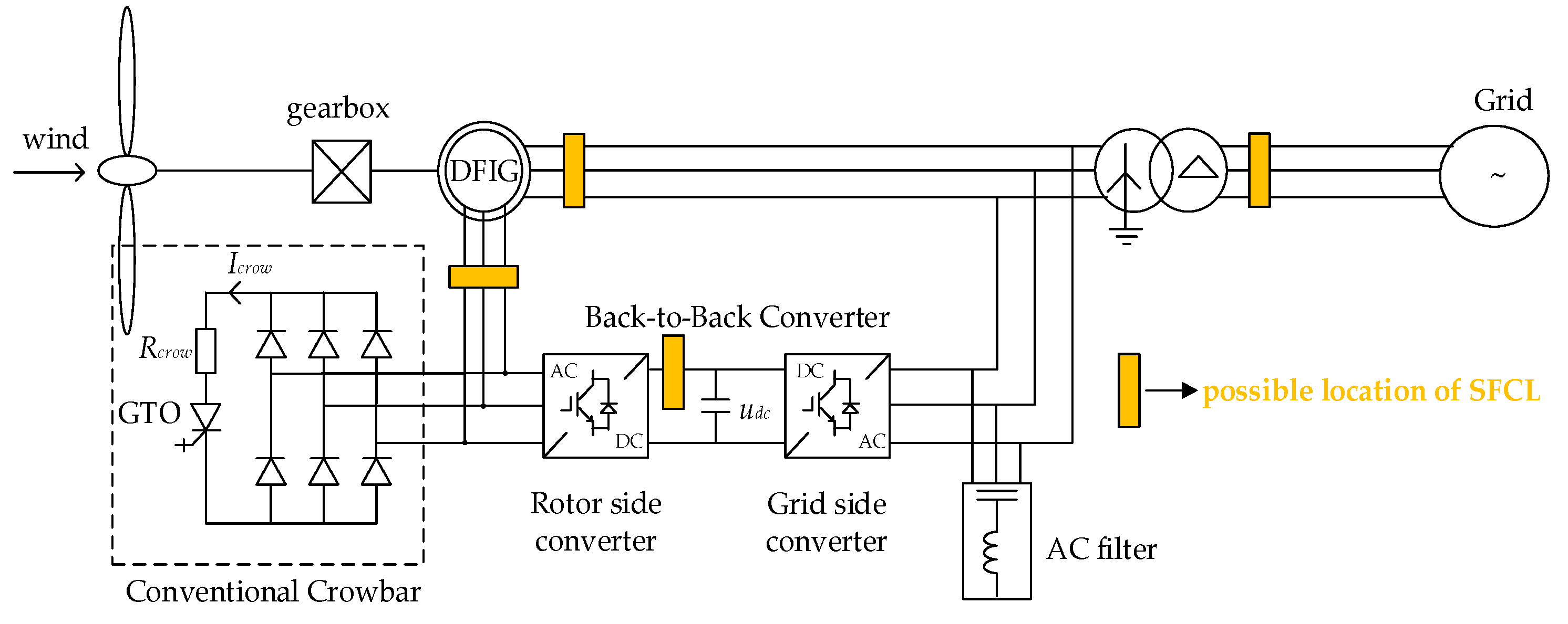
It can be noted that the most damage-prone element of the wind turbine set during fault cases is the power electronic converter. It has a limited operating range, and any exceedance of the permissible currents and voltages may lead to its destruction. As a result of the voltage drop in the grid, a large stator current is generated at the generator terminals. Due to the magnetic coupling between the stator and rotor windings, this current is transferred to the rotor circuit, posing a thermal threat to the converter. Moreover, the electromagnetic torque of the DFIG begins to oscillate with a large amplitude, causing mechanical stresses on the turbine. Additionally, a significant increase in the uDC voltage in the DC link is observed during fault cases. Hence, ensuring the wind turbine operates correctly in coordination with the grid (even during fault cases) and that the converter is adequately protected is critically important. To prevent damage to the converter, a crowbar system is installed on the rotor side [41,42,43,44,45]. The crowbar short-circuits the rotor winding through resistors, thereby limiting the rotor voltage and providing a safe path for the short-circuit current to flow (see Figure 2). When the amplitude of the rotor current exceeds the permissible value, the rotor side converter is disconnected, and the crowbar damping system is switched on [45,46]. The machine then operates as a squirrel-cage induction generator. The rotor remains short-circuited by the resistors until the short circuit is cleared or the main switch disconnects the stator from the grid [38].
The SFCL is a promising alternative to the crowbar, which requires a signal to initiate its operation after a short-circuit occurs. In the literature [21,22,23,24,25,26,27,28], descriptions of the use of SFCL for DFIG to limit short-circuit currents and facilitate compliance with LVRT requirements are provided, as well as analyses showing how the location of the short-circuit affects DFIG operation. Additionally, it is proposed to install the fault current limiter in four locations (see Figure 2), and various fault current limiter types are considered—extensive information can be found in [25]. However, there are no analyses regarding the permissible operating time of SFCL due to the use of HTS tapes. It is evident in Figure 1 that the DFIG must be connected during a short-circuit with a small voltage drop for more than 1.5 s. Consequently, the tapes may degrade as a result of long-term current flow with values exceeding the critical current. Therefore, the presented research results in this paper aimed to investigate how the operating time of SFCL affects the parameters of HTS tapes.
In the second situation, where SFCL can be exposed to the flow of short-circuit current for an extended period, there is a significant delay in switching off the short-circuit by the protection. A delay in the operation of the power system protection is used to ensure its selectivity. This is particularly evident in the overcurrent protection devices, which are used to detect short circuits and overloads in the power system. Generally, overcurrent relays can be categorized as instantaneous, definite time, or inverse definite minimum time (IDMT), where the last two may have very long delay operation times. In accordance with the inverse definite minimum time characteristic, the operating time of the relay decreases as the magnitude of the fault current increases, but it is never less than a predefined minimum time. IDMT operating characteristics are defined by the IEC 60255 standard [47] and the IEEE C37.112 standard [48]. The equations used to calculate the operating time according to the IEC 60255 standard are presented in Table 1, while characteristic curves are shown in Figure 3. It can be concluded that in this case, the SFCL may also be exposed to short-circuit current for an extended period before the protection with an IDMT characteristic detects the fault case and switches it off.
It can be concluded that the above-described cases show that SFCL can operate for long-duration short circuits. Therefore, in the next chapter, experimental testing of 2G HTSs (used in SFCL) is conducted, and the results are discussed.

3. Experimental Testing of 2G HTS Tape During Long-Duration Short Circuits

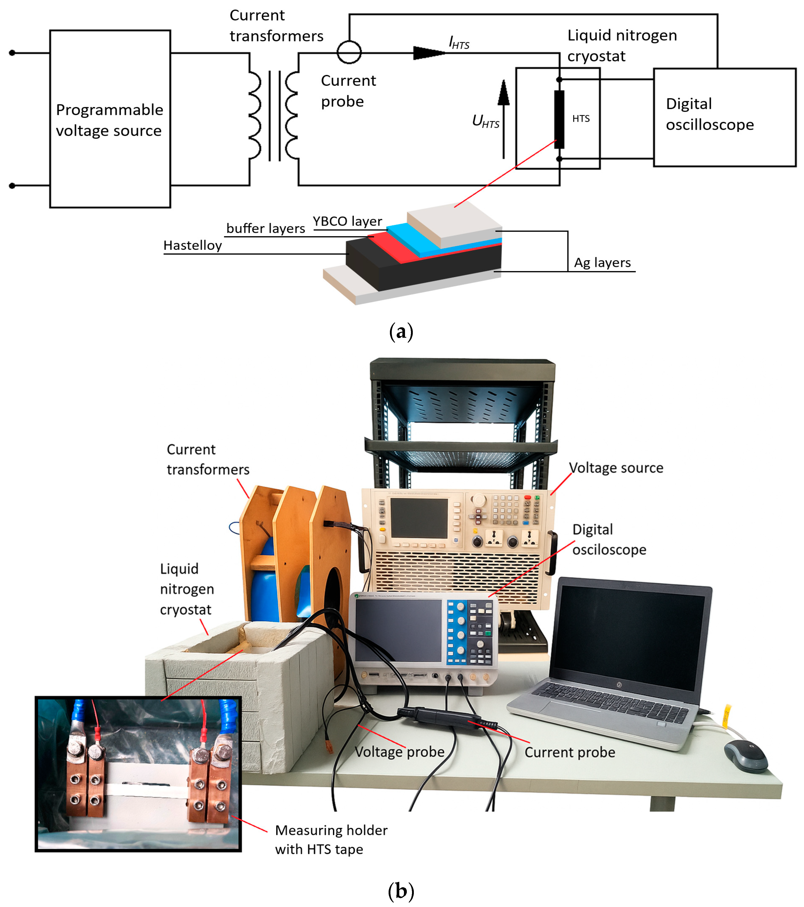
The functionality of HTS tape as a function of the duration of prospective short-circuit currents was tested for the SF12100-CF tape, which features a 2 µm silver layer, intended for the construction of the SFCL [49]. The tape parameters are given in Table 2. The structure of HTS 2G tapes from SuperPower (SuperPower Inc., Schenectady, NY, USA) is shown in Figure 4a. HTS tapes of the second generation (2G) feature a YBCO superconductor with a critical temperature of approximately 89 K [50]. These tapes are manufactured in the form of layered composite structures with a coated conductor, utilizing thin-film technology. It consists of a metal substrate made of stainless steel (Hastelloy C-276) with a thickness of 100 µm, buffer layers, and silver layers. The tape samples were cooled in a liquid nitrogen bath (77 K) under standard laboratory conditions, i.e., in a cryostat filled with liquid nitrogen to a level that completely covered the sample, at atmospheric pressure and without additional forced mixing. Convection and heat transfer occurred naturally, consistent with the typical boiling behavior of liquid nitrogen. The investigations were carried out on HTS tape samples with a length of 10 cm, subjected to test currents with durations of 0.5, 1, and 2 s, referred to as the test current.
It is worth noting that the voltage drop across the quenched region is also a significant parameter. The permissible value of voltage drops is a crucial design parameter that determines, among other things, the minimum length of tape required for the SFCL to ensure safe device operation. In [51], the allowable voltage drop was assumed to be 1 V/cm from a design perspective. Therefore, during the tests, voltage drop values were measured for three prospective short-circuit current values (640 A, 675 A, and 810 A), with the voltage drops remaining within a safe range. The maximum voltage drop value recorded was 0.58 V/cm. The prospective short-circuit current (Ispz) should be understood as the current that would flow in the given circuit if the superconductor did not limit it as a result of its transition to the resistive state.
The measurement system is shown in Figure 4. The measurements were performed using a Rohde & Schwarz RTB2004 digital oscilloscope (Rohde & Schwarz GmbH & Co. KG, Munich, Germany), equipped with a sampling frequency of 2.5 GSa/s and a vertical resolution of 10 bits. The time base was set in such a way that the recorded current impulse completely filled the oscilloscope acquisition window. The current was measured using a GMC-I Prosys CP1005 Hall-effect probe (GMC-I Messtechnik GmbH, Nürnberg, Germany)—sensitivity: 1 mV/A, bandwidth: 100 kHz, accuracy: ±1.5% of reading. The voltage across the tested tape sample was measured directly using measurement leads connected to the current terminals and attached to the oscilloscope. This arrangement enabled full reproduction of the instantaneous voltage waveforms, although the measurement accuracy was mainly limited by the resolution and linearity of the oscilloscope input channel (10 bits). The source of the test current was a programmable power supply, IT7626 (3 kVA), which provided a stable and repeatable waveform (accuracy: ±0.3% for AC current).
The main sources of measurement uncertainty were related to: (i) the limited bandwidth and resolution of the current probe (particularly during the fast current rise at the beginning of the impulse), (ii) the digital resolution of the oscilloscope (10 bits), and (iii) the thermal stability of the cryogenic environment. Considering the specified accuracies of the measuring equipment, it was estimated that the relative uncertainty of the instantaneous current and voltage measurements did not exceed ±3%. Consequently, the calculated values of the generated energy may be affected by a maximum error of about ±5%. This level of accuracy is sufficient to support the conclusions regarding the influence of short-circuit current duration on the degradation of the critical current (IC) value.
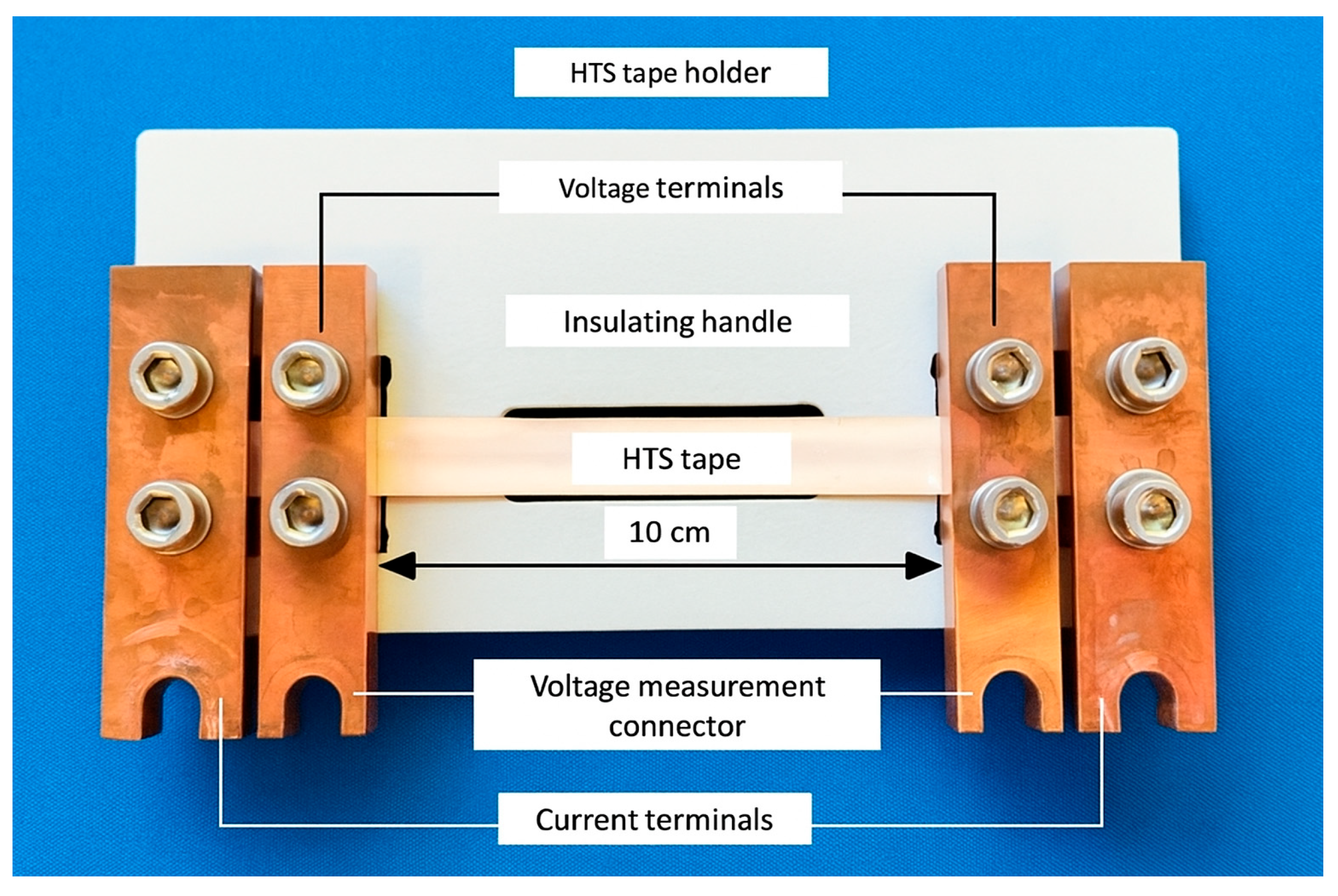
The method of mounting the HTS tape samples is illustrated in Figure 5. The tape samples were mounted in copper current terminals with a contact area of 240 mm2, which limited the current density at the contact and ensured stable electrical contact. The connection was made solely mechanically (without welding), and the condition of the contacts was verified by measuring the joint resistance: 85 µΩ at room temperature and 63 µΩ after cooling in liquid nitrogen (LN2). The contribution of the voltage drop at the contacts to the recorded signal was estimated at approximately 0.5%. The voltage drop was measured across the terminals of the measuring holder (see Figure 5).
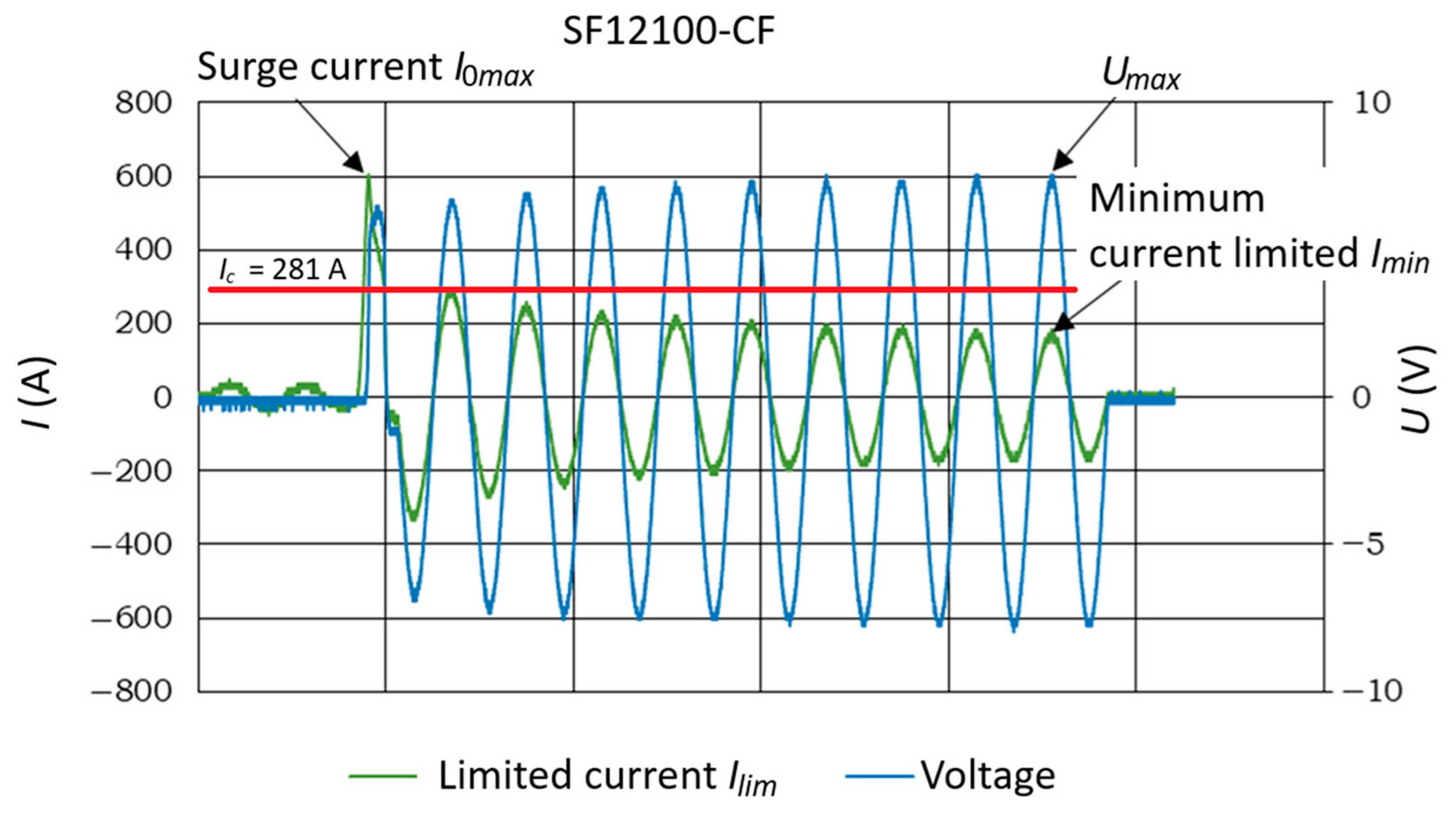
Figure 6 illustrates the principle of short-circuit limitation using a superconducting fault current limiter, with the recorded measurement values indicated. Once the test current reached a value corresponding to the critical current, the HTS tape transitioned to the resistive state. The highest instantaneous value of the short-circuit current, I0max, is referred to as the surge current. The current that flowed in the circuit in the resistive state was referred to as the limited short-circuit current, Ilim. The minimum value of the limited current, Imin, was assumed to be the value of the current amplitude at the end of the test, while Umax represented the maximum voltage on the HTS tape at the end of the test. After the transition to the resistive state, the voltage on the tape sample increased, and the current value decreased (Figure 6). Based on such observation, it is possible to detect when the tested tape undergoes a resistive state. The method used to determine the critical current during experimental tests is described in [49].
The value of estimated energy was analyzed during the experimental tests considered. Based on the measurement of instantaneous current and voltage values, the energy generated in the tape sample for different test impulse values was determined for the tested tapes. The following formula was used to calculate the energy value:
E = Δ t n k = 1 n u ( k ) i ( k )
where E—amount of energy generated on the tape sample, Δt—test duration, u—instantaneous value of the voltage on the tape, i—instantaneous value of current, n—number of samples during test, k—sample number.
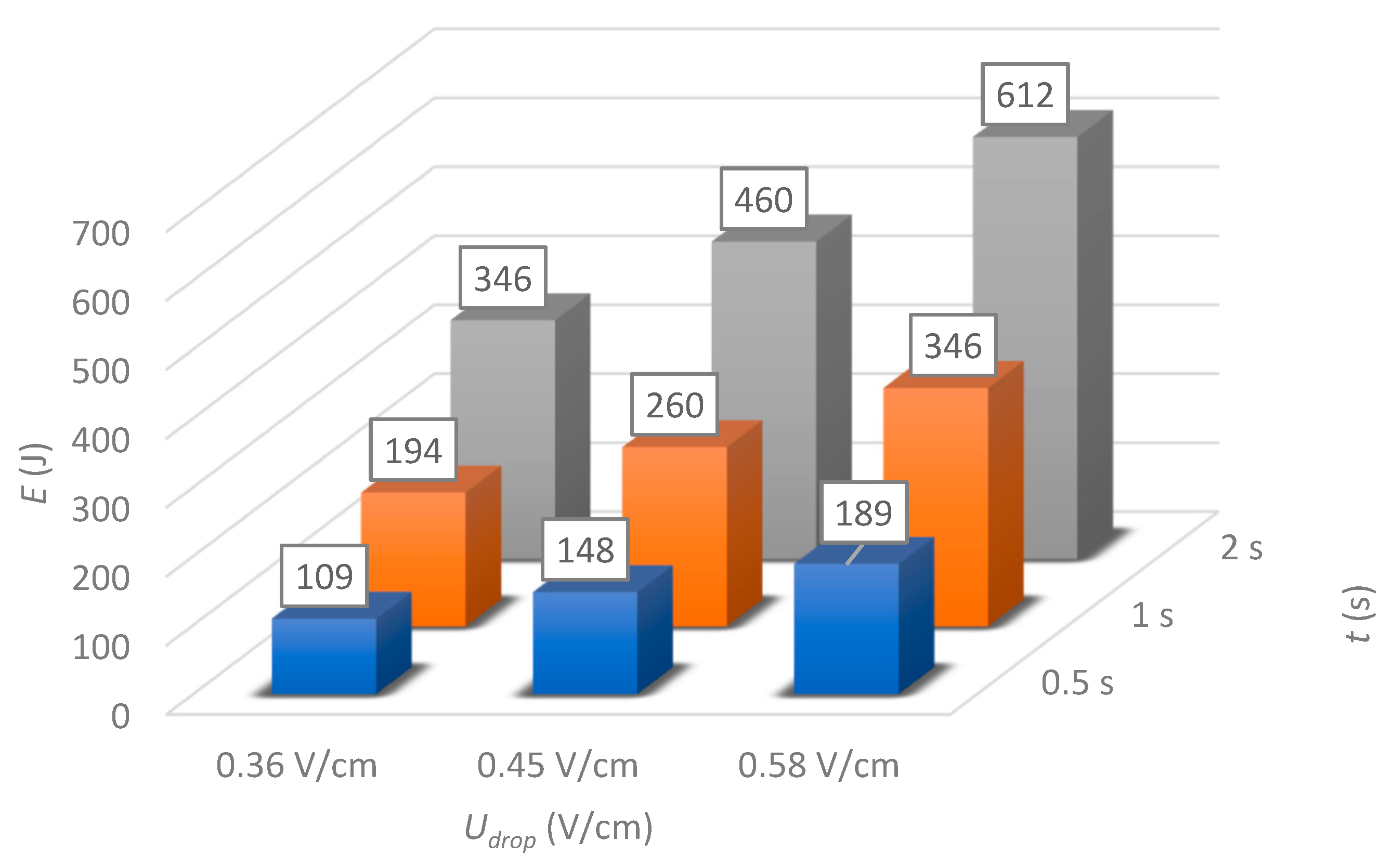
For the tested HTS tape, the values of energy E generated over time during the flow of test currents of different durations and at different voltage drop values were determined, as shown in Figure 6. The value of the voltage drop, 0.36 V/cm, was obtained for a test current of 640 A. For a voltage drop of 0.45 V/cm, the test current was 675 A, and for a voltage drop of 0.58 V/cm, the test current was 810 A. These values of energy generated are quickly converted into heat, resulting in temperature increases. It can be noted that in the resistive state, the short-circuit current flowing through the HTS tape (mostly silver layer [52], see Figure 4a) causes heating due to power losses in the resistance, as per the Joule-Lenz law. Only a small part of the current flows through the Hastelloy layer (Figure 4a) due to its higher resistance; therefore, the contribution of Hastelloy to heat generation is negligible.
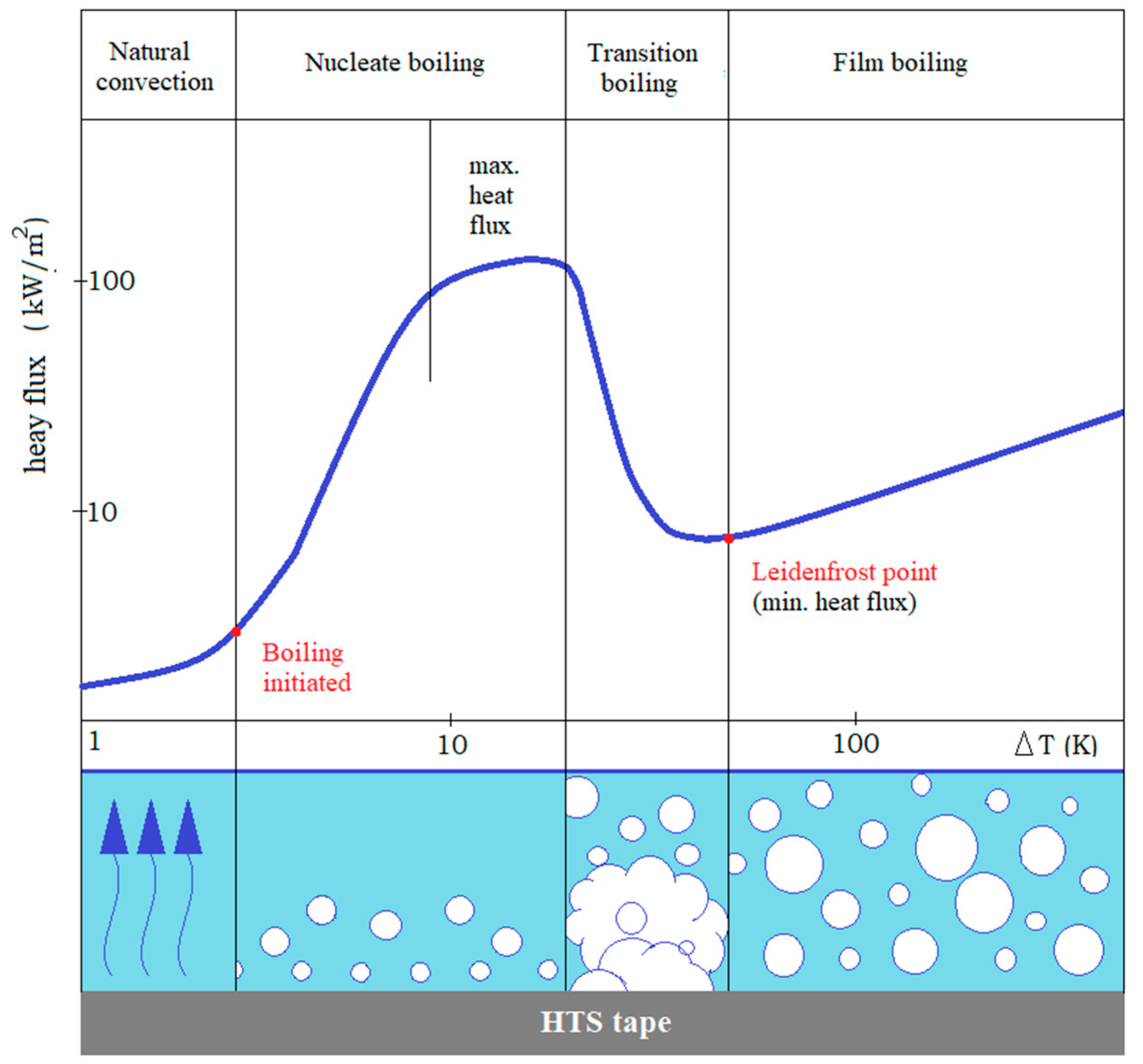
It can be expected that the heat generated in the non-insulated tape during quenching of the HTS tape is transferred into the cryogenic liquid (in this case, liquid nitrogen). Therefore, it can be assumed that the temperature of the HTS tape does not increase significantly. However, the intensity of dissipation of heat generated in the HTS tape into liquid nitrogen depends on the temperature difference between the tape sample surface and the liquid nitrogen [53], as shown in Figure 7.
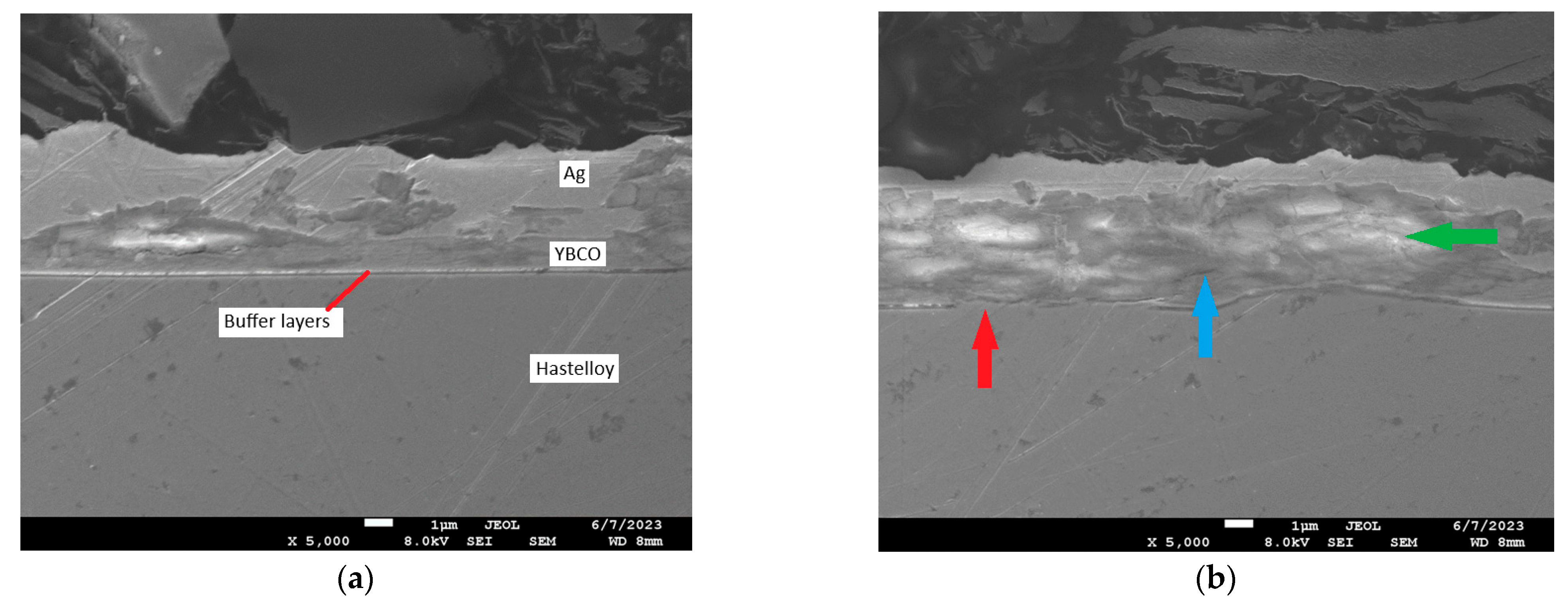
The heat exchange process between an HTS tape and liquid nitrogen occurs in four distinct phases: natural convection, nucleate boiling, transition boiling, and film boiling. At low temperature differences (∆T) between the HTS tape surface and the liquid nitrogen, heat generated within the conductor is transferred primarily through conduction into the cryogenic liquid. Simultaneously, the nitrogen above the tape heats up, decreases in density, and rises due to buoyant forces, releasing heat at the surface of the liquid through natural convection. When ∆T exceeds the onset temperature for boiling, nucleate boiling begins. At this stage, vapour bubbles of nitrogen start to form at the tape surface, grow, and detach. However, these vapour bubbles often condense before reaching the liquid surface, due to local thermal gradients. This phase is typically associated with the maximum heat transfer rate between the HTS conductor and the coolant, making it the most efficient cooling regime. As the temperature continues to rise, the system enters the transition boiling phase, which corresponds to a very narrow ∆T interval. During this unstable regime, heat transfer efficiency drops sharply. A thin and unstable vapour layer begins to form above the HTS surface, reducing the contact area between the liquid nitrogen and the conductor and severely impairing thermal conduction. Upon reaching the so-called Leidenfrost point, the system enters the film boiling phase. In this final stage, a stable vapour layer is maintained between the surface of the hot tape and the liquid nitrogen, acting as a thermal insulator and significantly hindering heat removal [54]. As a result, the temperature of the HTS tape increases. The rise in HTS tape temperature, along with the dynamic effects occurring during the limitation of short-circuit currents, may be responsible for the occurrence of micro-damages in the HTS tapes, such as delamination of tape layers, cracking of the superconducting layer, or, ultimately, destruction of the HTS tape itself. As demonstrated in our earlier works [55], microdamages in the structure of HTS tapes may include cracks in the YBCO layer, deformations in the buffer layers, and changes at the Ag-YBCO interface. Figure 8 presents exemplary microscopic images confirming the formation of degraded areas in the HTS tape: (a) a control sample of the tape, and (b) a sample after the recorded degradation, in which characteristic microstructural defects are visible—discontinuities of the buffer layers (red arrow), microcracks in the superconducting layers (blue arrow), and lighter areas in the superconducting layer (green arrow). A significant widening of the superconducting layer is also visible, which, as shown in [55], is related to diffusion processes.
Experimental tests were conducted on the HTS tape to determine whether the amount of generated energy and/or other parameters influence the degradation of the tape’s characteristics. Figure 9 shows how the amount of energy was generated in the HTS tape during the action of the test current for three different voltage drop values.
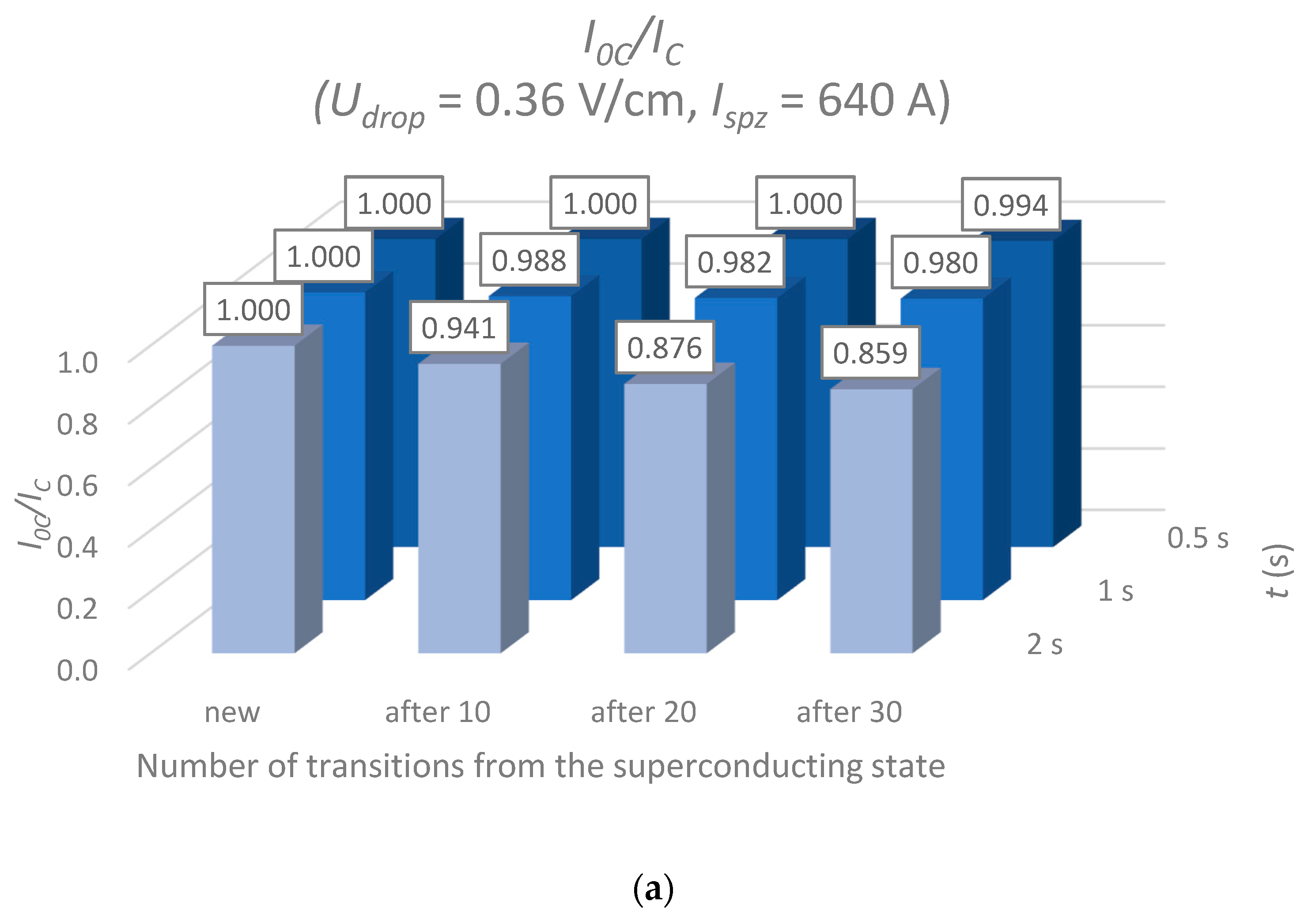
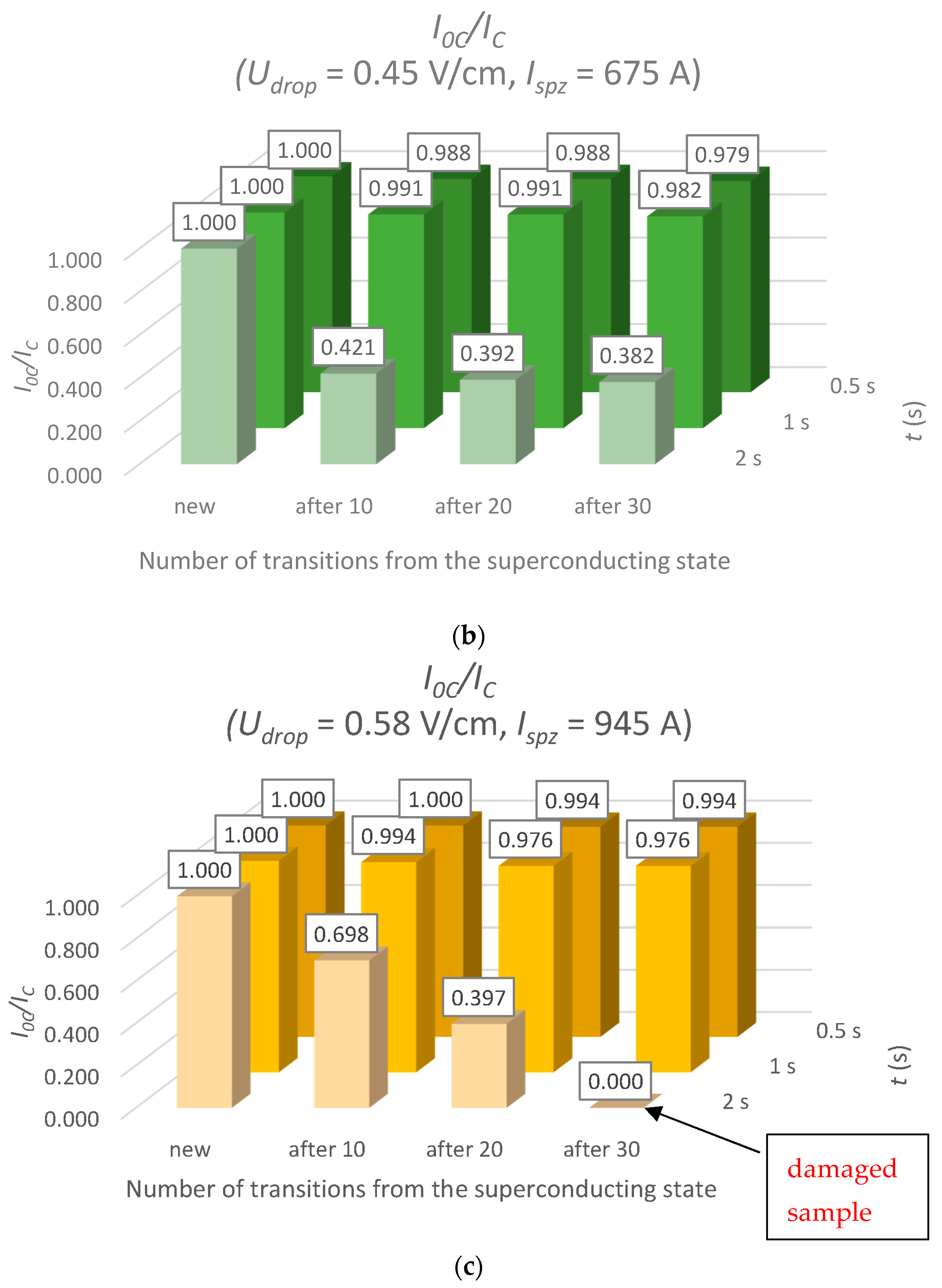
The tested HTS tape samples were driven out of the superconducting state using the test current. Between each quenching of the tape from the superconducting state, there was a break that allowed the tape sample to cool down and return to its thermal equilibrium state. The critical current (IC0) values were determined for a new, unused tape sample. Then, the tape sample was subjected to 10, 20, and 30 test currents, with the IC value measured after each series of tests. The IC/IC0 values are shown in Figure 10. Based on the tests, a decrease in the critical current value (a fundamental and crucial parameter of HTS tape) of the tape samples was observed, occurring with an increase in the test current impulse duration and voltage drops across the tape. For more extended test current durations, more energy was generated, and the tape sample heated up more. Heat transfer to liquid nitrogen may have been so inefficient that the tape sample reached high temperatures, potentially damaging the silver layer. On the surface of the damaged tape sample, damage spots were visible in the form of burnt points.
For the test current with a duration of 1 s and a voltage drop of 0.58 V/cm, and a 2 s test current duration and a voltage drop of 0.36 V/cm (see Figure 9), the energies generated on the tape samples were almost the same (346 J).
However, a greater decrease in the IC value was observed for the tape at the 2 s duration. This case demonstrates that the energy generated in the HTS tape sample does not fully reflect the degradation of the critical current. Furthermore, the test current and the voltage drop are not parameters that can be used as primary criteria for evaluating the degradation of the tape’s characteristics. The duration of the test current may have a decisive impact on the degradation of the IC value.
From the perspective of safe SFCL operation, the safe time that does not cause damage to the tape and degradation of the critical current, even after 30 transitions from the superconducting state, is 1 s. This means that the power system protection should be set to detect and switch off the short circuit within 1 s of its occurrence.
It can be concluded that even a small short-circuit current (here three times higher than the critical current) can cause damage to the tape if it flows for a sufficiently long time. This is an essential consideration because small short-circuit currents will be switched off by inverse time overcurrent protection with a long delay time. Additionally, the SFCL system used in a wind power plant with a doubly fed induction generator will also be exposed to long-term short-circuit current flow. In both cases, the protection settings should be selected (note that the selective operation condition must be maintained) so that the delay time is very short, less than 1 s. Switching off the short circuit within 1 s ensures the safe operation of the SFCL, which is installed in the DFIG or elsewhere in the power system. If the delay operation time of protection must be long (due to a selective operation condition), another possibility is bypassing the SFCL (before 1 s) with a conventional short-circuit current limiter (parallel reactors or a resistor).
A change in the critical current value of HTS tapes during SFCL operation is an undesirable phenomenon that requires continuous monitoring. Studies were conducted on the analyzed HTS tape to determine the occurrence of IC degradation based on observations of changes in the surge current and limited current values. It was observed that a decrease in the surge current value was recorded for tapes for which a reduction in the critical current value was identified. Lower IC values caused the tape to enter the resistive state more quickly; therefore, the surge current did not reach its original values. Observation of the value of I0max may serve as an initial criterion for assessing the decrease in the value of IC. A study was conducted to investigate the variability of surge current values as a function of the duration of prospective short-circuit currents. The values of the surge current were determined for a new tape sample, and then after 10, 20, and 30 transitions from the superconducting state with the test current. The values of I0max are presented in Table 3. In all cases, a correlation was observed between the decrease in the surge current value and the reduction in the critical current value. Similarly to the change in the value of IC (Figure 9), the most significant changes in the value of I0max were observed for the highest number of transitions of the HTS tape to the superconducting state and the test current duration of 2 s.
The dependence of changes in the value of the limited current was then analyzed. The minimum current values were measured for a new tape sample and subsequently after 10, 20, and 30 quenching cycles of the HTS tape. The results are shown in Table 4. The Imin values decrease with the duration of the test current on the tape sample, as the current is more limited over a longer time interval. The limiting current in the resistive state flows mainly through the silver layers (which determine the resistance of the tape); therefore, no correlation is observed here between the Imin value and the decrease in the critical current value.
Testing of voltage variation as a function of the duration of prospective short-circuit currents. During the test, the maximum voltage value that occurred on the tape sample in the resistive state was measured. The results of the measurements are shown in Table 5. Based on the tests conducted, it can be concluded that the Umax values did not generally change.

4. Discussion

In SFCL applications in which the HTS tape operates in the resistive regime, the time during which the sample accurately maintains its parameters, even when repeatedly driven out of the superconducting state, is of key importance. The voltage drop depends on the rated voltage of the system in which the SFCL operates. The voltage drop value in the SFCL can be selected by appropriately adjusting the length of the HTS tape. In the proposed experiment, tests were conducted for three values of voltage drop and three durations of the test current, yielding significant information regarding the resistance of HTS tapes to long-duration short-circuit currents in the context of their application in SFCL.
It was found that the critical factor influencing the degradation of the tape’s properties is not the amount of energy generated in the HTS tape nor the voltage drop, but primarily the duration of the test current. Even relatively low current values, only slightly exceeding the critical current, may lead to damage to the tape’s structure if they flow for too long. The studies showed that the safe operating time of the SFCL, during which the short-circuit current may flow through the HTS tape without causing irreversible degradation of its parameters, is about 1 s. From the perspective of reliable SFCL operation, this means that strict adherence to the time limitation of the device’s operation is required. When designing protection systems, it should be assumed that the short-circuit current must be detected and interrupted within one second to prevent a decrease in the critical current value. Failure to meet this condition may result in permanent damage to the tape or a shift in the operating point of the limiter, negatively affecting the selectivity and effectiveness of the protection system.
It has also been demonstrated in the literature that long-duration impulses lead to the build-up of thermal gradients and mechanical stresses between the layers of REBCO tapes, resulting in material fatigue, microcracks, and delamination [56]. Similarly, studies on coated conductors indicate that rapid thermal cycles and overheating promote layer separation and the degradation of electrical parameters [57]. Recent studies further confirm that the resistance of HTS tapes to long-duration fault loads is strongly dependent on the construction of the HTS tape and the cooling conditions. In [58], it was demonstrated that the type of tape insulation significantly affects the recovery time of the SFCL after a fault, confirming the necessity of limiting the impulse duration and selecting the conductor design appropriately. In [59], an asymmetric stabiliser structure of REBCO was proposed for resistive SFCLs, directly linking the limiting resistance and overcurrent endurance to the tape construction. In [60], it was shown that the presence of structural defects in HTS tapes significantly alters current distributions and losses in high-current stacks. These findings indicate that the duration of the overload is the key factor determining conductor durability, whereas the total amount of generated energy does not constitute a sufficient assessment criterion.
This issue becomes particularly significant in the context of modern generation sources, such as wind power plants with DFIGs, where LVRT requirements mandate maintaining the connection to the grid throughout the entire duration of the fault, which can last up to 3 s. In light of the obtained results, it should therefore be stated that standard approaches to protection system design, based on inverse time-current characteristics, are insufficient from the perspective of protecting superconducting components. They require modification by implementing a revised protection strategy that ensures a fast response (i.e., fault clearance in about 1 s) while still meeting the requirements of selective coordination. In cases where ultra-fast tripping is not feasible, an alternative solution is to automatically bypass the SFCL after 1 s using a conventional fault current limiting (FCL) device, such as a parallel inductor or a resistive bypass circuit. The proposed approach would enable the system to maintain continuous short-circuit current limitation without exceeding the thermal endurance limits of the superconducting tape. This hybrid system would be characterized by a long current-limiting time (an advantage of SFCL), zero steady-state losses (a disadvantage of FCL), and fast post-fault operation (a disadvantage of FCL). This concept will be further investigated to propose a final solution.
In the future, the following investigations should be pursued to extend and strengthen the current work. It is planned to consider multi-physics field modeling (which helps analyze electromagnetic, thermal, and mechanical phenomena) and monitoring methods for the in-service SFCL system (voltage, current, and sensors to determine the surface temperature of the tape). Additionally, experiments will be conducted with different long tapes and tapes from other manufacturers. Recommendations for power system protection should also be proposed (after multi-variant simulations) that ensure the safe operation of SFCL.

5. Conclusions

  • The operating time of the SFCL in the resistive state constitutes a key functional limitation of the device. The tested HTS tapes exhibit resistance to multiple transitions from the superconducting to the resistive state, provided that the duration of the short-circuit current does not exceed approximately 1 s—note that this time corresponds to the SF12100-CF tape with a thin layer of Ag; for other tape constructions, the safe time must be determined separately. Exceeding this time results in degradation of the critical current value (IC), which may consequently lead to accelerated activation of the SFCL (at lower short-circuit currents) or permanent damage to the tape.
  • From the perspective of operational diagnostics, the value of the surge current I0max can be used as an indicator of the deteriorating condition of the HTS tape. A decrease in the value of I0max in successive current-limiting cycles indicates an earlier transition of the tape to the resistive state, which in turn may result from the degradation of the critical current value.
  • To ensure the safe operation of SFCL in applications such as systems with DFIGs, it is first necessary to determine the safe operating time for the applied HTS tape based on experimental tests and analyses. Subsequently, it is recommended to implement a modified protection strategy that enables the detection and clearance of a fault in a time shorter than the established safe time (which, in the case of the tested HTS tape, was approximately 1 s). If this is not feasible, the SFCL should be automatically bypassed using a conventional fault current limiter once the permissible operating time is exceeded. Such an approach will allow the limiter to maintain continuous operation while avoiding the exceedance of the endurance limits of the HTS tape.

Author Contributions

Conceptualization, S.H., J.R. and K.S.; methodology, S.H., J.R. and K.S.; validation, S.H., J.R. and K.S.; formal analysis, S.H., J.R. and K.S.; investigation, S.H. and J.R.; data curation, A.K.; writing—original draft preparation, S.H., K.S.; writing—review and editing, A.K.; visualization, S.H., J.R. and K.S.; supervision, A.K.; project administration, S.H., J.R. and K.S. All authors have read and agreed to the published version of the manuscript.

Funding

This research was funded in whole or in part by the National Science Centre, Poland, 2024/53/B/ST8/01632.

Data Availability Statement

The original contributions presented in this study are included in the article. Further inquiries can be directed to the corresponding author.

Conflicts of Interest

Author Jacek Rusinski was employed by the company Ekoenergetyka–Polska S.A. The remaining authors declare that the research was conducted in the absence of any commercial or financial relationships that could be construed as a potential conflict of interest.

References

  1. Dias, D.H.N.; Sotelo, G.G.; Dias, F.J.M.; Rocha, L.M.M.; Matins, F.G.R.; Sass, F.; Polasek, A. Characterization of a Second Generation HTS Coil for Electrical Power Devices. IEEE Trans. Appl. Supercond. 2015, 25, 4601304. [Google Scholar] [CrossRef]
  2. Zhang, Y.; Lehner, T.F.; Fukushima, T.; Sakamoto, H.; Hazelton, D.W. Progress in Production and Performance of Second Generation (2G) HTS Wire for Practical Applications. IEEE Trans. Appl. Supercond. 2014, 24, 7500405. [Google Scholar] [CrossRef]
  3. Morandi, A.; Trevisani, L.; Fabbi, M.; Martini, L.; Bocchi, M. Superconducting transformer: Key design aspects for power applications. J. Phys. Conf. Ser. 2008, 97, 012318. [Google Scholar] [CrossRef]
  4. Hajiri, G.; Berger, K.; Trillaud, F.; Lévêque, J.; Caron, H. Impact of Superconducting Cables on a DC Railway Network. Energies 2023, 16, 776. [Google Scholar] [CrossRef]
  5. Peng, S.; Cai, C.; Cai, J.; Zheng, J.; Zhou, D. Optimum Design and Performance Analysis of Superconducting Cable with Different Conductor Layout. Energies 2022, 15, 8893. [Google Scholar] [CrossRef]
  6. Tsotsopoulou, E.; Dyśko, A.; Hong, Q.; Elwakeel, A.; Elshiekh, M.; Yuan, W.; Booth, C.; Tzelepis, D. Modelling and Fault Current Characterization of Superconducting Cable with High Temperature Superconducting Windings and Copper Stabilizer Layer. Energies 2020, 13, 6646. [Google Scholar] [CrossRef]
  7. Wojtasiewicz, G.; Janowski, T.; Kozak, S.; Kozak, J.; Majka, M.; Kondratowicz-Kucewicz, B. Experimental investigation of the model of superconducting transformer with the windings made of 2G HTS tape. IEEE Trans. Appl. Supercond. 2012, 22, 5500504. [Google Scholar] [CrossRef]
  8. Staines, M.P.; Jiang, Z.; Glasson, N.; Buckley, R.G.; Pannu, M. High-temperature superconducting (HTS) transformers for power grid applications. In Superconductors in the Power Grid: Materials and Applications; Woodhead Publishing: Cambridge, UK, 2015; pp. 367–397. [Google Scholar]
  9. Manusov, V.Z.; Nazarov, M.K. Design and Perspectives for Innovative Application of Power Transformers with a Superconducting Winding. In Proceedings of the 14th International Scientific-Technical Conference on Actual Problems of Electronic Instrument Engineering (APEIE), Novosibirsk, Russia, 2–6 October 2018; pp. 290–294. [Google Scholar]
  10. Liu, Y.; Grilli, F.; Cao, J.; Li, L.; Zhang, C.; Wang, M.; Xu, F.; Lin, J.; Noe, M. An Electromagnetic Design of a Fully Superconducting Generator for Wind Application. Energies 2021, 14, 7811. [Google Scholar] [CrossRef]
  11. Zhang, C.; Shen, L.; Wu, X.; Shan, F.; Chen, L.; Liu, S.; Zheng, Z.; Zhu, L.; Wang, J.; Zhai, Y. Review of Offshore Superconducting Wind Power Generation for Hydrogen Production. Energies 2025, 18, 1889. [Google Scholar] [CrossRef]
  12. Liu, B.; Badcock, R.; Shu, H.; Fang, J. A Superconducting Induction Motor with a High Temperature Superconducting Armature: Electromagnetic Theory, Design and Analysis. Energies 2018, 11, 792. [Google Scholar] [CrossRef]
  13. Hara, S.; Iwami, Y.; Kawasaki, R.; Matsumoto, T.; Shirai, Y.; Shiotsu, M.; Kobayashi, H.; Naruo, Y.; Nonaka, S.; Inatani, Y.; et al. Development of Liquid Hydrogen Cooling System for a Rotor of Superconducting Generator. IEEE Trans. Appl. Supercond. 2021, 31, 5202505. [Google Scholar] [CrossRef]
  14. Jacob, T.; Buchholz, A.; Noe, M.; Weil, M. Comparative Life Cycle Assessment of Different Cooling Systems for High-Temperature Superconducting Power Cables. IEEE Trans. Appl. Supercond. 2022, 32, 4802805. [Google Scholar] [CrossRef]
  15. Marchevsky, M. Quench Detection and Protection for High-Temperature Superconductor Accelerator Magnets. Instruments 2021, 5, 27. [Google Scholar] [CrossRef]
  16. Iwakuma, M.; Funaki, K.; Takeo, M.; Yamafuji, K. Quench protection of superconducting transformers. IEEE Trans. Magn. 1991, 27, 2080–2083. [Google Scholar] [CrossRef]
  17. Rao, V.V.; Kar, S. Superconducting Fault Current Limiters—A Review. Indian J. Cryog. 2011, 36, 14–25. [Google Scholar]
  18. Yadav, S.; Bharati, K.; Tewari, V. Sperconducting Fault Current Limiter—A Review. Int. J. Appl. Eng. Res. 2019, 14, 2. [Google Scholar]
  19. Nagarathna, M.C.; Murthy, H.V.; Shashikumar, R. A Review on Super Conducting Fault Current Limiter (SFCL) in Power System. Int. J. Eng. Res. Gen. Sci. 2015, 3, 485–489. [Google Scholar]
  20. Noe, M.; Steurer, M. High-temperature superconductor fault current limiters: Concepts, applications, and development status. Supercond. Sci. Technol. 2007, 20, R15. [Google Scholar] [CrossRef]
  21. Elshiekh, M.E.; Mansour, D.-E.A.; Azmy, A.M. Improving Fault Ride-Through Capability of DFIG-Based Wind Turbine Using Superconducting Fault Current Limiter. IEEE Trans. Appl. Supercond. 2013, 23, 5601204. [Google Scholar] [CrossRef]
  22. Zou, Z.C.; Chen, X.Y.; Li, C.S.; Xiao, X.Y.; Zhang, Y. Conceptual Design and Evaluation of a Resistive-Type SFCL for Efficient Fault Ride Through in a DFIG. IEEE Trans. Appl. Supercond. 2016, 26, 5600209. [Google Scholar] [CrossRef]
  23. Chen, L.; Li, G.; Chen, H.; Ding, M.; Zhang, X.; Li, Y.; Xu, Y.; Ren, L.; Tang, Y. Investigation of a Modified Flux-Coupling-Type SFCL for Low-Voltage Ride-Through Fulfillment of a Virtual Synchronous Generator. IEEE Trans. Appl. Supercond. 2020, 30, 5601006. [Google Scholar] [CrossRef]
  24. Yin, J.; Chen, Z.; Qian, W.; Zhou, S. A Virtual Synchronous Generator Low-Voltage Ride-Through Control Strategy Considering Complex Grid Faults. Appl. Sci. 2025, 15, 1920. [Google Scholar] [CrossRef]
  25. Naderi, S.B.; Davari, P.; Zhou, D.; Negnevitsky, M.; Blaabjerg, F. A Review on Fault Current Limiting Devices to Enhance the Fault Ride-Through Capability of the Doubly-Fed Induction Generator Based Wind Turbine. Appl. Sci. 2018, 8, 2059. [Google Scholar] [CrossRef]
  26. Zou, Z.-C.; Xiao, X.-Y.; Liu, Y.-F.; Zhang, Y.; Wang, Y.-H. Integrated Protection of DFIG-Based Wind Turbine with a Resistive-Type SFCL Under Symmetrical and Asymmetrical Faults. IEEE Trans. Appl. Supercond. 2016, 26, 5603005. [Google Scholar] [CrossRef]
  27. Zheng, Z.-X.; Huang, C.-J.; Yang, R.-H.; Xiao, X.-Y.; Li, C.-S. A Low Voltage Ride Through Scheme for DFIG-Based Wind Farm with SFCL and RSC Control. IEEE Trans. Appl. Supercond. 2019, 29, 5601005. [Google Scholar] [CrossRef]
  28. Ou, R.; Xiao, X.-Y.; Zou, Z.-C.; Zhang, Y.; Wang, Y.-H. Cooperative Control of SFCL and Reactive Power for Improving the Transient Voltage Stability of Grid-Connected Wind Farm with DFIGs. IEEE Trans. Appl. Supercond. 2016, 26, 5402606. [Google Scholar] [CrossRef]
  29. Lee, H.Y.; Asif, M.; Park, K.H.; Lee, B.W. Feasible Application Study of Several Types of Superconducting Fault Current Limiters in HVDC Grids. IEEE Trans. Appl. Supercond. 2018, 28, 5601205. [Google Scholar] [CrossRef]
  30. Lee, H.-Y.; Asif, M.; Park, K.-H.; Lee, B.-W. Assessment of appropriate SFCL type considering DC fault interruption in full-bridge modular multilevel converter HVDC system. Phys. C Supercond. Appl. 2019, 563, 1–6. [Google Scholar] [CrossRef]
  31. Xi, J.; Pei, X.; Song, W.; Niu, L.; Liu, Y.; Zeng, X. Integration of superconducting fault current limiter with solid-state DC circuit breaker. Int. J. Electr. Power Energy Syst. 2023, 145, 108630. [Google Scholar] [CrossRef]
  32. Reddy, S.R.P.; Kar, S.; Rajashekara, K. Resistive SFCL Integrated Ultra-Fast DC Hybrid Circuit Breaker for Subsea HVDC Transmission Systems. In Proceedings of the 2021 IEEE Industry Applications Society Annual Meeting (IAS), Vancouver, BC, Canada, 10–14 October 2021; pp. 1–6. [Google Scholar]
  33. Suarez, P.; Alvarez, A.; Ceballos, J.M.; Perez, B. Loss and Transition Studies of Shunted Free-Stabilized YBCO Tape for SFCL Applications. IEEE Trans. Appl. Supercond. 2011, 21, 1267–1270. [Google Scholar] [CrossRef]
  34. Kwon, N.Y.; Kim, H.S.; Kim, K.L.; Yim, S.W.; Kim, H.-R.; Hyun, O.-B.; Kim, H.M.; Lee, H.G. Influence of stabilizer thickness on over-current test of YBCO-coated conductors. Supercond. Sci. Technol. 2009, 22, 045033. [Google Scholar] [CrossRef]
  35. Amaro, N.; Souc, J.; Vojenciak, M.; Pina, J.M.; Martins, J.; Ceballos, J.M.; Gomory, F. AC Losses and Material Degradation Effects in a Superconducting Tape for SMES Applications. In Proceedings of the 5th IFIP WG 5.5/SOCOLNET Doctoral Conference on Computing, Electrical and Industrial Systems, DoCEIS 2014, Costa de Caparica, Portugal, 7–9 April 2014. [Google Scholar]
  36. Yazaki, S.; Karasawa, A.; Kotoyori, T.; Ishiyama, A.; Miyahara, N. Critical Current Degradation in High-Temperature Superconducting Tapes Caused by Temperature Rise. IEEE Trans. Appl. Supercond. 2013, 23, 4602304. [Google Scholar] [CrossRef]
  37. Dongdong, L. A combined protection and control strategy to enhance the LVRT capability of a wind turbine driven by DFIG. In Proceedings of the 2nd IEEE International Symposium on Power Electronics for Distributed Generation Systems, Hefei, China, 16–18 June 2010. [Google Scholar]
  38. El-Sattar, A.A.; Saad, N.H.; El-Dein, S. Dynamic response of doubly fed induction generator variable speed wind turbine under fault. Electr. Power Syst. Res. 2008, 78, 1240–1246. [Google Scholar] [CrossRef]
  39. Erlich, I.; Wrede, H.; Feltes, S. Dynamic behavior of DFIG-based wind turbines during grid faults. IEEJ Trans. Ind. Appl. 2008, 128, 396–401. [Google Scholar] [CrossRef]
  40. Rusiński, J. Impact of Superconducting Fault Current Limiter on the Distributed Energy Source Work. IET Gener. Transm. Distrib. 2017, 12, 310–317. [Google Scholar] [CrossRef]
  41. Hansen, A.D.; Michalke, G. Fault ride-through capability of DFIG wind turbines. Renew. Energy 2007, 32, 1594–1610. [Google Scholar] [CrossRef]
  42. Wessels, C.; Fuchs, F.W. Fault ride through of DFIG wind turbines during symmetrical voltage dip with crowbar or stator current feedback solution. In Proceedings of the Energy Conversion Congress and Exposition (ECCE), Atlanta, GA, USA, 12–16 September 2010. [Google Scholar]
  43. Morren, J.; De Haan, S.W.H. Short-circuit current of wind turbines with doubly fed induction generator. IEEE Trans. Energy Convers. 2007, 22, 174–180. [Google Scholar] [CrossRef]
  44. Petersson, A.; Lundberg, S.; Thiringer, T. A DFIG wind turbine ride-through system. Influence on the energy production. Wind Energy 2005, 8, 251–263. [Google Scholar] [CrossRef]
  45. Seman, S.; Iov, F.; Niiranem, J.; Arkkio, A. Comparison of simulations for variable-speed wind turbine transient analysis. Int. J. Energy Res. 2006, 30, 713–728. [Google Scholar] [CrossRef]
  46. Sun, T.; Chen, Z.; Blaabjerg, F. Voltage recovery of grid-connected wind turbines with DFIG after a short-circuit fault. In Proceedings of the 35th Annual IEEE Power Electronics Specialists Conference, Aachen, Germany, 20–25 June 2004. [Google Scholar]
  47. IEC 60255; Standard for Electrical Relays. The International Electrotechnical Commission (IEC): Geneva, Switzerland, 1989.
  48. IEEE C37.112-2018; IEEE Standard for Inverse-Time Characteristics Equations for Overcurrent Relays. IEEE: Piscataway, NJ, USA, 2019. [CrossRef]
  49. Hajdasz, S.; Kempski, A.; Solak, K.; Marc, M.; Rusinski, J.; Szczesniak, P. Critical Current Degradation in HTS Tapes for Superconducting Fault Current Limiter under Repeated Overcurrent. Appl. Sci. 2023, 13, 4323. [Google Scholar] [CrossRef]
  50. Surdacki, P. The Quench Parameter Analysis of YBCO and MgB2 Superconducting Wires. Electrotech. Rev. 2014, 90, 16–19. [Google Scholar]
  51. Available online: https://www.superpower-inc.com/specification.aspx (accessed on 15 December 2023).
  52. Kar, S.; Rao, V.V. Step-by-step design of a single phase 3.3 kV/200 A resistive type superconducting fault current limiter (R-SFCL) and cryostat. Phys. C Supercond. Its Appl. 2018, 550, 107–116. [Google Scholar] [CrossRef]
  53. Buchmuller, I. Influence of Pressure on Leidenfrost Effect; Technische Universität: Darmstadt, Germany, 2014. [Google Scholar]
  54. Talari, V.; Behar, P.; Lu, Y.; Haryadi, E.; Liu, D. Liedenfrost drops on micro/nanostructured surfaces. Front. Energy 2018, 12, 22–42. [Google Scholar] [CrossRef]
  55. Hajdasz, S.; Kempski, A.; Arkusz, K.; Szczesniak, P. The Identification of Microstructural Changes in High-Temperature Superconducting Tapes for Superconducting Fault Current Limiters. Appl. Sci. 2024, 14, 9520. [Google Scholar] [CrossRef]
  56. Zhou, Y.-H.; Park, D.; Iwasa, Y. Review on progresses and challenges of key mechanical issues in high-field superconducting magnets. Natl. Sci. Rev. 2023, 10, nwad001. [Google Scholar] [CrossRef] [PubMed]
  57. Yin, S.; Duranti, M.; Swenson, C.A.; Li, P.; Ye, L.; Zhang, X.; Shen, T. Degradation of REBCO coated conductors due to a combination of epoxy impregnation, thermal cycles, and quench: Characteristics and a method of alleviation. J. Appl. Phys. 2020, 128, 173903. [Google Scholar] [CrossRef]
  58. Kozak, J. Effect of Tape Insulation on Recovery Time of a Conduction-Cooled Resistive Superconducting Fault Current Limiter. Energies 2024, 17, 3350. [Google Scholar] [CrossRef]
  59. Li, M.; Chen, Y. An Asymmetric Stabilizer Layer Structure of REBCO Superconducting Tapes for Resistive Superconducting Fault Current Limiters. Cryogenics 2024, 138, 103791. [Google Scholar] [CrossRef]
  60. Chen, B.; Li, J.; Xu, M.; Gao, S. Modeling of HTS High-Current Stacked Conductors with Defective Tapes in Different Locations. Phys. C Supercond. Its Appl. 2023, 606, 135431. [Google Scholar] [CrossRef]
Figure 1. Examples of LVRT characteristics [40].
Energies 18 05302 g001
Figure 2. Scheme of a wind turbine with a crowbar system and possible location of SFCL.
Energies 18 05302 g002
Figure 3. IDMT relay characteristics according to the IEC 60255 standard for TMS = 1.
Energies 18 05302 g003
Figure 4. Measurement system: (a) measurement system scheme, (b) view of the measurement station.
Energies 18 05302 g004
Figure 5. Method of attaching HTS tapes to the measuring holder.
Energies 18 05302 g005
Figure 6. Current and voltage oscillograms of the HTS 2G tape illustrating the principle of short-circuit limitation by SFCL.
Energies 18 05302 g006
Figure 7. Characteristics of heat transfer between the HTS tape surface and liquid nitrogen as a function of temperature [53].
Energies 18 05302 g007
Figure 8. SEM images confirming the formation of degraded areas in the HTS tape: (a) control sample of the tape, and (b) sample after the recorded degradation, in which characteristic microstructural defects are visible.
Energies 18 05302 g008
Figure 9. The values of energy generated on the HTS tape as a function of short-circuit duration time and voltage drop.
Energies 18 05302 g009
Figure 10. Variation in the critical current value as a function of the test current and different time durations: (a) Udrop = 0.36 V/cm, (b) Udrop = 0.45 V/cm, (c) Udrop = 0.58 V/cm.
Energies 18 05302 g010aEnergies 18 05302 g010b
Table 1. IEC 60255 standard characteristic [47].
Relay CharacteristicEquation
Standard Inverse (SI) t = T M S 0.14 I r 0.02 1
Very Inverse (VI) t = T M S 13.5 I r 1
Extremely Inverse (EI) t = T M S 80 I r 2 1
where Ir = (I/Is), Is is the relay setting current, I is the measured current, and TMS is the time multiplier setting.
Table 2. Parameters of the tested tapes [51].
TapeSF12100-CF
the thickness of the silver layer2 μm
width12 mm
thickness0.105 mm
substrate thickness (Hastelloy)0.1 mm
minimum critical current ICmin (77 K)281 A
length of the tested tape 10 cm
Table 3. Surge current values.
I0max (A)
t (s)Udrop = 0.36 V/cmUdrop = 0.45 V/cmUdrop = 0.58 V/cm
NewAfter 10After 20After 30NewAfter 10After 20After 30NewAfter 10After 20After 30
0.5480.0480.0480.0476.6523.3496.6496.6496.6536.6536.6533.3533.3
1476.6473.3473.3433.0520.0510.0510.0513.3543.3540.0533.3533.3
2470.0400.0373.0366.0520.0386.6370.0363.0550.0380.0366.6- *
* damaged sample.
Table 4. Changes in the value of the minimum limited current.
Imin (A)
t (s)Udrop = 0.36 V/cmUdrop = 0.45 V/cmUdrop = 0.58 V/cm
NewAfter 10After 20After 30NewAfter 10After 20After 30NewAfter 10After 20After 30
0.5120.0123.3123.3123.3126.6130.0130.0130.0130.0126.6126.6130.0
1113.3116.6116.6113.3113.3113.3113.3113.3106.6106.6106.6106.6
296.796.796.796.7106.6100.096.796.7106.6106.6106.6- *
* damaged sample.
Table 5. Maximum voltage values on the HTS tape.
Umax (V)
t (s)Udrop = 0.36 V/cmUdrop = 0.45 V/cmUdrop = 0.58 V/cm
NewAfter 10After 20After 30NewAfter 10After 20After 30NewAfter 10After 20After 30
0.53.53.63.53.64.44.34.44.35.45.35.45.3
13.63.63.63.64.54.54.54.55.85.75.65.7
23.63.63.63.64.74.84.74.75.75.75.7- *
* damaged sample.
Disclaimer/Publisher’s Note: The statements, opinions and data contained in all publications are solely those of the individual author(s) and contributor(s) and not of MDPI and/or the editor(s). MDPI and/or the editor(s) disclaim responsibility for any injury to people or property resulting from any ideas, methods, instructions or products referred to in the content.