Article

Efficient Autonomy: Autonomous Driving of Retrofitted Electric Vehicles via Enhanced Transformer Modeling

1
School of Mechanical Science and Engineering, Huazhong University of Science and Technology, Wuhan 430074, China
2
School of Mechanical Engineering, Ningxia University, Yinchuan 750021, China
*
Author to whom correspondence should be addressed.
Energies 2025, 18(19), 5247; https://doi.org/10.3390/en18195247
Submission received: 27 August 2025 / Revised: 26 September 2025 / Accepted: 29 September 2025 / Published: 2 October 2025
(This article belongs to the Section E: Electric Vehicles)

Abstract

In low-risk and open environments, such as farms and mining sites, efficient cargo transportation is essential. Despite the suitability of autonomous driving for these environments, its high deployment and maintenance costs limit large-scale adoption. To address this issue, a modular unmanned ground vehicle (UGV) system is proposed, which is adapted from existing platforms and supports both autonomous and manual control modes. The autonomous mode uses environmental perception and trajectory planning algorithms for efficient transport in structured scenarios, while the manual mode allows human oversight and flexible task management. To mitigate the control latency and execution delays caused by platform modifications, an enhanced transformer-based general dynamics model is introduced. Specifically, the model is trained on a custom-built dataset and optimized within a bicycle kinematic framework to improve control accuracy and system stability. In road tests allowing a positional error of up to 0.5 m, the transformer-based trajectory estimation method achieved 94.8% accuracy, significantly outperforming non-transformer baselines (54.6%). Notably, the test vehicle successfully passed all functional validations in autonomous driving trials, demonstrating the system’s reliability and robustness. The above results demonstrate the system’s stability and cost-effectiveness, providing a potential solution for scalable deployment of autonomous transport in low-risk environments.

1. Introduction

With the rapid evolution of artificial intelligence, networked systems, sensor technologies, and data analytics, autonomous driving has progressed from a conceptual framework to a pilot-scale deployment. It now demonstrates tangible engineering viability in a low-risk operational environment. Nonetheless, technological advancement alone does not ensure universal applicability. Current autonomous driving systems face critical limitations, including opaque regulatory landscapes, insufficient hazard recognition capabilities, and inadequate robustness under complex driving conditions—all of which impede scalable deployment in real-world traffic environments. Empirical evidence suggests that accident rates for autonomous vehicles significantly exceed those of human drivers under challenging conditions such as poor lighting or sharp turns. For instance, under low-visibility conditions such as dawn or dusk, autonomous driving systems (ADSs) exhibit an accident occurrence rate that is 5.25 times higher than that of human-driven vehicles (HDVs). In turning scenarios, the rate remains elevated at 1.988 times that of HDVs [1]. Moreover, the scarcity of critical safety incidents severely restricts the generalization power of deep learning models, exacerbating uncertainty in dynamic and unstructured settings [2]. In contrast, deployment in controlled open environments—such as agricultural fields or mining zones—offers promising engineering feasibility. Here, safety demands are comparatively lower, and autonomous systems can alleviate labor shortages while enhancing logistical efficiency. One notable implementation is the autonomous excavation system proposed in [3], which combines multimodal sensing and hierarchical task planning to enable continuous and efficient operations in harsh field conditions. This exemplifies the system’s stability and adaptability when exposed to environmental extremes. Extending mature autonomous platforms to open-field applications not only boosts operational performance but also contributes to green mobility. Through intelligent scheduling and energy optimization, such systems promote resource-efficient workflows and actively support low-carbon development initiatives.
While modern electric vehicles increasingly rely on high-precision sensors and high-performance computing units—such as multi-layer LiDAR, RTK-GNSS modules, and embedded platforms—to ensure operational safety, the associated hardware costs remain significantly elevated, making them unsuitable for deployment in cost-sensitive logistics applications. This issue is particularly pronounced in large-scale implementations, where proprietary autonomous driving systems often are constrained by limited flexibility and excessive cost, impeding third-party evaluation and optimization of algorithms and system performance (see, for instance, open-access initiatives based on commercial platforms, such as the ZMP Robocar HV [4]). Consequently, balancing the trade-off between maintaining essential autonomous driving capabilities and controlling overall system cost has emerged as a critical challenge in promoting scalable and economically viable autonomous solutions.
To address these limitations, recent studies have proposed lightweight control strategies and structural optimization techniques—including sparse perception modeling [5,6], vectorized scene representation [7], and end-to-end control frameworks [8,9]—to enhance trajectory tracking capabilities on low-cost platforms. Building on this research landscape, the present study adopts the Model Predictive Path Integral (MPPI) algorithm [10,11,12] as the core control strategy. As a sampling-based model predictive control approach, MPPI enables efficient trajectory optimization in high-dimensional state spaces through a path integral formulation. It offers notable advantages in robustness and computational efficiency, making it particularly suitable for dynamic control tasks on low-resource systems. The proposed control framework effectively balances system responsiveness and tracking accuracy, significantly improving trajectory stability under challenging operating conditions.
In recent years, path planning and trajectory tracking have expanded from structured roads to complex, dynamic scenarios. In urban traffic (e.g., intersections, narrow passages, mixed flows) [13], planning algorithms enhance vehicle maneuverability and safety. Meanwhile, in industrial/semi-structured settings (e.g., mobile robots, low-speed platforms) [14], these techniques enable stable task execution under resource constraints. For low-risk open areas (e.g., agricultural fields, mining zones), simple environmental structures and minimal traffic interactions facilitate autonomous deployment; yet challenges like uneven terrain, irregular obstacles, and limited perception fidelity constrain reliability. To address these challenges, a proposed modular UGV platform for low-cost applications integrates lightweight planning algorithms with a robust trajectory-tracking framework, enabling efficient navigation across heterogeneous hardware. The architecture emphasizes flexible sensor integration, computational load balancing, and environmental adaptability, providing a scalable foundation for agricultural automation and mining transport.
Although the aforementioned control strategies demonstrate promising performance in terms of path-tracking accuracy and responsiveness, their practical effectiveness remains constrained under specific platform conditions. This limitation becomes particularly pronounced in real-world scenarios involving retrofitted vehicle architectures subject to substantial payload fluctuations, where model adaptability poses a critical challenge. In existing studies on autonomous driving control systems, the majority of control models are grounded in the kinematics and dynamics of robotic or vehicular platforms [15,16]. However, their applicability is significantly constrained within the operational context explored in this study. Specifically, the vehicle platform employed herein is tasked with frequent cargo transportation, resulting in frequent and unpredictable payload variations that significantly affect the vehicle’s dynamic response characteristics. More critically, the control system is retrofitted onto an existing vehicle rather than developed as an integrated native platform, which inherently introduces control latency and actuation lag within the system architecture.
To address control latency and dynamic response variability in retrofitted vehicle platforms, recent studies have integrated machine learning (ML) techniques to enhance system adaptability and robustness. Specifically, CNNs and RNNs detect sensor faults and actuator anomalies, improving safety and fault tolerance [17]; reinforcement learning (RL) adapts policies in dynamic environments, enabling efficient decision-making under complex traffic conditions [18].
Building upon these developments, transformer-based architectures have recently gained traction in robotics and autonomous driving, owing to their superior capabilities in modeling long-range temporal dependencies and extracting expressive representations from sequential data. Unlike traditional physics-based kinematic or dynamic models, transformers are particularly effective in capturing long-range temporal dependencies from sequential data, making them well-suited for fitting complex, non-linear vehicle motion behaviors. As shown in [19], a transformer-based multi-agent trajectory prediction method was introduced to improve prediction accuracy by modeling spatiotemporal interactions among autonomous vehicles. In [20], transformer dynamics modeling was combined with autoregressive Q-learning to enable precise short-term state prediction in planning scenarios. Moreover, recent advancements, such as the State Estimation Transformer architecture proposed in [21], have demonstrated high-fidelity inference of latent robot states through conditional sequence modeling, particularly excelling in dynamic locomotion tasks. Collectively, these contributions underscore the efficacy of attention-based temporal modeling frameworks in capturing complex motion dynamics from data. They further validate the adoption of transformer-based architectures as a principled approach for modeling vehicle dynamics in data-driven settings.
The modeling capabilities of transformer architectures have prompted growing interest in their deployment for real-world vehicle control applications. To address challenges such as fluctuating payload conditions, hardware heterogeneity, and communication latency—which collectively degrade control precision and real-time responsiveness—this study adopts the transformer-based control modeling framework proposed in [22]. Using its advanced temporal encoding capacity and global attention mechanisms, the framework effectively extracts rich dynamic representations from input sequences that comprise historical states, action histories, and anticipated control commands. This enables more accurate and stable trajectory regulation under uncertain operating conditions. Furthermore, the architecture’s adaptability to high-dimensional sensor inputs and its proficiency in capturing nonlinear system behavior position it as a promising solution for control tasks on retrofitted platforms.
Existing retrofittable autonomous driving systems often suffer from high implementation costs, complex integration procedures, and limited deployment flexibility, rendering them impractical for widespread use—particularly in low-risk, open environments such as farms and mining sites. Addressing this gap, this paper introduces a modular unmanned ground vehicle system featuring dual-mode control (autonomous and manual) and a distributed algorithmic framework, designed to enhance both cost-efficiency and deployment adaptability. The proposed system achieves effective coordination between path planning and motion control under resource-constrained hardware conditions. Furthermore, by integrating deep temporal modeling with classical vehicle dynamics, it captures the nonlinear behavior inherent to retrofitted platforms with greater fidelity. This approach significantly improves trajectory tracking accuracy and control robustness, offering a viable and scalable solution for low-cost autonomous vehicle retrofitting. To elaborate on the system’s architecture and implementation, the remainder of this paper is organized as follows: Firstly, the trajectory output module (discussed in Section 2.3 Device Planner) generates speed and angular velocity control commands. These messages are then processed by the dynamics model (discussed in Section 3 BicycleAnyCar Model) into vehicle speed and steering control messages, which are sent to the vehicle controller (discussed in Section 2.2, Device Controller). Finally, the vehicle controller regulates the car base. Additionally, sensor data is processed by the bicycle model to provide feedback on the vehicle’s status. The entire autonomous driving system architecture is shown in Figure 1.

2. Design and Development of an Autonomous Driving System

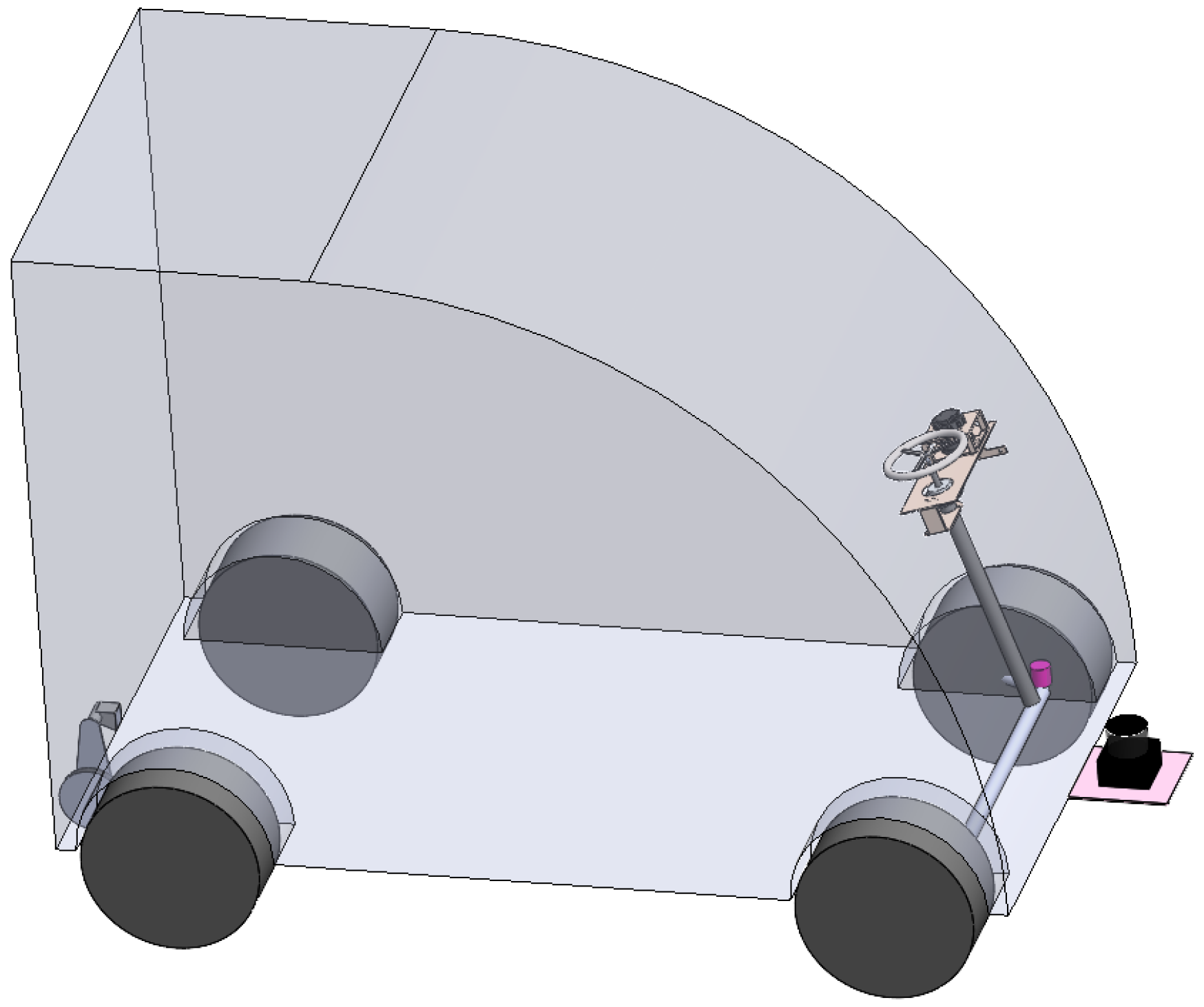
This section addresses the design of devices, including modifications to actuators and the integration of additional sensors. Specifically, the actuators comprise the accelerator pedal, brake, steering wheel, and gear shifter, while the sensor suite includes an IMU, odometer, angular position sensors, and lidar. The assembly diagram is shown in Figure 2.

2.1. Device Description

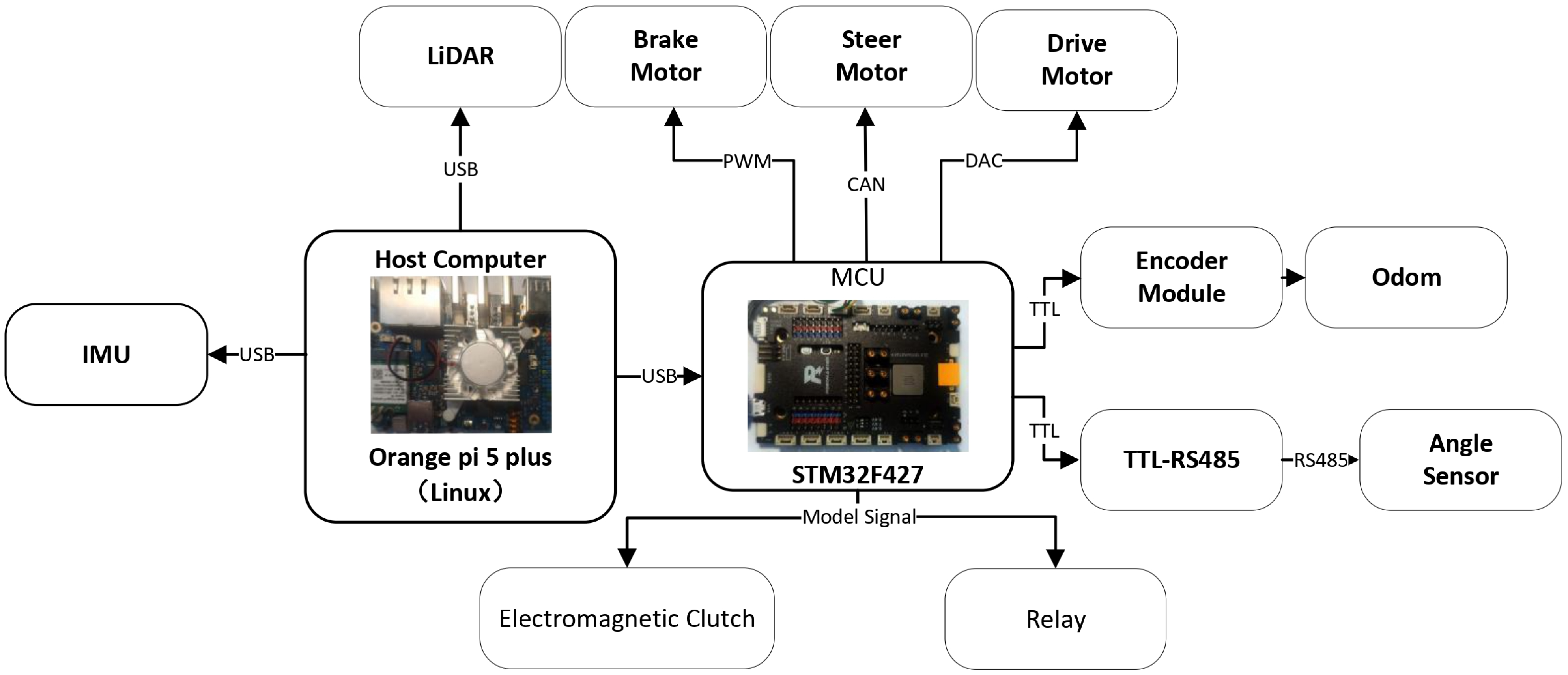
Autonomous vehicle control can be progressively realized through modular retrofitting of existing manually operated platforms. This process entails systematic modification and actuation of independently controllable subsystems, including throttle, steering, braking, and gear-shifting mechanisms. Consideration must also be given to the mode transition between manual and autonomous driving states. The configuration and integration of all relevant actuators are depicted in Figure 3. Furthermore, sensor modules play a critical role in enabling feedback-driven control and system state awareness; their design and implementation will be elaborated upon in subsequent sections.

2.1.1. Steering Wheel

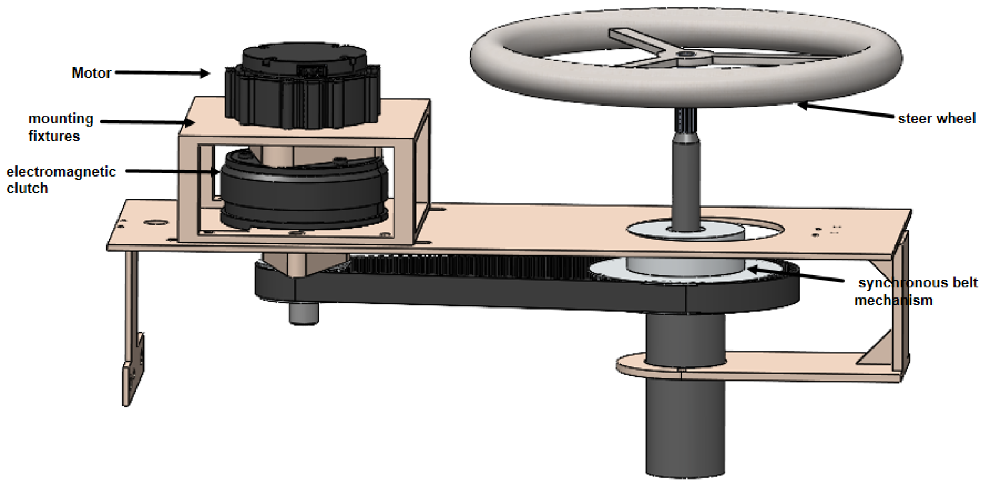
The autonomous steering function of unmanned ground vehicles can be achieved by integrating an automatic steering control device, which allows lateral control of the vehicle. Considering the structure of the vehicle’s steering system, it is feasible to position the steering control actuator on the steering shaft. Compared to selecting a motor with sufficiently large torque, choosing a motor combined with a reduction mechanism is a more cost-effective option. This not only increases the torque output of the mechanism but also enhances overall control precision. Dual-mode switching between autonomous and manual driving in unmanned ground vehicles can be achieved by employing an electromagnetic clutch to regulate the connection and disconnection between the motor and the steering shaft. Finally, the steering mechanism design consists of four components: the motor, the electromagnetic clutch, the synchronous belt mechanism, and the mounting fixtures, as shown in Figure 4.
Experimental results confirm that the steering wheel meets the expected performance criteria: the minimum time to achieve a full 360-degree turn is 0.82 s, and the controllable range for both clockwise and counterclockwise rotations exceeds 500 degrees.

2.1.2. Brake

As illustrated in Figure 5, the brake mechanism incorporates a DC motor that directly drives a ball screw, facilitating the movement of the worktable. The worktable is connected to a flexible shaft that drives the brake pedal. This design allows for precise control of the brake pedal state by adjusting the length of the flexible shaft’s movement. In addition, the motor controller disables the motor to allow manual braking. This braking solution is characterized by high precision and reliability, and its modular design facilitates easy assembly and maintenance.
Experimental measurements indicate that the response time of the brake pedal—from 0% to 100%—is less than 1 s, meeting the performance requirements specified by the autonomous driving system.

2.1.3. Accelerator

The electronic throttle serves as the primary actuation method in modern electric vehicles, wherein throttle modulation is achieved through sensor-based detection of pedal displacement. These sensor signals are transmitted to an electronic control unit (ECU), which interprets the input to modulate the electric motor’s output power in accordance with driver demand, thereby controlling vehicle velocity. In the proposed system, throttle control is achieved by configuring a microcontroller unit (MCU) to generate analog electronic throttle control signals corresponding to the desired throttle position. A relay-based switching mechanism is implemented to alternate between the MCU-generated control signal and the original electronic throttle input, enabling seamless transitions between manual and autonomous driving modes.

2.1.4. Gear Shift

In electric vehicles, gear shifting is typically implemented via a rotary switch that outputs a voltage signal corresponding to the selected gear, which is then transmitted to the vehicle’s control unit to determine and activate the appropriate drive mode. The mechanism underlying automatic gear control is analogous to that of electronic throttle regulation, involving a coordinated system of signal generation via a microcontroller unit (MCU) and relay-based actuation. However, unlike throttle control, the voltage levels required for gear selection exceed the direct output capability of the MCU. To address this limitation, a voltage relay module is integrated into the system to facilitate reliable control. The complete gear-shifting architecture comprises a dual-layer relay structure: the first layer is triggered by a mode selection switch to toggle between manual and autonomous driving modes, while the second layer is governed by the MCU to route the corresponding gear-selection voltage signal. This design ensures control system redundancy and enhances the adaptability and reliability of electric vehicles operating under multi-mode driving conditions.

2.1.5. Sensors

In addition to the actuators mentioned earlier, sensors that provide feedback on the vehicle’s posture are also essential. In the initial design of the perception system, the GPS module was considered as a component. However, due to the need to reduce overall system cost and the potential interference caused by unstable GPS signal strength in operational environments, GPS data was ultimately utilized solely for dataset construction and was not formally incorporated into the perception system. By utilizing point cloud data obtained through LiDAR scanning for relocalization within a known environment, the role of GPS in compensating for accumulated localization error within the positioning module is effectively replaced.
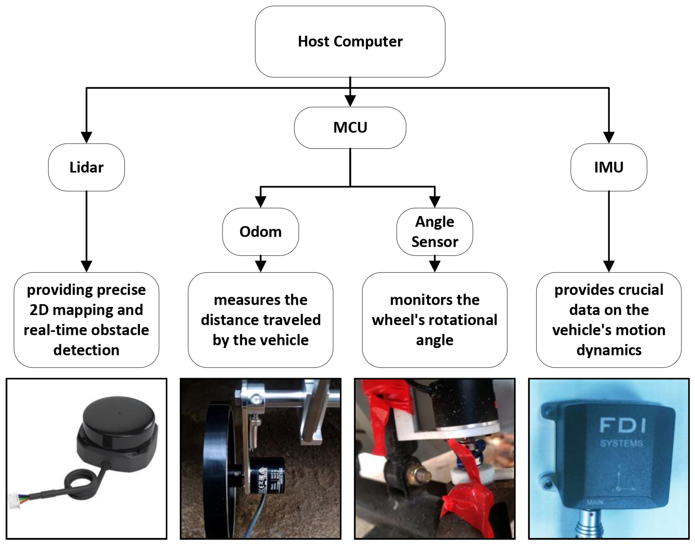
Given the exclusion of GPS, alternative sensors are deployed to support posture estimation and environmental perception. As illustrated in Figure 6, the sensor suite employed in this study comprises the RPLIDAR S2 laser scanner, the Epsilon_A inertial measurement unit (IMU), a single-turn absolute rotary encoder, and the E6B2-CWZ6C incremental encoder.
The LiDAR unit is mounted at the front of the vehicle and is responsible for acquiring two-dimensional environmental point cloud data, which is used to construct navigation maps and provide feedback for posture correction. The IMU features a six-axis configuration, integrating a tri-axial accelerometer and a tri-axial gyroscope with a sampling frequency of 1000 Hz. It measures the vehicle’s linear acceleration and angular velocity, and its data is fused with odometry inputs to enhance the accuracy of posture estimation. The rotary angle sensor offers a resolution of 10 bits and is connected to the front wheel steering shaft via a flexible rubber coupling to mitigate the effects of chassis vibration, enabling real-time acquisition of steering angle information. The E6B2-CWZ6C encoder is installed at the rear wheel axle and incorporates a spring-damping structure. With a resolution of 1000 pulses per revolution, it provides high-precision displacement and velocity feedback, supporting closed-loop regulation within the motion control module.
In the initial prototype vehicle, displacement estimation was derived from motor current readings rather than direct measurement via pulse encoders. This indirect approach resulted in limited odometric accuracy, which proved insufficient for maintaining stable posture feedback. To strike a balance between cost and precision, the system is subsequently equipped with an encoder mounted at the rear axle, serving as the primary odometry sensor for estimating vehicle displacement and posture variation. Mechanically coupled to the wheel shaft, the encoder features a spring-damping structure to mitigate vibration-induced interference, offering advantages in structural simplicity and cost-effectiveness. However, due to its exposed installation on the vehicle exterior, the sensor is susceptible to environmental factors such as dust, moisture, and mechanical impact, which may lead to signal fluctuations or hardware degradation—ultimately compromising the reliability and stability of posture estimation. To enhance long-term operational robustness, future iterations may consider adopting sealed, integrated wheel-speed sensors or incorporating alternative solutions such as visual odometry and inertial navigation systems, thereby improving posture feedback resilience under variable operating conditions.

2.2. Device Controller

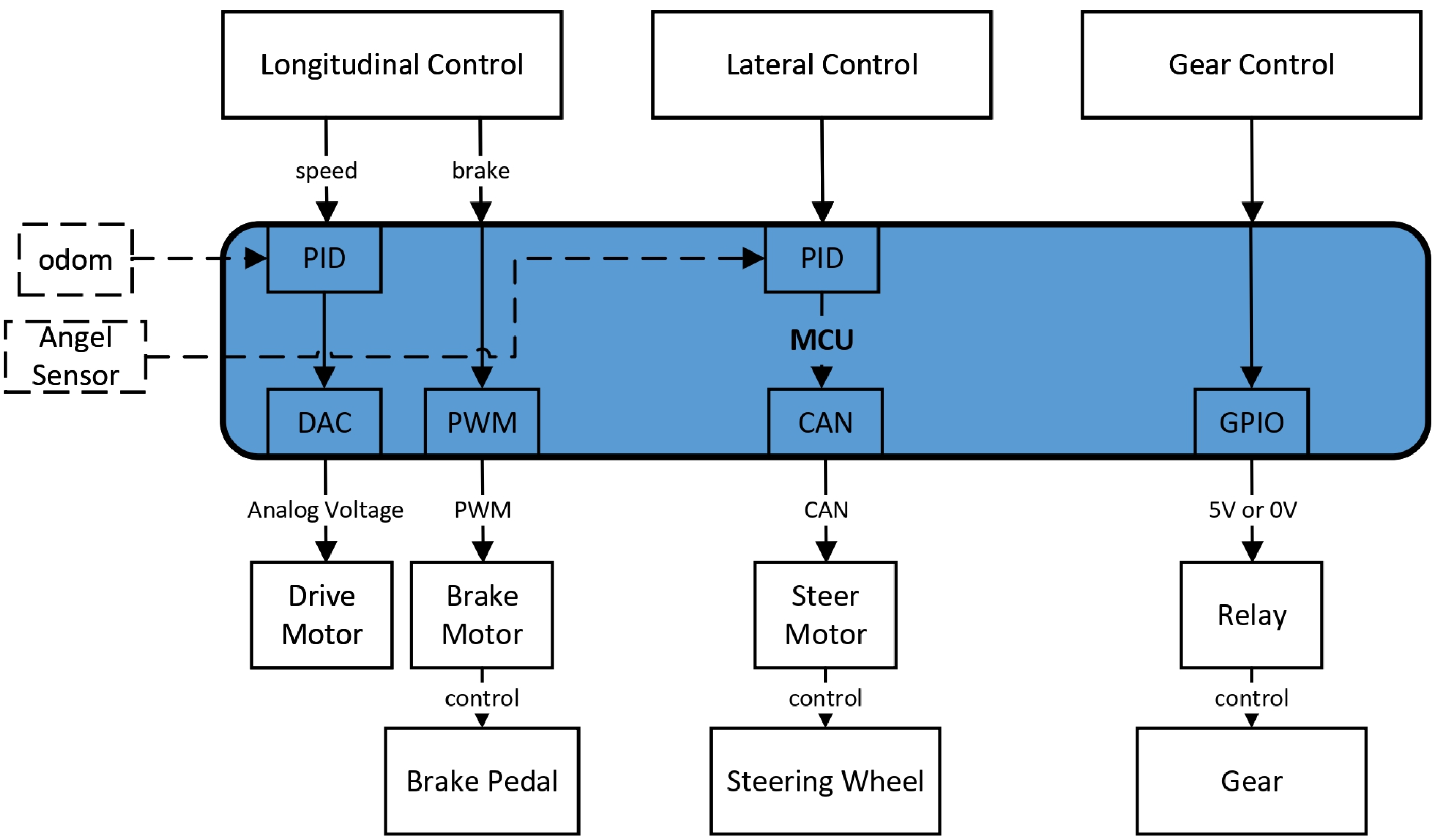
The device control module discussed in this chapter is deployed on the microcontroller unit. As illustrated in Figure 3, the controller is built on an STM32 development board based on the ARM architecture and operates under the FreeRTOS real-time operating system, enabling efficient actuator control and sensor data acquisition. Figure 7 illustrates how three categories of control commands are transmitted via the microcontroller unit to achieve precise actuation of the corresponding actuators.
Device control refers to the real-time control of the car base to meet the speed outputs of the planning server. In the design, the speed control commands v , w output by the planning server are used as inputs, where v represents the vehicle speed and w represents the angular velocity. These are then processed through vehicle kinematic calculations to obtain vehicle control commands v , δ f , where δ f is the steering angle of the front wheel. Finally, by leveraging the actuators, the control is divided into lateral and longitudinal control. The lateral and longitudinal controllers are designed based on their respective characteristics.

2.2.1. Lateral Control

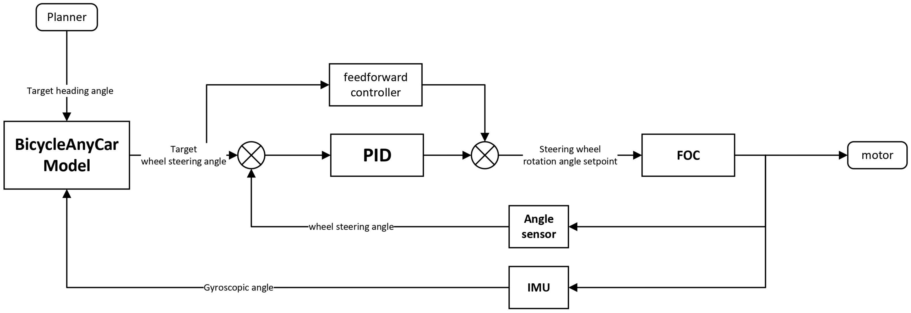
The actuator for the vehicle’s lateral control is the steering motor, which controls the steering wheel. The control target is the front wheel angle obtained from calculations. The motor control is achieved through closed-loop position FOC control, as illustrated in Figure 8.
However, the motor rotation control implemented through this method is influenced by factors such as friction within the steering mechanism and rotational clearance, which may lead to deviations between the actual control performance and the intended target. To address this, the angle sensor and the IMU are installed at the front wheel connection to provide feedback on the wheel steering angle and vehicle body attitude. Based on this feedback, a PID controller is designed to realize the lateral controller, as illustrated in Figure 9. In this system, the target heading angle generated by the path planner is transformed into the target front wheel steering angle through the vehicle dynamics model. Subsequently, the feedforward controller module is constructed based on the previously developed vehicle steering mechanism model and the modified timing belt transmission model, further integrated with experimental data to form an empirical model. This framework enables the generation of the desired control command for the steering motor. Finally, the real-time wheel steering angle obtained from the angle sensor is compared with the setpoint within a closed-loop PID control scheme, ensuring high-precision regulation of the steering angle.

2.2.2. Longitudinal Control

The drive motor of the electric vehicle serves as the direct actuator in longitudinal control. Due to incomplete characterization of its internal dynamics, a mapping between power, speed, and torque is not readily available [23,24]. Alternatively, the relationship between accelerator input u and vehicle speed v is measured and, analogous to the lateral control strategy outlined in Section 2.2.1, incorporated as a feed-forward component in the design of a PID controller, as illustrated in Figure 10.
In longitudinal control systems, in addition to accelerator regulation, it is also essential to design an effective braking control strategy. The braking subsystem adopted in this study utilizes a stepper motor to drive a leadscrew mechanism, which in turn actuates the movement of a work platform. Through a push-pull flexible shaft connected to the platform, the position of the brake pedal is adjusted to modulate braking force.

2.3. Device Planner

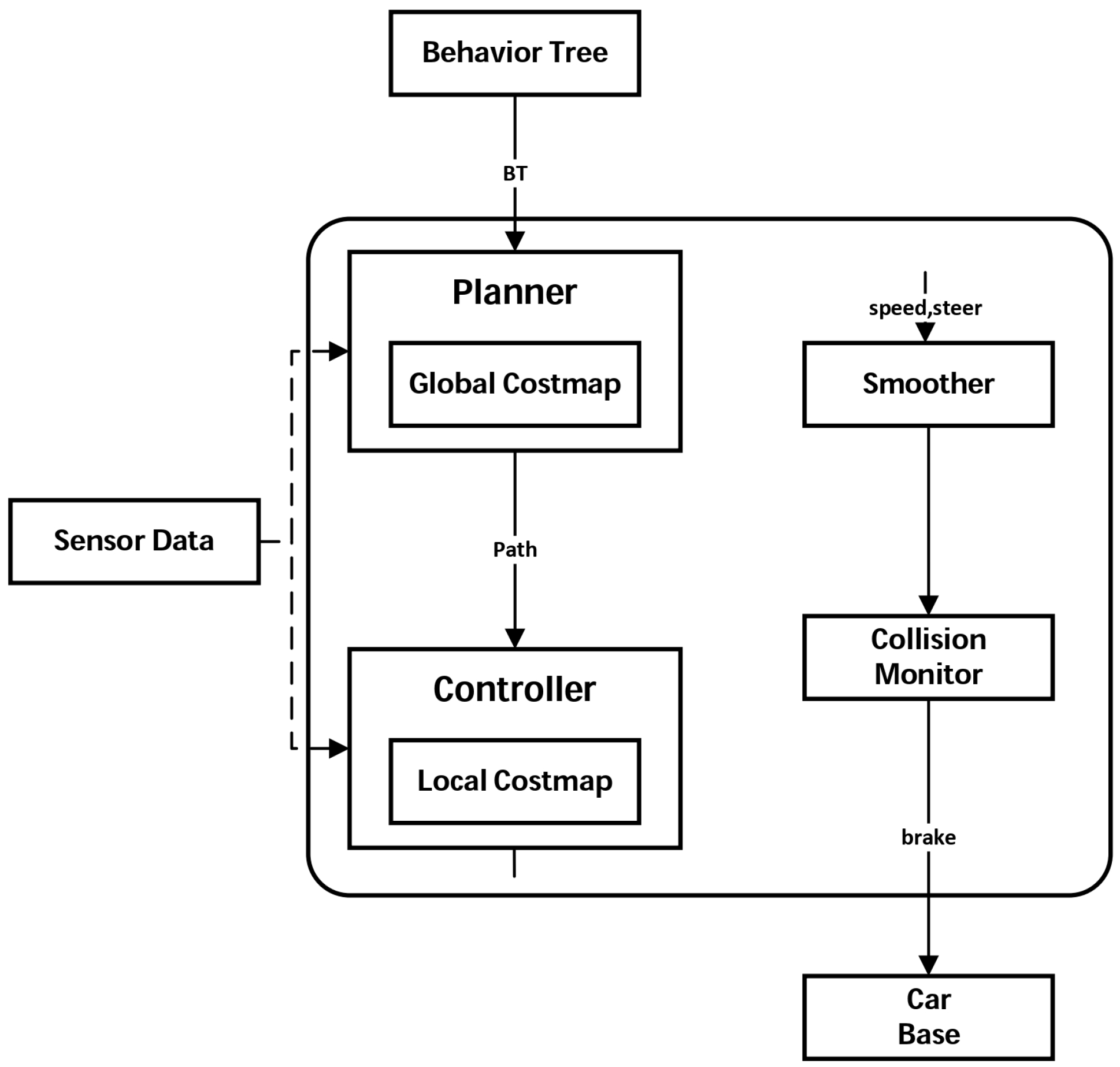
Figure 11 illustrates the system-level architecture of the device planner module, which serves as a foundational component within the autonomous navigation framework. The architecture adopts a hierarchical and modular design, enabling clear separation of functional responsibilities across planning, control, and safety layers. At the top level, a behavior tree governs task execution logic and delegates motion objectives to the planner. The planner integrates sensor inputs and global costmap data to generate feasible trajectories, which are subsequently transmitted to the controller for low-level command synthesis. The controller, informed by a local costmap, computes velocity and steering commands that are further refined by a smoothing module to ensure dynamic feasibility and comfort.
In parallel, a collision monitoring mechanism operates continuously to assess environmental risks and override control outputs when necessary, thereby enhancing system robustness. Final actuation commands are delivered to the vehicle base, which executes motion in accordance with both planned trajectories and safety constraints. This architecture underscores the planner’s role not only in trajectory generation but also in coordinating multi-layered control logic, laying the groundwork for the subsequent analysis of its design principles and operational performance.

2.3.1. Trajectory Plan

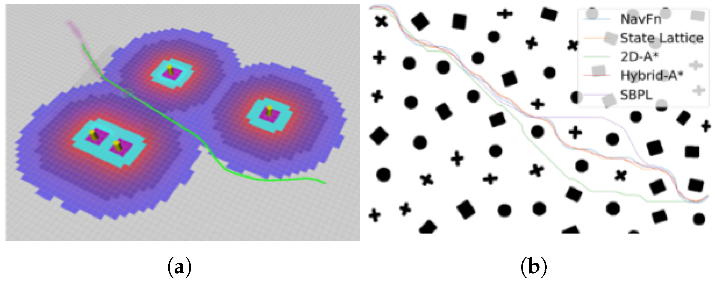
For trajectory planning in the proposed design, the Hybrid-A algorithm described in [25] is utilized. This method formulates the path planning problem as a search process within continuous space. In addition to expanding discrete grid nodes, it incorporates the vehicle’s motion model, thereby generating smoother and more feasible paths suitable for the bicycle model presented in Section 3.1. During node expansion, the Hybrid-A* algorithm accounts not only for adjacent grid locations but also generates a set of motion primitives derived from the motion model, facilitating optimal path discovery, as illustrated in Figure 12.
Unlike the traditional A* heuristic function, the Hybrid A* algorithm constructs two heuristic functions as described in [26]:
  • The first heuristic function is Constrained Heuristics, which considers only the vehicle’s non-holonomic constraints without considering obstacles. This heuristic ignores environmental obstacles and other information, focusing solely on the vehicle’s kinematic properties, and calculates the shortest path from the endpoint ( x g , y g , θ g ) = ( 0 , 0 , 0 ) to other points.
  • The second heuristic function is the dual of the first, called Unconstrained Heuristics, which considers only obstacle information without considering the vehicle’s non-holonomic constraints. It then applies the 2D dynamic programming method (essentially the traditional 2D A* algorithm) to calculate the shortest path from each node to the destination.
In addition, to address planning in narrow road conditions, a Voronoi potential field function is constructed. The value of the Voronoi field scales proportionally with the size of all feasible spaces in navigation. In the formula, d 0 and d V represent the distances from the path node to the nearest obstacle and the nearest Generalized Voronoi Diagram (GVD), respectively, while α > 0 controls the field’s falloff rate, as follows:
ρ V ( x , y ) = α α + d 0 ( x , y ) d v ( x , y ) d 0 ( x , y ) + d v ( x , y ) d 0 d m a x d m a x 2
Finally, the overall trajectory planning is accomplished through post-processing by optimizing an objective function composed of obstacle terms, curvature terms, smoothness terms, and Voronoi terms.

2.3.2. Trajectory Control

For trajectory control in the proposed design, the Model Predictive Path Integral (MPPI) algorithm described in [12] was selected. As a variant of Model Predictive Control (MPC), MPPI employs an iterative approach to compute control velocities. At each time step, the optimal control from the previous iteration and the current vehicle state are used to generate perturbations sampled from a Gaussian distribution. These stochastic inputs are forward-simulated to produce a set of candidate trajectories under the robot’s motion model. Each trajectory is evaluated using a collection of plug-in critic functions, and the best trajectory in the batch is identified. The corresponding scores are processed through a softmax function to derive the optimal control input. This procedure is repeated iteratively until convergence, with the resulting control serving as the initialization for subsequent time steps.
The overall flowchart is shown in Figure 13.
  • Trajectory generation is based on the current control sequence and the vehicle’s dynamic model, generating a series of possible trajectories through multiple simulations.
  • Cost calculation evaluates the performance of each generated trajectory using a cost function, considering factors such as target navigation and collision avoidance.
  • Path integration is a key concept of MPPI. It calculates the final control sequence via weighted averaging of all trajectories at each time step.
Figure 13. Procedural flowchart of the Model Predictive Path Integral (MPPI) control algorithm.
Energies 18 05247 g013
The core mechanism of MPPI, grounded in path integral theory and stochastic sampling, offers inherent advantages in handling complex dynamical systems. Unlike conventional optimization approaches such as Model Predictive Control (MPC), which rely on analytical gradients, MPPI maintains strong robustness and real-time responsiveness in high-dimensional, nonlinear settings—making it particularly well-suited for trajectory control tasks in autonomous driving applications. These advantages are especially pronounced in retrofitted autonomous platforms, which often face challenges such as heterogeneous sensor configurations, delayed controller responses, and constrained computational resources. MPPI’s distributed sampling strategy and tolerance to model inaccuracies enable stable performance under such conditions. Moreover, its support for parallel trajectory generation and evaluation aligns well with the limitations of embedded systems, enhancing control precision while meeting real-time operational requirements. As a result, MPPI demonstrates not only theoretical adaptability but also practical feasibility for deployment in retrofitted autonomous vehicle systems.
As discussed above, MPPI is able to comprehensively consider multiple possible future trajectories rather than relying on a single trajectory. MPPI generates the optimal trajectory by considering uncertainties and changes in a dynamic environment through multiple simulations and path integration. This makes MPPI suitable for mobile robots that require real-time planning, especially when facing dynamic environments and unknown obstacles.

2.3.3. Collision Monitor

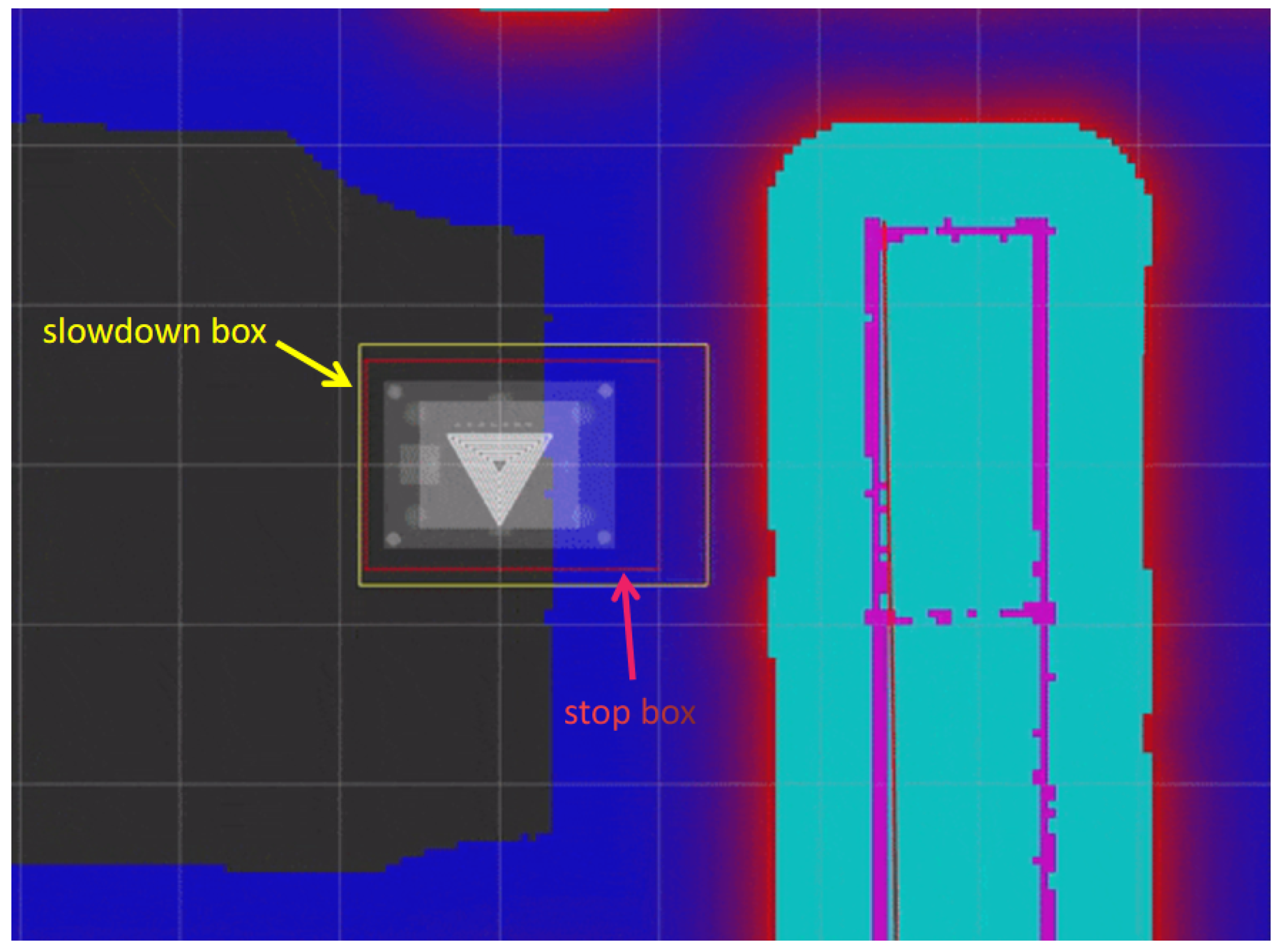
In addition to core navigation capabilities, a dedicated safety assurance module—referred to as the Collision Monitor—is implemented to prevent unintended collisions, such as those involving unexpected obstacles in rural environments (e.g., livestock). Operating independently of the navigation system, as depicted in the system architecture diagram in Section 2.3, the module is assigned the highest operational priority. It leverages lidar and ultrasonic sensors to detect proximal objects and administers deceleration and emergency braking maneuvers accordingly [27,28]. Within the planar navigation framework, the controlled entity is typically abstracted as a geometric primitive (e.g., rectangle or circle), represented by the white rectangle in Figure 14. To enhance safety, an auxiliary slowdown zone (yellow rectangular frame) and stop zone (red rectangular frame) are defined around the control object. Contact with an obstacle within these zones respectively triggers graduated deceleration or complete braking responses.

2.3.4. Localization

In the design, there are two localization schemes: one utilizes the Extended Kalman Filter (EKF) to fuse odom and IMU data for localization. During straight-line motion, the system prioritizes odometry data over integrated IMU measurements. Conversely, during rotation, it relies more on IMU data rather than the odom data calculated from ideal kinematics. However, over time, the cumulative localization error with this method increases [29,30]. Therefore, the Adaptive Monte Carlo Localization (AMCL) algorithm is also required for the relocalization function. AMCL is an algorithm used for localization. It estimates the car’s pose (position and orientation) using a particle filter method. AMCL leverages sensor data, such as from a LiDAR scanner, to match with a pre-constructed map, thereby determining the car’s precise location within the environment. The algorithm adapts to dynamically changing environments and continuously updates the car’s position estimate during navigation [31,32].

3. BicycleAnyCar Model

3.1. Bicycle Model

In the process from decision-making to planning and ultimately to control, the generation of a vehicle’s motion trajectory is indispensable. However, when evaluating the feasibility of curved trajectories, it becomes necessary to construct an appropriate vehicle motion model. Clearly, the more accurate the modeling, the smaller the error introduced during trajectory generation. Nonetheless, excessively complex models may compromise the generalizability of the system. Therefore, the bicycle model is commonly adopted due to its balance between simplicity and representational adequacy, as illustrated in Figure 15.
Consider the system input at time t to be (a, δ ), where a denotes the magnitude of acceleration in the direction of velocity. Assuming uniform linear motion occurs along this direction within the time interval d t , the following relationship can be established. The key parameters and notations used in the bicycle model for vehicle kinematics are summarized in Table 1.
x t + d t = x t + v t cos ( ψ t + β t ) d t
y t + d t = y t + v t sin ( ψ t + β t ) d t
v t + d t = v t + a · d t
ψ t + d t = ψ t + ω t · d t = ψ t + v t R t · d t
It can be derived through geometric principles that:
R t = l r sin β t
β t = tan 1 l r R ¯ t
R ¯ t = l r + l f tan δ
Table 1. Key Parameters and Notations in the Bicycle Model for Vehicle Kinematics.
SymbolicName/Unit
CThe rear axle center of the vehicle
l f Distance from C to the front axle center
l r Distance from C to the rear axle center
RTurning radius of C
R ¯ Turning radius of the rear axle center
ψ Yaw angle
δ Front wheel steering angle
β Sideslip angle
vVelocity of C
wAngular velocity of C about point O

3.2. Transformer Model

To address execution latency and load-induced dynamic perturbations encountered during control system deployment in retrofitted transport vehicles, this study leverages the transformer-based dynamics modeling framework released in [22]. Building upon this foundation, an adaptive control model is formulated for multi-platform scenarios characterized by high dynamic variability and hardware-induced uncertainties. The proposed framework incorporates a temporal attention mechanism to model state–action sequences, enabling accurate dynamic response prediction in the presence of significant state estimation errors and nonlinear physical disturbances. To enhance its applicability within retrofitted vehicle contexts, targeted modifications and extensions are introduced to both the architectural design and training pipeline of the original framework, thereby improving robustness, generalization capability, and control stability under real-world deployment constraints [33].
In addition, the stability and precision of vehicle control systems during real-world deployment are frequently challenged by external environmental factors. Variable payloads—such as differing weights of onboard equipment or passengers—can alter the vehicle’s dynamic response characteristics, thereby compromising the accuracy of trajectory tracking. Moreover, uneven terrain conditions, including muddy surfaces and gravel roads, may lead to tire slippage, induce attitude perturbations, and introduce significant sensor noise. These disturbances place increased demands on both state estimation algorithms and control strategies, necessitating enhanced robustness and adaptability to maintain reliable system performance under diverse operational scenarios.
To complement the proposed control framework and address the aforementioned deployment challenges, this study also establishes a tailored dataset construction pipeline, as illustrated in Figure 16. Built upon the multi-physics simulation infrastructure provided by the AnyCar system, the dataset integrates environments such as the Dynamic Bicycle Model (DBM), MuJoCo, Isaac Sim, and Assetto Corsa. On this foundation, a series of targeted augmentation strategies are introduced to emulate the operational characteristics of retrofitted transport vehicles:
  • Load Perturbation Modeling Mechanism: Multiple simulation scenarios featuring variable payload mass and distribution configurations are constructed to emulate the dynamic loading and unloading patterns observed in real-world freight operations. This augmentation enhances the model’s capability to perceive and represent the impact of load variations on vehicular dynamics.
  • Execution Latency Injection Strategy: Artificial disturbances—such as actuator response delays and servo control offsets—are introduced during simulated control processes to capture the non-ideal system behaviors commonly induced by retrofitted platforms. These perturbations reflect the influence of heterogeneous transmission systems and customized controller integration, thereby improving the realism and robustness of training data.
  • Environmental Heterogeneity Sampling Mechanism: Data acquisition scenarios are extended to encompass a range of terrain compositions (e.g., asphalt, soil) and traction load conditions, which enrich the diversity of the input state space. This design facilitates improved modeling of external environmental factors and their complex interactions with vehicle-level dynamics.
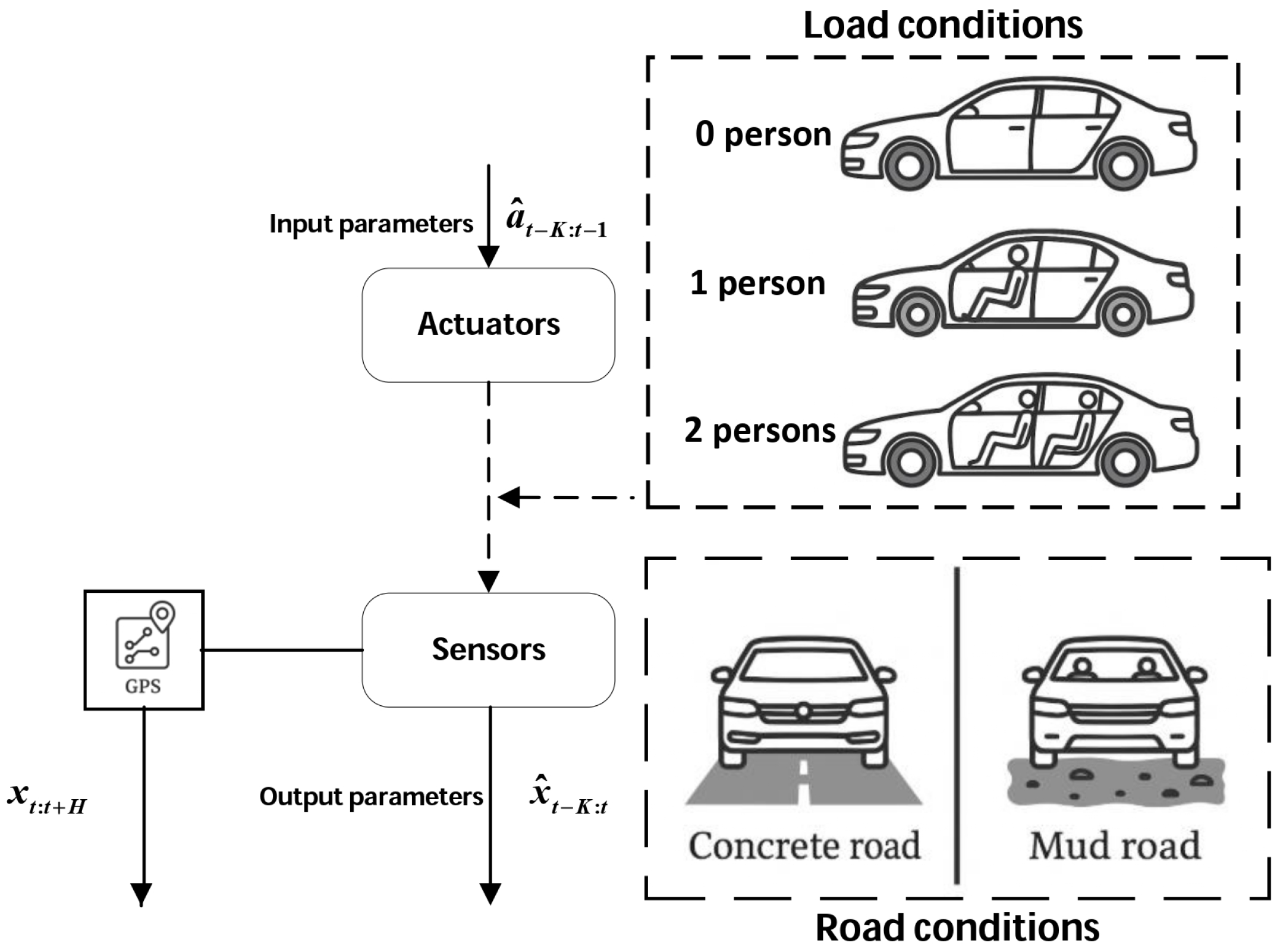
Figure 16. Workflow of dataset construction for autonomous driving model training.
Energies 18 05247 g016
In addition to the initial dataset comprising 100 M simulation samples and 0.02 M real-world samples, this study further collected approximately 4.1 h of driving data on the experimental platform—equivalent to roughly 0.728 M samples. The additional data spans a wide range of representative operating conditions and terrain types, aiming to enhance the model’s generalization capability and control stability under real-world deployment scenarios.
Building upon the transformer-based dynamics modeling framework proposed in [22], this study introduces a series of architectural and training-level enhancements tailored to the unique characteristics of retrofitted transport platforms. Such platforms often exhibit non-ideal behaviors—including actuator response delays, load-induced nonlinear dynamics, and sensor noise—that pose significant challenges to conventional control models. To address these issues, the transformer model is adapted to better capture temporal dependencies and improve robustness under uncertain operating conditions. Specifically, the model takes as input a sequence of historical states and planned actions, which are separately embedded into a 64-dimensional latent space. Temporal positional encoding is incorporated to preserve sequence structure, enabling the model to learn long-range correlations across time steps. The architecture comprises six stacked transformer layers, each consisting of multi-head self-attention mechanisms and feedforward networks. This design allows the model to selectively attend to critical segments of the input sequence—such as abrupt changes in vehicle dynamics or delayed control responses—that are particularly prevalent in retrofitted systems. In terms of training strategy, the model follows a two-stage learning pipeline as defined by the AnyCar framework. The first stage involves pretraining on approximately 100 million simulation steps sourced from diverse environments including MuJoCo, Isaac Sim, Assetto Corsa, and a dynamic bicycle model (DBM). These datasets are augmented with perturbations such as load variations, actuation delays, and terrain shifts to emulate real-world disturbances and enhance generalization. The second stage fine-tunes the pretrained model using a limited set of real-world trajectory data collected from the experimental retrofitted vehicle platform. This adaptation process calibrates the model to the physical characteristics and control response patterns of the target deployment system, thereby mitigating the sim-to-real distribution gap. To further reinforce model robustness, the training pipeline incorporates random masking and noise injection techniques. These strategies simulate sensor dropout and measurement errors, encouraging the model to infer missing or corrupted information through temporal context. Additionally, training is conducted under parameter stability constraints to prevent overfitting and ensure consistent performance across heterogeneous platforms.
Furthermore, this study introduces a hybrid modeling strategy that aims to integrate the temporal representation strength of transformer architectures with the physical interpretability of the bicycle kinematic model. While the transformer excels at capturing complex temporal dependencies from sequences of historical states and planned actions—making it well-suited for nonlinear and disturbance-prone control scenarios—the bicycle model offers a well-defined physical structure and dynamic constraints, contributing to stability and interpretability in trajectory prediction and control command generation.
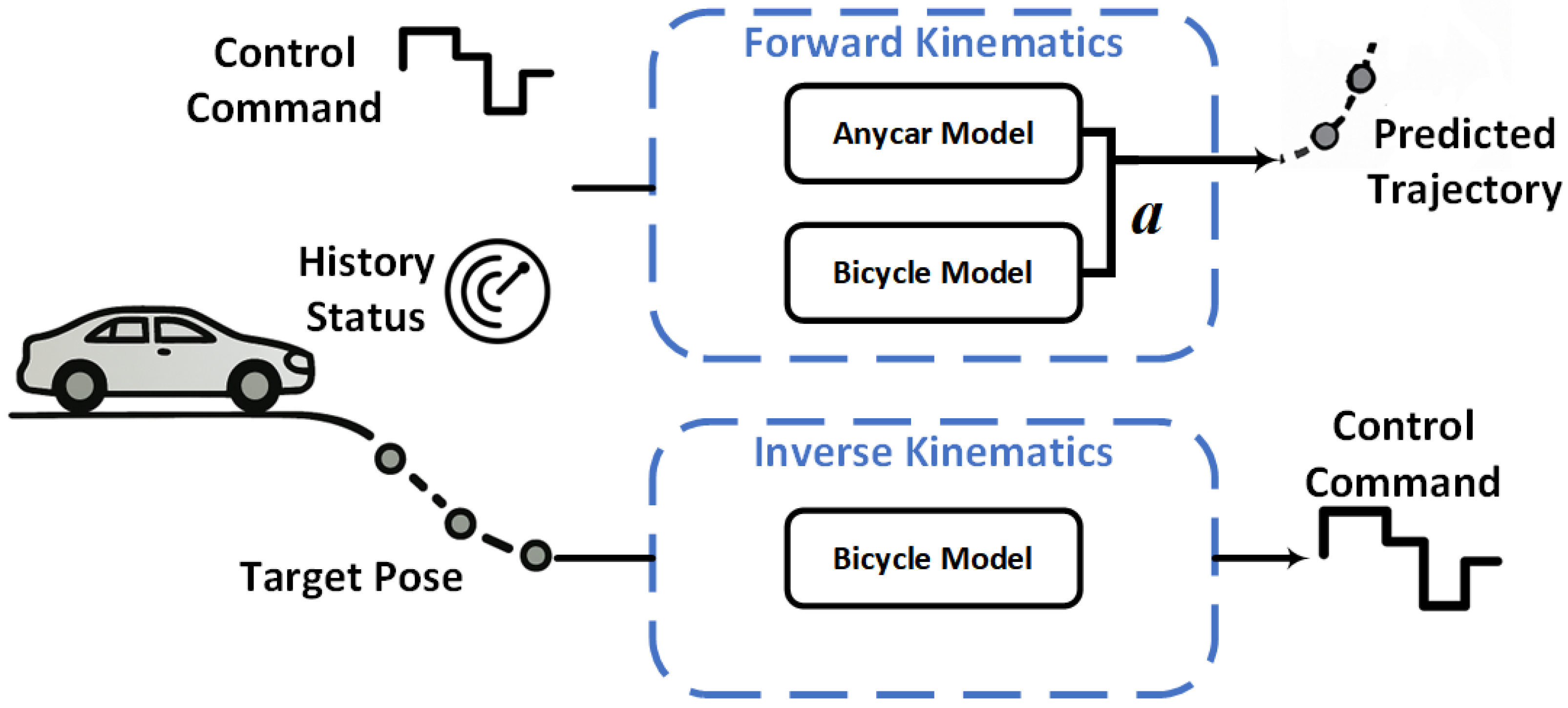
To leverage the complementary advantages of both models, a tunable fusion weighting parameter is designed to proportionally combine their respective outputs. This fusion mechanism supports weighted integration during trajectory estimation and allows dynamic adjustment during control command generation based on task-specific requirements. For instance, under high-speed driving or complex terrain conditions, the system can prioritize the physically grounded bicycle model to ensure stability. Conversely, in unstructured environments or scenarios with significant sensor noise, the transformer’s contribution can be amplified to enhance adaptability to environmental variations.
Specifically, let the output of the transformer model be denoted as x ^ T , the output of the bicycle model as x ^ B , and the fused result—used for final trajectory estimation or control command generation—as x ^ f u s e d . The fusion process can then be formulated as:
x ^ fused   = α · x ^ T + ( 1 α ) · x ^ B
here, α 0 , 1 denotes the fusion weighting parameter, representing the proportional contribution of the transformer model in the final fused output. This parameter can be dynamically configured by either the task scheduling module or the environmental perception module, depending on the current operational context.
  • Under conditions such as high-speed driving, sharp turns, or complex terrain, α is set to a lower range (e.g., 0.2–0.4), thereby emphasizing the physically grounded bicycle model to ensure trajectory stability and physical consistency.
  • In contrast, within unstructured environments, scenarios with significant sensor noise, or frequent dynamic disturbances, α is increased to a higher range (e.g., 0.6–0.8), allowing the transformer model to leverage its strengths in temporal representation and error tolerance.
The proposed fusion mechanism is primarily applied during the trajectory prediction phase, where the fused output x ^ f u s e d represents a sequence of predicted vehicle states over future time steps. These states typically include position coordinates (x, y), heading angle, linear velocity, and acceleration, and may also encompass additional dynamic variables such as wheel speed and yaw rate. The predictions are independently generated by the transformer-based temporal model and the map-based kinematic model, and subsequently integrated through a weighted combination governed by the fusion parameter α . This process yields the final trajectory estimation, as illustrated in the forward kinematics pipeline shown in Figure 17.
The proposed fusion strategy endows the system with the flexibility to seamlessly transition between different operational modes, thereby maintaining high levels of robustness and responsiveness across diverse and complex real-world scenarios. By incorporating a tunable model fusion mechanism into the control decision process, the system not only improves its tolerance to dynamic disturbances but also enhances its generalization capability in the face of platform heterogeneity and environmental uncertainty.

4. Results

The experiment was structured in two distinct phases: the first focused on the validation of the vehicle dynamic model, while the second aimed to evaluate the overall system’s navigation capabilities. During the vehicle model verification phase, the experiment was conducted on a closed test track, where the vehicle was manually driven along a predefined path. A comprehensive sensor suite was employed to continuously collect real-time motion data, which was then fed into various vehicle dynamic models to generate multiple trajectory outputs. Each resulting trajectory was analyzed and compared against GPS-recorded data to assess the accuracy and applicability of the respective models. In the system navigation evaluation phase, the closed test environment was utilized again, with multiple target endpoints defined. The vehicle was tasked with autonomously navigating to each endpoint. The performance of the system in these multi-goal navigation scenarios was examined to assess its path planning capabilities, environmental perception accuracy, and stability in posture estimation.

4.1. Overview of Experimental Platform and Testing Environment

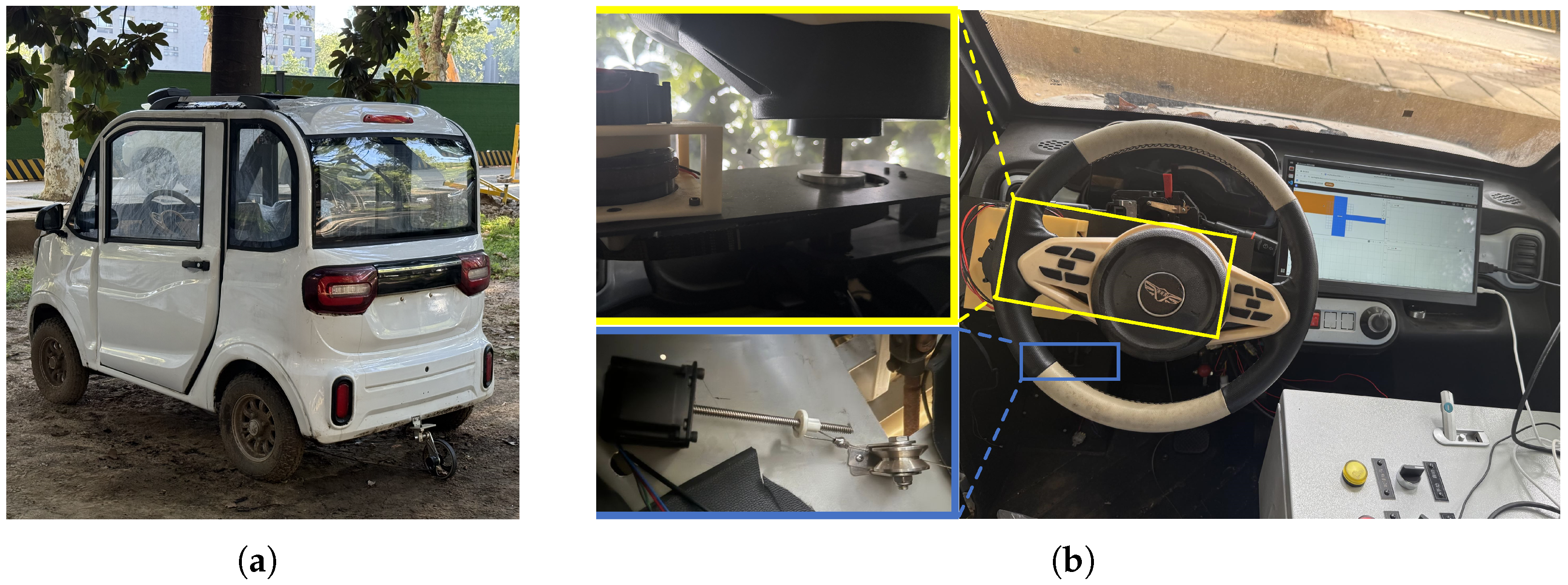
All experimental procedures in this study were conducted within a strictly controlled environment to ensure data acquisition consistency and minimize external disturbances that could affect system performance. The testing platform comprised a compact electric vehicle equipped with the aforementioned retrofitted actuator modules and a suite of heterogeneous sensors, supporting seamless transitions between manual and autonomous driving modes (see Figure 18).The corresponding hardware installation layout is illustrated in Figure 18b. The lidar and odometry wheels are mounted externally on the vehicle chassis, while the angle sensor is mechanically coupled to the front-wheel steering shaft via a flexible coupling. The steering actuator is rigidly affixed to the steering shaft, and the braking module is housed within the vehicle interior. All remaining electronic components are enclosed in an onboard control cabinet. To ensure signal integrity and operational reliability, shielded cables are employed throughout the wiring system, secured with locking clips to prevent displacement during motion. The mounting of all components has been engineered with sufficient structural robustness to accommodate vibrations and dynamic loads encountered during vehicle operation.
To evaluate the stability and generalization capability of the model under varying operational conditions, all testing tasks were conducted within a closed road environment, as illustrated in Figure 19a. Figure 19b further depicts the predefined driving route traversed by the vehicle within the test site, along which trajectory planning and control command validation were performed following the direction indicated by the arrows.

4.2. Vehicle Model Validation Test

In the validation experiments of the full-vehicle dynamic model, vehicle localization accuracy was selected as the primary evaluation metric to assess the effectiveness and stability of the model in spatiotemporal state estimation tasks. This metric reflects the model’s ability to reconstruct the spatial consistency of the vehicle’s actual trajectory, which is particularly critical for evaluating the integrated performance of the perception system and the vehicle-level solver following multi-source data fusion. Due to the suboptimal quality of GPS signals at the test site, high-precision localization data could not be reliably obtained. Consequently, GPS-based trajectory references were excluded from the evaluation process. As an alternative, the experiment employed a site-specific measurement strategy: the dimensions of the test track were manually surveyed, and the lane width was used as a tolerance threshold to assess the plausibility of predicted trajectories. Specifically, the experimental vehicle was manually driven along a predefined reference path within a closed test site to acquire ground-truth motion sensor data. The constructed dynamic model was subsequently used to infer vehicle positions step-by-step, generating predicted trajectories that were then aligned to and evaluated against the reference trajectory. To evaluate localization performance, the Trajectory Coverage Ratio (TCR) was calculated by measuring the proportion of predicted trajectory points falling within the effective experimental region. This metric quantitatively reflects the model’s spatial alignment accuracy and robustness under real-world operational conditions.
In the experimental section, this study employs three distinct trajectory estimation approaches to evaluate the effectiveness and performance of the proposed method:
  • First, a bicycle model is constructed based on the fusion of odometry (odom) data and wheel steering angle sensor inputs. The resulting trajectory is depicted as a green dashed line in Figure 20.
  • Second, building upon the aforementioned model, an Extended Kalman Filter is incorporated to integrate data from an IMU, thereby enhancing the system’s capability to perceive and estimate dynamic motion. This trajectory is illustrated as a red dashed line.
  • Finally, the method proposed in this paper further leverages a sequence learning model based on the transformer architecture, enabling deep modeling and synergistic inference of multi-source data. The resulting trajectory, represented by a blue solid line, demonstrates the significant advantages of the proposed approach in terms of both path accuracy and stability.
To further quantify the experimental results, the driving route was physically measured and designated as the reference trajectory. A positional error tolerance of less than 0.5 m was established. As illustrated in Figure 21, the yellow-shaded area denotes the experimental driving segment, while the blue-shaded area represents the designated parking region.
To assess the trajectory estimation performance of various models, the Trajectory Coverage Ratio (TCR) was adopted as the evaluation metric. In this experiment, TCR is defined as the proportion of estimated trajectory points that fall within the effective experimental region (i.e., the blue-shaded and yellow-shaded areas) relative to the total number of sampled points. This metric offers a direct measure of each model’s spatial alignment accuracy and its ability to maintain consistent coverage within the designated path boundaries.
To visually highlight the differences in trajectory estimation accuracy among the models, Table 2 summarizes the number of computed trajectory points falling within the experimental path region (indicated in yellow), the total number of sampled points, and the corresponding percentage-based Trajectory Coverage Ratio (TCR) values.
In real-world road scenarios, with a positional error tolerance set to 0.5 m, the proposed model achieved a Trajectory Coverage Ratio (TCR) of 94.8%, substantially outperforming the baseline model without the transformer module, which yielded a TCR of 54.6%. This result highlights the potential of the transformer architecture in capturing complex temporal patterns and effectively integrating multi-source data. Additionally, evaluation on the test set revealed that the proposed model achieved a Trajectory Coverage Ratio (TCR) of 72.3% under a stringent positional tolerance of 0.1 m, which increased to 97.5% when the tolerance was relaxed to 0.5 m. These results underscore the model’s robustness and adaptability across varying precision thresholds. Furthermore, the Etracking assessment yielded a score of 0.61 ± 0.05, providing additional evidence of the model’s temporal consistency and spatial alignment in dynamic scenarios.

4.3. Autonomous Navigation System Evaluation

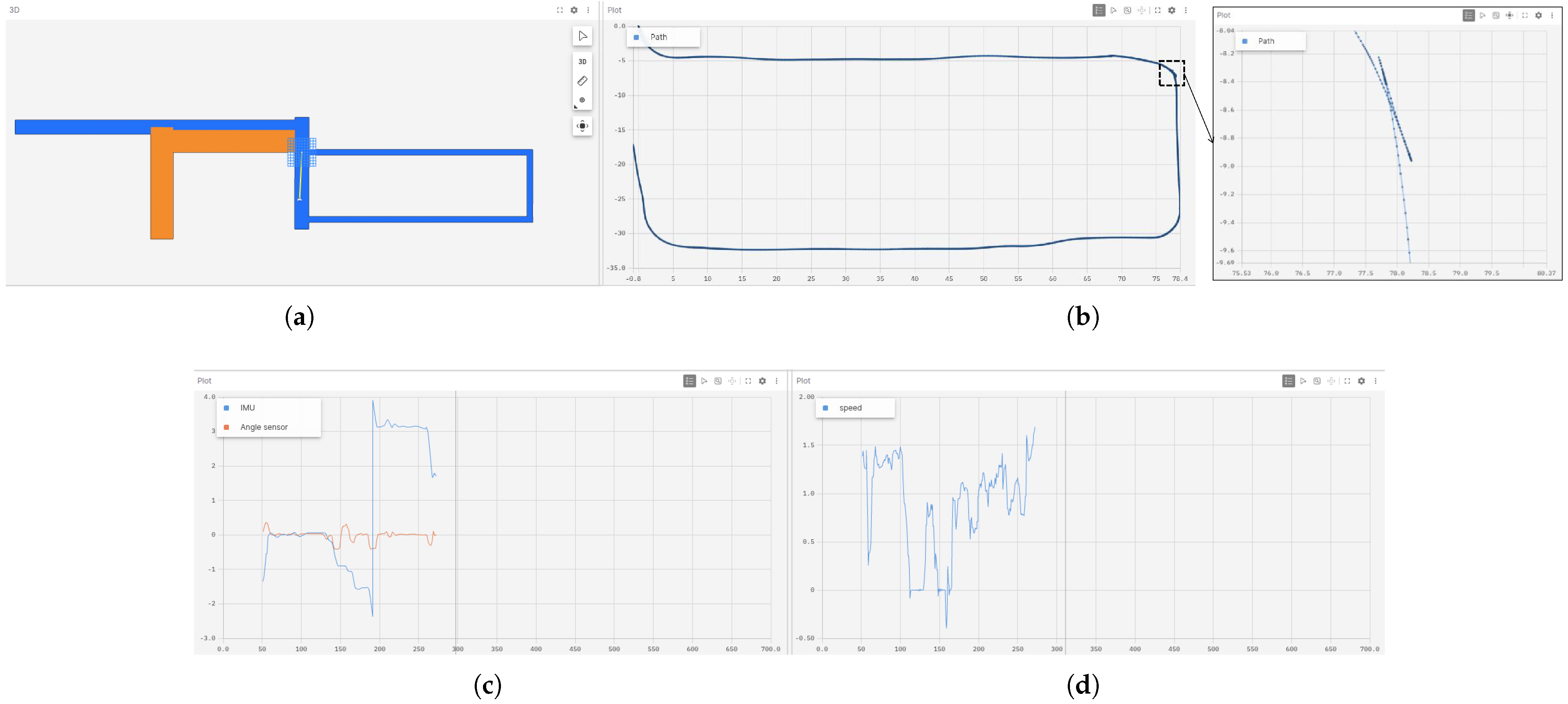
In the performance evaluation experiment of the autonomous navigation system evaluation, the test route was selected as the rectangular section of the roadway described in Section 4.1. Navigation testing was conducted based on a predefined set of target destinations. All obstacles present in the test environment were static, including roadside objects and predefined boundary constraints, ensuring consistent interaction conditions throughout the experiment. During experimentation, the Foxglove platform was utilized to develop an integrated visualization interface, thereby improving the clarity of data presentation and enhancing the intuitiveness of system-level interaction (as illustrated in Figure 22).
To systematically evaluate the performance of both longitudinal and lateral vehicle control, Figure 23 provides a comparative visualization of control commands and corresponding feedback signals. Figure 23a illustrates the velocity command output generated by the speed control module (blue dashed line), along with the measured velocity feedback (red solid line), reflecting the dynamic response of the closed-loop control system. Additionally, the figure includes the throttle input control signal (green dashed line), represented as an analog signal used to actuate the powertrain, whose variation further reveals the coupling characteristics between control commands and actuator behavior. Figure 23b depicts the yaw-axis control signal derived from angular velocity commands issued by the navigation system (blue dashed line), together with real-time yaw angle feedback (red solid line) obtained from the IMU sensor, validating the system’s precision and stability in directional control. The figure also presents the average front-wheel steering angle (gray solid line), which characterizes the vehicle’s actual steering response and supports the analysis of the lateral control strategy’s adaptability and execution consistency under varying operational conditions.
The final testing phase of the navigation system was successfully completed, with no collisions occurring throughout the experiment, thereby confirming the system’s safety under static obstacle conditions. However, a single instance of manual intervention was required, suggesting that the system still has room for localized optimization when managing complex scenarios. The total duration of the test was approximately 370 s, representing a 58.2% increase compared to the manual driving benchmark conducted in the initial phase. Upon analysis, the observed performance gap can be primarily attributed to two factors. First, the path planning module adopts a conservative strategy when handling dynamic obstacles and safety boundaries, which results in reduced overall driving speed. Second, the retrofitted platform exhibits execution latency, including delayed controller responses and asynchronous sensor data fusion—issues that become particularly pronounced under complex terrain and varying load conditions. These factors collectively constrain the system’s operational efficiency, indicating that the current approach still requires further optimization in terms of real-time responsiveness and execution performance. Although the system exhibited a 58.2% increase in average travel time compared to human drivers during field deployment, this performance gap is offset by its ability to operate continuously without the need for rest. Such endurance offers a distinct advantage in long-duration, high-frequency transport tasks. In particular, the system demonstrates strong potential in repetitive and route-fixed scenarios such as farm logistics and mining material transfer, where it can maintain stable, round-the-clock operation. This capability not only reduces labor dependency but also enhances overall operational efficiency, underscoring the system’s applicability and value in low-risk autonomous transport environments.

5. Conclusions

This study proposes an economical, environmentally friendly, and modular unmanned ground vehicle (UGV) system equipped with both autonomous and manual driving modes. Designed to perform cargo pickup, transport, and delivery tasks, the system is tailored for heavy-duty operations in low-risk environments such as farms, mining areas, and industrial parks.
To meet application-specific requirements, the UGV was retrofitted from a conventional electric vehicle platform through a systematic automation upgrade. The implementation integrates a full suite of actuation mechanisms, including electronically controlled steering systems, electric braking modules, and drivetrain controllers. Additionally, key perception sensors—such as LiDAR and an inertial measurement unit (IMU)—were incorporated to support accurate navigation and situational awareness, laying the groundwork for trajectory planning and control algorithm deployment.
Considering the response delays and actuation lag stemming from retrofitted control architecture, this work further introduces a simplified vehicle dynamics framework based on the Bicycle Model. It is augmented with a transformer-based deep learning architecture to enhance modeling fidelity and control generalization on non-standard platforms. Leveraging a customized dataset for training and optimization, the proposed model demonstrates improved adaptability to complex operational scenarios while providing a methodological basis for efficient energy use and safety-focused control.
In real-world road experiments with a positional tolerance threshold set to 0.5 m, the transformer-enhanced trajectory estimation method achieved an accuracy of 94.8%, substantially outperforming the non-transformer model (54.6%). These outcomes validate the model’s precision and robustness under real-world operational conditions.
Furthermore, the navigation system test was successfully conducted in a closed-road environment with zero collision incidents and only one instance of manual intervention. The total operation duration was approximately 370 s—58.2% longer than the manually driven benchmark—highlighting basic operational stability while revealing areas for performance optimization.
In summary, the key contributions of this work are summarized as follows:
  • A modular unmanned ground vehicle (UGV) system is developed for low-risk environments, featuring dual-mode autonomous and manual control. The system offers high deployment flexibility and cost-efficiency, making it suitable for open-field scenarios such as farms and mining sites, in contrast to conventional high-cost, fully integrated autonomous platforms.
  • A distributed algorithmic framework is proposed for low-cost platforms, comprising lateral and longitudinal PID controllers deployed on microcontrollers, and a hybrid A* global planner with an MPPI-based local trajectory optimizer running on the host computing unit. This architecture enables effective coordination between planning and control under resource-constrained hardware conditions, enhancing both system stability and deployment scalability.
  • Building upon the AnyCar architecture and leveraging a custom dataset and experimental platform, this study designs and optimizes a vehicle dynamics modeling approach—termed the BicycleAnyCar Model. By integrating the classical bicycle kinematic model with deep temporal modeling capabilities, the proposed method effectively captures nonlinear dynamic behaviors inherent to retrofitted platforms. Experimental results demonstrate that it significantly outperforms conventional models in both trajectory estimation accuracy and control stability.
  • The system’s trajectory tracking performance and control resilience are validated on a retrofitted platform under real-world disturbances such as actuation delay, demonstrating strong engineering adaptability and scalability.
The following directions outline our intended efforts to further improve system performance and applicability:
  • Currently, the transformer model is deployed on a remote 3090 GPU server. Although single-pass inference latency is maintained within 0.05 s, the overall responsiveness in navigation tasks is still challenged by network-induced delays, which may interfere with time-sensitive control cycles. To improve system real-time capability and robustness, a local inference acceleration strategy is proposed—compressing segments of the transformer model and deploying them on edge devices or onboard platforms, combined with low-latency inference engines to reduce dependence on remote communication channels.
  • During navigation experiments, sporadic failures have been observed in vehicle posture adjustment or the execution of low-level control commands, leading to situations where the navigation module is unable to resolve a feasible trajectory, thus causing the vehicle to enter a stalled state. To address this, a recovery mechanism with redundant control logic is recommended. This mechanism would activate emergency routines—such as trajectory backtracking and autonomous posture correction—when navigation failure or control deviation is detected, thereby enhancing system recoverability and continuity under dynamically changing operational conditions.
  • Under future research directions, continued refinement of the proposed methodology will focus on developing more efficient and generalizable modeling and control strategies to improve system robustness and responsiveness in complex environments. In addition, systematic benchmarking against mainstream machine learning architectures—such as LSTM, GRU, and GNN—will be conducted to comprehensively evaluate the performance and cross-domain applicability of the approach.
  • To align with the broader analytical focus on power consumption and cost-effective transportation, an integrated energy monitoring mechanism will be introduced in subsequent development stages, enabling systematic evaluation of control strategies in terms of energy efficiency and operational economy.

Author Contributions

Conceptualization, K.W. and K.-M.M.; methodology, K.W.; software, X.Z. and C.-C.Z.; validation, X.Z., Z.-J.P., and J.-J.T.; formal analysis, K.W. and Z.-J.P.; investigation, C.-C.Z. and Z.-J.P.; resources, X.Z.; data curation, K.W. and Z.-J.P.; writing—original draft preparation, K.W.; writing—review and editing, K.W. and K.-M.M.; visualization, K.W., X.Z., and C.-C.Z.; supervision, X.Z. and J.-J.T.; project administration, K.-M.M.; funding acquisition, K.-M.M. All authors have read and agreed to the published version of the manuscript.

Funding

The work was supported by the National Key Research and Development Program of Ningxia Province [grant number: 2021BFH02001].

Data Availability Statement

The original contributions presented in the study are included in the article; further inquiries can be directed to the corresponding author.

Conflicts of Interest

The authors declare no conflicts of interest.

References

  1. Abdel-Aty, M.; Ding, S. A matched case-control analysis of autonomous vs human-driven vehicle accidents. Nat. Commun. 2024, 15, 4931. [Google Scholar] [CrossRef] [PubMed]
  2. Liu, H.X.; Feng, S. Curse of rarity for autonomous vehicles. Nat. Commun. 2024, 15, 4808. [Google Scholar] [CrossRef] [PubMed]
  3. Zhang, L.; Zhao, J.; Long, P.; Wang, L.; Qian, L.; Lu, F.; Song, X.; Manocha, D. An autonomous excavator system for material loading tasks. Sci. Robot. 2021, 6, eabc3164. [Google Scholar] [CrossRef] [PubMed]
  4. Kato, S.; Takeuchi, E.; Ishiguro, Y.; Ninomiya, Y.; Takeda, K.; Hamada, T. An open approach to autonomous vehicles. IEEE Micro 2015, 35, 60–68. [Google Scholar] [CrossRef]
  5. Tang, J.; Wang, J.; Ji, K.; Xu, L.; Yu, J.; Shi, Y. A Unified Diffusion Framework for Scene-Aware Human Motion Estimation from Sparse Signals. In Proceedings of the IEEE/CVF Conference on Computer Vision and Pattern Recognition (CVPR), IEEE/CVF, Seattle, WA, USA, 17–21 June 2024; pp. 21251–21262. [Google Scholar]
  6. Sun, W.; Chen, Z.; Wang, Y.; Li, J. SparseDrive: End-to-End Autonomous Driving via Sparse Scene Representation. In Proceedings of the 2025 IEEE International Conference on Robotics and Automation (ICRA), IEEE, Atlanta, GA, USA, 19–23 May 2025. [Google Scholar]
  7. Jiang, B.; Chen, S.; Xu, Q.; Liao, B.; Chen, J.; Zhou, H.; Zhang, Q.; Liu, W.; Huang, C.; Wang, X. VAD: Vectorized Scene Representation for Efficient Autonomous Driving. In Proceedings of the IEEE/CVF International Conference on Computer Vision (ICCV), IEEE/CVF, Paris, France, 2–6 October 2023; pp. 8340–8350. [Google Scholar]
  8. Zhao, G.; Chen, Z.; Liao, W. Reinforcement-tracking: An end-to-end trajectory tracking method based on self-attention mechanism. Int. J. Automot. Technol. 2024, 25, 541–551. [Google Scholar] [CrossRef]
  9. Song, Z.; Jia, C.; Liu, L.; Pan, H.; Zhang, Y.; Wang, J.; Zhang, X.; Xu, S.; Yang, L.; Luo, Y. Don’t Shake the Wheel: Momentum-Aware Planning in End-to-End Autonomous Driving. In Proceedings of the IEEE/CVF Conference on Computer Vision and Pattern Recognition (CVPR), IEEE/CVF, Nashville, TN, USA, 11–15 June 2025; pp. 22432–22441. [Google Scholar]
  10. Williams, G.; Drews, P.; Goldfain, B.; Rehg, J.M.; Theodorou, E.A. Aggressive Driving with Model Predictive Path Integral Control. In Proceedings of the 2016 IEEE International Conference on Robotics and Automation (ICRA), IEEE, Stockholm, Sweden, 16–21 May 2016; pp. 1433–1440. [Google Scholar]
  11. Yin, J.; Zhang, Z.; Theodorou, E.; Tsiotras, P. Trajectory Distribution Control for Model Predictive Path Integral Control Using Covariance Steering. In Proceedings of the 2022 IEEE International Conference on Robotics and Automation (ICRA), IEEE, Philadelphia, PA, USA, 23–27 May 2022; pp. 1478–1484. [Google Scholar]
  12. Li, Y.; Zhu, Q.; Elahi, A. Quadcopter trajectory tracking based on model predictive path integral control and neural network. Drones 2024, 9, 9. [Google Scholar] [CrossRef]
  13. Viadero-Monasterio, F.; Meléndez-Useros, M.; Zhang, N.; Zhang, H.; Boada, B.L.; Boada, M.J.L. Motion Planning and Robust Output-Feedback Trajectory Tracking Control for Multiple Intelligent and Connected Vehicles in Unsignalized Intersections. IEEE Trans. Veh. Technol. 2025. [Google Scholar] [CrossRef]
  14. Zheng, J.; Chen, T.; He, J.; Wang, Z.; Gao, B. Review on Security Range Perception Methods and Path-Planning Techniques for Substation Mobile Robots. Energies 2024, 17, 4106. [Google Scholar] [CrossRef]
  15. Xia, X.; Hashemi, E.; Xiong, L.; Khajepour, A. Autonomous vehicle kinematics and dynamics synthesis for sideslip angle estimation based on consensus Kalman filter. IEEE Trans. Control Syst. Technol. 2022, 31, 179–192. [Google Scholar] [CrossRef]
  16. Chen, T.; Cai, Y.; Chen, L.; Xu, X. Sideslip angle fusion estimation method of three-axis autonomous vehicle based on composite model and adaptive cubature Kalman filter. IEEE Trans. Transp. Electrif. 2023, 10, 316–330. [Google Scholar] [CrossRef]
  17. Chen, Y.; Liu, F.; Pei, K. Cross-modal matching cnn for autonomous driving sensor data monitoring. In Proceedings of the IEEE/CVF International Conference on Computer Vision, IEEE, Montreal, QC, Canada, 11–17 October 2021; pp. 3110–3119. [Google Scholar]
  18. Duan, J.; Guan, Y.; Li, S.E.; Ren, Y.; Sun, Q.; Cheng, B. Distributional soft actor-critic: Off-policy reinforcement learning for addressing value estimation errors. IEEE Trans. Neural Netw. Learn. Syst. 2021, 33, 6584–6598. [Google Scholar] [CrossRef] [PubMed]
  19. Amin, F.; Gharami, K.; Sen, B. TrajectoFormer: Transformer-based trajectory prediction of autonomous vehicles with spatio-temporal neighborhood considerations. Int. J. Comput. Intell. Syst. 2024, 17, 87. [Google Scholar] [CrossRef]
  20. Kotb, M.; Weber, C.; Hafez, M.B.; Wermter, S. QT-TDM: Planning with transformer dynamics model and autoregressive q-learning. IEEE Robot. Autom. Lett. 2024, 10, 112–119. [Google Scholar] [CrossRef]
  21. Yu, C.; Yang, Y.; Liu, T.; You, Y.; Zhou, M.; Xiang, D. State Estimation Transformers for Agile Legged Locomotion. In Proceedings of the 2024 IEEE/RSJ International Conference on Intelligent Robots and Systems (IROS), IEEE, Abu Dhabi, United Arab Emirates, 14–18 October 2024; pp. 6810–6817. [Google Scholar]
  22. Xiao, W.; Xue, H.; Tao, T.; Kalaria, D.; Dolan, J.M.; Shi, G. Anycar to Anywhere: Learning Universal Dynamics Model for Agile and Adaptive Mobility. In Proceedings of the 2025 IEEE International Conference on Robotics and Automation (ICRA), IEEE, Atlanta, GA, USA, 19–23 May 2025. [Google Scholar]
  23. Zhou, Y.; Liu, C.; Li, Z.; Yu, Y. A Model Predictive Control Strategy with Minimum Model Error Kalman Filter Observer for HMEV-AS. Energies 2025, 18, 1557. [Google Scholar] [CrossRef]
  24. Pires, T.R.; Fernandes, J.F.; Branco, P.J.C. Driving Profile Optimization for Energy Management in the Formula Student Técnico Prototype. Energies 2024, 17, 6313. [Google Scholar] [CrossRef]
  25. Kurzer, K. Path Planning in Unstructured Environments: A Real-time Hybrid A* Implementation for Fast and Deterministic Path Generation for the KTH Research Concept Vehicle. Master’s Thesis, KTH Royal Institute of Technology, Stockholm, Sweden, 2016. [Google Scholar]
  26. Dolgov, D.; Thrun, S.; Montemerlo, M.; Diebel, J. Practical Search Techniques in Path Planning for Autonomous Driving. In Proceedings of the AAAI 2008 Spring Symposium, Stanford University, Palo Alto, CA, USA, 26–28 March 2008; pp. 18–80. [Google Scholar]
  27. Yin, Y.; Wang, Z.; Zheng, L.; Su, Q.; Guo, Y. Autonomous UAV navigation with adaptive control based on deep reinforcement learning. Electronics 2024, 13, 2432. [Google Scholar] [CrossRef]
  28. Xi, M.; Dai, H.; He, J.; Li, W.; Wen, J.; Xiao, S.; Yang, J. A lightweight reinforcement-learning-based real-time path-planning method for unmanned aerial vehicles. IEEE Internet Things J. 2024, 11, 21061–21071. [Google Scholar] [CrossRef]
  29. Alatise, M.B.; Hancke, G.P. A review on challenges of autonomous mobile robot and sensor fusion methods. IEEE Access 2020, 8, 39830–39846. [Google Scholar] [CrossRef]
  30. Huang, Y.; Zhang, Y.; Xu, B.; Wu, Z.; Chambers, J.A. A new adaptive extended Kalman filter for cooperative localization. IEEE Trans. Aerosp. Electron. Syst. 2017, 54, 353–368. [Google Scholar] [CrossRef]
  31. Gupta, A.; Fernando, X. Simultaneous localization and mapping (slam) and data fusion in unmanned aerial vehicles: Recent advances and challenges. Drones 2022, 6, 85. [Google Scholar] [CrossRef]
  32. Wang, S.; Ahmad, N.S. A Comprehensive Review on Sensor Fusion Techniques for Localization of a Dynamic Target in GPS-Denied Environments. IEEE Access 2024, 13, 2252–2285. [Google Scholar] [CrossRef]
  33. Celestini, D.; Gammelli, D.; Guffanti, T.; D’Amico, S.; Capello, E.; Pavone, M. Transformer-based model predictive control: Trajectory optimization via sequence modeling. IEEE Robot. Autom. Lett. 2024, 9, 9820–9827. [Google Scholar] [CrossRef]
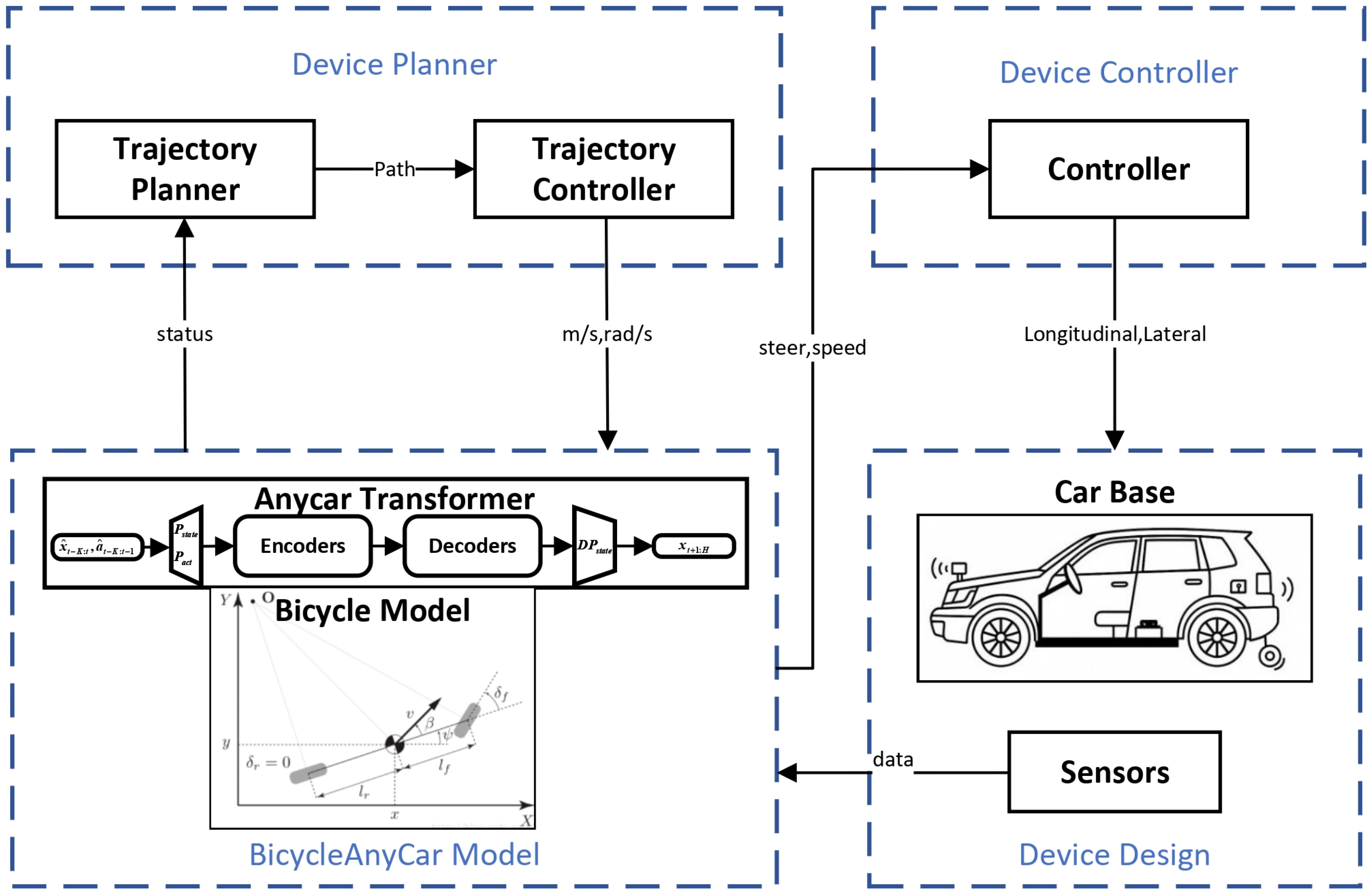
Figure 1. Functionalblock diagram of the complete autonomous driving system architecture.
Energies 18 05247 g001
Figure 2. Overall design diagram of autonomous vehicles.
Energies 18 05247 g002
Figure 3. Hardware architecture overview of the autonomous driving platform.
Energies 18 05247 g003
Figure 4. Detailed design of the steering mechanism for autonomous vehicle control.
Energies 18 05247 g004
Figure 5. Structural design of the braking mechanism for autonomous vehicle control.
Energies 18 05247 g005
Figure 6. Functional architecture of the sensor subsystem in autonomous driving.
Energies 18 05247 g006
Figure 7. MCU system architecture for real-time vehicle control.
Energies 18 05247 g007
Figure 8. Field-oriented control (FOC) model for precision motor actuation. (Note: S denotes speed estimation).
Energies 18 05247 g008
Figure 9. Control architecture of the lateral motion control module.
Energies 18 05247 g009
Figure 10. Control architecture of the longitudinal motion control module.
Energies 18 05247 g010
Figure 11. System architecture of the vehicle-level device planner module.
Energies 18 05247 g011
Figure 12. Output trajectories generated by the Hybrid-A path planning algorithm: (a) Performance visualization of the hybrid-A algorithm. (b) Comparative analysis of various path planning algorithms.
Energies 18 05247 g012
Figure 14. Collision monitoring results under simulated driving scenarios.
Energies 18 05247 g014
Figure 15. Schematic representation of the bicycle kinematic model for vehicle motion analysis.
Energies 18 05247 g015
Figure 17. Architecture of the proposed BicycleAnyCar Model.
Energies 18 05247 g017
Figure 18. Retrofitted electric vehicle used for experimental testing: (a) External configuration of the experimental vehicle. (b) Internal configuration of the experimental vehicle.
Energies 18 05247 g018
Figure 19. Layout of the enclosed test track used in experimental validation: (a) closed road environment for model robustness evaluation. The illustrated route was generated using a mobile navigation application and may exhibit minor discrepancies compared to the actual road layout. In the real-world testing environment, the road structure is more regular and approximately rectangular in shape, which facilitates reliable validation of trajectory planning and control algorithms. (b) Predefined Driving Route for Trajectory Planning and Control Validation.
Energies 18 05247 g019
Figure 20. Comparative trajectory estimation via multi-modal sensor fusion.
Energies 18 05247 g020
Figure 21. Ground truth reference and TCR evaluation zones.
Energies 18 05247 g021
Figure 22. User interface for integrated visualization during navigation testing: (a) Illustration of the vehicle’s relative position during navigation based on a prior map. (b) Vehicle trajectory during navigation, with a magnified segment highlighting the autonomous path adjustment. (c) Variation in lateral sensor data throughout the navigation process. (d) Variation in longitudinal sensor data throughout the navigation process.
Energies 18 05247 g022
Figure 23. Comparison of control inputs and feedback responses in velocity and yaw control: (a) Velocity control signal tracking and feedback visualization. (b) Computed yaw control and IMU-based feedback comparison. In the figure, the solid curves correspond to measurements obtained from onboard sensors, whereas the dashed curves indicate the control inputs issued by the system.
Energies 18 05247 g023
Table 2. Trajectory estimation accuracy summary for models based on Trajectory Coverage Ratio.
PathNumber of Valid Trajectory PointsTotal Number of Sampled PointsTrajectory Coverage Ratio
B896164054.6%
C1872197494.8%
Disclaimer/Publisher’s Note: The statements, opinions and data contained in all publications are solely those of the individual author(s) and contributor(s) and not of MDPI and/or the editor(s). MDPI and/or the editor(s) disclaim responsibility for any injury to people or property resulting from any ideas, methods, instructions or products referred to in the content.