Article

Leakage Current Equalization via Thick Semiconducting Coatings Suppresses Pin Corrosion in Disc Insulators

1
Key Laboratory of Physical and Chemical Analysis for Electric Power of Hainan Province, Haikou 570311, China
2
Electric Power Science Research Institute, Hainan Power Grid Co., Ltd., Haikou 570311, China
3
School of Electric Power Engineering, South China University of Technology, Guangzhou 510641, China
*
Author to whom correspondence should be addressed.
Energies 2025, 18(19), 5246; https://doi.org/10.3390/en18195246
Submission received: 29 August 2025 / Revised: 28 September 2025 / Accepted: 29 September 2025 / Published: 2 October 2025
(This article belongs to the Special Issue Advances in High-Voltage Engineering and Insulation Technologies)

Abstract

In coastal hot and humid regions, the steel pin of AC porcelain insulators often suffers from severe electrochemical corrosion due to surface contamination and moisture, leading to insulator string breakage. Contrary to the common belief that AC corrosion is negligible, this study reveals the significant role of the DC component in leakage currents and the synergy of this DC component with localized high current densities in accelerating corrosion, based on field investigations and experiments. Using a simulation model based on the Suwarno equivalent circuit, it is shown that non-linear contamination causes highly non-sinusoidal leakage currents, with total harmonic distortion up to 40% and a DC component of approximately 22%. To mitigate this, a conductive silicone rubber coating is proposed to block moisture and distribute leakage current evenly, keeping surface current density below the critical threshold of 100 A/m2. Simulations indicate that a 2 mm thick coating with conductivity around 10−4 S/m effectively reduces current density to a safe level. Accelerated corrosion tests confirm that this conductive coating significantly suppresses pitting corrosion caused by high current densities, outperforming traditional insulating coatings. This study presents a practical and effective approach for protecting AC insulators in harsh environments, contributing to improved transmission line reliability in high-temperature and high-humidity regions.

1. Introduction

In coastal hot–humid regions, the corrosion of steel pins in porcelain insulators used in high-voltage AC transmission lines has emerged as a significant hidden risk that threatens the safe and stable operation of power grids [1]. Particularly at the interface between the steel pin and the cement grouting, factors such as structural gaps, differences in material potentials, and localized moisture accumulation can easily lead to electrochemical corrosion [2]. The mechanism of AC corrosion remains unclear. Main hypotheses include asymmetric polarization, anodic depolarization, alkali generation, and autocatalysis, but no unified model exists. Tests show that corrosion rates generally increase with rising AC current density [3]. Furthermore, porcelain insulators accumulate soluble (ESDD) and non-soluble (NSDD) deposits that, upon wetting, turn the surface into a nonlinear conduction path. This produces nonsinusoidal leakage current with elevated harmonic content and a DC component, phenomena intensively studied in polluted-insulator diagnostics and modeling since Suwarno’s equivalent-circuit formulation [4,5].
Leakage-current analytics are established indicators of insulator health and pollution severity; recent lab/field works and simulations quantify how humidity and contamination shape waveforms and current paths [6]. RTV coatings and semiconducting glazes reduce flashover by modifying surface conduction/field distribution; the latter also equalizes voltage/current along the string [7]. Yet, localized current injection at the steel pin–cement interface and its AC/DC corrosion implications remain underaddressed. Cross-disciplinary AC-corrosion literature provides quantitative thresholds for risk assessment (30/100 A·m−2) and highlights synergy between DC bias and AC transients [7]. Traditional perspectives in power engineering generally hold that, due to the periodic polarity reversal characteristic of AC current, it is difficult to establish a stable corrosion cell on the metal surface. Consequently, the corrosion rate induced by AC is significantly lower than that caused by an equivalent DC current, typically only about 1% [8,9]. Based on this understanding, the corrosion of insulator steel pins in AC systems has long been underestimated, and protective designs have primarily relied on hot-dip galvanized coatings. Cathodic protection offers some mitigation, as the cathodic protection potential becomes more negative, corrosion can be prevented even at higher current densities. However, overly negative potentials may either exacerbate corrosion under AC current, with effects still debated [10]. Practical operational experience shows that in coastal regions with high salt spray, high humidity, and high pollution levels, corrosion and fracture of AC insulator steel pins frequently occur after about 10 years of service (far shorter than the conventional design life of 20–30 years), particularly at the steel pin–cement grouting interface where corrosion is especially severe. Moreover, when the insulator surface becomes contaminated and moistened, the resulting contaminant layer often exhibits significant nonlinear resistive characteristics. This causes the leakage current to contain not only AC components but also potentially sustained DC components [11,12]. Such complex current characteristics, combined with the injection of localized high current densities, significantly accelerate the degradation of the protective layers on the steel pin. These findings reveal that AC corrosion can exhibit destructive effects similar to those of DC corrosion under specific conditions. Other protective measures, such as insulating-type protective layers, mainly provide protection by physically isolating the steel pin from moisture and corrosive agents. However, insulating coatings cannot effectively disperse the leakage current; instead, they merely shift the current injection point to the edges of the coating near the steel pin, failing to fundamentally eliminate high-current-density-induced corrosion [13,14,15,16].
Therefore, this study proposes an innovative solution using a conductive silicone rubber coating to mitigate steel pin corrosion. The AC leakage current characteristics are analyzed through simulations based on the Suwarno equivalent circuit model and experiments with contaminated and moistened glass plates and validated against accelerated corrosion tests. The regulation mechanism of the semiconducting coating on current density is elucidated, providing theoretical support and an engineering solution for the safe operation of AC insulators in highly corrosive environments.

2. Materials and Methods

2.1. Simulation of Leakage Current of Porcelain Insulator

Based on the Suwarno equivalent circuit model, the characteristics of leakage current under contaminated and moist conditions were simulated and analyzed [17,18,19]. As shown in Figure 1, the circuit consists of the insulator’s inherent capacitance C1 and resistance R1, the dry-band capacitance C2 of the surface contaminant layer, a constant resistance R2, and a critical nonlinear resistance R(u). The insulator is subjected to a voltage U across its terminals. In some cases, an arc model is additionally incorporated into the circuit to simulate possible partial discharges or arcing phenomena on the insulator surface, although this is beyond the scope of the present study.
The conduction mechanism of the nonlinear resistor is described by the constitutive relationship given in Equations (1) and (2):
G ( u ) = G 0 ( 1 + u / u 0 ) α
R ( u ) = 1 / G ( u )
where G(u) is the nonlinear conductance, G0 is the reference conductance (taken as 10−8 S), u0 is the reference voltage (taken as 15 kV), u is the actual voltage across the nonlinear resistor, α is the nonlinear coefficient, which characterizes the sensitivity of conductivity to voltage variations. In the simulation, the applied voltage across the insulator terminals is set to 40 kVrms, with the circuit parameters defined as: C1 = 0.5 pF, R1 = 1012 Ω, C2 = 300 pF, and R2 = 109 Ω, based on measured data for polluted porcelain insulators under salt spray conditions from the literature [17]. The moisture-laden contaminant layer serves as the primary current-carrying path. Due to the Joule heating effect of the leakage current, the moisture within the layer gradually evaporates, resulting in dynamic behavior of the overall circuit. This includes the continuous absorption of moisture from the environment and the simultaneous evaporation of water from the contaminant layer. Such dynamic processes lead to temporal variations in both the dry-band zone of the contaminant and the nonlinear coefficient α. In the simulation, the randomness of the nonlinear coefficient is accordingly taken into account.

2.2. Measurement of Leakage Current

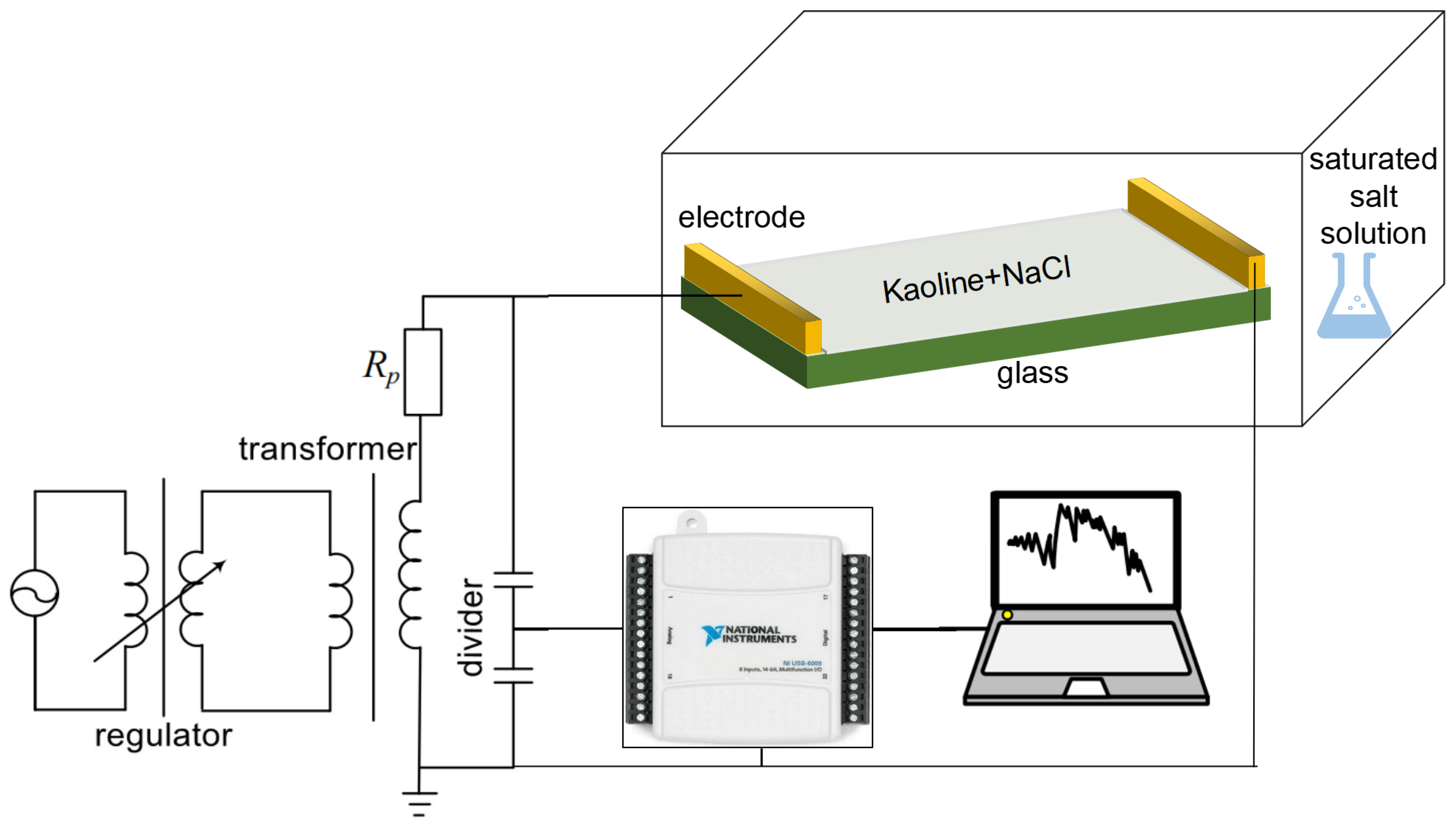
To validate the predicted nonsinusoidal characteristics of leakage current and the existence of a DC component based on the Suwarno equivalent circuit model, this study designed and conducted a series of laboratory simulation experiments aimed at reproducing the electrical behavior of an insulator surface under conditions of contamination accumulation and moisture exposure. As shown in Figure 2, the experimental setup primarily consists of a 10 cm × 4 cm glass plate, on the surface of which a simulated contaminant layer was uniformly applied. The contaminant layer, prepared by mixing kaolin and NaCl, was used to replicate the contamination deposition typically observed on the surface of real insulators in coastal, high-salt-fog environments. The contaminant layer had an NSDD of 2.0 mg/cm2 (corresponding to ash or dust density) and an ESDD of 0.1 mg/cm2 (corresponding to salt density). The sample was placed inside a humidity-controlled environmental test chamber, where the relative humidity was maintained stably within the range of 73–78% relative humidity (RH) by placing a saturated NaCl solution, simulating high-humidity conditions. After allowing 12 h for sufficient moisture absorption, two copper foil electrodes were symmetrically attached to both sides of the glass plate to serve as the voltage application and current signal acquisition interfaces, thereby constructing a simple plate-type leakage current circuit. During the experiment, a NI USB6009 data acquisition (DAQ) card, in conjunction with a LabVIEW-based data acquisition system, was used to synchronously acquire the voltage and leakage current signals across the circuit at a high sampling rate of 5000 Hz. This ensured the accurate capture of rapid transients and spike-like distortions in the current waveform.

2.3. Accelerated Corrosion Test with Leakage Current

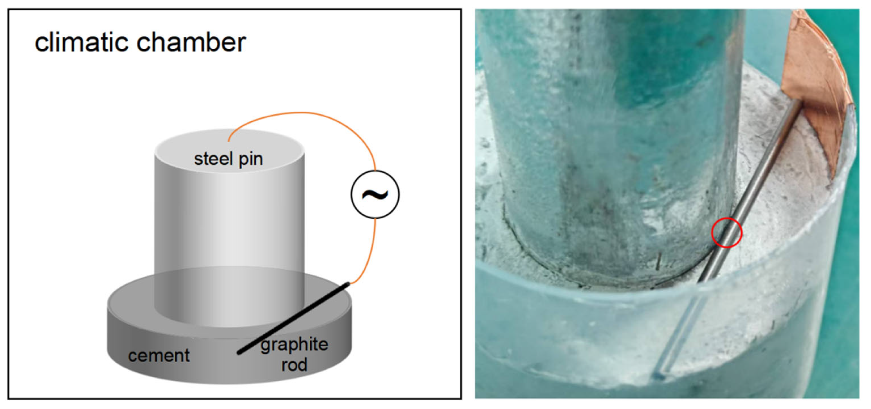
Heat-zinc-galvanized steel-silicate cement specimens (Figure 3) were prepared, and accelerated corrosion tests were conducted in an environmental simulation chamber at 40 °C and 93% RH, in accordance with the standard IEC 60068-2-78:2012 [20]. A standard L9(33) orthogonal array was employed to investigate the main effects and interactions among three experimental factors: salt-spray deposition rate (0, 5, or 10 g·m−2·day−1), acetic acid pollution level (0, 3, or 8 µg·m−3), and alternating leakage current (0, 3, or 10 mA). For each test condition, two identical specimens were prepared, resulting in a total of 18 samples. The testing sequence was randomized to ensure statistical orthogonality and minimize potential bias. An AC current was directly injected into the root of the steel pin using a graphite electrode, where the cylindrical graphite electrode made point contact with the cylindrical steel pin, as shown by the red circle in Figure 3. The test results were subjected to correlation analysis involving confidence levels and response surfaces. Detailed test procedures are provided in our previous work [21].

2.4. Simulation of Leakage Current Mitigation Using Semiconducting Coating

This study employs COMSOL Multiphysics v5.6, to perform numerical calculations on a three-dimensional steel pin model. Based on the Electric Currents module, the influence of a semiconducting coating on the leakage current distribution around the steel pin was investigated. The electrical conductivity of carbon steel was set to 106 S/m, and that of cement was set to 10−12 S/m. A total injection current of 125 μA was applied through a cylindrical electrode with a radius of 0.2 mm.

3. Results and Discussion

3.1. Case Analysis of Broken Strings

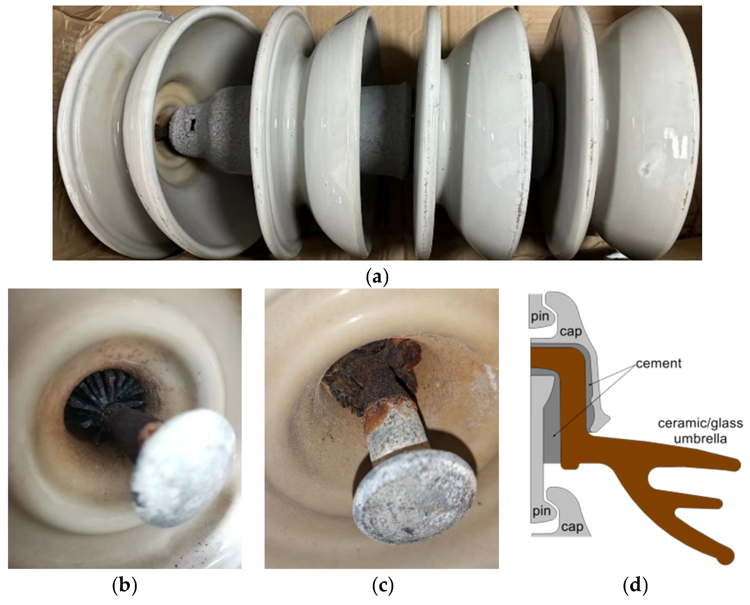
During the routine line inspection conducted by China Southern Power Grid Hainan Branch in 2023, a broken string incident involving the fourth porcelain insulator was identified on a 220 kV transmission line, as shown in Figure 4a–c. The insulator string was commissioned in 2010 and is located in Huifeng Town, Wenchang City, Hainan Province, which features a typical marine climate characterized by high temperature, high humidity, and high salt fog. On-site investigations revealed that multiple steel pins within the insulator string exhibited varying degrees of corrosion, with the corrosion areas primarily concentrated near the interface between the steel pin and the cement grouting material. Notably, the corrosion severity showed relatively little variation among different insulator units, and no clear correlation with the electric field gradient along the insulator string was observed (The electric field strength along the length of an insulator typically exhibits a U-shaped distribution, with relatively higher field intensities near the steel pins at both ends). This observation suggests that the corrosion of the steel pins is not primarily caused by non-uniform electric field distribution but is closely related to the structural arrangement of the steel pins and their local surface environmental conditions. Compared to the upper-mounted corona rings or steel caps, the steel pins are oriented downward, making them more prone to the accumulation of contaminants and moisture (Figure 4d). Consequently, the surface of the steel pins is more likely to develop a moist and highly conductive contaminant layer. Under such conditions, the leakage current density on the steel pin surface is significantly higher than that on the steel cap and other regions, which serves as a key factor driving localized electrochemical corrosion.

3.2. Results of Leakage Current Simulation and Measurement

Extensive previous research has demonstrated that leakage current is one of the primary contributing factors to electrochemical corrosion in power equipment, transmission lines, and metal components. In coastal operating environments characterized by high salt fog, high humidity, and high temperature, when the surface of a porcelain insulator becomes contaminated and moist, the resulting surface contaminant layer often exhibits significant nonlinear resistive behavior [22]. By varying the nonlinear coefficient α within the Suwarno equivalent circuit model across different ranges (0, 1), (0, 2) and (0, 3), the effects of varying degrees of contamination and moisture, as well as nonlinear electric field responses, on leakage current characteristics were simulated.
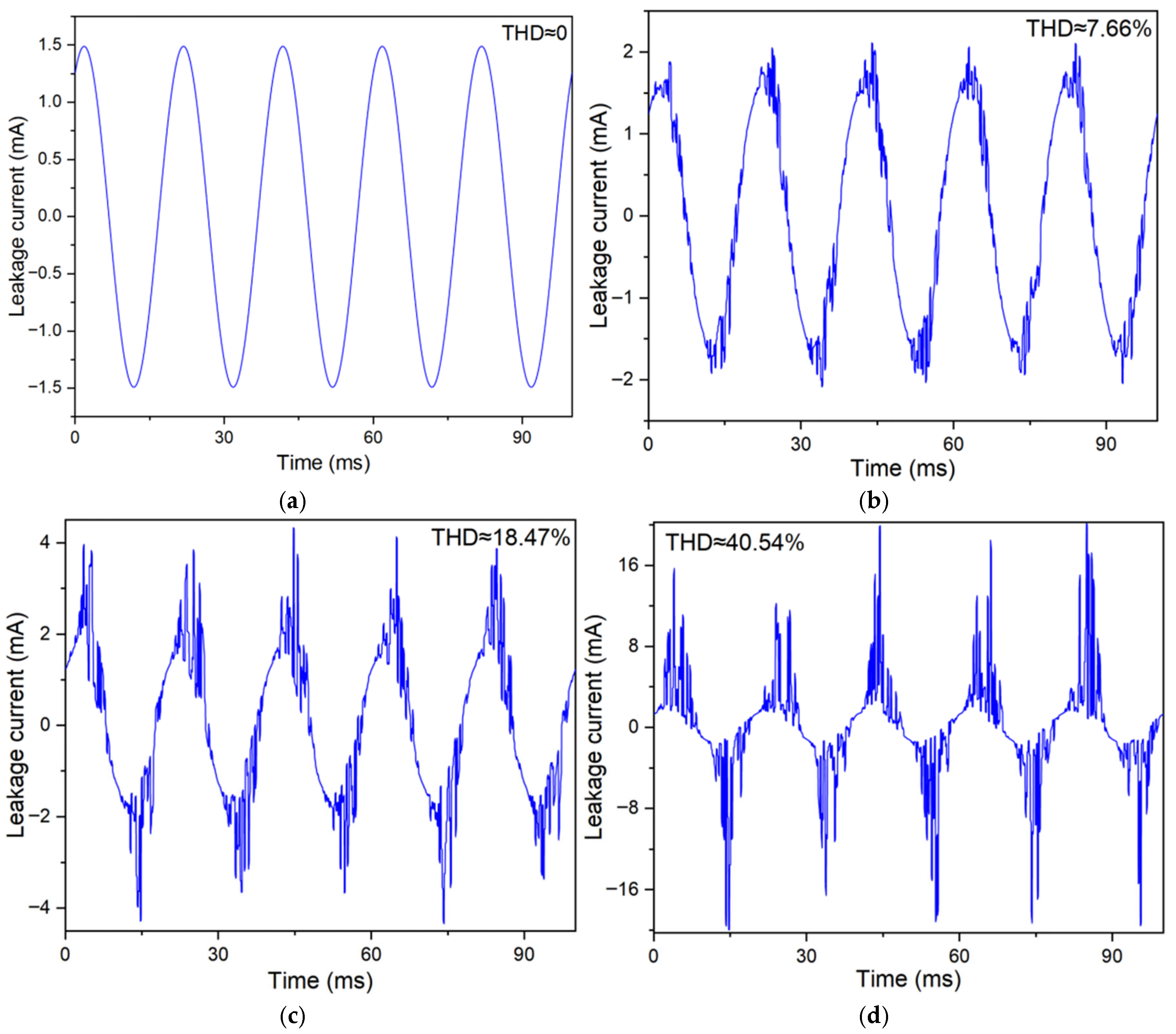
The simulation results presented in Figure 5 indicate that under dry (non-moist) conditions, the leakage current exhibits a standard sinusoidal waveform. However, as the variation range of the nonlinear coefficient α increases from (0, 1) to (0, 2) and then to (0, 3), the waveform of the leakage current progressively deviates from a pure sine wave. Correspondingly, the total harmonic distortion (THD) rises significantly from 7.66% to 18.47% and then to 40.54%, while the peak leakage current increases from 2 mA to 4 mA and further to 18 mA. These findings suggest that the nonlinear response of the contaminant layer on the insulator surface can substantially alter the waveform characteristics of the leakage current, introducing higher-order harmonics and a DC offset component. Such changes exacerbate the deterioration of the electrochemical environment in localized regions, particularly at components such as the steel pin-thereby increasing the risk of localized corrosion.
To closely mimic the actual operating voltage levels of insulators in service, an AC power-frequency voltage of 4.5 kV (rms) was applied across the two ends of a glass plate in the experiment and maintained for a sufficiently long duration (approximately several minutes to tens of minutes). This ensured the formation of distinct dry band regions within the contaminant layer, along with corresponding localized arcing or nonlinear conduction phenomena.
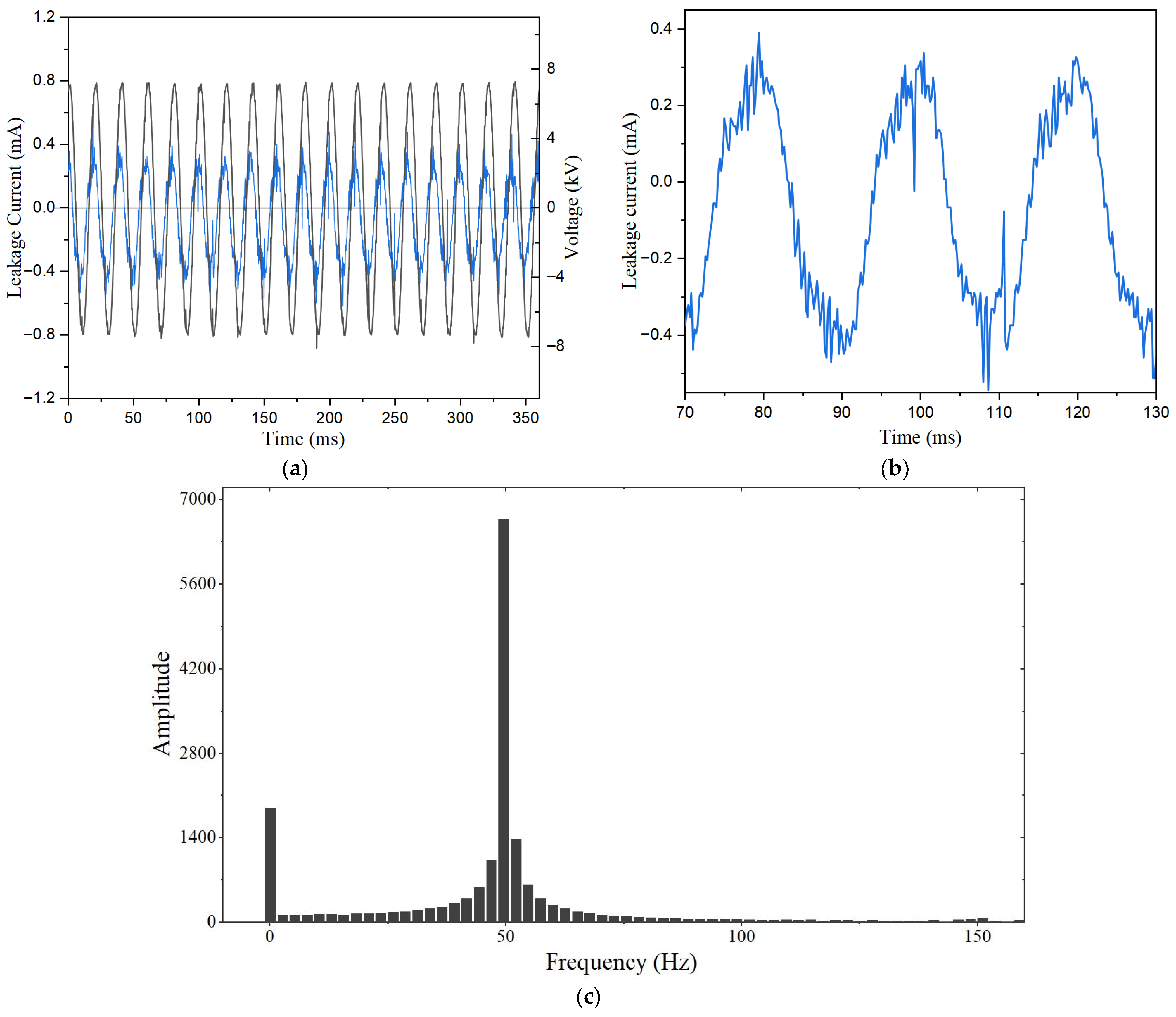
Through post-processing and analysis of the acquired leakage current signals, it can be observed from the voltage-current phase difference shown in Figure 6a (the black line is voltage and the blue line is current) that the leakage current is predominantly resistive, with a minor capacitive component. As illustrated in Figure 6b, under prolonged exposure to moisture and voltage stress, the measured leakage current waveforms display significant non-sinusoidal distortion. This distortion is characterized by distinct spike-like protrusions near the peaks and valleys of the otherwise sinusoidal waveform. These transient distortions occur randomly in time and are marked by localized regions of high amplitude. Further Fourier analysis of the current signals revealed that the major energy of the leakage current was concentrated at frequencies of 100 Hz and below, and a noticeable DC offset component was present, as shown in Figure 6c. Quantitative analysis showed that the DC component accounted for approximately 22% of the fundamental current amplitude, with an equivalent DC current magnitude of about 0.045 mA. Notably, these experimental findings are in close agreement with the simulated leakage current characteristics based on the Suwarno model. When the nonlinear coefficient α was set to higher values (e.g., (0, 2) and (0, 3)), the simulated currents also exhibited waveform distortion, increased THD, and the emergence of a DC component. In particular, when α = (0, 3), the simulated leakage current displayed pronounced spike-like transients and a significant DC offset, with the peak current far exceeding the fundamental level (reaching up to 18 mA).

3.3. Results of Accelerated Corrosion Test

Although the total leakage current in the circuit appears relatively low during the experiment, the contact between the steel pin and the contaminant layer is often point-like or limited to a small area. As a result, the local current density may far exceed the corrosion threshold (e.g., 100 A/m2)—particularly under the combined influence of high temperature, high humidity, and salt fog. These conditions can readily induce pitting corrosion, pit corrosion, and even localized perforation, ultimately threatening the mechanical connection reliability of the insulator. The surface morphologies after 40 days of accelerated corrosion are shown in Figure 7. It can be observed that in the three experimental conditions below, corrosion occurred specifically at the contact points between the graphite electrode and the steel pin, while no significant corrosion was observed in the surrounding areas.
Among these, Figure 7a corresponds to the case without the influence of AC leakage current, whereas Figure 6b,c involves the presence of AC leakage current. It is evident that the volume of corrosion products in the latter cases (with leakage current) is significantly greater than that in the former (without leakage current). The corrosion in Figure 7a can be primarily attributed to galvanic corrosion between the graphite and carbon steel, while Figure 7b,c involves additional effects from AC leakage current. Although the total leakage current in the circuit remains relatively low, the approximate point contact between the graphite electrode and the cylindrical steel pin can result in a localized current density amplified by tens or even hundreds of times—potentially far exceeding the threshold for AC corrosion (100 A/m2). We speculate that when the metal is overprotected (with the zinc potential at −1.10 V (CSE)), although a complete protective film forms, it may eventually rupture due to the oscillating effects of the AC and fluctuations in the instantaneous potential. When exposed to high temperature, high humidity, and salt spray environments, this can lead to pitting corrosion. The resulting metal oxides generated from corrosion can adhere to the cement surface, creating localized short-circuit paths and further increasing the likelihood of leakage current concentration at these sites. Over time, this process can lead to corrosion morphologies similar to those shown in Figure 4b,c. For leakage currents containing both AC and DC components, the AC component first damages the protective layer, after which the DC component induces Faradaic corrosion at the pitting sites.

3.4. Results of Current Density Distribution and Mitigation

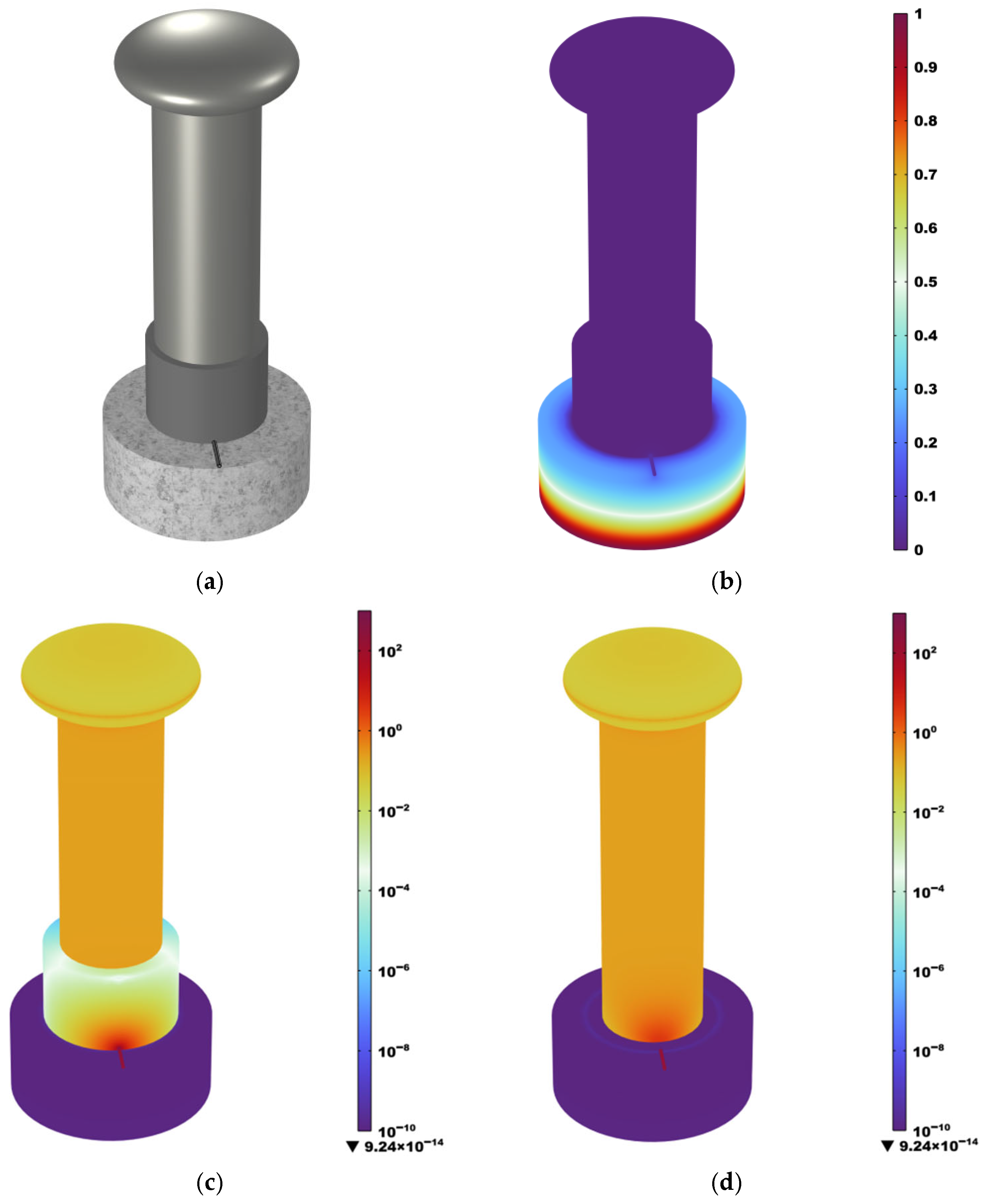
Therefore, for the corrosion protection of metals under high electric fields, relying solely on alloy-based coatings is insufficient. It is essential to avoid localized increases in current density. To address this, we propose applying a semiconducting silicone rubber coating at the root of the steel pin—leveraging its excellent weather resistance—to achieve current equalization. The effects of coating parameters on current equalization performance were quantitatively investigated through simulations. According to relevant domestic and international studies, the distribution of contaminants on insulator surfaces is non-uniform. Due to the effects of gravity, wind direction, and dielectrophoretic forces, the contamination near the steel cap and pin is significantly heavier than that near the insulator edges, with local surface conductivity reaching as high as ~10−4 S [23]. To ensure that the majority of leakage current flows through the volume of the semiconductive coating, its volume conductivity should exceed 10−4 S/m. Figure 8a presents the three-dimensional finite element simulation model, in which a cylindrical electrode with a radius of 0.2 mm injects a current of 25 μA into the steel pin from the cement grouting interface. The current flows from the cement (high-voltage side) toward the steel frame (low-voltage side), simulating the actual leakage current path during service. Figure 8b shows the normalized potential distribution, while Figure 8c,d present the current density distributions on the surface of the coating and on the surface of the steel pin beneath the coating, respectively, for a coating thickness of 2 mm and a conductivity of 10−2 S/m. The results show that both the steel pin and the coating exhibit high current density concentrations near the injection point, spreading out in a fan-shaped pattern.
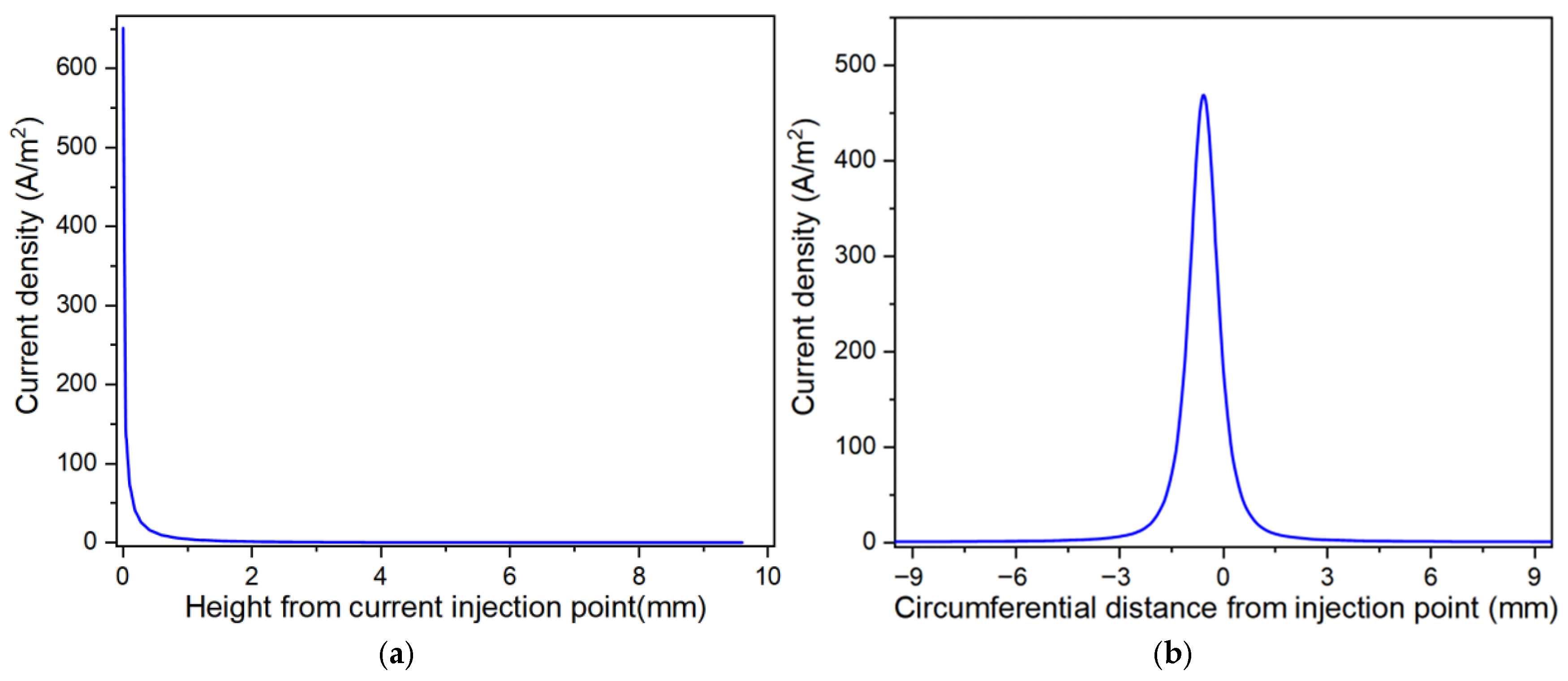
To further reveal the current equalization effect of the coating, we extracted the line distribution of current density near the current injection point. Without the coating, where the electrode is in direct contact with the steel pin, the current density distributions along the height and axial directions are shown in Figure 9a and Figure 9b, respectively. The peak current density at the injection point reaches approximately 500 A/m2 (due to mesh averaging, the actual value may be even higher). Such a high localized current density far exceeds the corrosion resistance capability of the steel substrate and can readily induce pitting corrosion and localized perforation. With the coating applied, the maximum current density decreases significantly with increasing coating thickness. Notably, when the coating thickness is fixed and the conductivity is varied within the range of 10−4 to 102 S/m, the current density distribution curves remain largely unchanged. This indicates that when there is a large conductivity contrast between the coating and the steel pin substrate (approximately 106 S/m), the current equalization effect of the coating is primarily determined by its thickness, while the impact of conductivity is relatively minor. Moreover, the height of the coating applied along the steel pin (5 mm, 10 mm, and 15 mm) has no significant effect on the maximum current density at the steel pin. This can actually be observed from Figure 9a, where the current density decreases rapidly within the first 2 mm above the steel pin.
When the coating thickness is 0.5 mm, the maximum current density on the steel pin surface drops sharply from 500 A/m2 to 46 A/m2. When the thickness is increased to 2 mm, the maximum current density further decreases to approximately 5 A/m2. When the thickness is further increased to 3 mm, the current density drops to around 2 A/m2, which is within the safe range and shows a trend toward saturation. From the perspectives of both current equalization performance and cost-effectiveness, it is recommended that the thickness of the semiconducting protective coating should be at least 2 mm. We reviewed the relevant specifications from power grid authorities regarding the thickness of RTV coatings applied to the surface of porcelain insulators, which is typically in the range of 0.3~0.5 mm. Taking all factors into consideration, it is recommended applying a 2 mm-thick, 10 mm-high semi-conductive coating at the base of the steel pin.
Furthermore, considering that leakage current should preferably conduct volumetrically rather than superficially, the conductivity of the coating should be controlled around 10−4 S/m (which can be achieved by filling 15 phr of nano-acetylene black) [24]. This conductivity level is sufficient to ensure volumetric current conduction, while avoiding unnecessary cost increases associated with excessively high conductivity.

4. Conclusions

This study investigates the corrosion behavior of AC insulator steel pins under coastal, hot and humid conditions, focusing on the role of leakage current and the effectiveness of surface coatings. Accelerated tests were conducted to simulate nonlinear leakage currents with corrosive DC and high-density AC components, which concentrate at the steel pin–cement interface and form localized high-current zones driving corrosion.
Semiconducting silicone rubber coatings were found to effectively suppress corrosion by blocking and redistributing the leakage current, keeping the steel pin current density below the critical corrosion threshold. A coating thickness of ≥2 mm was identified as crucial for uniform current distribution, significantly reducing peak current density, while conductivity (10−6~1 S/m) had a minor impact. These findings highlight the importance of proper coating design, particularly thickness control, in mitigating AC leakage current-induced corrosion. Long-term field validation is needed, and semi-conductive RTV coatings will be applied to selected in-service insulators during the Hainan Power Grid maintenance period for evaluation under real operating conditions.

Author Contributions

Conceptualization, C.Z. and Z.S.; methodology, H.Z. (Heng Zhong); software, Y.Y.; validation, H.Z. (Heng Zhong), X.F. and C.Z.; formal analysis, Z.S.; investigation, H.Z. (Hongyan Zheng); resources, C.Z. and Y.Y.; data curation, X.F.; writing—original draft preparation, C.Z. and Z.S.; writing—review and editing, Z.S. and Y.Y.; visualization, Y.Y.; supervision, J.S.; project administration, J.S. and H.Z. (Heng Zhong); funding acquisition, C.Z. All authors have read and agreed to the published version of the manuscript.

Funding

This research received no external funding.

Data Availability Statement

Data can be made available upon request.

Conflicts of Interest

Authors Cong Zhang, Hongyan Zheng, Junbin Su, Heng Zhong and Xiaotao Fu were employed by the company Electric Power Science Research Institute, Hainan Power Grid Co., Ltd. The remaining authors declare that the research was conducted in the absence of any commercial or financial relationships that could be construed as a potential conflict of interest.

References

  1. Kluss, J.; Chalaki, M.R.; Whittington, W.; Rhee, H.; Whittington, S.; Yadollahi, A. Porcelain Insulation—Defining the Underlying Mechanism of Failure. High Volt. 2019, 4, 81–88. [Google Scholar] [CrossRef]
  2. Kim, T.; Lee, Y.-J.; Sanyal, S.; Woo, J.-W.; Choi, I.-H.; Yi, J. Mechanism of Corrosion in Porcelain Insulators and Its Effect on the Lifetime. Appl. Sci. 2020, 10, 423. [Google Scholar] [CrossRef]
  3. Wang, C.; Qin, G. Corrosion of Underground Infrastructures under Metro-Induced Stray Current: A Review. Corros. Commun. 2024, 14, 23–38. [Google Scholar] [CrossRef]
  4. Huang, Z.; Feng, C.; Wang, J.; Liu, W.; Xie, Y. Research on Metal Corrosion Mechanism and Inhibition Measures of Transmission and Distribution Equipment in Hunan. IOP Conf. Ser. Earth Environ. Sci. 2021, 621, 012035. [Google Scholar] [CrossRef]
  5. Salem, A.A.; Lau, K.Y.; Rahiman, W.; Abdul-Malek, Z.; Al-Gailani, S.A.; Rahman, R.A.; Al-Ameri, S. Leakage Current Characteristics in Estimating Insulator Reliability: Experimental Investigation and Analysis. Sci. Rep. 2022, 12, 14974. [Google Scholar] [CrossRef] [PubMed]
  6. Pratomosiwi, F. Electrical Equivalent Circuit of Ceramic Insulators with RTV Silicone Rubber Coating and Computer Simulation of Leakage Currents. WSEAS Trans. Circuits Syst. 2009, 8, 360–369. [Google Scholar]
  7. Segall, S.M.; Bahgat, H.; Gudino, E.; Boudreault, J.P.; Khattar, C.; Chen, S. Challenges in Implementing SP21424-2018 AC Corrosion Criteria. In Proceedings of the CORROSION 2021, AMPP: Virtual Conference, Salt Lake City, UT, USA, 19–30 April 2021; pp. 1–14. [Google Scholar]
  8. Galimberti, C.E. Corrosion of Lead by Alternating Current. Corros. Eng. Dig. 1965, 14, 212–218. [Google Scholar] [CrossRef]
  9. Han, Y.; Xia, Y.; Chen, X.; Sun, L.; Liu, D.; Ge, X. Effect of Rare Earth Lanthanum-Cerium Doping on Corrosion Behavior of Zinc-Aluminum-Magnesium Hot-Dip Galvanizing Coatings Used for Transmission Towers. Anti-Corros. Methods Mater. 2018, 65, 131–137. [Google Scholar] [CrossRef]
  10. Vagramyan, A.T.; Sutyagina, A.A. The Effect of Alternating Current on the Electrodeposition of Nickel. Russ. Chem. Bull. 1953, 1, 399–402. [Google Scholar] [CrossRef]
  11. Zhang, J.; Ji, S.; Ou, X. Representation Method of Insulator Pollution Degree Based on Leakage Current Fundamental Resistive Component. High Volt. Appar. 2010, 46, 29–33+39. [Google Scholar] [CrossRef]
  12. Fu, C.; Hu, J.; Yang, D.; Yang, B.; Shuang, K.; Zhao, J.; Han, E.; Ke, W. Survey on Soil Corrosion of Grounding Grid of Power Substations in Hainan Island. Corros. Sci. Prot. Technol. 2017, 29, 97–102. [Google Scholar]
  13. Masri, M.N.; Yunus, Z.M.; Warikh, A.R.M.; Mohamad, A.A. Electrical Conductivity and Corrosion Protection Properties of Conductive Paint Coatings. Anti-Corros. Meth Mater. 2010, 57, 204–208. [Google Scholar] [CrossRef]
  14. Xu, L.Y.; Su, X.; Yin, Z.X.; Tang, Y.H.; Cheng, Y.F. Development of a Real-Time AC/DC Data Acquisition Technique for Studies of AC Corrosion of Pipelines. Corros. Sci. 2012, 61, 215–223. [Google Scholar] [CrossRef]
  15. Luo, L.; Wang, L.; Guan, Z.; Zhang, F.; Li, L. Influence of Pin Corrosion on Mechanical Characteristic of UHVDC Disc Suspension Insulators and Solutions. IEEE Trans. Dielect. Electr. Insul. 2015, 22, 2242–2251. [Google Scholar] [CrossRef]
  16. Ren, Z.; Yang, D.; Liu, J.; Ma, Y.; Huo, Z.; Zheng, S. The Protection of 500 kV Substation Grounding Grids with Combined Conductive Coating and Cathodic Protection. Anti-Corros. Methods Mater. 2015, 62, 83–87. [Google Scholar] [CrossRef]
  17. Rachmawati, R.; Sartika, N.; Meisa Putra, N.R.; Suwarno, S. The Study on Leakage Current Characteristics and Electrical Properties of Uncoated Ceramic, RTV Silicon Rubber Coated Ceramic, and Semiconducting Glazed Outdoor Insulators. Int. J. Electr. Eng. Inform. 2018, 10, 318–336. [Google Scholar] [CrossRef]
  18. Rahim, N.A.A.; Ranom, R.; Zainuddin, H.; Razak, I.A.W.A. Numerical Simulation of Leakage Current on Conductive Insulator Surface. Int. J. Recent Technol. Eng. 2019, 8, 9487–9492. [Google Scholar] [CrossRef]
  19. Salhi, R.; Mekhaldi, A.; Teguar, M.; Kherif, O. Impact of Nonlinear Material Integration in 400 kV Composite Insulator on Leakage Current and Electric Field Distribution. In Proceedings of the 2nd National Conference on Electronics, Electrical Engineering, Telecommunications, and Computer Vision, C3ETCV’24, Mila, Algeria, 24–25 November 2024. [Google Scholar]
  20. IEC 60068-2-78; Environmental Testing—Part 2–78: Tests—Test Cab: Damp Heat, Steady State. IEC: Geneva, Switzerland, 2012.
  21. Zhang, C.; Zhong, H.; Shen, Z.; Zheng, H.; Yang, Y.; Su, J.; Fu, X. Accelerated Corrosion and Multimodal Characterization of Steel Pins in High-Voltage AC Insulators under Multi-Stress Conditions. Materials 2025, 18, 4218. [Google Scholar] [CrossRef] [PubMed]
  22. Zhicheng, G.; Yingke, M.; Liming, W.; Ruihai, L.; Hua, W.; Yi, M. Leakage Current and Discharge Phenomenon of Outdoor Insulators. Int. J. Electr. Eng. Inform. 2009, 1, 1–17. [Google Scholar] [CrossRef]
  23. Cao, B. Study on Novel Method to MeasurePartial Equivalent Salt Deposit Densityon the Surface Ofinsulators; Tsinghua University: Beijing, China, 2016. [Google Scholar]
  24. Kumar, V.; Alam, M.N.; Manikkavel, A.; Song, M.; Lee, D.-J.; Park, S.-S. Silicone Rubber Composites Reinforced by Carbon Nanofillers and Their Hybrids for Various Applications: A Review. Polymers 2021, 13, 2322. [Google Scholar] [CrossRef] [PubMed]
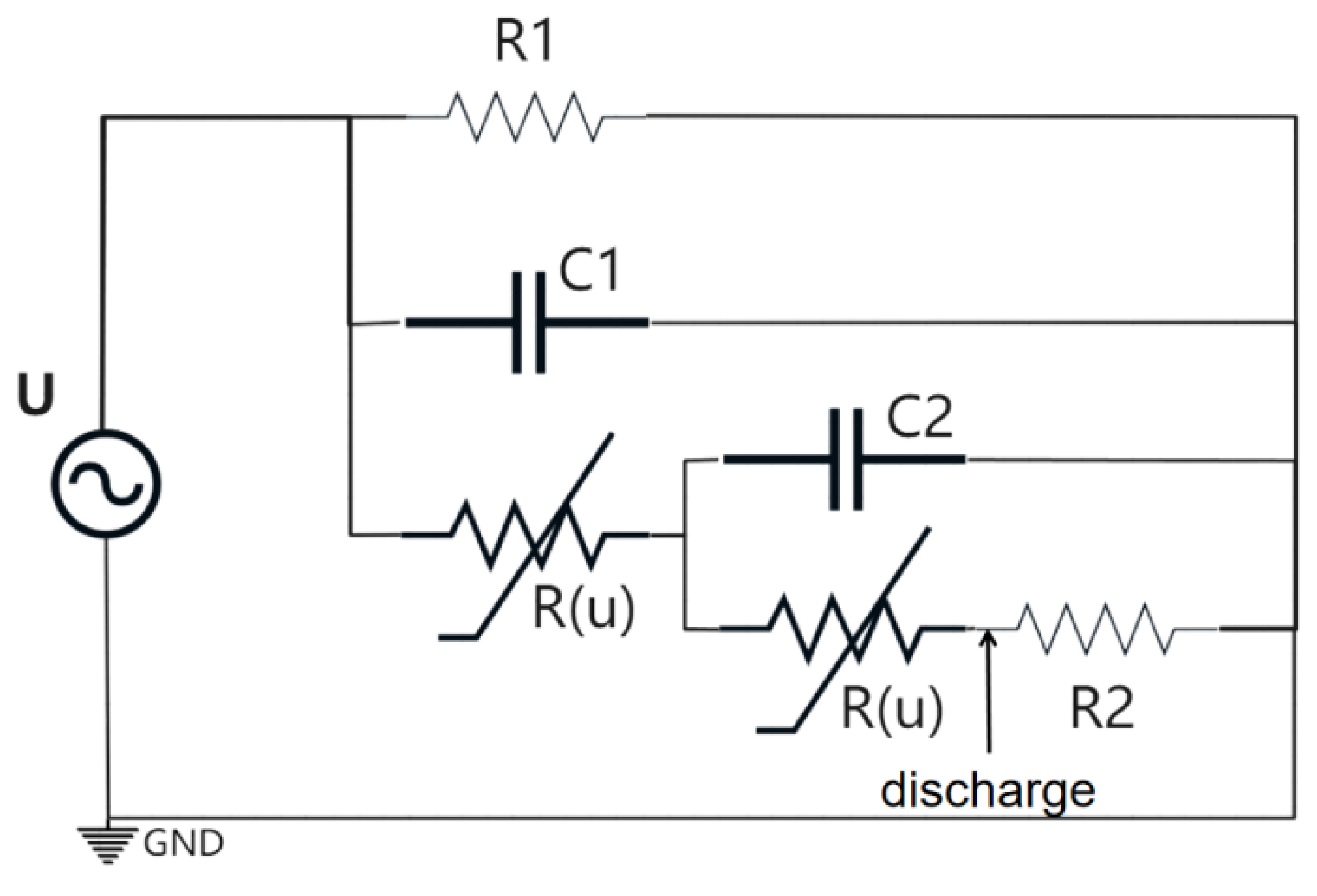
Figure 1. Suwarno equivalent circuit model.
Energies 18 05246 g001
Figure 2. Leakage Current Generation and Acquisition Device for Contaminated and Moistened Surfaces.
Energies 18 05246 g002
Figure 3. Accelerated Corrosion Test Setup.
Energies 18 05246 g003
Figure 4. Failure incident of an insulator string due to steel pin corrosion. (a) Overall view of the insulator string. (b,c) Corroded regions on the steel pins. (d) Cross-sectional view of the insulator (XP-50 type).
Energies 18 05246 g004
Figure 5. Simulated leakage current waveforms based on the Suwarno equivalent circuit. (a) α = 0, (b) α ∈ (0, 1), (c) α ∈ (0, 2), (d) α ∈ (0, 3).
Energies 18 05246 g005
Figure 6. Leakage current measurements on contaminated and moist Surfaces. (a,b) the time-domain waveforms of the current, (c) the frequency components.
Energies 18 05246 g006
Figure 7. Surface morphology after 40 days of accelerated corrosion under different conditions. (a) acetic acid = 3 μg/m3, salt fog = 10 g/m2·day, current = 0; (b) acetic acid = 0, salt fog = 10 g/m2·day, current = 10 mA; (c) acetic acid = 0, salt fog = 3 g/m2·day, current = 5 mA.
Energies 18 05246 g007
Figure 8. Simulation results of the steel pin–cement structure. (a) Schematic of the simulation model, (b) Voltage distribution, (c) Current density distribution on the surface of the semiconducting silicone rubber coating, (d) Current density distribution on the surface of the internal steel pin. (Unit: A/m2).
Energies 18 05246 g008
Figure 9. Surface current density distributions. (a) Surface current density variation with height in the absence of a coating, (b) Surface current density variation with circumferential angle in the absence of a coating, (c) Surface current density variation with height on the steel pin surface under different coating thicknesses and conductivities, (d) Surface current density variation with circumferential angle on the steel pin surface under different coating thicknesses and conductivities.
Energies 18 05246 g009aEnergies 18 05246 g009b
Disclaimer/Publisher’s Note: The statements, opinions and data contained in all publications are solely those of the individual author(s) and contributor(s) and not of MDPI and/or the editor(s). MDPI and/or the editor(s) disclaim responsibility for any injury to people or property resulting from any ideas, methods, instructions or products referred to in the content.