Article

Insights into the Effect of Confinement on Swirling Flow by PIV

1
National Key Laboratory of Science and Technology on Aero-Engine Aero-Thermodynamics, Research Institute of Aero-Engine, Beihang University, Beijing 100191, China
2
Aero Engine Corporation of China Hunan Aviation Powerplant Research Institute, Zhuzhou 412002, China
*
Author to whom correspondence should be addressed.
Energies 2025, 18(19), 5155; https://doi.org/10.3390/en18195155
Submission received: 17 August 2025 / Revised: 20 September 2025 / Accepted: 22 September 2025 / Published: 28 September 2025

Abstract

Confinement with a rectangular cross-section is commonly used to simulate the role of a swirl combustor, yet its effect on swirling flows remains poorly understood. This study investigates the influence of confinement on the isothermal flow field of a counter-rotating swirler. A particle image velocimetry (PIV) system was employed to measure the swirling flow field under varying confinement ratios at an air pressure drop equivalent to 3% of atmospheric pressure. The results reveal two distinct flow patterns, delineated by a critical confinement ratio of approximately 8.92. Detailed analyses of the velocity components, contour distributions, and Reynolds shear stresses were conducted. The two flow patterns are attributed to the wall attachment effect and swirling intensity, respectively. Furthermore, the results confirm that the swirling flow field is primarily governed by the confinement ratio.

1. Introduction

The swirl cup is a critical component in aircraft engines and industrial furnaces, enhancing fuel atomization, flame stabilization, and air-fuel mixing. Swirling flow is generated by introducing a tangential velocity component, creating a pressure drop along the axis. This results in a sufficient adverse pressure gradient to form a central recirculation zone (CRZ), which emerges only beyond a critical swirl number (approximately 0.6) [1]. The CRZ governs flame structure and stabilization, while high-intensity vortices near the swirler exit improve fuel atomization and mixing.
Extensive studies have characterized swirling flows due to their engineering significance. The existing research can be divided into two main categories: one focuses on the structural parameters of the swirler, such as vane angle, geometry, and hub size [2,3,4,5,6,7,8,9,10], while the other investigates boundary and testing conditions (e.g., inflow turbulence, confinement effects) [11,12,13,14,15,16].
The combustor-to-swirler size ratio is a key parameter in swirling flow combustors. However, few studies systematically examine confinement effects on flow fields. Beltagui and Maccallum [17,18] concluded that the CRZ dimensions are a function of the furnace diameter (enclosure width), and not of the swirler exit diameter for highly confined swirling flow. Herff et al. [19] compared confined and unconfined swirling jets and observed that confinement induces a precessing vortex core (PVC) downstream of the injection tube, significantly altering the flow topology. The confined case exhibited stronger vortex breakdown and larger recirculation zones than the unconfined case. Khalil et al. [20] investigated confinement effects on swirl-assisted combustion under both reacting and non-reacting conditions. They found minimal recirculation in unconfined flames, whereas confinement drastically enlarged the CRZ, improving flame stability. Archer et al. [21,22] experimentally demonstrated that confinement enhances the radial spread of the CRZ. They found that the CRZ in confined cases extends further outward due to increased flow recirculation, improving flame anchoring in combustors. Santhosh et al. [23] used PIV to study non-reacting coaxial swirling jets under two confinement ratios (1.82 and 2.73). Their results demonstrated that increasing the confinement ratio significantly alters vortex dynamics, leading to stronger recirculation and modified flow structures. Nogenmyr et al. [24] conducted numerical simulations and experiments on confined and unconfined swirl flows. Their results showed that confinement enlarges the CRZ while also generating a corner recirculation zone (CORZ), which is absent in unconfined configurations. The study highlighted the importance of confinement-induced flow asymmetry. Zhou et al. [25] employed Tomo-PIV and planar PIV to analyze 3D swirling flow structures in a confined chamber (confinement ratio = 1.53). They observed that confinement compresses the CORZ and induces a reverse-rotation flow, restricting the CORZ’s shape. Their study provided detailed insights into confinement-induced flow asymmetries. Cai et al. [26] conducted an LDV study on swirl cups installed in square test sections. Their data revealed that confinement distorts the flow symmetry and shifts the CRZ location. However, their study was limited to square confinements with a narrow range of test conditions. Fu et al. [27] performed LDV measurements on a counter-rotating swirl cup within a rectangular confinement simulating gas turbine combustor geometries. Their results indicated that confinement significantly modifies mean and turbulent flow properties, including increased turbulence intensity near the confinement walls. Fu and Jeng [28] investigated the influence of confinement on the flow field of a helical-blade swirler using LDV. They designed square confinements of varying sizes, and the results showed that the flow field is highly sensitive to confinement. Additionally, the size of the CRZ increased with the confinement ratio.
These studies have significantly advanced our understanding of the general effects of confinement. However, they are primarily limited to comparative analyses between broadly “confined” and “unconfined” states, or they investigate only a very narrow range of confinement ratios (e.g., [23] studied two ratios). Furthermore, some studies [26,28] employed square confinements, which differ significantly from the rectangular geometries that better simulate the cross-section of a can-type combustor or the sector of an annular chamber. Critically, a systematic investigation mapping the evolution of flow structures across a wide and continuous range of confinement ratios—particularly for the complex flow generated by dual-stage counter-rotating swirlers—is still absent from the literature. This gap prevents the establishment of a generalized relationship between confinement geometry and flow response, which is crucial for combustor design.
To bridge this research gap, the present study employs a simplified rectangular confinement geometry. The width and height of this confinement are designed to fundamentally represent the key geometric constraints encountered in an annular combustor: the width simulates the spacing between adjacent swirlers, while the height simulates the combustor dome height. This approach allows for the systematic isolation and investigation of the confinement ratio effect, which is defined as the area ratio of the confinement cross-section to the swirler exit area, without the additional complexity introduced by full annular geometry and curvature effects. While this simplification does not capture all aspects of a real engine combustor, it provides a controlled and optically accessible platform to elucidate the fundamental physics governing confinement effects, which is a critical first step towards understanding more complex real-world configurations.
To address this gap, this paper designs seven rectangular confinements with different confinement ratios ranging from 5.09 to 15.61. Particle image velocimetry (PIV), which enables full-field and transient flow measurements and is widely used for combustor flow field analysis [29,30,31,32], was employed to systematically investigate the confinement effects on the flow characteristics of a dual-stage counter-rotating swirler. Unconfined swirler data serve as a reference. Velocity/vector contours, component velocity distributions, and Reynolds shear stresses are analyzed to elucidate confinement-driven flow modifications.

2. Experimental Setup

Figure 1 presents the schematic of the experimental setup, which comprises an air supply system that includes: a compressor (0.2 kg/s at 0.8 MPa), a dryer, a filter, regulating valves, and a 2 m3 air tank. After drying and filtration, a portion of the air is supplied to the swirler, while another portion is diverted to a fluidized bed seeder. In the seeder, the seeding particles are picked up by the air flow and subsequently combined with the main airflow. The mass flow rate, temperature, and pressure drop of the supplied air were measured near the swirler assembly.
The swirler assembly primarily consists of an outer swirler, inner swirler, nozzle, venturi, and conical flare. The outer and inner swirlers are arranged in a counter-rotating configuration, yielding a global swirl number of 0.83. The swirl intensity is characterized by the swirl number, Sn, a dimensionless parameter calculated according to the classical momentum-based definition through integration of the velocity field at the swirler exit, as established in foundational literature on swirl flows [33].
Velocity measurements were performed using the PIV technique. This method involves illuminating a flow plane with a laser sheet, enabling the tracking of particles (olive oil droplets in the present study, with a diameter of approximately 2 μm). The particles become clearly visible, allowing their positions to be detected and recorded by a camera. By capturing two images of the illuminated flow field, the motion of a given particle can be reconstructed over a predefined time interval, from which the velocity is derived.
The PIV system consists of a pulsed Nd:YAG laser (Newwave, Fremont, CA, USA), a charge-coupled device (CCD) camera (LaVision, PCO-TECH Imaging GmbH, Kelheim, Bavaria, Germany; 14-bit, 4 Mpixels) [34]. In this configuration, the camera axis was set perpendicular to the laser sheet, which was focused on the plane containing the swirler axis. Each laser pulse had an energy of 60 mJ. Double images were acquired with a time interval of 8 μs between exposures. The average particle displacement was maintained at approximately 10 pixels, with an interrogation area of 32 × 32 pixels. After optimization, a minimum of 350 image pairs were recorded per test to ensure statistically robust flow field data. The images were post-processed using DaVis 7.2 software (LaVision). Appropriate correlation algorithms were applied to derive the velocity field.
The geometric parameters of the rectangular plexiglass confinement are summarized in Table 1, where X, Y, and Z denote the confinement length, width, and height, respectively, while D (30 mm) represents the swirler exit diameter.
To facilitate comparative analysis, all dimensions were normalized by the swirler diameter (D). As indicated in Table 1, the experimental configurations can be categorized into two groups with a fixed X/D ratio of 3: (1) Cases with varying Y/D from 2 to 3.5 while maintaining constant Z/D, and (2) Cases with equivalent variations in both Y/D and Z/D. This selection methodology was designed to cover values within the reasonable operational range of actual engine combustor confinement configurations.
The selected Y/Z range of 1 to 1.75 was determined based on the characteristic dimensional ratios between swirler spacing and combustor dome height observed in actual aircraft engine combustor designs across various models.
The experimental setup employed a counter-rotating swirler aligned concentrically with the confinement. As illustrated in Figure 2, the coordinate system origin was established at the center of the swirler exit plane. Velocity measurements were conducted on two distinct planes: (1) The axial plane containing the swirler centerline, and (2) A transverse plane located at X/D = 0.2, parallel to the swirler exit plane.
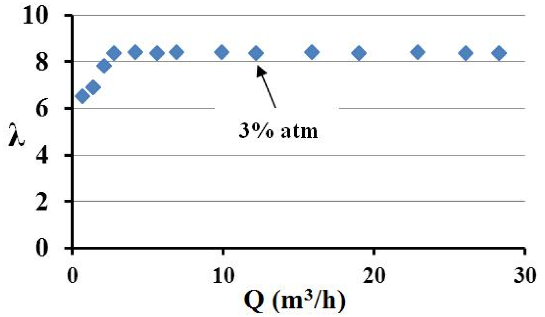
The flow resistance characterization experiment was conducted to identify the self-modeling region required for experimental conditions and operational points, thereby facilitating experimental testing. The self-modeling region corresponds to the quadratic flow resistance zone, where the flow resistance coefficient remains constant with respect to the flow rate Q. The experiment involved measurements of flow rate and inlet pressure. Figure 3 shows the flow resistance characteristic curve of the swirler under unconfined conditions. The horizontal axis represents the flow rate, while the vertical axis represents the flow resistance coefficient. As observed in the figure, the flow resistance coefficient stabilizes at relatively small flow rates, indicating that the flow has entered the self-modeling region.
Considering that the critical point for the swirler to enter the self-modeling region may vary slightly under different configurations, a pressure drop point equivalent to 3% of the atmospheric pressure (∆p = 3000 Pa) was deliberately selected for the tests, corresponding to a flow rate of Q = 12.16 m3/h (all cases reliably entered the self-modeling region under this condition). Furthermore, this 3% pressure drop value realistically simulates the actual pressure drop encountered in practical combustor operation. The flow resistance coefficient is calculated using the following formula:
λ = k Δ p Q 2
where k is a constant determined by the cross-sectional area and fluid density. Under the specified experimental operating conditions, the Reynolds number at the throat of the swirler venturi, with a throat diameter d of 16 mm and a bulk average velocity U0 of 16 m/s, is 19,000.

3. Results and Discussion

The flow structures observed in both measurement planes for the unconfined configuration (Case 8) are presented as a baseline reference for comparative analysis of aerodynamic characteristics in confined flow fields.

3.1. Axial Velocity Contour

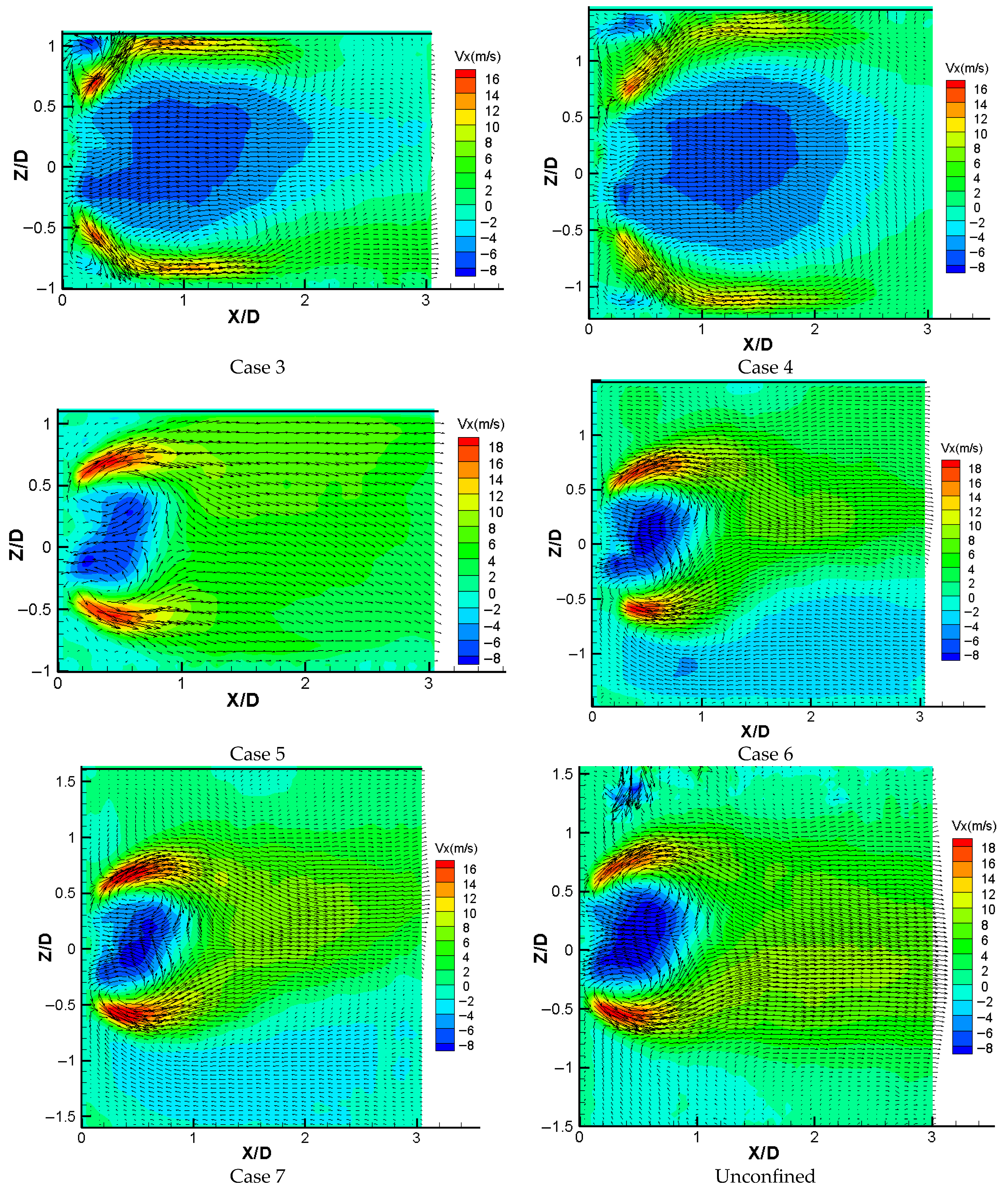
Figure 4 presents a comparative visualization of the flow fields for both confined and unconfined configurations. The results demonstrate that under confinement ratios ranging from 5.09 to 7.64, the flow patterns exhibit remarkable similarity, characterized by swirling flow attachment to the confinement’s inner walls. This wall attachment phenomenon leads to the formation of an expanded CRZ when compared to the unconfined case. Furthermore, all three cases exhibit the presence of dual CORZs within the geometric corners. However, case 4 displays a distinct flow configuration, where these corner recirculation zones undergo significant enlargement relative to those observed in cases 1~3.
A detailed analysis of cases 1~4 reveals an intriguing hydrodynamic trend: while the maximum negative velocity regions (approximately −7 m/s) within the CRZ maintain consistent spatial dimensions regardless of confinement ratio, areas exhibiting intermediate negative velocities (approximately −5 m/s) demonstrate progressive expansion with increasing confinement. The flow characteristics undergo particularly notable transformation in case 5, where the flow field assumes features reminiscent of the unconfined scenario. In this configuration, the CRZ experiences substantial contraction while simultaneously exhibiting elevated injection velocities, accompanied by complete disappearance of the CORZs that were prominent in cases 1~3. Interestingly, cases 5~7 display an inverse relationship, where both CRZ area and negative axial velocity magnitude exhibit gradual enhancement with increasing confinement ratio, ultimately approaching the flow characteristics of the unconfined benchmark case.
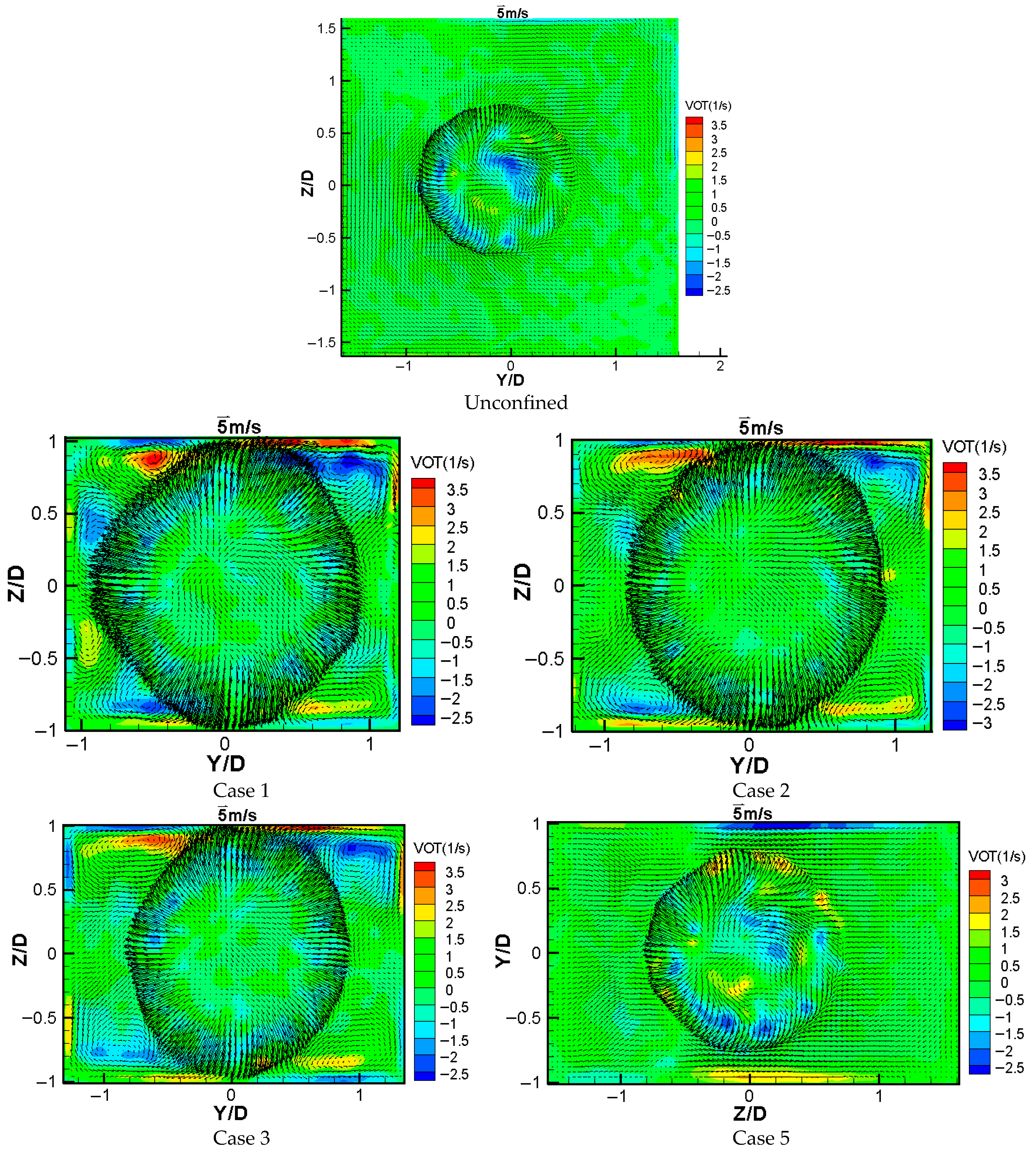
The confinement ratio emerges as a critical parameter governing flow field morphology, particularly when below the threshold value of 8.92. Additional insight comes from examining cases 1~3 and 5, where systematic variation in confinement width (while maintaining constant height) produces consistent modifications in swirling flow structure. These modifications are attributed to the wall attachment mechanism illustrated in Figure 5. Case 1 exhibits comprehensive wall attachment along all four confinement surfaces, while case 3 shows reduced attachment limited to two surfaces, concurrent with diminishment of CORZs. Further supporting this progression, Case 1 demonstrates notably larger radial velocity with pronounced vorticity in the corner recirculation zones (CORZs), whereas with progressively increasing confinement ratio, the radial velocity diminishes substantially alongside a gradual weakening of vorticity intensity. This progression clearly demonstrates the attenuating influence of wall attachment effects with increasing confinement ratio. The transition reaches completion in case 5 (Y/D = 3.5), where wall attachment effects become negligible and the flow field essentially replicates unconfined conditions. This behavioral spectrum suggests that air entrainment and ejection processes play a pivotal role-restricted air supply in low confinement ratio configurations promotes wall attachment, whereas more generous confinement dimensions alleviate this effect.
The observed consistency in flow pattern evolution, whether induced by isolated width (Y/D) variation or combined width-height (Y/D and Z/D) modification, conclusively establishes the confinement ratio (rather than any individual geometric parameter) as the dominant governing factor. Figure 6 quantitatively captures the correlation between confinement ratio and flow field morphology. The graphical representation clearly delineates the systematic transition from pattern 1 to pattern 2 as the confinement ratio escalates, with critical transformation occurring within the range of 7.96 to 8.92.

3.2. Centerline Axial Velocity Distribution

Figure 7 depicts the length of the CRZ, which is determined by the magnitude of the axial velocity at the centerline. For cases 1~4, the length of the CRZ gradually increases, while the negative peak velocity decreases slightly as the confinement ratio increases. This indicates that the adverse pressure gradient gradually decreases, which may be attributed to the weakening of the wall attachment effect. Consequently, it leads to a decrease in vacuum in the central region of the flow field, thereby reducing the axial adverse pressure gradient.
In cases 5~7, both the length and the negative peak velocity of the CRZ increase with the confinement ratio, similar to those of the unconfined case. This suggests that the axial adverse pressure gradient increases gradually, which can be attributed to the enhanced swirling intensity rather than the wall attachment effect observed in cases 1~4. From this perspective, it can be deduced that an optimal confinement ratio is critical for combustion in a swirling-flow combustor. Based on the flow field characteristics and transition patterns observed in this study, the optimal design value is suggested to be slightly greater than the threshold value of 8.92. An oversized combustor may waste space, whereas an undersized combustor would significantly distort the swirling flow pattern due to confinement effects, potentially weakening or even nullifying the swirler’s role in combustion [35].
Additionally, the axial velocity curves for cases 1~4 intersect at approximately X/D = 1.25, indicating that the regions of highest negative axial velocity within the CRZ have nearly identical lengths. Furthermore, the axial velocity curves for cases 5~7 decline at X/D = 2 downstream of the swirl cup exit due to the influence of the confinement walls.

3.3. Velocity Distribution

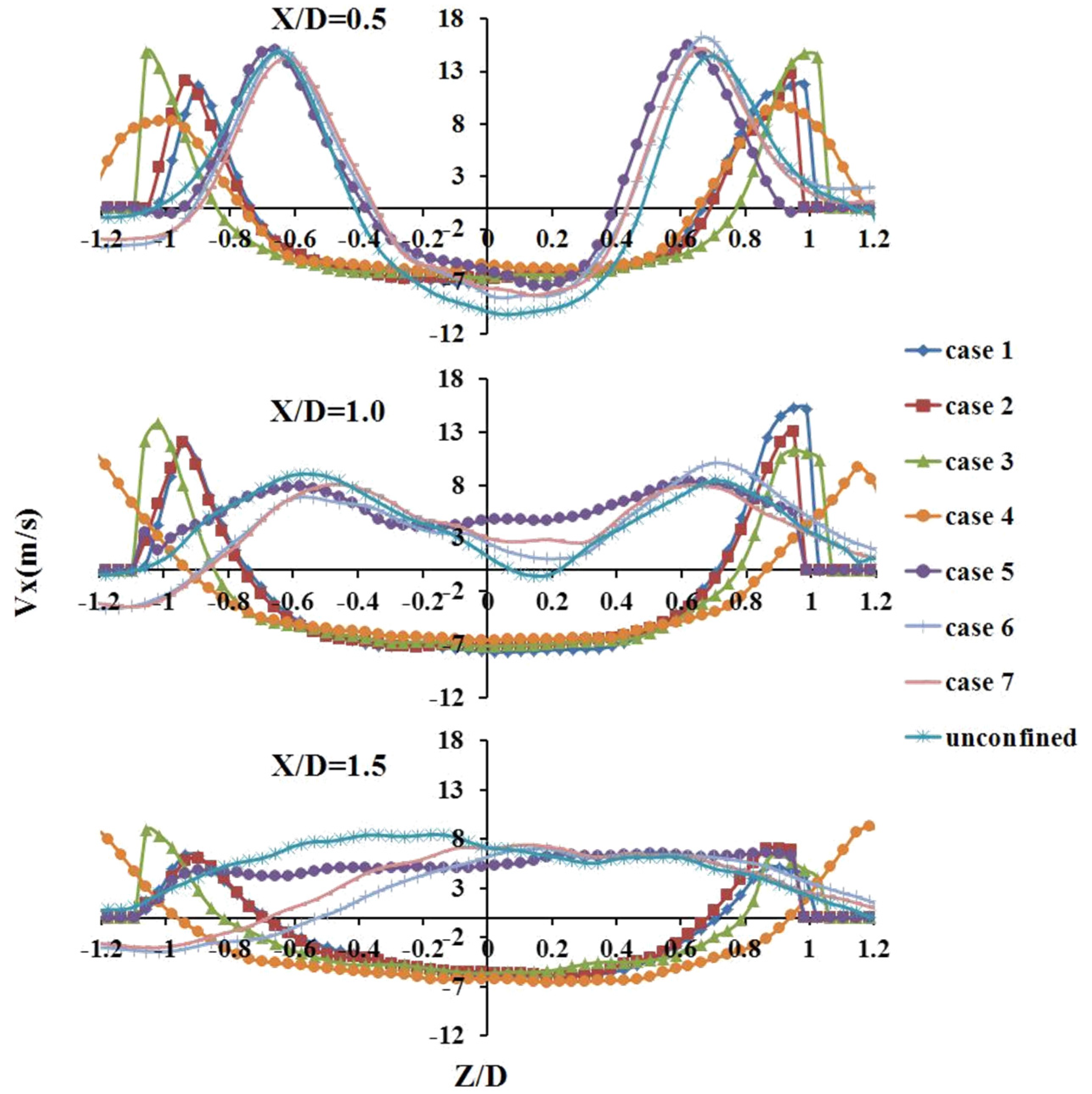
The mean axial velocity distributions at three downstream locations (X/D = 0.5, 1.0, and 1.5) in the center plane (Y = 0) are illustrated in Figure 8. It can be observed that larger diameters of the CRZ, remaining unchanged upstream of X/D = 1.5, occur at the range from Z/D = −0.7 to 0.7 for cases 1–3, with the flow near the confinement wall decaying as the confinement ratio increases. For Cases 1 and 2, the curves coincide well with each other, indicating that the flow pattern remains unchanged when the confinement ratio is less than a certain critical value. The diameters of CRZ increase as the confinement ratio increases for cases 3 and 4 compared with those of cases 1 and 2. When the confinement ratio exceeds 8.92, the velocity curves gradually become uniform and similar to those of the unconfined case at different axial positions. Overall, the velocity curves vary rapidly for cases 5~7, while remaining unchanged for cases 1~4 as the distance downstream from the swirler exit increases, suggesting that the adverse pressure gradient remains consistent and then becomes greater as the confinement ratio rises from 5.09 to 15.61.
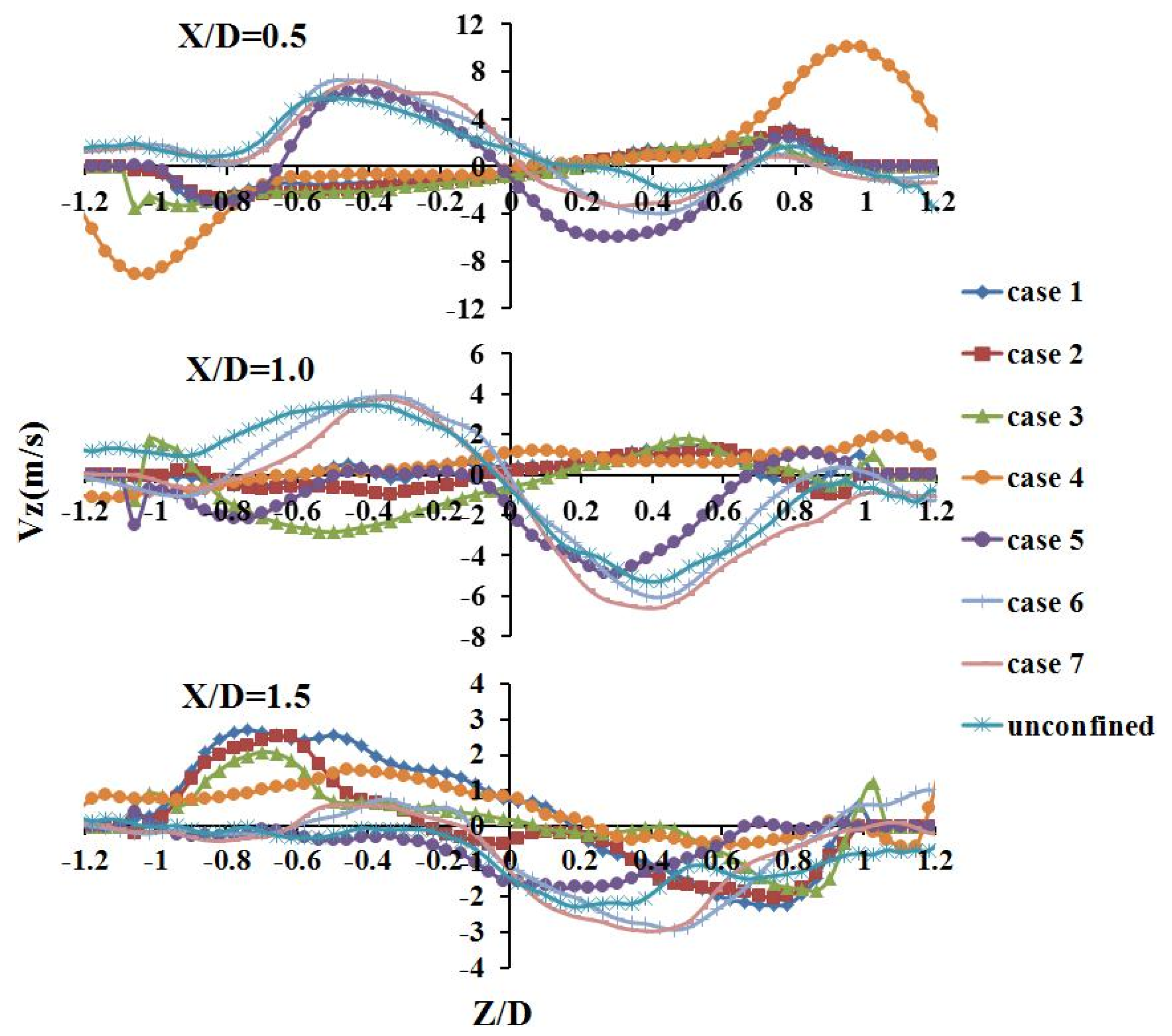
Figure 9 shows the radial velocity distributions at the same axial locations as in Figure 8. Clearly, the radial velocity curves match well within Z/D = −0.7 to 0.7 at X/D = 0.5 for cases 1~4, whereas the radial peak velocity in case 4 is about 3 times higher than that in cases 1~3. This results from the increased height of the confined domain, which enhances the radial velocity. Cases 5~7 exhibit consistent radial velocity distributions analogous to the unconfined case.

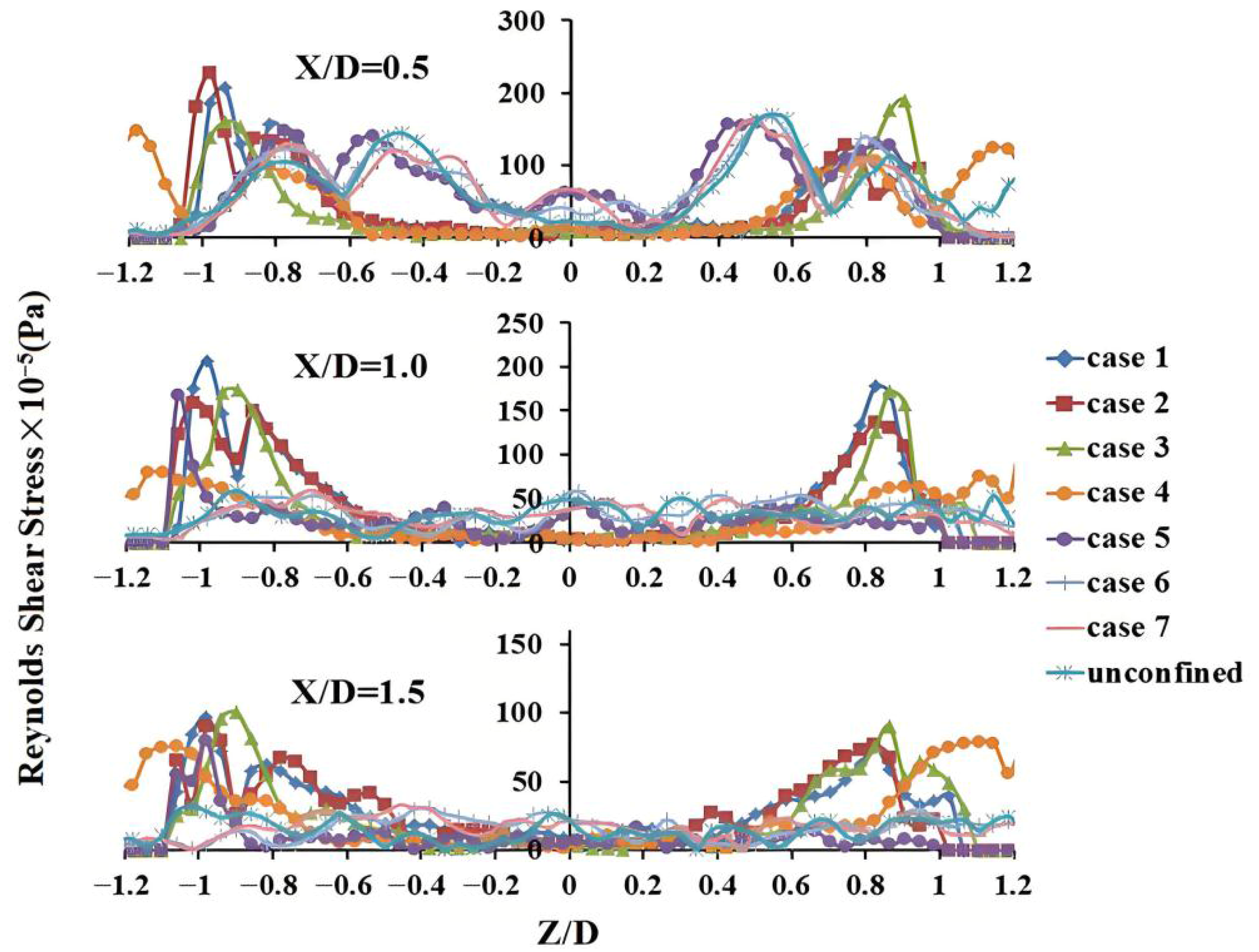
3.4. Reynolds Shear Stress Distribution

Figure 10 shows the distributions of the in-plane Reynolds shear stress component, specifically ρ〈u’v’〉, at the three axial locations. It can be seen that the Reynolds shear stresses remain constant for cases 1~4, with values nearly zero except for two peaks in the ranges of Z/D = −0.6 to −1 and Z/D = 0.6 to 1. As the axial distance increases, the distributions show no significant changes. In contrast, higher Reynolds shear stresses occur at X/D = 0.5 for cases 5~7, indicating that the elevated Reynolds shear stress near the swirler exit enhances atomization of larger fuel droplets.

4. Conclusions

A 2D-PIV system was employed to characterize the isothermal swirling flow field of a counter-rotating swirler. The effect of a confinement ratio was experimentally investigated at an air pressure drop equivalent to 3% of atmospheric pressure, using the unconfined case as a reference to understand the aerodynamics of the confined cases. The results demonstrate that confinement has a significant impact on the swirling flow pattern, generating two distinct flow fields under different confinement ratios.
When the confinement ratio is less than 8.92, the swirling flow moves downstream attached to the inner wall, exhibiting lower axial velocity and a larger CRZ area, while the regions of highest negative axial velocity remain nearly constant. However, as the confinement ratio increases from 8.92 to 15.61, the flow field transitions to a pattern with progressively higher axial velocity and a smaller CRZ area, resembling that of the unconfined case.
Furthermore, Reynolds shear stress is more concentrated at the swirler exit and reaches higher levels in the latter case, whereas it is more concentrated near the wall and attains lower levels in the former. These two distinct swirling flow patterns can be attributed to wall attachment effects and swirling intensity, respectively. Additionally, the results confirm that the swirling flow field is primarily governed by the confinement ratio.

Author Contributions

Conceptualization, T.L.; methodology, C.Z.; software, T.L.; validation, T.L. and S.Z.; formal analysis, M.Y.; investigation, T.L.; resources, X.X.; data curation, T.L. and S.Z.; writing—original draft preparation, T.L.; writing—review and editing, C.Z. and X.X.; visualization, M.Y.; supervision, X.X.; project administration, X.X.; funding acquisition, C.Z. All authors have read and agreed to the published version of the manuscript.

Funding

This research received no external funding.

Data Availability Statement

The original contributions presented in this study are included in the article. Further inquiries can be directed to the corresponding author.

Conflicts of Interest

Authors Tao Liu, Shun Zheng and Muwei Yao were employed by the Aero Engine Corporation of China Hunan Aviation Powerplant Research Institute. The remaining authors declare that the research was conducted in the absence of any commercial or financial relationships that could be construed as a potential conflict of interest.

References

  1. Beer, J.M.; Chigier, N.A. Combustion Aerodynamics; Applied Science Publisher Ltd.: London, UK, 1972. [Google Scholar]
  2. Mongia, H.; Al-Roub, M.; Danis, A.; Elliott-Lewis, D.; Johnson, A.; Vise, S.; Jeng, S.-M.; McDonell, V.; Samuelsen, G. Swirl cup modeling. I. In Proceedings of the 37th Joint Propulsion Conference and Exhibit, Salt Lake City, UT, USA, 8–11 July 2001. [Google Scholar]
  3. Ahmed, S.A.; Nejad, A.S. Velocity measurements in a research combustor part 1: Isothermal swirling flow. Exp. Therm. Fluid Sci. 1992, 5, 162–174. [Google Scholar] [CrossRef]
  4. Thundil Karuppa Raj, R.; Ganesan, V. Study on the effect of various parameters on flow development behind vane swirlers. Int. J. Therm. Sci. 2008, 47, 1204–1225. [Google Scholar] [CrossRef]
  5. Yadav, N.P.; Kushari, A. Effect of swirl on the turbulent behaviour of a dump combustor flow. J. Aerosp. Eng. 2010, 224, 705–717. [Google Scholar] [CrossRef]
  6. Wu, Y.; Carlsson, C.; Szasz, R.; Peng, L.; Fuchs, L.; Bai, X.S. Effect of geometrical contraction on vortex breakdown of swirling turbulent flow in a model combustor. Fuel 2016, 170, 210–225. [Google Scholar] [CrossRef]
  7. Tang, C.W.; Yao, Q.; Jin, W.; Li, J.Z.; Yan, Y.S.; Yuan, L. Effect of swirler geometry on the outlet temperature profile performance of a model gas turbine combustor. Appl. Therm. Eng. 2025, 260, 124946. [Google Scholar] [CrossRef]
  8. Chun, B.; Mousavi, S.M.; Lee, J.; Lee, B.J.; Faroughi, S.A. On the effects of fractal geometry on reacting and nonreacting flows in a low-swirl burner: A numerical study with large-eddy simulation. Case Stud. Therm. Eng. 2023, 49, 103385. [Google Scholar] [CrossRef]
  9. Eldrainy, Y.A.; Saqr, K.M.; Aly, H.S.; Lazim, T.M.; Jaafar, M.N.M. Large eddy simulation and preliminary modeling of the flow downstream a variable geometry swirler for gas turbine combustors. Int. Commun. Heat Mass Transf. 2011, 38, 1104–1109. [Google Scholar] [CrossRef]
  10. Bourgouin, J.F.; Moec, J.; Durox, D.; Schuller, T.; Candel, S. Sensitivity of swirling flows to small changes in the swirler geometry. Comptes Rendus Mec. 2013, 341, 211–219. [Google Scholar] [CrossRef]
  11. Cai, J.; Fu, Y.; Flohre, N.M.; Jeng, S.M. Experimental study on coherent structures of a counter-rotating multi-swirler Cup. In Proceedings of the 43rd AIAA/ASME/SAE/ASEE Joint Propulsion Conference & Exhibit, Cincinnati, OH, USA, 8–11 July 2007. [Google Scholar]
  12. Kao, Y.H.; Tambe, S.B.; Jeng, S.M. Aerodynamics of linearly arranged rad-rad swirlers, effect of number of swirlers and alignment. In Proceedings of the ASME Turbo Expo 2013, San Antonio, TX, USA, 3–7 June 2013; Volume 1A. [Google Scholar]
  13. Mondal, S.; Datta, A.; Sarkar, A. Influence of side wall expansion angle and swirl generator on flow pattern in a model combustor calculated with k-ε model. Int. J. Therm. Sci. 2004, 43, 901–914. [Google Scholar] [CrossRef]
  14. Huo, W.; Lin, Y.; Zhang, C.; Sung, C.J. Effect of boundary conditions on downstream vorticity from counter-rotating swirlers. Chin. J. Aeronaut. 2015, 28, 34–43. [Google Scholar] [CrossRef]
  15. Wang, D.; Huang, Y.; Zhang, H. Spray characteristics of different regions downstream of a swirl cup. Chin. J. Aeronaut. 2024, 37, 124–143. [Google Scholar] [CrossRef]
  16. Li, T.; Wu, Y.; Wang, Y.; Song, G.; Cui, J.; Gao, Q.; Wang, G.; Wu, X. POD and DMD analysis of dynamic flow structures in the recirculation region of an unconfined swirl cup. Exp. Therm. Fluid Sci. 2025, 160, 111306. [Google Scholar]
  17. Beltagui, S.A.; Maccallum, N.R.L. Aerodynamics of Vane-Swirled Flames in Furnaces. J. Inst. Fuel 1976, 49, 183–193. [Google Scholar]
  18. Beltagui, S.A.; Maccallum, N.R.L. Aerodynamics of Swirling Flames-Vane Generated Type. In Proceedings of the 1st European Symposium on Combustion, Sheffield, UK, 16–21 September 1973; pp. 559–564. [Google Scholar]
  19. Herff, S.; Pausch, K.; Loosen, S.; Schroder, W. Impact of non-sysmmetric confinement on the flame dynamics of a lean-premixed swirl flame. Combust. Flame 2022, 235, 111701. [Google Scholar]
  20. Khalil, A.E.E.; Brooks, J.M.; Gupta, A.K. Impact of confinement on flowfield of swirl flow burners. Fuel 2016, 184, 1–9. [Google Scholar] [CrossRef]
  21. Archer, S.; Gupta, A. The role of confinement on flow dynamics under fuel lean combustion conditions. In Proceedings of the 2nd International Energy Conversion Engineering Conference, Providence, RI, USA, 19 August 2004. [Google Scholar]
  22. Archer, S. Morphology of Unconfined and Confined Swirling Flows Under Non-Reacting and Combustion Conditions. Ph.D. Thesis, University of Maryland, College Park, MD, USA, 2005. [Google Scholar]
  23. Santhosh, R.; Pattanshetti, A.; Yadav, R. Confinement effect on recirculation structures in isothermal coaxial swirling jet. Exp. Therm. Fluid Sci. 2024, 155, 111208. [Google Scholar] [CrossRef]
  24. Nogenmyr, K.J.; Cao, H.J.; Chan, C.K.; Cheng, R.K. Effect of confinement on premixed turbulent swirling flame useing large eddy simulation. Combust. Theory Model 2013, 17, 1003–1019. [Google Scholar] [CrossRef]
  25. Zhou, Y.; Dong, L.; Shang, M.; Li, J.; Rinoshika, A. Tomographic particle image velocimetry measurement on three-dimensional swirling flow in dual-stage counter-rotating swirler. Chin. J. Aeronaut. 2024, 37, 7–20. [Google Scholar] [CrossRef]
  26. Cai, J.; Fu, Y.; Elkady, A.; Jeng, S.; Mongia, H. Swirl cup modeling part 4: Effect of confinement on flow characteristics. In Proceedings of the 41st Aerospace Sciences Meeting and Exhibit, Reno, NV, USA, 6–9 January 2003. [Google Scholar]
  27. Fu, Y.; Cai, J.; Jeng, S.M.; Mongia, H. Characteristics of the swirling flow generated by a counter-rotating swirler. In Proceedings of the 43rd AIAA/ASME/SAE/ASEE Joint Propulsion Conference & Exhibit, Cincinnati, OH, USA, 8–11 July 2007. [Google Scholar]
  28. Fu, Y.; Jeng, S.M.; Tacina, R. Confinement effects on the swirling flow generated by a helical axial swirler. In Proceedings of the 44th AIAA Aerospace Sciences Meeting &Exhibit, Reno, NV, USA, 9–12 January 2006. [Google Scholar]
  29. Fujisawa, N.; Yamagata, T.; Abe, A.; Maxey, M.R. Characterization of swirling-flow behavior in complex pipeline using bubble trajectory method with stereo particle tracking/image velocimetry. Flow Meas. Instrum. 2022, 85, 102159. [Google Scholar] [CrossRef]
  30. Tang, C.; Li, J.; Feng, J.; Yao, Q.; Yuan, L.; Jin, W. Imaging diagnostics and PIV measurements of flame propagation and flow structure during ignition process in a three-sector RQL combustor. Aerosp. Sci. Technol. 2024, 152, 109361. [Google Scholar] [CrossRef]
  31. Chen, F.; Liu, H. Particle image velocimetry for combustion measurements: Applications and developments. Chin. J. Aeronaut. 2018, 31, 1407–1427. [Google Scholar] [CrossRef]
  32. Temme, J.E.; Allison, P.M.; Driscoll, J.F. Combustion instability of a lean premixed prevaporized gas turbine combustor studied using phase-averaged PIV. Combust. Flame 2014, 161, 958–970. [Google Scholar] [CrossRef]
  33. Gupta, A.K.; Lilley, D.G.; Syred, N. Swirl Flows; Abacus Press: Tunbridge Wells, UK, 1984; p. 475. [Google Scholar]
  34. Brazhenko, V.; Mochalin, I.; Cai, J. DIY-PIV system for Poiseuille flow investigation in undergraduate fluid mechanics course. Int. J. Mech. Eng. Educ. 2025, 53, 373–390. [Google Scholar] [CrossRef]
  35. Lefebvre, A.H.; Ballal, D.R. Gas Turbine Combustion: Alternative Fuels and Emissions, 3rd ed.; CRC Press: Boca Raton, FL, USA, 2010; pp. 123–125. [Google Scholar]
Figure 1. Test facility.
Energies 18 05155 g001
Figure 2. Swirler assembly.
Energies 18 05155 g002
Figure 3. Flow resistance coefficient curve (λ and Q represent flow resistance coefficient and flow rate, respectively).
Energies 18 05155 g003
Figure 4. Axial velocity contours.
Energies 18 05155 g004aEnergies 18 05155 g004b
Figure 5. Vortex contours at X/D = 0.2.
Energies 18 05155 g005
Figure 6. Diagram of correlation between confinement ratio and flow pattern.
Energies 18 05155 g006
Figure 7. Centerline axial velocity distributions.
Energies 18 05155 g007
Figure 8. Axial velocity distributions.
Energies 18 05155 g008
Figure 9. Radial velocity distributions.
Energies 18 05155 g009
Figure 10. Reynolds shear stress distributions.
Energies 18 05155 g010
Table 1. Confinement parameters.
CaseConfinement RatioY/DZ/DY/ZX/D
15.092213
26.372.521.253
37.64321.53
47.962.52.513
58.923.521.753
611.463313
715.613.53.513
8Unconfined////
Disclaimer/Publisher’s Note: The statements, opinions and data contained in all publications are solely those of the individual author(s) and contributor(s) and not of MDPI and/or the editor(s). MDPI and/or the editor(s) disclaim responsibility for any injury to people or property resulting from any ideas, methods, instructions or products referred to in the content.