Counteracting the Aging Process of the Aircraft’s DC Power Grid in the Context of Shaping the Characteristics of the Power Source
Abstract
1. Introduction
2. Literature Review
3. Background to the Problem
- (a)
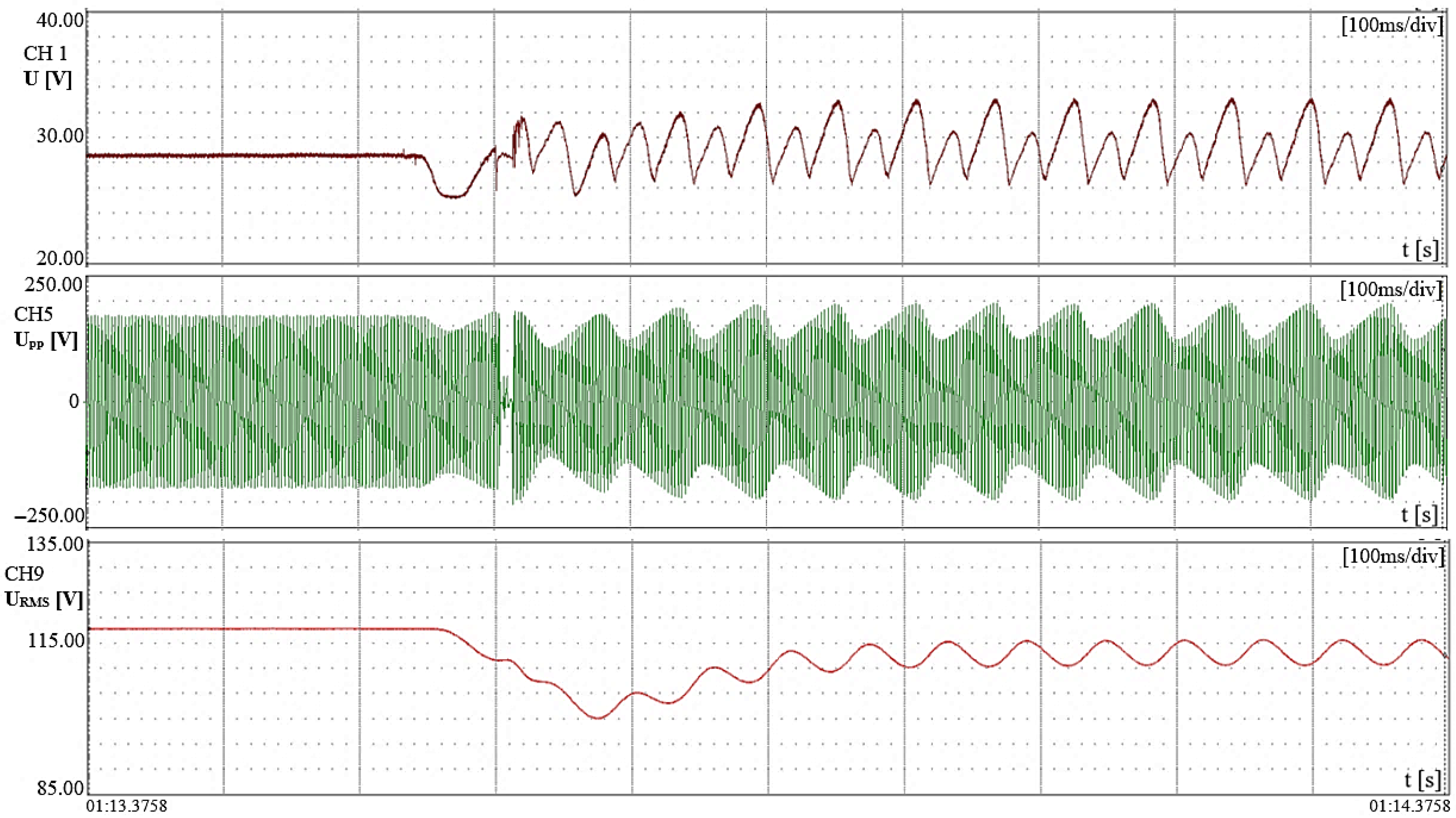
- a transient pulse (below 24 V)—during a sudden increase in load,
- (b)
- a surge pulse (above 29 V)—during a sudden decrease in load.
4. Materials and Methods
4.1. Commutator-Based DC Generators as Electrical Energy Sources for Public Utility Power Grids
- (a)
- the generator’s energy efficiency, especially under conditions of dynamic changes in its load level and the destruction of its commutator,
- (b)
- the process of thermal overload of the generator,
- (c)
- current overload of the excitation winding,
- (d)
- the speed of the automatic voltage regulation system supplied by it.
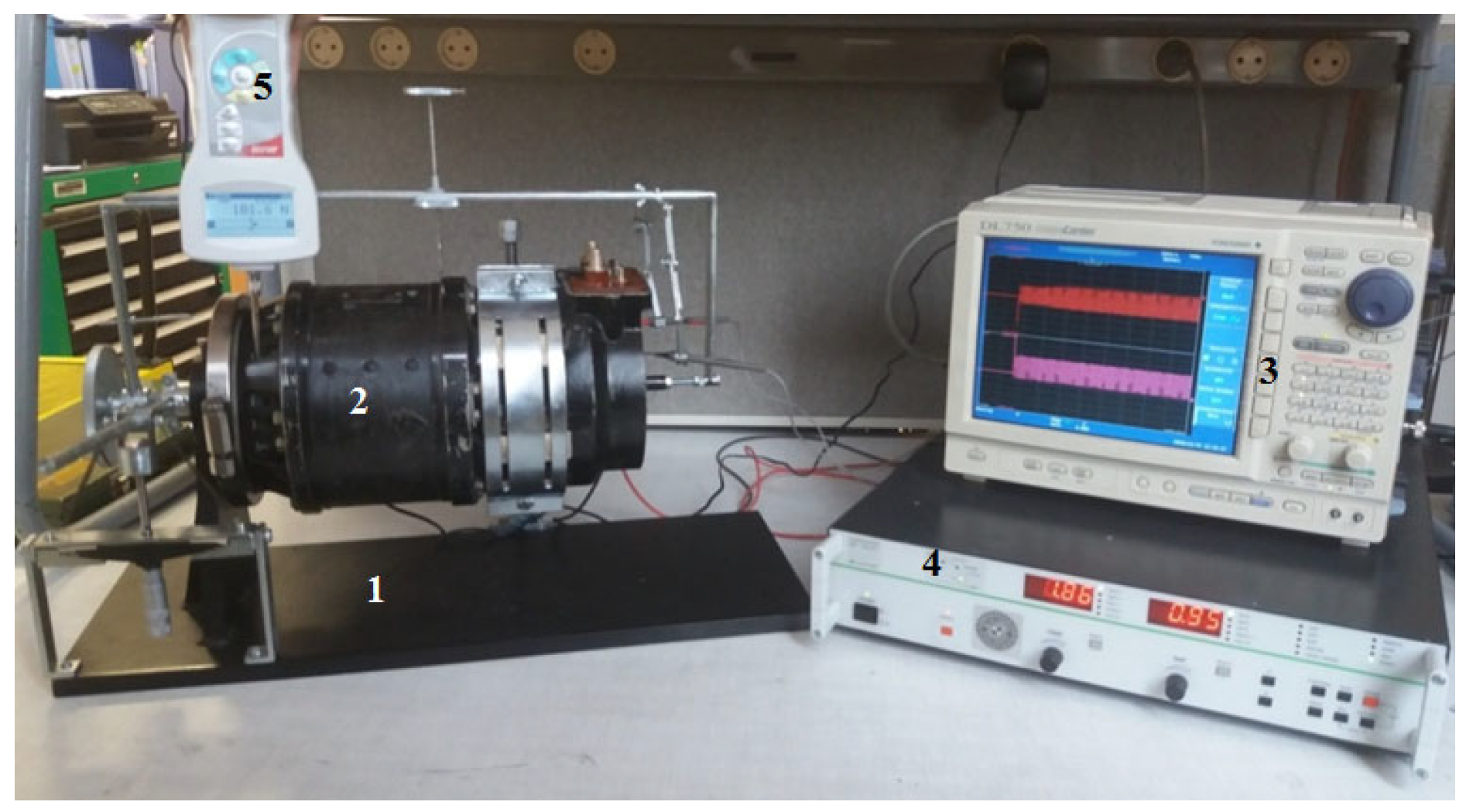
4.2. Measurement and Regulation of Commutator DC Generators in Terms of the Positioning of the Generator Brushes Relative to the Magnetically Neutral Zone
4.3. Shaping the Characteristics of a Commutator DC Generator
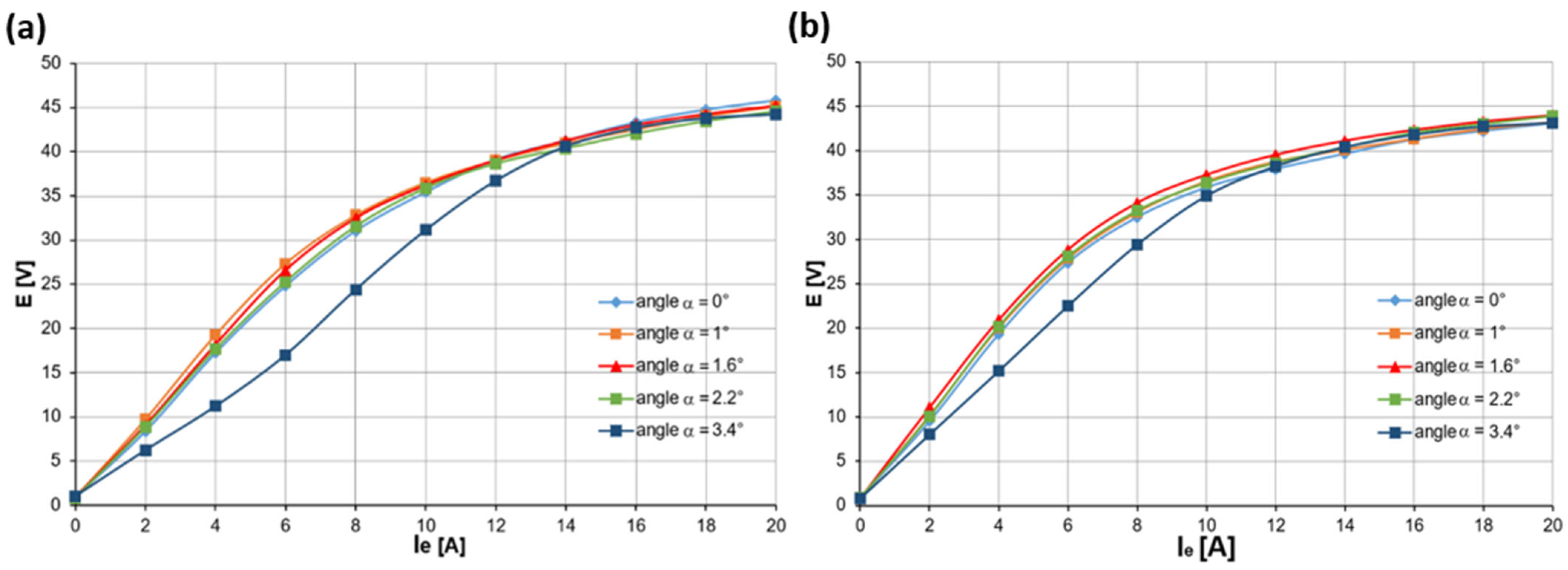
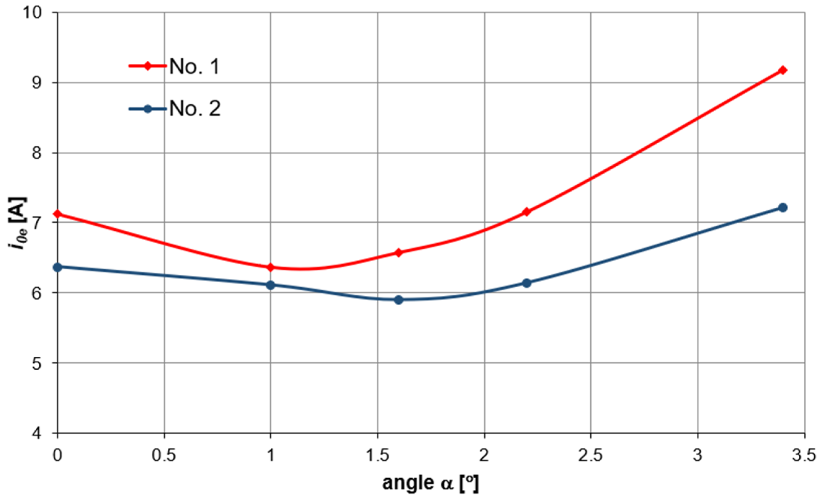
4.3.1. The Influence of the Brush Position Angle Relative to the Magnetically Neutral Zone on the Idle Operating State of the Generator
- (a)
- aging changes in the rotor magnetization characteristics—the rotor’s magnetic permeability characteristics become lower and flatter over time—these changes are directly proportional to the operating time and temperature,
- (b)
- reduced commutator diameter (due to periodic rewinding)—the brush shorts a larger number of rotor turns per unit of time,
- (c)
- increasing the effective air gap—due to increased clearances in the rotor assembly bearing.
4.3.2. The Influence of the Brush Position Angle Relative to the Magnetically Neutral Zone on the Generator’s Control Properties
- (a)
- for a generator with 0 h of operation on the primary winding, the transverse armature reaction flux Φq is compensated by the magnetic flux of the compensating winding Φkom, which is opposite in direction but equal in absolute value, in accordance with the requirements [33] for angle settings Φ in the range from 0.1° to 1.5°,
- (b)
- for a generator with a significant operating time (1677 h of operation on the primary winding), due to aging changes, the weakening transverse armature reaction flux Φq is overcompensated in the range from 0° to 1.0°—this flux is compensated by the magnetic flux of the compensating winding Φkom, which is opposite in direction but equal in absolute value, in accordance with the requirements [57] only for angle settings Φ in the range from 1.0° to 2.6°.
4.3.3. The Influence of the Brush Position Angle Relative to the Magnetically Neutral Zone on the Generator Properties in Transient States
5. Mathematical Model of a Commutator-Type DC Generator
5.1. Mathematical Model
5.2. Examples of Simulation Test Results
6. An Example of the Practical Use of Power Source Characteristics Shaping to Effectively Counteract the Aging Process of an Aircraft DC Power Grid
7. Conclusions
Author Contributions
Funding
Data Availability Statement
Conflicts of Interest
Abbreviations
| A/C | Aircraft |
| ASSL | Abnormal steady-state limits |
| DC | Direct Current |
| ESSL | Emergency steady-state limits |
| NSSL | Normal steady-state limits |
| CBA | commutator-brush assembly |
References
- Abu-Rub, H.; Malinowski, M.; Al-Haddad, K. (Eds.) Power Electronics for Renewable Energy Systems, Transportation, and Industrial Applications, 1st ed.; John Wiley & Sons Ltd.: Hoboken, NJ, USA, 2014. [Google Scholar]
- Gębura, A.; Setlak, L.; Tokarski, T.; Borowski, J. (Eds.) Lotnicze Urządzenia Elektryczne: Monografia; Wydawnictwo Instytutu Technicznego Wojsk Lotniczych: Warszawa, Poland, 2023; ISBN 978-83-61021-59-9. [Google Scholar]
- Brombach, J.; Lucken, A.; Nya, B.; Johannsen, M.; Schulz, D. Comparison of different electrical HVDC-architectures for aircraft application. In Electrical Systems for Aircraft, Railway and Ship Propulsion (ESARS); IEEE: Piscataway, NJ, USA, 2012; pp. 1–6. [Google Scholar]
- Sarlioglu, B.; Morris, C.T. More Electric Aircraft: Review, Challenges, and Opportunities for Commercial Transport Aircraft. IEEE Trans. Transp. Electrif. 2015, 1, 54–64. [Google Scholar] [CrossRef]
- Sciascera, C.; Giangrande, P.; Brunson, C.; Galea, M.; Gerada, C. Optimal design of an electro-mechanical actuator for aerospace application. In Proceedings of the Annual Conference of the IEEE Indus-Trial Electronics Society, Yokohama, Japan, 9–12 November 2015. [Google Scholar]
- Zhao, X.; Guerrero, J.M.; Wu, X. Review of Aircraft Electric Power Systems and Architectures. In Proceedings of the International Energy Conference (ENERGYCON), Cavtat, Croatia, 13–16 May 2014; IEEE: Piscataway, NJ, USA, 2014. [Google Scholar]
- NO-17-A206:2019; Wojskowe Statki Powietrzne—Naziemne Układy Zasilania Elektroenergetycznego. Podstawowe Parametry, Wymagania i Badania. MINISTRA OBRONY NARODOWE: Warsaw, Poland, 2019.
- MIL-STD-704F (W/Change-1); Department of Defense INTERFACE Standard: Aircraft Electric Power Characteristics. United States Department of Defense: Washington, DC, USA, 2016.
- Cur Krzysztof, Gołda Paweł, Jemielniak Mirosław, Sarnowski Witold: Analysis of selected problems of the operation of means of air transport. Aviat. Secur. Issues 2023, 4, 405–421. [CrossRef]
- Zieja, M. Prognozowanie Trwałości Wybranych Urządzeń Osprzętu Lotniczego w Aspekcie Procesów Starzenia. Ph.D. Thesis, Instytut Techniczny Wojsk Lotniczych, Warsaw, Poland, 2008. [Google Scholar]
- Gębura, A.; Radoń, T. Pulsacje napięcia wyjściowego jako źródło informacji diagnostycznych o komutatorowych prądnicach prądu stałego. Pr. Nauk. Inst. Tech. Wojsk Lotniczych 2013, 33, 57–74. [Google Scholar] [CrossRef]
- Wang, Y.; Nuzzo, S.; Zhang, H.; Zhao, W.; Gerada, C.; Galea, M. Challenges and opportunities for wound field synchronous generators in future more electric aircraft. IEEE Trans. Transp. Electrif. 2020, 6, 1466–1477. [Google Scholar] [CrossRef]
- Setlak, L.; Ruda, E. Review, analysis and simulation of advanced technology solutions in power electronics systems (PES) of more electric aircraft. World Acad. Sci. Eng. Technol. 2015, 9. [Google Scholar]
- Gębura, A.; Szelmanowski, A.; Jacyna-Gołda, I.; Gołda, P.; Kalbarczyk, M.; Tomaszewska, J. Concepts and Experiments on More Electric Aircraft Power Systems. Energies 2025, 18, 1653. [Google Scholar] [CrossRef]
- Aguida, M.E.; Che, Y.; Yang, J. Technological Advancements and Future Prospects of Electrical Power Systems for Sustainable More Electric Aircraft. Propuls. Power Res. 2024, 13, 475–486. [Google Scholar] [CrossRef]
- Samolot PZL-130 TC—II ORLIK. Opis Techniczny Część II Osprzęt; EADS PZL Warszawa-Okęcie S.A.: Warszawa, Poland, 2004. [Google Scholar]
- PZL-Świdnik, S.A. Śmigłowiec PZL W-3WA—Instrukcja Obsługi Technicznej; Wyd. PZL-Świdnik S.A.: Świdnik, Poland, 2012. [Google Scholar]
- Samolot M-28B/PT-GC „Skytruck” z awioniką Glass Cockpit. Album Schematów Elektrycznych Samolotu „M28B/PT” z Awioniką Glass Cockpit T2/2. Część 2. Osprzęt/Uzbrojenie; Nr PRG/Z/15/2010; PZL-Mielec: Mielec, Poland, 2010; Available online: https://pzlmielec.pl/ (accessed on 17 February 2025).
- CASA C-295M; C-295 Electrical System Description and Operation. MI-295-3-056-I. Construccions Aeronauticas S.A.: Madrid, Spain, 2012.
- Instrukcja Obsługi Śmigłowca SW-4; PZL Świdnik: Świdnik, Polonia, 2015.
- Petreski, D.; Iliev, A.; Trajanovska, E.; Gjurov, L.; Petrovski, A. Improved technical characteristics of the MI-8/17 in the Army of FYR Macedonia. Mil. Tech. Cour. 2018, 66, 122–142. [Google Scholar] [CrossRef]
- Lee, D.; Choi, D. Analysis of the reliability of a starter-generator using a dynamic Bayesian network. Reliab. Eng. Syst. Saf. 2020, 195, 106628. [Google Scholar] [CrossRef]
- Wawrzyński, W.; Zieja, M.; Tomaszewska, J.; Michalski, M. Reliability Assessment of Aircraft Commutators. Energies 2021, 14, 7404. [Google Scholar] [CrossRef]
- Zhuo, L.; Yang, D.; Sun, R.; Shi, D.; Zhou, J. Research on Ignition Starting Characteristics of Aeronautical Starter-Generator with Turbine Engine Based on Reduced Order Model. In Proceedings of the 2023 26th International Conference on Electrical Machines and Systems (ICEMS), Zhuhai, China, 5–8 November 2023. [Google Scholar] [CrossRef]
- ISO 1540:2006; Aerospace—Characteristics of Aircraft Electrical Systems. ISO Copyright Office: Cham, Switzerland, 2006.
- Filina, O.A.; Martyushev, N.V.; Malozyomov, B.V.; Tynchenko, V.S.; Kukartsev, V.A.; Bashmur, K.A.; Pavlov, P.P.; Panfilova, T.A. Increasing the Efficiency of Diagnostics in the Brush-Commutator Assembly of a Direct Current Electric Motor. Energie 2024, 17, 17. [Google Scholar] [CrossRef]
- Żurek, J.; Zieja, M. The aging-processes-based forecasting of service lives of selected items of air craft equipment. J. KONBiN 2008, 4, 287–305. Available online: http://worldcat.org/issn/189582814 (accessed on 2 March 2025).
- Dub, M.; Drlik, P. Modelling of aircraft DC generator voltage regulation In Proceedings of the MECHATRONIKA, 15th International Symposium, Prague, Czech Republic, 5–7 December 2012.
- Tokarski, T. Kształtowanie Charakterystyk Komutatorowej Prądnicy Prądu Stałego Statku Powietrznego. Ph.D. Thesis, 561/506 Instytut Techniczny Wojsk Lotniczych: Warszawa, Poland, 2023. [Google Scholar]
- Sun, R.; Peng, H.; Shi, D.; Huang, G. Research on Optimal Design of Commutation Performance of Starter-Generator Used in Aero-Engine. In Proceedings of the 2021 IEEE International Magnetic Conference (INTERMAG), Lyon, France, 26–30 April 2021. [Google Scholar] [CrossRef]
- Shantarenko, S.; Shantarenko, S.; Vaganov, A. Performance Control of the Commutator-and-brush Assembly of the Traction Motor. Transp. Res. Procedia 2021, 54, 854–861. [Google Scholar] [CrossRef]
- Sawa, K.; Isato, M.; Ueno, T.; Nakano, K. Commutation characteristics and brush wear of DC motor at high rotation speed. In Proceedings of the 2017 IEEE Holm Conference on Electrical Contacts, Denver, CO, USA, 10–13 September 2017. [Google Scholar] [CrossRef]
- Zhang, Q.; Ueno, T.; Morita, N. The new commutation theory to the optimization technique of the large dc machine commutation design. IEEJ Trans. Ind. Appl. 2011, 131, 1518–1521. [Google Scholar] [CrossRef]
- Tokarski, T.; Kalisiak, M. Układ do pomiaru położenia szczotek prądnicy prądu stałego względem strefy neutralnej. Opis patentowy PL 238723 B1 ogłoszono 27.09.2021 r. WUP 26/21. Available online: https://ewyszukiwarka.pue.uprp.gov.pl/search/pwp-details/P.430838 (accessed on 2 March 2025).
- Kozłowski, J. Laboratorium Elektrotechniki Teoretycznej; Wydawnictwo Politechniki Poznańskiej: Poznań, Poland, 1998. [Google Scholar]
- Wardach, M. Magnetic wedges influence of pulsation in electrical machine with permanent magnets. Przegląd Elektrotechniczny 2010, 86, 163–166. Available online: https://www.researchgate.net/publication/272143434_Magnetic_wedges_influence_of_pulsation_in_electrical_machine_with_permanent_magnets (accessed on 2 March 2025).
- Sołbut, A. Maszyny Elektryczne 2—Maszyny Prądu Stałego, Maszyny Synchroniczne; Oficyna Wyd. Politechniki Białostockiej: Białystok, Poland, 2019; ISBN 978-83-66391-10-9. [Google Scholar]
- Wasiluk, W. Poradnik Inżyniera Elektryka—Tom 2; Wydawnictwo Naukowo Ttechniczne: Warszawa, Poland, 2007; Available online: https://www.ksiegarnia-fachowa.pl/wiecej.php?id=ni-471 (accessed on 1 March 2025)ISBN 978-83-204-3292-3.
- Setlak, L.; Ruda, E. Współczesne rozwiązania technologiczne, analiza i symulacja wybranych komponentów architektury HVDC samolotów zgodnych z koncepcją MEA/AEA. Przegląd Elektrotechniczny 2017, 2. [Google Scholar] [CrossRef]
- Tokarski, T.; Michalak, S. The effect of the operation time of the aircraft power system on power quality in transient states. J. KONBiN 2024, 54, 47–64. [Google Scholar] [CrossRef]
- Tokarski, T. Evaluation of direct current electric power systems of the aircraft based on characteristics of a transient state. Diagnostyka 2019, 20, 81–91. [Google Scholar] [CrossRef]
- Leśniczak, A. i Inni: Badania i Ocena Stanu Technicznego Samolotu Su-22 M4 nr 30304 w Czasie Remontu Weryfikacyjnegosprawozdanie nr SP-147/31/2015; Instytut Techniczny Wojsk Lotniczych: Warszawa, Poland, 2016. [Google Scholar]
- Silnik 89—Opis techniczny; Dowództwo Wojsk Lotniczych: Poznań, Poland, 1988; Lot. 2560/86.
- Samolot Su-22M4—Aerodynamika Praktyczna; Dowództwo Wojsk Lotniczych: Poznań, Poland, 1987; DWL Lot. 2596/87.
- Tokarski, T.; Gębura, A. Analiza Możliwości Doprowadzenia Układu Zasilania Elektrycznego Prądu Stałego Samolotów Su-22 Do Samoregulacji Napięcia Zgodnie z Wymaganiami Normy Obronnej NO-15-A200: 2007 z Uwzględnieniem Wyników Badań Wykonanych w Czasie Remontu Weryfikacyjnego. Sprawozdanie Nr 177/OP/43/16—BT ITWL 8623/50; Instytut Techniczny Wojsk Lotniczych: Warszawa, Poland, 2016. [Google Scholar]
- Dzik, M. Bezpieczeństwo lotów w lotnictwie wojskowym—Czynniki i okoliczności wpływające na powstawanie wypadków I incydentów lotniczych. Obron.—Zesz. Nauk. Wydziału Zarządzania I Dowodzenia Akad. Obrony Nar. Nr 2013, 1, 73–91. [Google Scholar]
- Lewitowicz, J. Podstawy Eksploatacji Statków Powietrznych—Eksploatacyjne Problemy w Projektowaniu i Modernizacji Statków Powietrznych; Wydawnictwo Instytutu Technicznego Wojsk Lotniczych: Warszawa, Poland, 2012. [Google Scholar]
- Zadencki, R. Analiza Uszkodzeń Samolotów Wielozadaniowych F-16 Block 52+ Podczas ich Eksploatacji. Ph.D. Thesis, Politechnika Poznańska, Poznań, Poland, 2020. [Google Scholar]
- Glinka, T. Maszyny Elektryczne i Transformatory—Podstawy Teoretyczne, Eksploatacja i Diagnostyka; Instytut Napędów I Maszyn Elektrycznych Komel: Katowice, Poland, 2015. [Google Scholar]
- Hockmeyer, I.O. The generation and regulation of electric power in aircraft: A survey of design features of generators and their control. J. Inst. Electr. Eng.-Part II Power Eng. 1946, 93, 2. [Google Scholar] [CrossRef]
- Milewski, Z. Aerodynamika Konstrukcja i Systemy Statku Powietrznego; Wydawnictwo WAT: Warszawa, Poland, 2008; ISBN 978-83-89399-82-3. [Google Scholar]
- Leśniczak, A. i Inni: Kompleksowa Ocena Stanu Technicznego Samolotów Su-22 na Podstawie Wyników Badań i Weryfikacji Wykonanych w Procesie Remontu Weryfikacyjnego Oraz Opracowanie Zaleceń Profilaktycznych Do Eksploatacji Samolotów po Remoncie; BT ITWL 1830/I; Instytut Techniczny Wojsk Lotniczych: Warszawa, Poland, 2018. [Google Scholar]
- Lewitowicz, J.; Szelmanowski, A.; Gębura, A.; Pazur, A.; Franczuk, E.; Tokarski, T. Badanie zjawiska zniekształceń stref magnetycznie obojętnych w lotniczych komutatorowych prądnicach prądu stałego. Przegląd Elektrotechniczny 2019, 95, 78–81. [Google Scholar] [CrossRef]
- Tokarski, T.; Kalisiak, M. Stanowisko do badania i regulacji położenia szczotek komutatorowej prądnicy prądu stałego GS-12T 3s względem strefy neutralnej Wzór użytkowy W.128337. Numer prawa wyłącznego Ru.072444 ogłoszono 07.03.2022. Available online: https://uprp.gov.pl/pl/uslugi-online/e-wyszukiwarka (accessed on 1 March 2025).
- Bolkowski, S. Elektrotechnika. Wydawnictwo Szkolne i Pedagogiczne, S.A.: Warszawa, Poland,, 2005; ISBN 978-83-02. [Google Scholar]
- Jaworski, B.; Dietłaf, A.; Miłkowska, L.; Siergiejew, G. Kurs Fizyki. Elektryczność i Magnetyzm. Tom 2; PWN: Warszawa, Poland, 1984; ISBN 83-01-01265-X. [Google Scholar]
- Samolot S-32MK—Opis Techniczny i Eksploatacja Oddzielnych Przyrządów i Agregatów Osprzętu; Ministerstwo Obrony Narodowej—Dowództwo Wojsk Lotniczych: Poznań, Poland, 1976; Lot.1758/76.

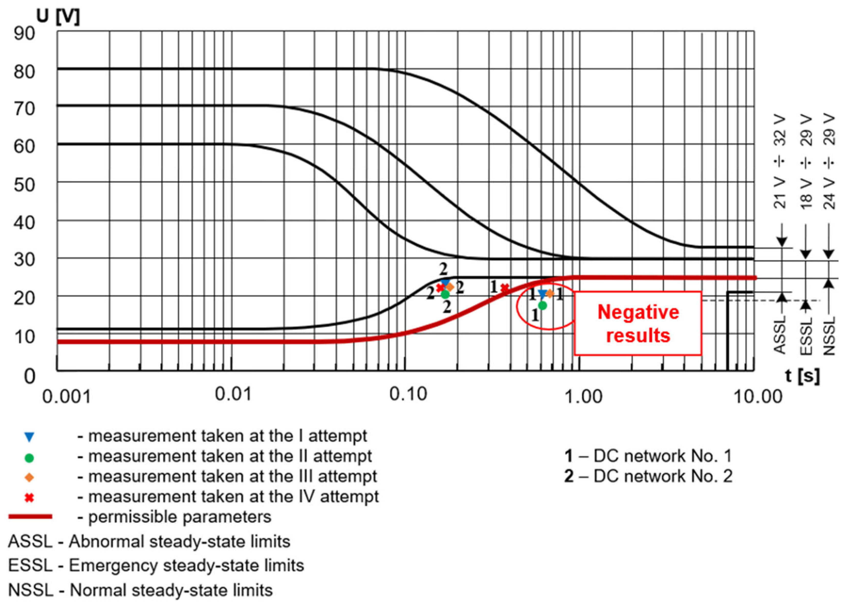





| No. | Number of the Tested DC Network | Number of Months of Operation on the A/C | |||||||
|---|---|---|---|---|---|---|---|---|---|
| I Test Initial State | II Test Condition After 31 Months of Operation | III Test Condition After 63 Months of Operation | IV Test Condition After 92 Months of Operation | ||||||
| Values of the Equivalent Pulse Parameters | |||||||||
| tz [ms] | Umin [V] | tz [ms] | Umin [V] | tz [ms] | Umin [V] | tz [ms] | Umin [V] | ||
| 1. | No. 1 | 10 | 21.6 | 39 | 18.89 | 29 | 19.89 | 40 | 21.54 |
| 8 | 23.3 | 76 | 21.74 | 164 | 22.29 | 202 | 22.71 | ||
| 2. | No. 2 | 24 | 21.6 | 62 | 19.23 | 28 | 19.73 | 114 | 21.75 |
| 20 | 23.1 | 192 | 20.45 | 315 | 21.98 | 305 | 21.48 | ||
| No. | Number of the Tested DC Network | Measurement Results in Subsequent Tests Su-22 | |||||||
|---|---|---|---|---|---|---|---|---|---|
| I Test | II Test | III Test | IV Test | ||||||
| Values of the Equivalent Pulse Parameters | |||||||||
| tz [ms] | Umin [V] | tz [ms] | Umin [V] | tz [ms] | Umin [V] | tz [ms] | Umin [V] | ||
| 1. | No. 1 | 605 | 20.51 | 159 | 19.82 | 650 | 20.03 | 37 | 20.01 |
| 20.92 | 450 | 20.82 | 21.06 | 352 | 21.77 | ||||
| 2. | No. 2 | 21 | 20.46 | 22 | 20.37 | 18 | 20.46 | 16 | 20.31 |
| 139 | 22.87 | 140 | 22.81 | 158 | 22.83 | 135 | 22.64 | ||
| No. | Excitation Current | The Angle α of the Brush Position Relative to the Neutral Zone of the Generator [°] | |||||||||
|---|---|---|---|---|---|---|---|---|---|---|---|
| 0 | 1.0 | 1.6 | 2.2 | 3.4 | |||||||
| The Value of Electromotive Force E/Generator Number | |||||||||||
| Ie [A] | Eo [V] | E1 [V] | E1.6 [V] | E2.2 [V] | E3.4 [V] | ||||||
| No. 1 | No. 2 | No. 1 | No. 2 | No. 1 | No. 2 | No. 1 | No. 2 | No. 1 | No. 2 | ||
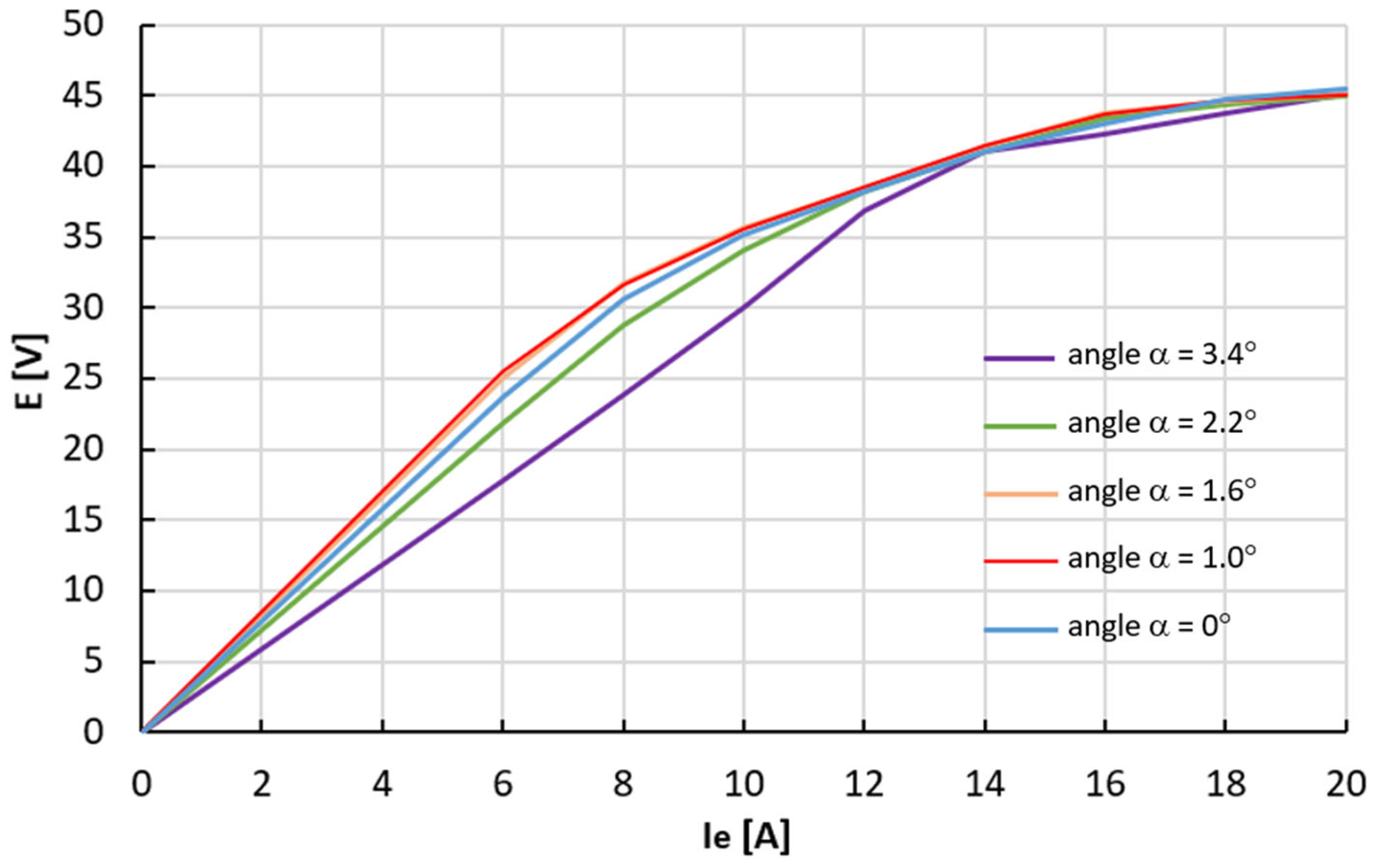
| 1. | 0 | 0.95 | 0.91 | 0.88 | 0.86 | 0.92 | 0.85 | 0.87 | 0.88 | 1.04 | 0.83 |
| 2. | 2 | 8.05 | 9.51 | 9.71 | 10.11 | 9.05 | 11.06 | 8.85 | 10.03 | 6.25 | 8.02 |
| 3. | 4 | 16.21 | 19.32 | 19.25 | 20.02 | 18.15 | 20.95 | 17.65 | 20.21 | 11.21 | 15.17 |
| 4. | 6 | 23.80 | 27.36 | 27.12 | 27.81 | 26.12 | 28.85 | 25.65 | 28.07 | 17.01 | 22.51 |
| 5. | 8 | 30.20 | 32.49 | 32.80 | 33.02 | 32.02 | 34.13 | 31.61 | 33.25 | 23.51 | 29.42 |
| 6. | 10 | 35.11 | 35.83 | 36.50 | 36.51 | 36.21 | 37.29 | 35.85 | 36.39 | 30.23 | 34.91 |
| 7. | 12 | 38.70 | 37.92 | 39.02 | 38.72 | 39.02 | 39.53 | 38.62 | 38.61 | 36.52 | 38.26 |
| 8. | 14 | 41.24 | 39.62 | 40.95 | 40.08 | 41.25 | 41.12 | 40.35 | 40.40 | 40.61 | 40.42 |
| 9. | 16 | 43.32 | 41.24 | 42.51 | 41.31 | 43.03 | 42.33 | 42.02 | 42.03 | 42.73 | 41.82 |
| 10. | 18 | 44.75 | 42.19 | 44.02 | 42.41 | 44.25 | 43.28 | 43.42 | 43.02 | 43.81 | 42.74 |
| 11. | 20 | 45.80 | 43.08 | 45.11 | 43.17 | 45.19 | 43.98 | 44.53 | 43.91 | 44.24 | 43.14 |
| No. | Generator GS-12T 3s | Generator Hours Since the Beginning of Operation on the A/C | The Value of the Electromotive Force on the Generator Armature at n = 4200 rpm | The Angle α of the Brush Position Relative to the Neutral Zone of the Generator [°] | ||||
|---|---|---|---|---|---|---|---|---|
| 0 | 1.0 | 1.6 | 2.2 | 3.4 | ||||
| Rated No-Load Excitation Current | ||||||||
| [hours] | E [V] | I0e [A] | ||||||
| 1. | No. 1 | 0 | 28.5 | 7.12 | 6.36 | 6.57 | 7.15 | 9.18 |
| 2. | No. 2 | 1677 | 6.37 | 6.11 | 5.90 | 6.14 | 7.21 | |
| No. | Generator Load Current Iload [A] | Angle α of the Brush Position Relative to the Neutral Zone [°] | |||||||||
|---|---|---|---|---|---|---|---|---|---|---|---|
| 0 | 1.0 | 1.6 | 2.2 | 3.4 | |||||||
| Average Value of Excitation Current Ie/Generator Number | |||||||||||
| Ie0 [A] | Ie1 [A] | Ie1.6 [A] | Ie2.2 [A] | Ie3.4 [A] | |||||||
| No. 1 | No. 2 | No. 1 | No. 2 | No. 1 | No. 2 | No. 1 | No. 2 | No. 1 | No. 2 | ||
| 1. | 0 | 2.60 | 2.60 | 2.59 | 2.60 | 2.60 | 2.59 | 2.59 | 2.57 | 2.60 | 2.57 |
| 2. | 50 | 2.75 | 2.52 | 2.74 | 2.61 | 2.94 | 2.71 | 2.96 | 2.69 | 3.05 | 2.97 |
| 3. | 100 | 2.87 | 2.41 | 2.91 | 2.63 | 3.27 | 2.75 | 3.38 | 2.78 | 3.55 | 3.34 |
| 4. | 150 | 2.95 | 2.34 | 3.07 | 2.80 | 3.58 | 2.85 | 3.77 | 2.89 | 4.0 | 3.63 |
| 5. | 200 | 2.98 | 2.37 | 3.25 | 2.85 | 3.78 | 3.05 | 4.15 | 3.04 | 4.43 | 4.05 |
| 6. | 250 | 3.06 | 2.40 | 3.43 | 2.88 | 4.07 | 3.27 | 4.53 | 3.30 | 4.79 | 4.50 |
| 7. | 300 | 3.05 | 2.42 | 3.70 | 2.92 | 4.22 | 3.39 | 4.80 | 3.45 | 5.02 | 4.78 |
| 8. | 350 | 3.04 | 2.34 | 3.91 | 2.93 | 4.40 | 3.62 | 5.12 | 3.72 | 5.39 | 4.98 |
| 9. | 400 | 3.03 | 2.27 | 4.05 | 3.01 | 4.52 | 3.82 | 5.37 | 3.90 | 5.78 | 5.38 |
| 10. | ΔIe = I400A − I0A | 0.46 | −0.33 | 1.46 | 0.41 | 1.92 | 1.23 | 2.78 | 1.33 | 3.18 | 2.81 |
| No. | Generator Speed [rpm] | Angle α of the Brush Position Relative to the Neutral Zone [°] | |||||||||
|---|---|---|---|---|---|---|---|---|---|---|---|
| 0 | 1.0 | 1.6 | 2.2 | 3.4 | |||||||
| Equivalent substitute Impulse Siz [Vms] /Generator Number | |||||||||||
| Siz0 [A] | Siz1 [A] | Siz1.6 [A] | Siz2.2 [A] | Siz3.4 [A] | |||||||
| No. 1 | No. 2 | No. 1 | No. 2 | No. 1 | No. 2 | No. 1 | No. 2 | No. 1 | No. 2 | ||
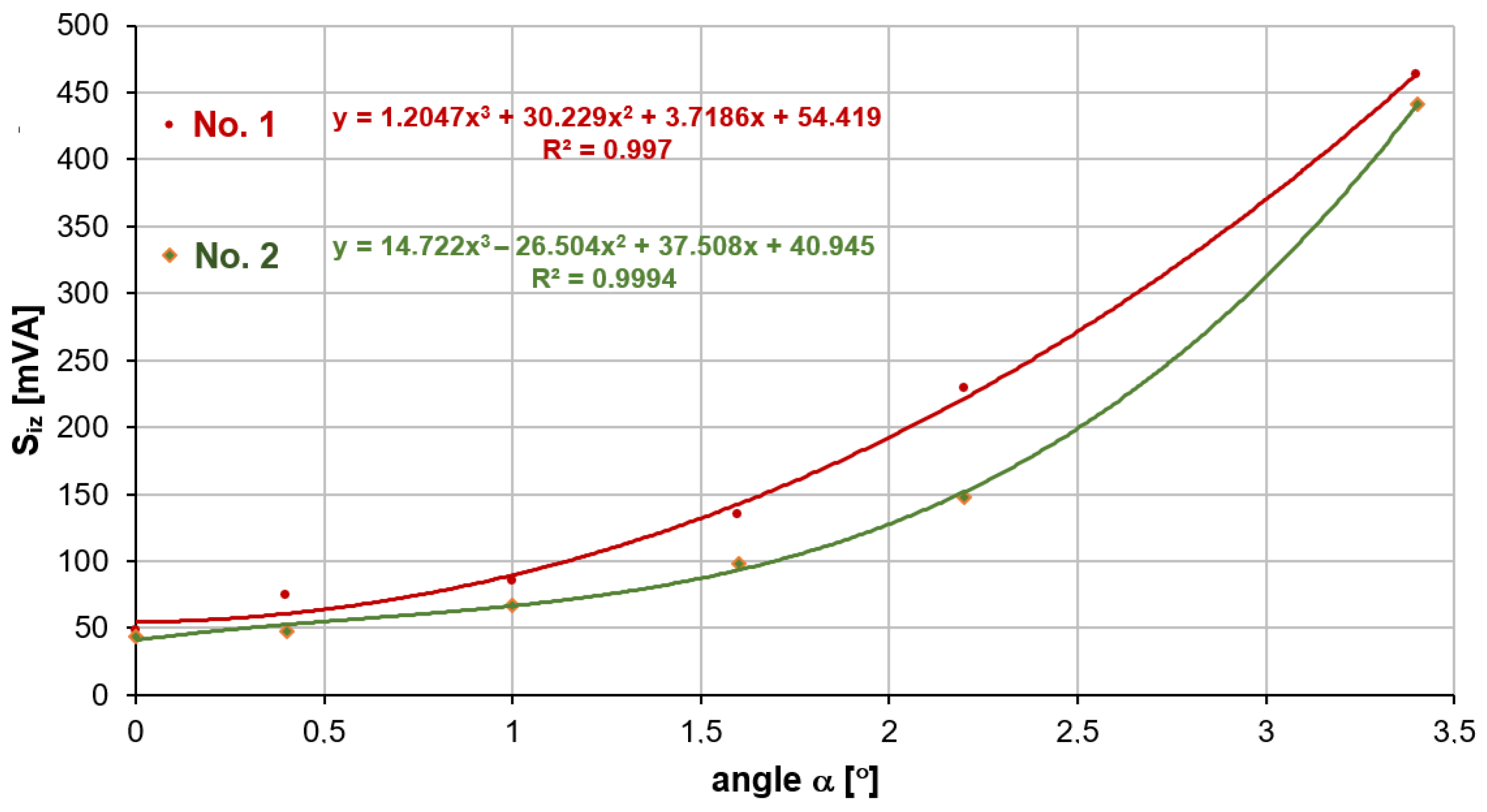
| 1. | 5050 | 58.6 | 43.4 | 84.6 | 67.1 | 134.5 | 98.5 | 229.2 | 148.1 | 462.8 | 441.2 |
| 2. | 6633 | 44.3 | 36.7 | 67.8 | 49.8 | 106.9 | 65.4 | 139.1 | 87.0 | 200.9 | 175.1 |
| 3. | 9000 | 41.2 | 32.5 | 62.7 | 43.9 | 87.2 | 54.2 | 112.7 | 79.7 | 158.0 | 167.7 |
| No. | Generator Number GS-12T 3s | Operation Time of Generators on the Su-22 A/C | The Value of the α Angle in the Generator (Before Adjustment) During the First Engine Test | The Value of the α Angle in the Generator (After Adjustment) During the Second Engine Test |
|---|---|---|---|---|
| [hours] | [°] | [°] | ||
| 1. | No. 3 | 1744 | 3.1 | 1.6 |
| 2. | No. 4 | 1168 | 2.6 | 1.4 |
| No. | Network Power Source | Transient Parameters of the Su-22 A/C Power Grid | |||||
|---|---|---|---|---|---|---|---|
| I Test Before Adjusting the α Angle | II Test After Adjusting the α Angle | ||||||
| tz [ms] | Umin [V] | Siz [Vms] | tz [ms] | Umin [V] | Siz [Vms] | ||
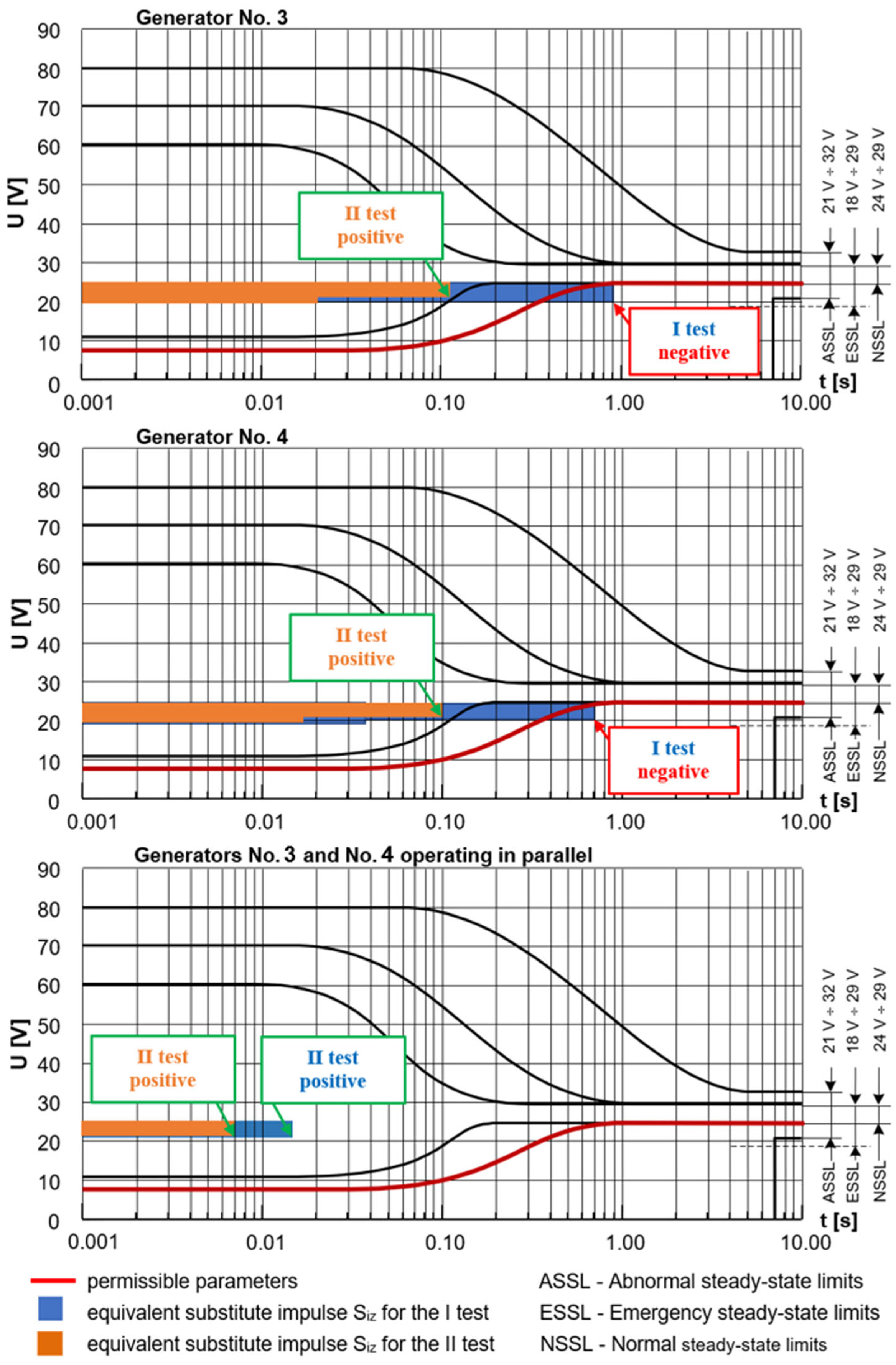
| 1. | Generator No. 3 | 115 | 20.26 | 430.1 | 20 | 20.16 | 76.8 |
| 895 | 20.17 | 3427.9 | 108 | 22.52 | 159.8 | ||
| 2. | Generator No. 4 | 36 | 19.86 | 149.0 | 16 | 20.50 | 56.0 |
| 702 | 21.34 | 1867.3 | 95 | 22.87 | 107.4 | ||
| 3. | Generators No. 1 and No. 2 operating in parallel | 13 | 20.97 | 39.4 | 7 | 21.07 | 21.5 |
Disclaimer/Publisher’s Note: The statements, opinions and data contained in all publications are solely those of the individual author(s) and contributor(s) and not of MDPI and/or the editor(s). MDPI and/or the editor(s) disclaim responsibility for any injury to people or property resulting from any ideas, methods, instructions or products referred to in the content. |
© 2025 by the authors. Licensee MDPI, Basel, Switzerland. This article is an open access article distributed under the terms and conditions of the Creative Commons Attribution (CC BY) license (https://creativecommons.org/licenses/by/4.0/).
Share and Cite
Tokarski, T.; Michalak, S.; Gajewski, T. Counteracting the Aging Process of the Aircraft’s DC Power Grid in the Context of Shaping the Characteristics of the Power Source. Energies 2025, 18, 5132. https://doi.org/10.3390/en18195132
Tokarski T, Michalak S, Gajewski T. Counteracting the Aging Process of the Aircraft’s DC Power Grid in the Context of Shaping the Characteristics of the Power Source. Energies. 2025; 18(19):5132. https://doi.org/10.3390/en18195132
Chicago/Turabian StyleTokarski, Tomasz, Sławomir Michalak, and Tomasz Gajewski. 2025. "Counteracting the Aging Process of the Aircraft’s DC Power Grid in the Context of Shaping the Characteristics of the Power Source" Energies 18, no. 19: 5132. https://doi.org/10.3390/en18195132
APA StyleTokarski, T., Michalak, S., & Gajewski, T. (2025). Counteracting the Aging Process of the Aircraft’s DC Power Grid in the Context of Shaping the Characteristics of the Power Source. Energies, 18(19), 5132. https://doi.org/10.3390/en18195132


