Article

Advancing Sustainable Propulsion Solutions for Maritime Applications: Numerical and Experimental Assessments of a Methanol HT-PEMFC System

1
Department of Engineering, University of Naples Parthenope, 80143 Naples, Italy
2
Department of Industrial Engineering (DII), University of Naples “Federico II”, 80125 Naples, Italy
3
Department of Industrial Engineering (DII), University of Salerno, 84084 Fisciano, Italy
*
Author to whom correspondence should be addressed.
Energies 2025, 18(19), 5119; https://doi.org/10.3390/en18195119
Submission received: 22 July 2025 / Revised: 12 September 2025 / Accepted: 17 September 2025 / Published: 26 September 2025

Abstract

The interest in analyzing alternative fuels and new propulsion technologies for shipping decarbonization is growing rapidly. This paper aims to evaluate the performance of high-temperature polymeric exchange membrane fuel cells (HT-PEMFCs) fed by reformed methanol and their potential application as a propulsion system for vessels. The proposed system is intended to be installed on board a 10 m long ship, designed for commercial use in the marine area of Capri Island. Numerical and experimental analyses were performed to estimate the system’s performance, and a feasibility assessment was carried out to verify its real applicability on board the reference case study. From the numerical perspective, a CFD model of the ship hull, as well as a thermochemical model of the propulsion system, was developed. From the experimental point of view, the system behavior was tested by means of a dedicated test bench. The results of the numerical models allowed for the sizing of the propulsion system and the calculation of the fuel consumption. In particular, to satisfy the ship’s power demand, two 5 kW HT-PEMFCs were needed, with a total fuel consumption of 12.7 kg over a typical daily cruise, with a methanol consumption of 1.88 kg/h during cruising at 7 knots. The feasibility analysis highlighted that the propulsion system fits the vessel’s requirements, both in terms of volume and weight.

1. Introduction

The shipping sector is enduring a transformation as it strives to align with the ambitious goals set by the Paris Agreement [1,2]. This international accord, aimed at limiting the global temperature increase to well below 2 °C—while striving to cap it at 1.5—has catalyzed significant changes across industries worldwide, including maritime transport, which accounts for about 4% of global greenhouse gas emissions. These demands are driving innovation, fostering the adoption of alternative fuels, and encouraging the development of new technologies [3,4]. Different solutions can be evaluated for achieving carbon neutrality in the shipping sector [5,6].
Among these alternative solutions, methanol has emerged as a promising fuel for the shipping sector, offering a unique combination of environmental and operational advantages. As a liquid fuel, methanol is straightforward to store and handle, relying on existing infrastructure with minimal modifications. Its clean-burning properties significantly reduce emissions of sulfur oxides (SOXs) and particulate matter, aligning with stricter global environmental regulations [7]. Moreover, methanol can be synthesized from renewable sources, such as biomass or captured carbon dioxide, making it a viable candidate for achieving net-zero emissions in the whole life cycle [8].
Methanol’s versatility allows it to be used across a range of vessel types, from large ocean-going ships to smaller ones. Methanol-powered engines can be either retrofitted or newly designed for both spark [9] and compression ignition, providing greater flexibility during the transition [10,11]. On the other hand, electric passenger ships further exemplify the maritime industry’s shift towards sustainability, incorporating innovations in design, efficiency, and eco-friendliness. Companies worldwide are developing electric vessels that reduce emissions and operating costs while offering quiet and comfortable alternatives to traditional diesel-powered ferries or passenger ships. In this context, the transition towards the electrical propulsion based on fuel cell technology represents a key solution for pursuing decarbonization in shipping [12].
Low-temperature fuel cells require operating exclusively on pure hydrogen, which poses significant challenges in terms of storage due to the weight and volume of the hydrogen storage tanks. On the other hand, high-temperature fuel cells can utilize a range of hydrogen carriers, such as methanol, offering greater flexibility in fuel supply [13]. However, high-temperature fuel cells, such as Solid Oxide Fuel Cells (SOFCs), are less flexible and are primarily suitable for stationary applications [14,15]. In this context, High-Temperature Proton Exchange Membrane Fuel Cells (HT-PEMFCs) are a promising technology, since they combine the operational flexibility of low-temperature cells with the ability to operate at higher temperatures (120–200 °C), enabling them to be fueled with reformed fuels (a higher CO content), such as methanol.
From this perspective, HT PEMFCs can play a significant role in this transition. Their performance and near-silent operation make them ideal for both main propulsion and onboard power generation, especially in environmentally sensitive areas where noise and emissions are tightly regulated and where complete electrification of the ship is not feasible due to the high energy demand of its mission profile.

State-of-Art and Study Contribution

HT-PEMFCs are gaining attention in the maritime industry as a viable solution for reducing greenhouse gas emissions and meeting stricter environmental regulations. Through an onboard reforming process, these systems convert methanol into hydrogen, which is then used to generate electricity via fuel cells, offering a cleaner alternative to conventional marine propulsion solutions. The integration of reformed methanol with HT-PEMFC technology offers a highly effective solution to comply with decarbonization standards in the maritime sector. The usage of methanol as fuel and HT-PEMFCs as a propulsion system is widely exploited in the technical literature [10,16,17,18,19,20,21,22], but their integration is still not widely explored, as proved by the few studies that rely on the usage of methanol-based HT-PEMFCs. Russo et al. [23] investigated a small-scale methanol-based HT-PEMFC system for naval applications. The analyzed 1 kW system was based on the adoption of a methanol-reforming reactor fed by methanol, water, and air. The outlet stream was directly fed to an HT-PEMFC system for the generation of electrical power. The authors demonstrated that the system was fully self-sustaining from the energetic point of view, since the heat required for vaporization and pre-heating can be fully recovered from the reaction products and FC dissipation. Additionally, the authors also performed a preliminary sizing of the storage tank, catalytic reactor, and FC system and suggested that safe, efficient, and convenient on-board implementation is possible.
In the Pa-X-ell, part of the e4ships project [24], a 90 kW methanol-fueled (HT-PEMFC) system with a reformer was analyzed, to be installed on the MS Mariella passenger vessel as an auxiliary power unit, in parallel to its conventional energy supply. Specifically, the aim of the project was to formulate a concept for a decentralized energy grid and energy storage, and to develop and configure subsystems, as well as test them under conditions that closely simulate their future operating environment in a decentralized network.
Freudenberg e-Power Systems [25] developed an innovative approach for using methanol in shipping applications. This combined highly efficient fuel reforming technology with long-life HT-PEMFCs in a modular, scalable system unit. The hydrogen produced via steam reforming was used in the fuel cells to produce the electrical energy needed for both propulsion and the ship’s electrical system. The heat required for the reformer was obtained directly from the waste heat of the fuel cells. All the system components (reformer and control electronics, as well as all components for media supply) were located in a prefabricated, modular unit in order to facilitate the installation on board. The safety concept of this innovative system architecture received “Type Approval” from the classification society, RINA. This confirmed the safety of the system and its conformity with maritime standards and regulations.
Blue World Technologies [26] introduced an HT-PEMFC system tailored for maritime applications, providing a green alternative to conventional engines with a focus on developing modular systems ranging up to 2 MW for ship propulsion.
Based on this limited background, it is evident that there is a gap in the technical literature, as also shown in Table 1, related to the assessment of the performance and the feasibility of installing the methanol-based HT-PEMFC system on board ships. Therefore, the novelty of this paper is in its assessment of the performance of the proposed system and in verifying its potential applications on board an operating ship. In particular, the system under study is a 5 kW ADVENT SMR HT-PEMFCs [27] to be installed on board a 10 m long ship.

2. Materials and Methods

The present study is devoted to evaluating the energy performance and the feasibility of installing a methanol-based HT-PEMFC on board a ship. Figure 1 illustrates the methodology workflow followed in this study.
Firstly, the reference ship was characterized by means of CFD modeling aimed at defining the ship’s power requirement according to the identified hull. Then, the power system, consisting of reformed methanol-based HT-PEMFCs selected as the propulsion technology, was tested in a dedicated test bench and modeled by means of a thermochemical code. Then, the modeling results, validated by the experimental data, were used to estimate the system’s performance in its whole operating range. Finally, the feasibility of installing the system on board the reference ship was assessed.

2.1. Vessel Characterization

The feasibility assessment was performed for a specific case study related to the selected vessel, which is a pleasure ship, approximately 10 m in length, and intended for commercial use. This study addresses the need for commercial operators to access protected marine areas by using vessels equipped with sustainable and environmentally compatible propulsion solutions.

2.1.1. Hull Design and Modeling

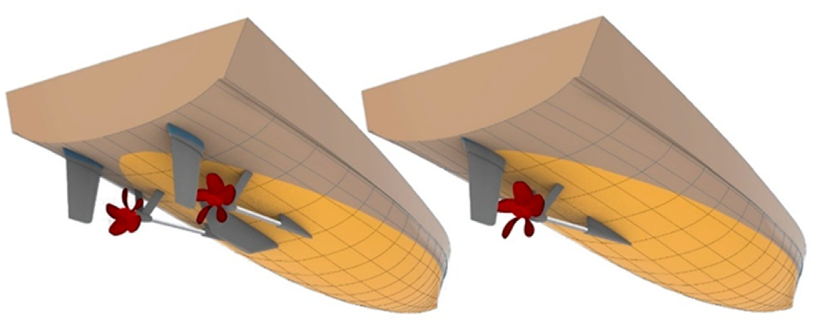
In order to characterize the ship hull, a Computational Fluid Dynamics (CFDs) analysis was carried out to accurately estimate the power requirements at various speeds, which are essential for the correct sizing of the propulsion system. CFD analysis is critical as it provides detailed insight into the hydrodynamic behavior of the hull, allowing for a more precise prediction of the resistance forces acting on it. The hull design, optimized for low-speed mission profiles, provides scalability and operational flexibility and is conceived to support both single and twin-screw propeller systems, making it adaptable to various configurations and sizes (Figure 2).
The CFD simulations were carried out at full scale, based on a reference hull with a waterline length of 23.33 m, which was previously tested during the design phase of a ship described in ref. [28]. The modeling results, in terms of the residual resistance, a portion of total hydrodynamic resistance (not related to viscous friction but to wave-making effects), are summarized in Table 2. The residual resistance coefficient (CR) solely depends on the Froude number (FN), making it the most suitable parameter for scaling hull resistance at different hull lengths. The results refer to the twin-screw configuration, which enhances both the maneuverability and the redundancy of the propulsion system.
To estimate the brake power (PB) needed for sizing the propulsive system, the Froude method is used by applying the ITTC 1957 (International Towing Tank Conference) guidelines [29]. These guidelines establish standardized equations and procedures to accurately interpret test results and extrapolate them to a different scale of the ship. The brake power (PB) is calculated as:
P B =   0.5   C T ρ   S V S 3 η g
where S is the wetted surface area, V S is the ship speed, C T is the total resistance coefficient, ρ is water density (typically 1025 kg/m3 for seawater), and η g   is the global efficiency of the propulsive system, assumed equal to 0.5, as suggested in ref. [28].
According to the ITTC 1957 standard, the frictional resistance coefficient Cf is calculated using the following equation:
C f = 0.075 ( log 10 R e 2 ) 2
where Re is the Reynolds number.
The residual resistance coefficient Cr is calculated as follows:
C r = C T C f
By applying these equations for the reference ship [28], the characteristics of a 10 m ship were estimated (Table 3) by a scaling-down approach.
The results of the scaling-down approach are summarized in Table 4.
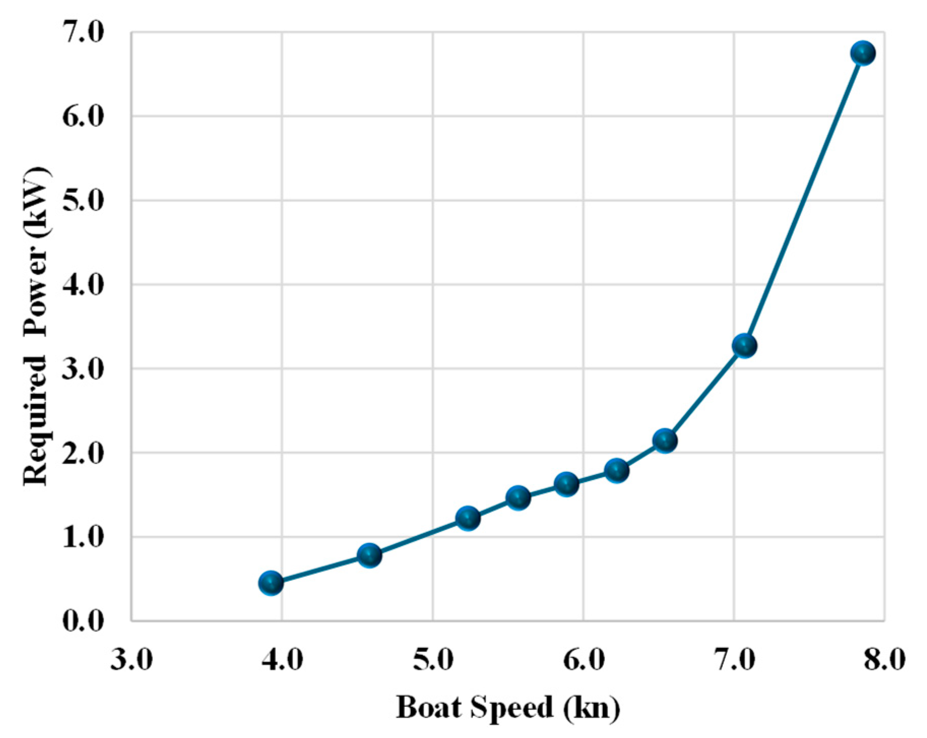
Figure 3 illustrates the brake power vs. the ship speed trend; it can be noticed that the zone with a higher efficiency is at moderate speeds (4–6 knots), where the power-to-speed ratio is more favorable. As a matter of fact, beyond 7 knots, the ship experiences a steep increase in required power without a proportional gain in speed. This is typical for displacement hulls, where hydrodynamic resistance increases rapidly as the vessel approaches higher Froude numbers (higher speeds).

2.1.2. Vessel Mission Profile

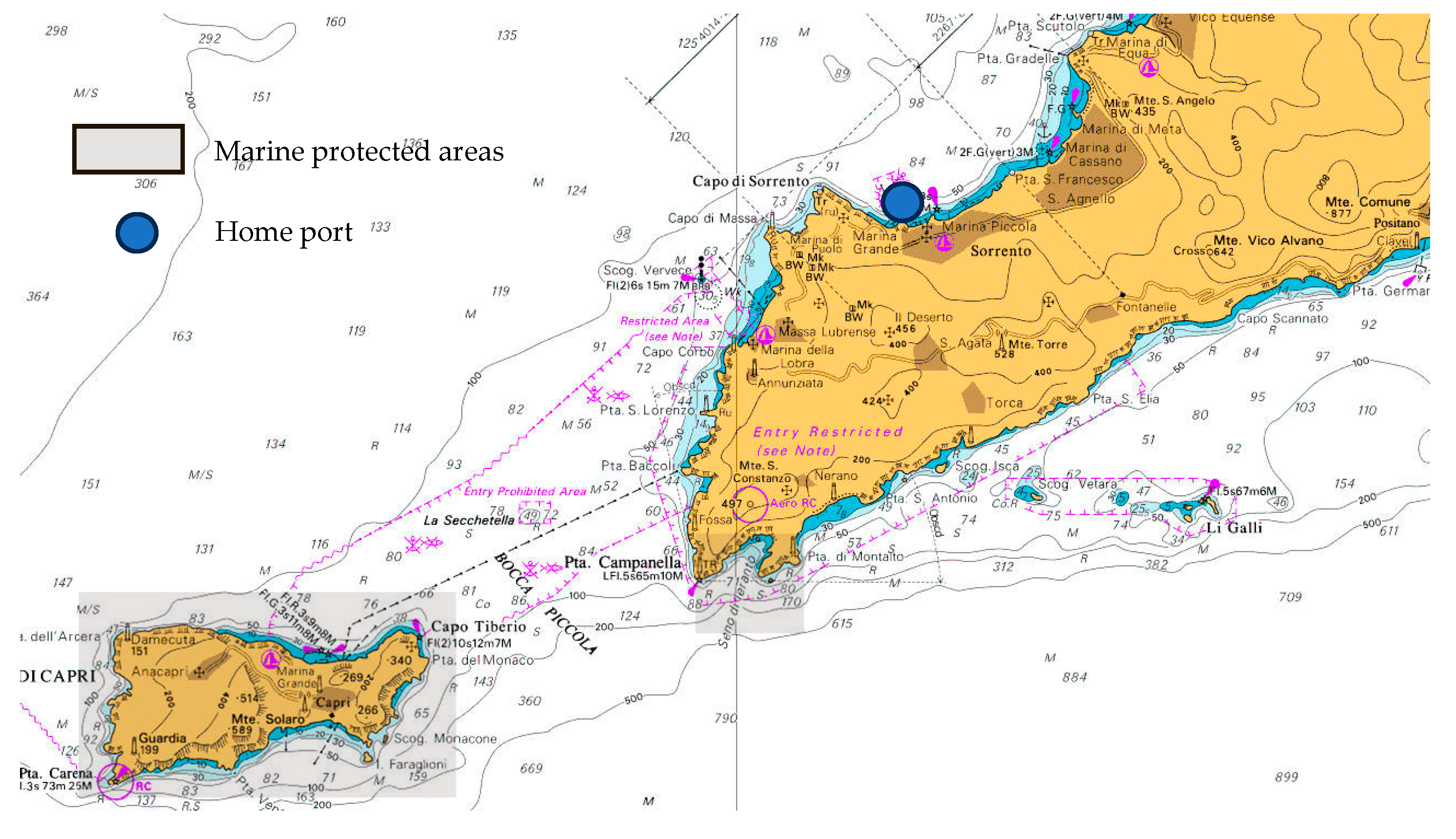
The hull described above is designed for potential commercial use in the marine area of Capri Island (Figure 4). Its typical use involves daily rental routes around Capri. Departures may take place from the coastline, and passengers may embark directly in Capri, which could soon become a designated marine protected area, requiring zero-emission or low-impact navigation solutions [30].
In this scenario, the use of an efficient hull, optimized for low-speed operations, enables the integration of a propulsion system that meets environmental requirements.
The proposed operational plan includes the following phases:
Leg 1: Approach to Capri: The initial leg towards Capri is powered by active fuel cells, which not only supply power to the propulsion system but also may recharge the battery (about 7 nm).
Leg 2: Around Capri at Low Speed: The vessel navigates around the island at approximately 4.5 knots (about 9 nm).
Leg 3: Return to Land: The return leg to port mirrors the same speed as the approach to Capri until the next entry into the P.ta Campanella protected marine area (about 1 nm).
Leg 4: Protected Marine Area Navigation: The vessel operates at zero emissions within the protected area (about 1 nm).
Leg 5: Return to Port: After completing the protected area navigation, the vessel returns to its home port (about 7 nm).
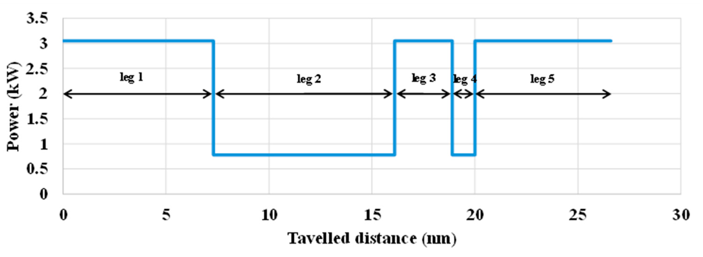
A diagram of the complete route in terms of power demand is shown in Figure 5, with selected speeds of 7 knots for transit and 4.5 knots for navigation within the protected zero-emission area.

2.2. Propulsion System Characterization: HT-PEMFC System

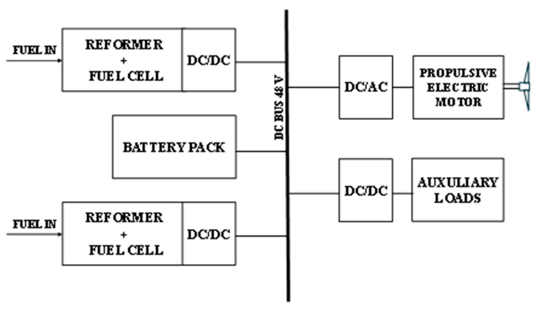
The propulsion system to be installed onboard the ship selected as the case study is presented in Figure 6.
The propulsion system is composed of the following:
  • Reformed Methanol Fuel Cell Systems: The HT-PEMFCs are powered by syngas coming from a reformed mixture of methanol and water. The system under study, made by ADVENT A/S, was tested by the University Federico II at the CNR-STEMS laboratories in Naples, showing a nominal power output of 5 kW from the fuel cells themselves and a maximum deliverable power of 4 kW.
  • Battery Pack: The lithium-ion battery pack operates as an energy buffer and allows compensation for the limited dynamic response of the fuel cells, providing propulsion power when the fuel cells cannot meet peak demand or in areas where only the battery pack is allowed as a power source [31].
  • Electric Propulsion Motor with Drive: The electric motor and drive system provide propulsion power to the propeller from the fuel cells and battery electric power [32].
  • Central 48 V DC Power Bus: A central bus operating at 48 V powers both the propulsion motors and auxiliary electrical loads of the ship. For the auxiliary loads, a DC/DC converter is used to reduce the voltage to 24 V.
This configuration allows the ship to operate efficiently in both hybrid and full-electric mode, according to the mission profile. Two stacks were installed to provide higher brake power at higher speeds (if needed) and to face increased resistance due to waves and hull fouling, as well as to provide redundancy to the system. Regarding the reformed methanol-based fuel cells, their description is provided in the following paragraph, while the battery considered for the simulation analyses is commercially available, with the characteristics listed in Table 5.

2.2.1. HT-PEMFC Testing Activities

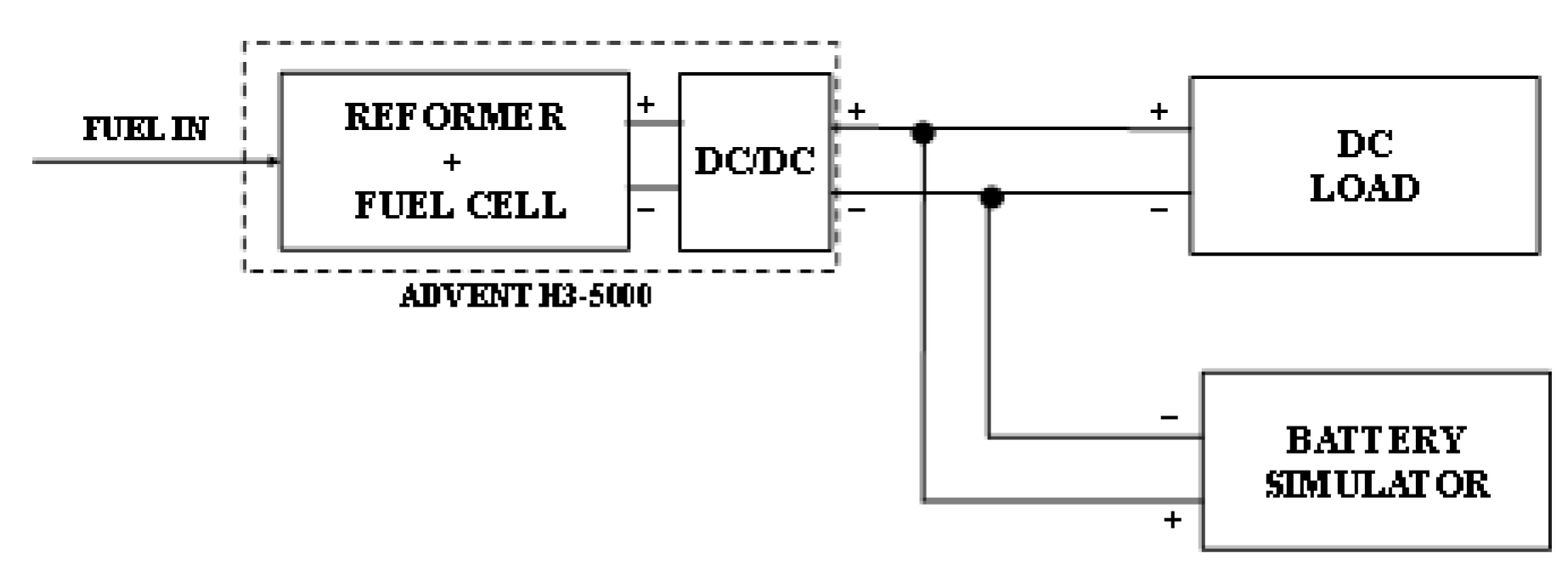
To perform the experimental characterization of the selected HT-PEMFC, a laboratory 1:1 scale test-bench, based on a Hardware-In-the-Loop (HIL) system, was set up. The main scheme of the testing facility is shown in Figure 7, where a complete powertrain was tested, including the battery pack, the FC system, and a load simulator, which can reproduce the behavior of the propulsion motors.
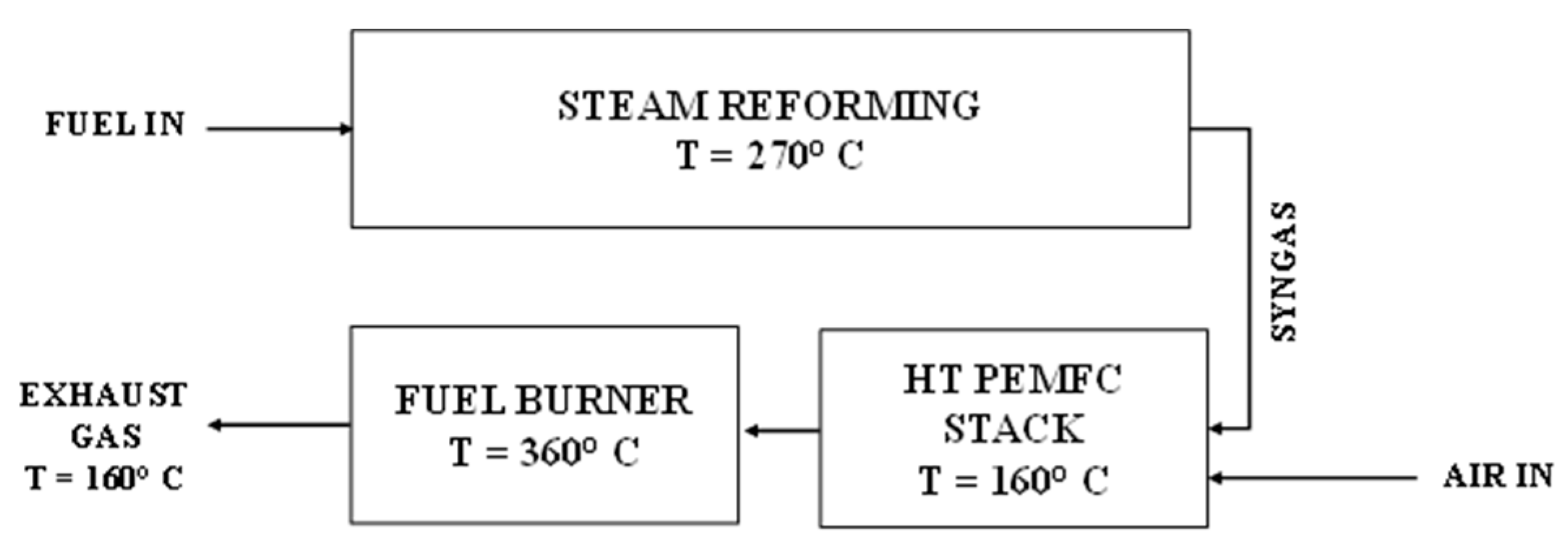
Specifically, the FC under analysis is a 5 kW reformed methanol fuel cell system provided by Advent Technologies (Aalborg, Denmark). The FC system is housed in a sealed metallic box (dimensions: 742 × 483 × 267) containing all the subsystems: the methanol reformer reactor, the HT-PEMFC stack, the catalytic burner reactor, and all the required heat exchangers and Balance of Plant (BoP) necessary for operation (Figure 8). This system utilizes thermal oil to transfer heat. The reformer employs a CuZn-based reforming catalyst, while the catalytic burner uses the anode waste gas from the fuel cells to provide heat for the catalytic reforming process. The burner is positioned in close proximity to the reformer.
The HT-PEM module is equipped with a DC/DC power converter that allows the system to work at higher voltage, operating within a range from 250 V to 420 V. This DC/DC power converter supports various control modes, enabling the HT-PEM module to function as a battery charger. Additionally, the DC/DC converter operates in bidirectional mode, allowing the battery pack to be used during the module start-up phase to warm up the system. All data related to the HT-PEMFC system under testing are reported in Table 6.
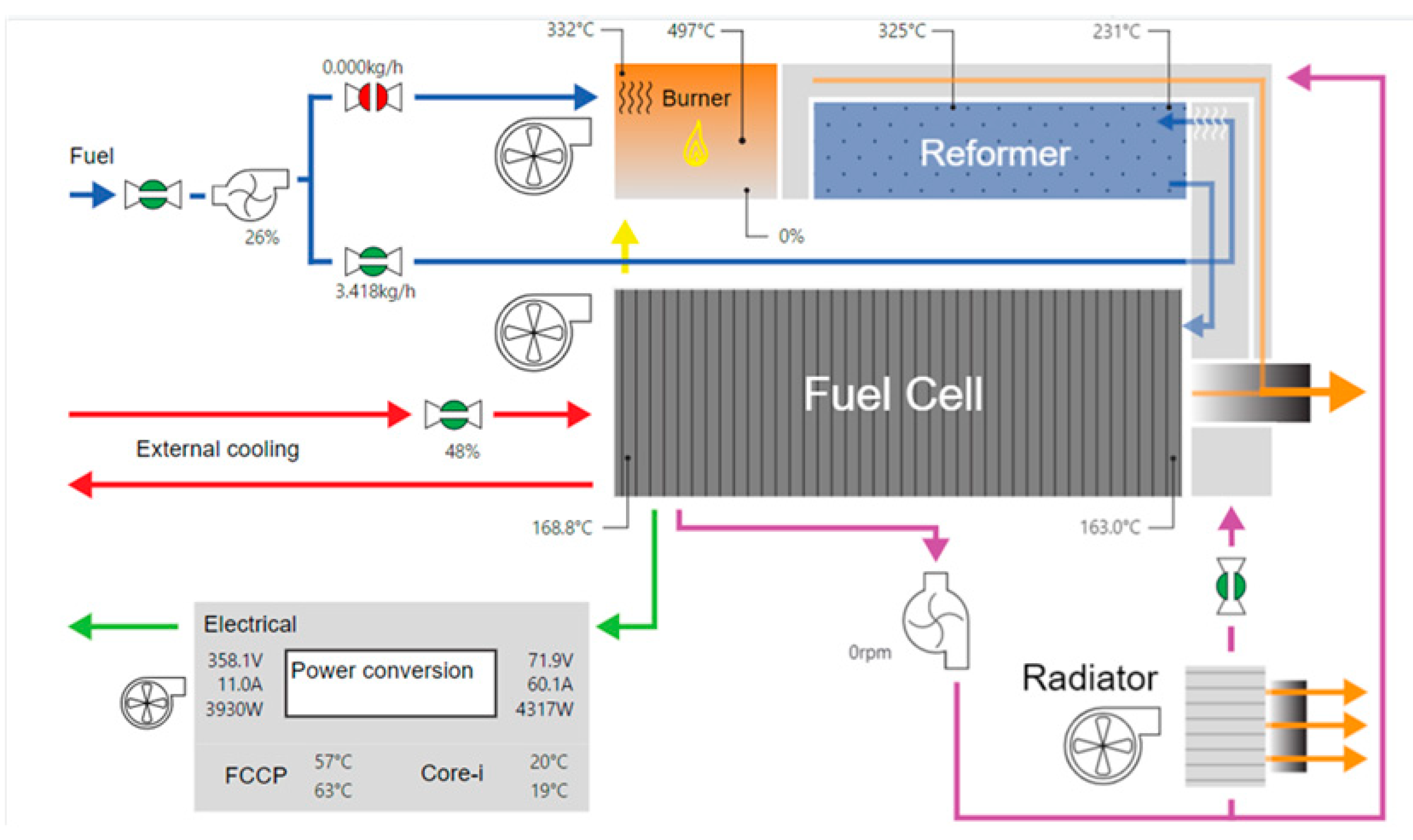
The loads were simulated using an electronic DC load, which is controlled in the range from 0 to 240 A, via analog voltage signals. The battery pack was simulated using a Battery Simulator (BS), which is a 54 kW bidirectional AC/DC power converter. This converter can be controlled to mimic the behavior of a variety of battery packs based on parameters such as number of cells, state of charge (SoC), and internal cell resistance. As for the FC module, it was monitored and controlled via a web server (Figure 9).
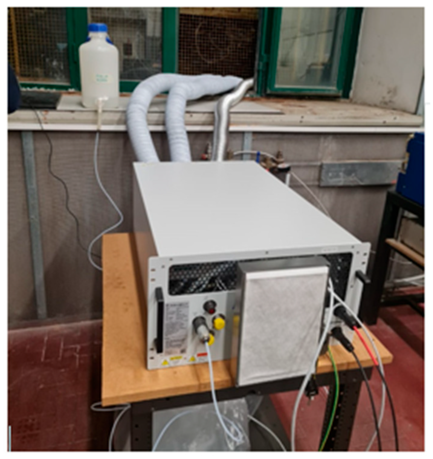
The monitoring software presents a synoptic scheme (Figure 9) that displays thermodynamic and electrical parameter values at various measurement points in the system. These parameters are also externally accessible using the SNMP communication protocol. The control software enables the selection of different charging modes and the adjustment of the charging power. A picture of the system testing is illustrated in Figure 10.
The fuel was composed of a mixture of methanol and deionized water (60/40 vol %), while for the cathode side, a built-in blower provided the required air for the cell reactions and burner reactions.
The experimental campaign lasted two months, during which the system was tested on nine separate occasions. These tests were designed to evaluate the system under different operating conditions by varying the output current of the fuel cells. The operating points were obtained by adjusting the cells’ output power through the dedicated control web server. Further long-term performance studies on the system are required, as issues originating from the reforming process (e.g., carbon monoxide (CO) and sulfur compounds) can lead to cell degradation and cannot be assessed. The literature clearly highlights that cell durability is strongly influenced by such contaminants, with variations that can be worsened under harsh environments, such as the marine context, where vibration, humidity, and saline air are present [35,36].
Nevertheless, destructive endurance testing was not carried out in this study. This decision was motivated both by the need to preserve the integrity of the system and by the fact that the commercial unit tested was already certified for a durability of 5000 operating hours, which is considered sufficient for light-duty applications, such as small commercial boats operating predominantly during the summer season.
Start-Up Phase
As soon as the system starts, the battery pack provides energy to an internal resistance for system preheating. After a few minutes of operation, with energy consumption of about 0.5 kWh, the catalytic burner reactor starts to use methanol to heat the reformer reactor up to about 270 °C and the HT-PEM stack to an average temperature of 160 °C. The whole process takes around 40 min.
Response to Load Variations
A study was conducted to analyze how the HT-PEMFC system behaves under varying load conditions. Initial tests focused on examining the system output current response to sudden step changes in the current reference signal (Figure 11).
Figure 9 illustrates that the system takes approximately 160 s to stabilize after a current increase from 4 A to 10 A. The observed power output exhibits a transient response ranging between 9.28 and 10.24 W/s. On the other hand, when the current decreases, the system response is faster, with a power transient of 19.2 to 20.26 W/s to reach a new steady level. The slower response to the current increase is due to fuel starvation (potentially leading to CO poisoning) when the hydrogen supply rate to the fuel cells is insufficient to meet the demand of a load change because of a slower response of the reformer and gas flow dynamics compared to the load variation. On the other hand, during a sudden stop or reduced load, the hydrogen produced for the fuel cells is redirected to the burner, which can result in elevated burner temperatures.
To mitigate these limitations in transient operation, the HT-PEMFC system was integrated with a battery pack, by using the battery simulator described in the previous section (cfr. Figure 6). Specifically, a 40 Ah battery pack consisting of 90 Lithium–Nickel–Manganese–Cobalt (Li-NMC) cells connected in series with a state of charge (SoC) of 40% was set. It is worth noting that the Li-NMC was selected because of its high energy density, which makes it suitable for mobile applications (e.g., battery electric vehicles).
Energy Management
To ensure the system operates effectively even outside the constraints outlined in the mission profile, a straightforward energy management strategy is implemented. Although the system can undergo further optimization, an initial approach assumes the fuel cell systems operate primarily as a battery charger.
According to this strategy, after completing its start-up phase, the fuel cells begin charging the battery until it reaches a user-defined maximum state of charge (SoC). Once this maximum SoC is achieved, the fuel cells are automatically set to a “zero-load” mode, delivering only the minimum power required to keep their internal systems active without supplying or drawing power from the powertrain. When the battery’s SoC drops to a minimum threshold, the fuel cells automatically restart charging the battery at a predefined power level, also set by the user. In this specific case study, the operational constraints are defined as follows:
SoCmax: 0.90
SoCmin: 0.40
Charging Power: Corresponds to a point of high efficiency in the fuel cells.
This strategy leverages the fuel cells at their highest efficiency point while maintaining a relatively narrow SoC range, which helps extend the battery’s lifespan. A too narrow SoC range would otherwise reduce the cell module life span due to multiple and frequent load changes. Additionally, setting a relatively high SoCmin ensures greater safety in terms of stored energy, allowing for an emergency return to port if necessary.
Thermal Management
Heat recovery from the fuel cell cooling system is important for increasing the efficiency of the overall fuel cell system, particularly in HT-PEMFCs integrated with a steam reforming unit devoted to hydrogen production from fossil fuels. HT-PEMFC stacks require a definition of effective thermal management strategies that can adjust the temperature within PEMFCs according to the design condition and to thermal power utilization in the combined heat and power configuration [37]. In the analyzed HT-PEMFC system [38], heat transfer is achieved through the use of a thermal oil loop. The system employs two independent oil circuits: one linking the burner with the reformer, and the other connecting the fuel cells with the evaporator. The separation of the two loops is necessary due to the different temperature levels involved, approximately 160 °C in the fuel cell circuit and around 260 °C in the burner circuit [38]. In the first circuit, the burner conveys its hot exhaust gases to a heat exchanger, where the thermal oil is heated before being circulated to the reformer. The second circuit, operating at about 160 °C, is dedicated to removing excess heat from the fuel cell stack. This recovered heat is subsequently used to vaporize the methanol–water fuel mixture prior to its introduction into the reformer.

2.3. HT-PEMFC System Model Development

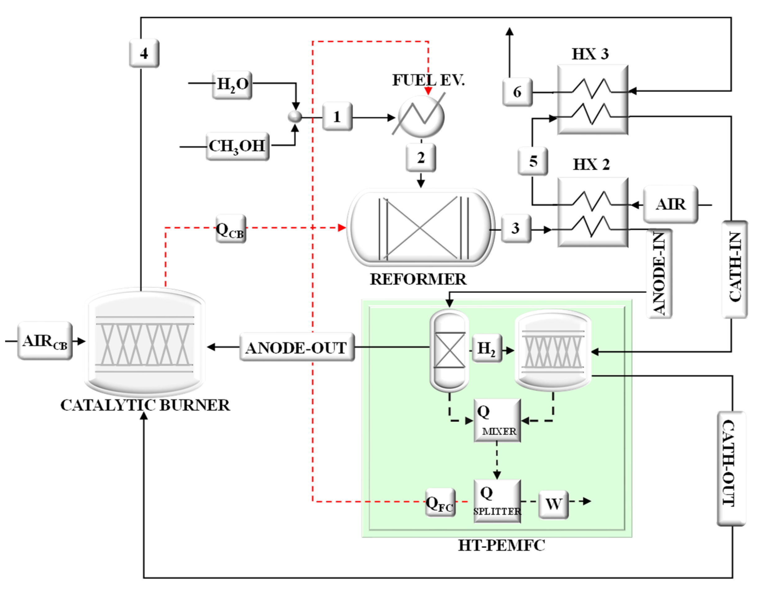
The methanol-fed HT-PEMFC system was modelled in the Aspen Plus™ 11 environment. The model was developed using a modular framework, in which a Hierarchy block is used to connect the PEMFC model to the BoP one. Figure 12 depicts the system flowsheet realized by considering the architecture of the 5 kW system developed by Advent Technologies.
This system is designed to operate with a mixture of methanol and water (stream#1, 60% and 40% by volume, respectively), which is first vaporized in the Fuel Evaporator (FUEL EV) by exploiting the available heat from the fuel cells (QFC) and then (stream#2) processed in a steam reforming unit to produce a reformate gas (stream#3). The reformate gas is subsequently cooled by transferring heat to the air in Heat Exchanger 2 (HX2) before entering the anode side of the HT-PEMFCs (stream#ANODE-IN), with a reduced CO content of approximately 3%. Meanwhile, the air exiting HX2 (stream#4) is further heated in Heat Exchanger 3 (HX3) before being supplied to the cathode side (stream#CATHODE-IN) of the HT-PEMFCs. A catalytic burner is employed to provide the necessary heat to sustain the reforming reaction (QFC).
A detailed description of each plant submodel is reported in the following sub-sections.

2.3.1. Heat Exchangers

The system architecture includes three different heat exchangers, varying in terms of both feeding streams and operating conditions. The HX1 is a gas–liquid heat exchanger, in which the methanol–water mixture (stream#1) is vaporized by means of the hot off-gas (stream#6) from the catalytic burner, before entering the reforming unit (stream#2). On the other hand, the HX2 is a gas–air heat exchanger, used for preheating the ambient air (stored @20 °C and @1 bar) and also for cooling the reformate gas (stream#3) from the reformer down to the operating conditions of the PEM-HT (160 °C). Finally, the HX3 (gas-air heat exchanger) is used for reheating the air (stream#4) up to the inlet temperature of the fuel cell stack.
For all the considered counter-current heat exchangers, the following set of equations is implemented:
Q = m ˙ c o l d · H c o l d = m ˙ h o t · H h o t = U · A · L M T D
where m ˙ (kg/s) represents the mass flow rate, H (kJ/kg) indicates the difference in terms of enthalpy, U (kW/m2K) is the heat transfer coefficient, A (m2) is the heat exchange area, and LMTD is the log-mean temperature difference, calculated as follows:
L M T D = T 1 T 2 log T 1 T 2
where T 1 and T 2 are the temperature differences between fluids in sections 1 and 2 of each heat exchanger, calculated, respectively, as T 1 = T h i n T c o u t and T 2 = T h o u t T c i n .
Finally, the number of thermal units is defined for counterflow exchangers in the following equation:
N T U = 1 1 C R ln 1 ε C R 1 ε
where C R represents the Heat Capacity Ratio, that is the ratio between the heat capacity rates of the two fluids in the heat exchanger, and ε indicates the effectiveness of the heat exchanger, expressed as the ratio of the actual heat transfer to the maximum possible heat transfer in the heat exchanger.
The HeatX component in the Aspen 11 Library is used for modeling the plant heat exchangers. It allows for simplified or detailed rating calculations for most types of four-stream heat exchangers.

2.3.2. Reformer

The reformer unit allows for obtaining from the methanol–water mixture a synthetic gas with a high hydrogen concentration through the following reactions taking place in the reactor, which refer to the reforming reaction, the decomposition reaction, and the water gas shift reaction, respectively:
C H 3 O H + H 2 O C O 2 + 3 H 2
C H 3 O H C O + 2 H 2
C O + H 2 O C O 2 + H 2
The reformer is modelled by using the RGibbs unit operator block, based on the Gibbs free energy minimization to calculate the equilibrium that does not require specified reaction stoichiometry. The total Gibbs free energy of the reaction system is:
E G i b b s t = i = 1 N n i · μ i
where   n i   is the number of moles of species i, and μ i is their chemical potential. In this equation, the constraint is to find the values of n i , which minimize the objective function E G i b b s t .
The proper method usually implemented for the minimization of the Gibbs free energy problem is the Lagrange multipliers. The constraint of this problem is the elemental balance, expressed as follows [39]:
i = 1 N n i · a i , j = A j         j = 1 , 2 , , k
where a i , j represents the number of atoms of the j element in a mole of the i   species. A j represents the total number of atoms of the j element in the reaction mixture. The Lagrange function (L) is:
L = E G i b b s t j = 1 k λ j i = 1 N n i · a i , j A j
where λ j is the Lagrange multiplier.
With the aim of finding the extremum point, the partial derivatives of Equation (13) are set equal to zero, as follows:
L n i = 0
Here, a set of non-linear equations is obtained, which can be solved by means of an iteration technique.

2.3.3. Catalytic Burner

This component is used to realize the combustion of the anode off-gases by using the cathode off-gases as the oxidant. The thermal power available in the exhaust gases is used, firstly, for providing the needed heat in the steam reformer (dashed red line in Figure 12). Moreover, the exhaust gases allow for the heating of the air entering the cathode side (in the HX2 and HX3) and also for heating the methanol–water mixture in the HX1. The RStoic component available in Aspen Library is used for simulating the Catalytic Burner (CB), which is a reactor in which the stoichiometry is known. The following combustion reactions are implemented in the component model:
H 2 + 1 2 O 2 H 2 O
2 C H 3 O H + 3 O 2 2 C O 2 + 4 H 2 O
C O + 1 2 O 2 C O 2
With respect to these reactions (hydrogen oxidation, methanol combustion, and carbon monoxide oxidation), the reactant gases are completely converted.

2.3.4. Proton Exchange Membrane Fuel Cell

The HT-PEMFC stack is modeled by discretizing each module by using a Hierarchy block. In this block, different components are integrated with each other to simulate both the anode and the cathode side, and, therefore, the entire fuel cell operation.
The anode is modelled as a separator unit in which the reactant hydrogen is split from the unreactant gases (methanol, water, CO2, and CO) or PURGE, and is supplied to the Rstoich (stoichiometric reactor) that is used to model the cathode. In the cathode, the oxygen reacts with hydrogen, producing water according to the following reaction:
H 2 + 1 2 O 2 H 2 O
Moreover, to solve the energy balance in the HT-PEMFC system, two specific block calculators are used: the Thermal Mixer block (QMIXER) and the Thermal Splitter block (QFSPLIT).
The Thermal Mixer block is used to carry out the energy balance, considering the sensible enthalpy changes of the feeding streams at the anode and the cathode sides and the heat of electrochemical reactions. The Thermal Splitter block (QFSPLIT), instead, is used to separate the output energy flux, in terms of work (W, the electrical power) and heat (Q, the thermal power).
Since Aspen Plus allows defining the thermochemistry but not the electrochemistry of the simulated system, the HT-PEMFC electrical performances (current, voltage, and electric power) are estimated using a Fortran block calculator. In particular, the cell voltage (V) is calculated by implementing in the Fortran block the empirical equation proposed by Kim et al. [40], which is widely used in the literature to model HT-PEMFC behavior. The specific implementation method and integration within the simulation environment follow the approach described in [41]. The empirical equation is:
V c e l l = V 0 b · ln J R · J m · e x p ( n · J )
V S t a c k = V c e l l · N c e l l
where V 0 (V) is the reversible cell potential, J is the current density (A/cm2), b (V/dec) is the Tafel slope, R (Ωcm2) is the ohmic resistance, and m (V) and n (cm/A) are parameters that account for the mass transport overpotential. These coefficients can be calculated by applying a regression technique to the polarization curve provided by the manufacturer. The stack voltage ( V S t a c k ) can be obtained by multiplying the cell voltage by the number of cells in the stack (120 cells).
The current (I) is calculated by applying Faraday’s equation, as follows:
I = z · n H 2 · F
where z is the number of electrons, n is the molar flow rate of the reactant hydrogen (mol/s), and F is the Faraday constant (96,485 C/mol).
Consequently, the electric power generated by the stack is calculated as:
W E L = V · I
The amount of hydrogen consumed in the anode depends on the assumed fuel utilization factor U F , which is defined as:
U F = m ˙ H 2 , c o n s u m e d m ˙ H 2 , i n
where m ˙ H 2 , c o n s u m e d   (kg/s) and m ˙ H 2 , i n (kg/s) represent the hydrogen consumed in the anode and the hydrogen amount feeding the cells, respectively.
As previously mentioned, the methanol-based HT-PEMFCs were modelled assuming, as reference, the 5 kW system developed by Advent Technologies, whose nominal data are reported in Table 6.

3. Results

The results presented in this section refer to (i) experimental testing, (ii) model identification and validation, (iii) the simulated energy and mass balance of the system, and (iv) the feasibility assessment, evaluating the possibility of installing such technology on board the reference ship.

3.1. Experimental Results

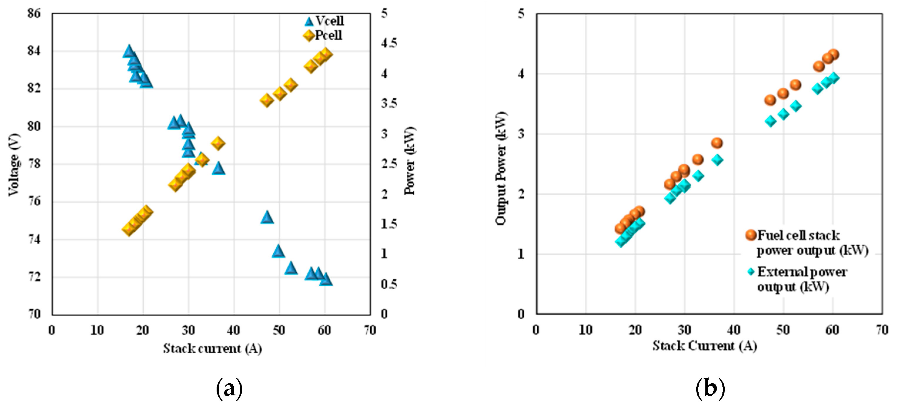
In this paragraph, the experimental data measured on the stack (120 cells; 165 cm2 cell active area) operation in a steady state are presented. In Figure 13a, the polarization curve of the cells and the power curve measured before using the DC/DC converter are reported, while the comparison between the output power from the cells and the delivered power to the bus can be seen in Figure 13b. It must be noted in Figure 13b that the difference in power (about 0.5 kWe) between the stack power output and the external power output is due to the internal parasitic load related to the presence of the air blowers, fuel pump, electronic circuits, and power converter.
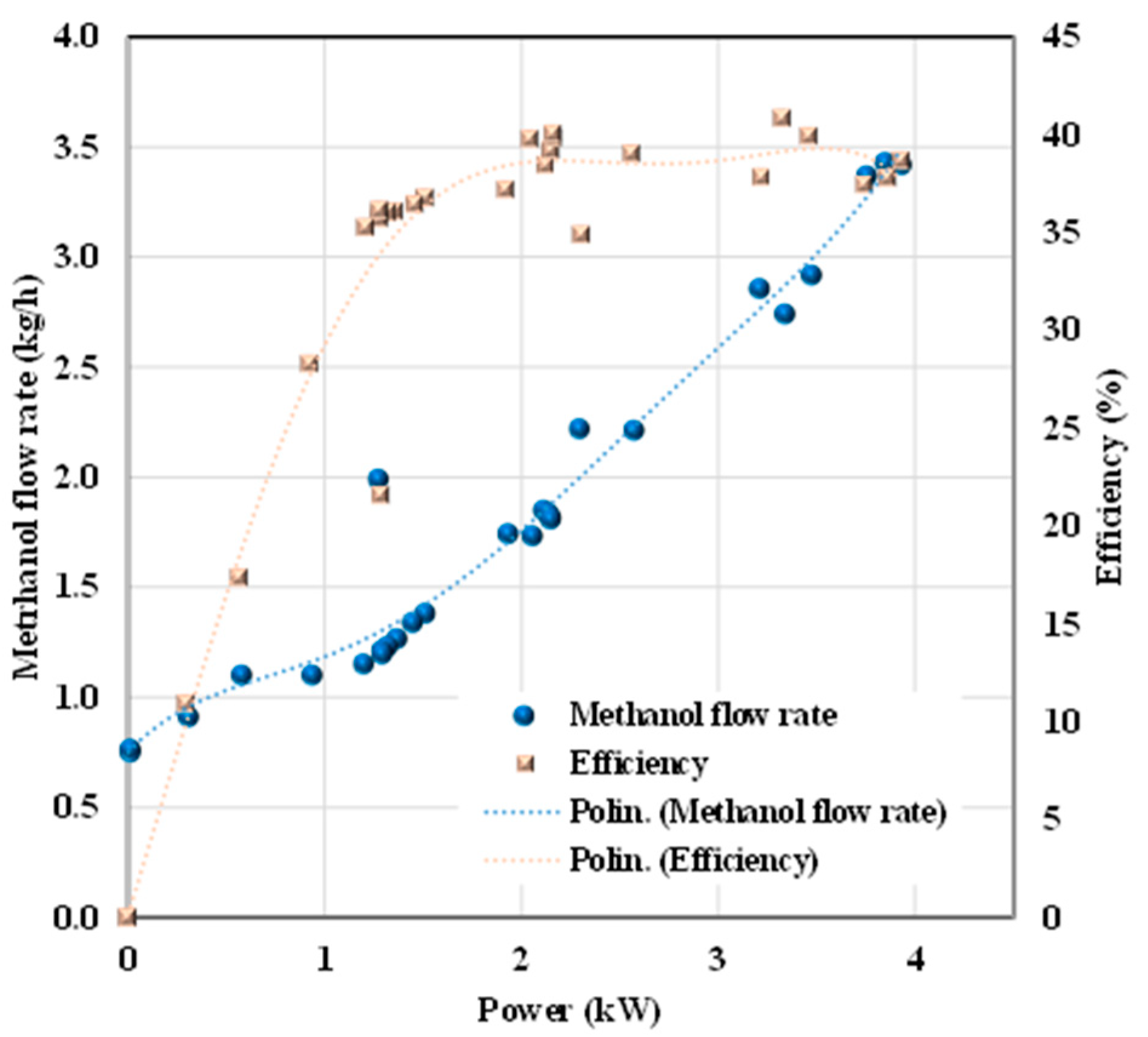
Methanol–water solution consumption was measured at different electrical powers, as illustrated in Figure 14. The results show that the inlet solution stream has an almost linear trend with the power, while the efficiency is referred to the power output downstream of the DC/DC converter. The system efficiency has been calculated as:
η = P o u t m ˙ C H 3 O H · H i
where Pout is the power output downstream of the DC/DC converter, m ˙ C H 3 O H is the flow of methanol, and H i   is the lower heating value of methanol.
The curve shows a rapid initial rise, followed by a nearly flat profile in a range between 2 and 4 kW, mostly influenced by the required power from the balance of plant (BoP).

3.2. Model Identification and Validation

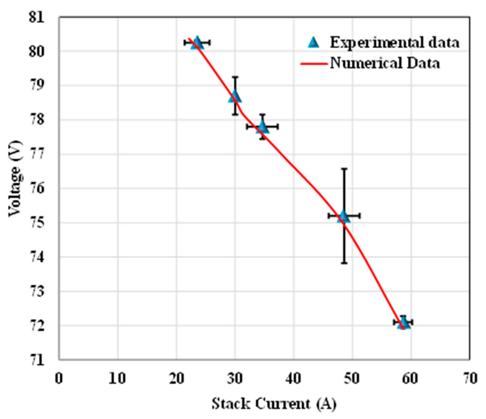
The model parameters identification has been carried out by calculating the electrical performance of the HT-PEMFC stack. In particular, for the voltage, the coefficient of Kim’s equation has been calculated by applying a regression technique based on the system experimental data. Table 7 lists the obtained results.
Figure 15 illustrates the comparison between the experimental and simulated data. It can be noticed that the simulation results match the experimental data with very good accuracy.
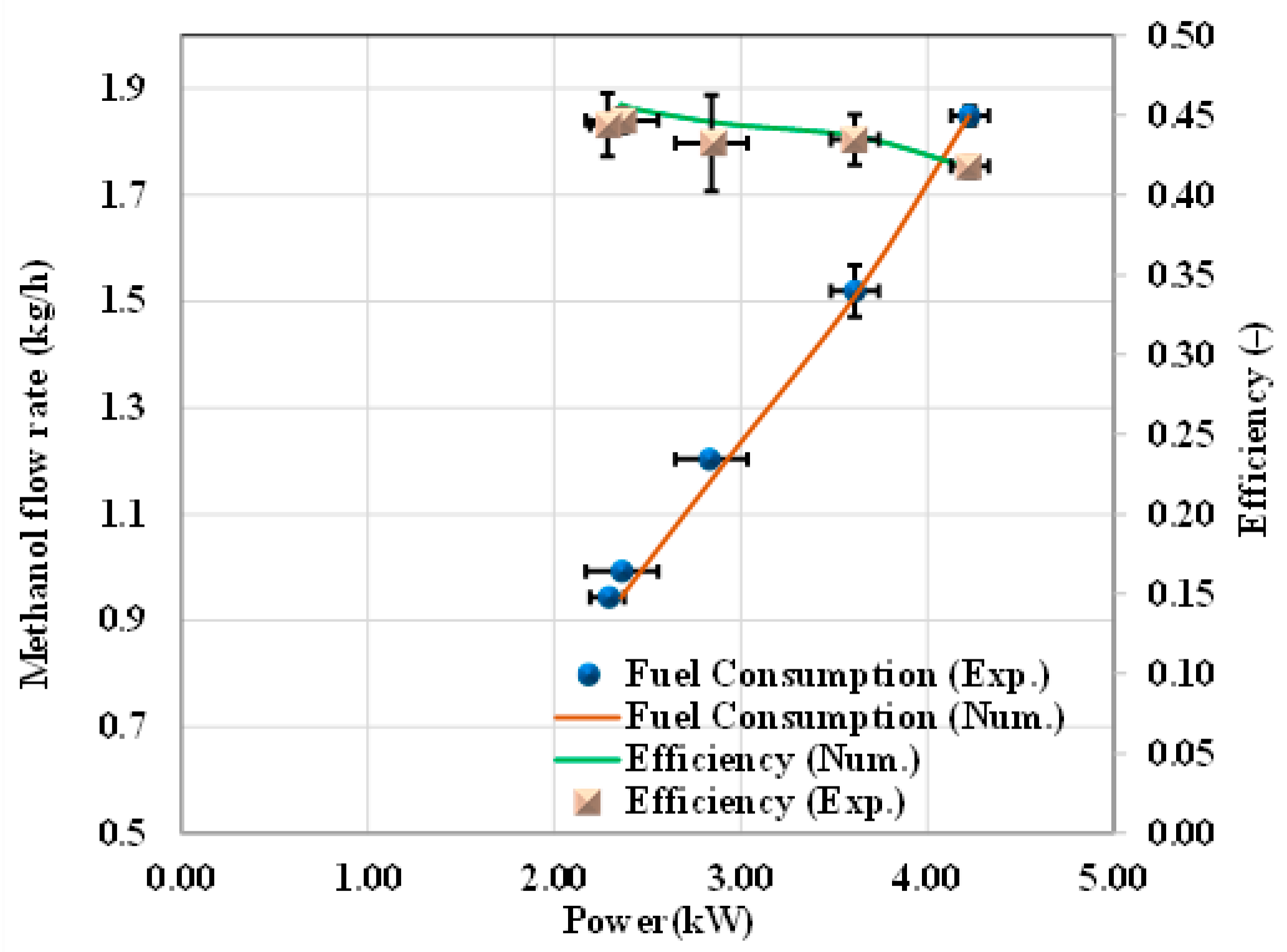
Once the fuel cell model was identified, the validation was carried out by calculating the operating data of the methanol HT-PEMFC system at the rated power. The performance of the system in terms of electric power and efficiency is calculated in the submodel developed in Fortran. Figure 16 shows the simulation results of the methanol mass flow rate and the efficiency vs. power, as related to the whole operating range of the system.
It can be noticed that the maximum mass flow rate of the methanol is 1.85 kg/h at 4.2 kW. At this operating condition, the calculated efficiency is 41%. The maximum efficiency, equal to 44%, is reached at a partial load (2.1 kW, i.e., 50% of the rated power), as expected.

3.3. Energies and Mass Balances

The energy and mass balances were also performed, considering different system operating conditions. Table 8 summarizes the data in terms of the mass flow rate and the temperature in different points of the system layout at the rated power, and also at 50% and 30% of the rated power (see Figure 16).

3.4. Feasibility Assessment

The architecture and sizing of propulsion and energy storage components in marine systems are largely influenced by the type of vessel and the intended mission profile. Variations in operating conditions, such as voyage duration, power demand, and environmental constraints, can lead to adjustments in the sizing of fuel cells, batteries, or other energy storage solutions.
The power system in this study is designed for application on the ship presented above. The fuel-reformed methanol fuel cells are the major power source in the system, and it is designed to meet the power request from the mission profile of the ship. The battery pack only provides support for sudden power demand during transient and start-up. Under these constraints, the ship can be powered by two HT-PEMFCs, delivering a nominal power of 4 kW each.
Regarding the operating point of the HT-PEMFCs, as illustrated in Figure 16, where the overall efficiency of the system and methanol consumption are shown, it can operate within the range 2 ÷ 4 kW without a significant impact on the overall system efficiency.
For the battery sizing, the minimum energy required to complete a full-electric circumnavigation of Capri was evaluated as equal to 2.28 kWh. This energy corresponds to the propulsion energy demand, assuming an overall efficiency of the electric system (motor and drives) of 0.85, and a constant ancillary load of 250 W. This energy can be supplied by three modules of the battery, as described in Table 5, in parallel configuration, considering a maximum state of charge of 90% and a minimum of 40%, as required by the energy management system.
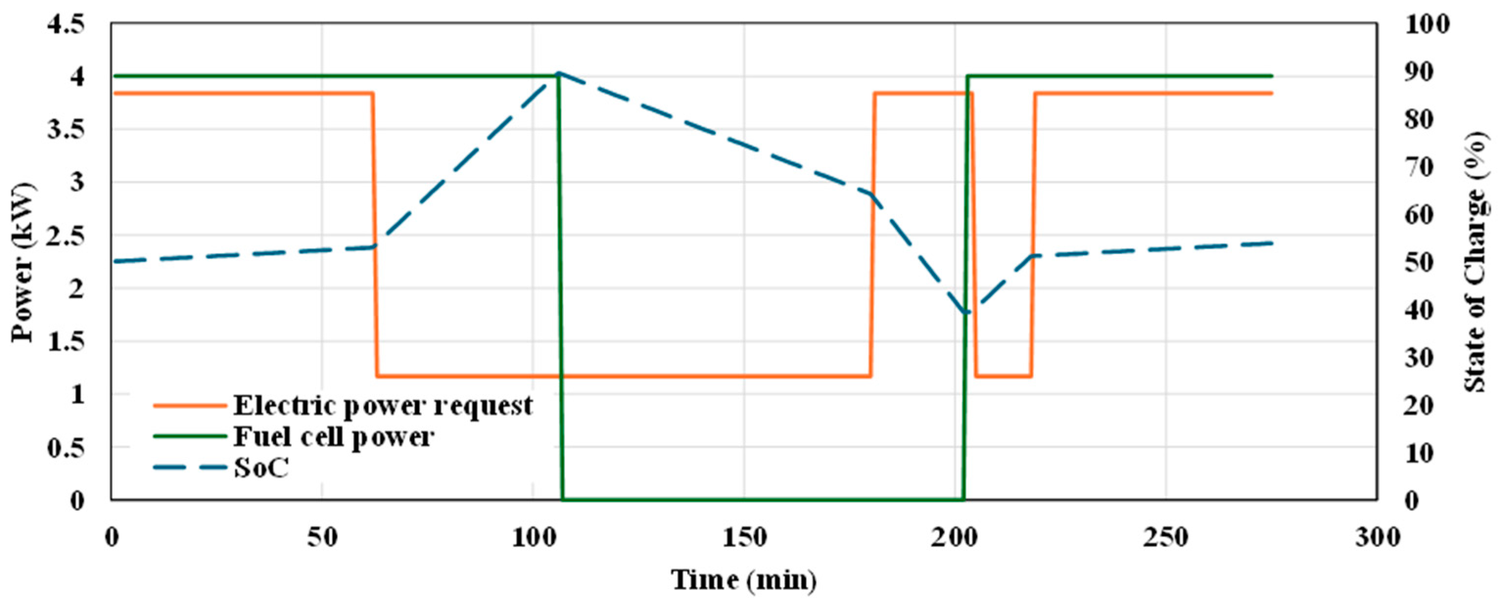
Once the system has been sized, its suitability can be validated by analyzing the results against the previously described mission profile. Based on the installed power and the actual power demand for propulsion and other loads, a working point of 2 kW per module (stack)—amounting to a total of 4 kW—was assumed. The results are shown in Figure 17, where it can be observed that the currently implemented energy management strategy, although it is not the most efficient, still achieves the desired outcome. This is accomplished with charge/discharge currents not exceeding 27 A. The total fuel consumption amounts to 12.7 kg, corresponding to a methanol consumption of 6.9 kg.
A more optimized energy management strategy would enable more efficient load sharing, reducing overall consumption while simultaneously allowing for a reduction in the required battery capacity, with evident benefits in terms of system weight, size, and cost.
The system’s main dimensions are summarized in Table 9, demonstrating that the weight and footprint of the system are fully compatible with the ship size and displacement. All weights are summarized in Table 9.
As shown in Figure 18, there is ample space for the installation of the entire propulsion system. In terms of weight, no significant issues arise, even at full capacity, assuming a maximum of 10 occupants (8 passengers and 2 crew members).

4. Conclusions

Methanol-based HT-PEMFCs can be considered as a promising solution for the decarbonization of the shipping sector. This study investigated the performance and feasibility of a high-temperature polymer electrolyte membrane fuel cell (HT-PEMFC) system powered by reformed methanol, intended as a sustainable propulsion solution for a 10 m commercial vessel operating in the marine area of Capri Island. A comprehensive approach combining both numerical and experimental analyses has been adopted. From a numerical perspective, a CFD model of the ship hull and a thermochemical model of the HT-PEMFC-based propulsion system have been developed to assess hydrodynamic performance and energy requirements. From the experimental standpoint, a dedicated test bench has been used to validate the operational behavior of the proposed fuel cell system.
The results demonstrate that the ship energy requirements can be met by installing two 5 kW HT-PEMFC units, a 5.07 Kwh Li-ion battery system, with an estimated total methanol consumption of 12.7 kg per cruise. Furthermore, the feasibility assessment confirmed that the proposed system is compatible with the ship’s dimensional and weight constraints, making it a viable alternative to conventional propulsion systems.
This study’s most relevant results include the successful estimation of the vessel’s energy needs, fully satisfied by a compact HT-PEMFC system supported by a Li-ion battery pack, and the low methanol consumption per cruise (12.7 kg), which confirms the system’s high efficiency. Moreover, the combined numerical and experimental approach allowed for a robust validation of both the hydrodynamic performance and fuel cell operation under realistic conditions. These outcomes clearly demonstrate the practicality and environmental benefits of integrating methanol-based HT-PEMFCs into small commercial vessels.

Author Contributions

Conceptualization, S.D.M., F.S., M.A., I.A. and M.M.; investigation, S.D.M., F.S., M.A., I.A. and M.M.; methodology, S.D.M., F.S., M.A., I.A. and M.M.; writing—original draft preparation, S.D.M., F.S., M.A., I.A. and M.M. All authors have read and agreed to the published version of the manuscript.

Funding

This work was funded by the European Union—NextGenerationEU under the project MOST “Spoke 3—Waterways” (CUP I63C22000340001).

Data Availability Statement

The original contributions presented in this study are included in the article. Further inquiries can be directed to the corresponding author.

Conflicts of Interest

The authors declare no conflicts of interest.

Nomenclature

AC Alternate Current
BoP Balance of Plant
BS Battery Simulator
CB Catalytic Burner
CFDs Computational Fluid Dynamics
CR Residual Resistance Coefficient
DC Direct Current
FC Fuel Cell
FN Froude Number
HIL Hardware-in-the-Loop
HT-PEMFCsHigh-Temperature Polymeric Exchange Membrane Fuel Cells
ITTC International Towing Tank Conference
Li-NMCLithium–Nickel–Manganese–Cobalt
SNMPSimple Network Management Protocol
SoCState of Charge
SOFCs Solid Oxide Fuel Cells

References

  1. Wang, Y.; Xiao, X.; Ji, Y. A Review of LCA Studies on Marine Alternative Fuels: Fuels, Methodology, Case Studies, and Recommendations. J. Mar. Sci. Eng. 2025, 13, 196. [Google Scholar] [CrossRef]
  2. Tai, T.-H.; Li, S.; Chang, Y.-C. Trends and Challenges in Maritime Energy Management; Springer Nature: Berlin/Heidelberg, Germany, 2020; Volume 197, p. 117223. [Google Scholar] [CrossRef]
  3. Adami, G.; Figari, M. Multi-Parametric Methodology for the Feasibility Assessment of Alternative-Fuelled Ships. J. Mar. Sci. Eng. 2024, 12, 905. [Google Scholar] [CrossRef]
  4. Bouman, E.A.; Lindstad, E.; Rialland, A.I.; Strømman, A.H. State-of-the-art technologies, measures, and potential for reducing GHG emissions from shipping—A review. Transp. Res. D Transp. Environ. 2017, 52, 408–421. [Google Scholar] [CrossRef]
  5. Trivyza, N.L.; Rentizelas, A.; Theotokatos, G.; Boulougouris, E. Decision support methods for sustainable ship energy systems: A state-of-the-art review. Energy 2022, 239, 122288. [Google Scholar] [CrossRef]
  6. Ortiz-Imedio, R.; Caglayan, D.G.; Ortiz, A.; Heinrichs, H.; Robinius, M.; Stolten, D.; Ortiz, I. Power-to-Ships: Future electricity and hydrogen demands for shipping on the Atlantic coast of Europe in 2050. Energy 2021, 228, 120660. [Google Scholar] [CrossRef]
  7. Russo, D.; Portarapillo, M.; Turco, M.; Di Benedetto, A. Towards H2-free shipboard storage: Energetic and risk analysis of oxidative methanol steam reforming in integrated fuel cell systems. Energy 2025, 320, 135376. [Google Scholar] [CrossRef]
  8. Tomos, B.A.D.; Stamford, L.; Welfle, A.; Larkin, A. Decarbonising international shipping—A life cycle perspective on alternative fuel options. Energy Convers. Manag. 2024, 299, 117848. [Google Scholar] [CrossRef]
  9. Frasci, E.; Sementa, P.; Arsie, I.; Vaglieco, B.M. Modeling and Experimental Validation of a Pure Methanol-Fueled Small SI Engine: Impact of the Laminar Flame Speed Correlation; SAE Technical Paper 2024-24-0033. 2024. Available online: https://www.sae.org/papers/modeling-experimental-validation-a-pure-methanol-fueled-small-si-engine-impact-laminar-flame-speed-correlation-2024-24-0033 (accessed on 18 June 2025). [CrossRef]
  10. Qu, J.; Feng, Y.; Zhu, Y.; Wu, B.; Wu, Y.; Xiao, Z.; Zheng, S. Assessment of a methanol-fueled integrated hybrid power system of solid oxide fuel cell and low-speed two-stroke engine for maritime application. Appl. Therm. Eng. 2023, 230, 120735. [Google Scholar] [CrossRef]
  11. Lv, J.; Sun, Y.; Zhang, Z.; Fang, Y. Optimization of operational parameters of marine methanol dual-fuel engine based on RSM-MOPSO. Process. Saf. Environ. Prot. 2024, 191, 2634–2652. [Google Scholar] [CrossRef]
  12. Di Micco, S.; Cigolotti, V.; Mastropasqua, L.; Brouwer, J.; Minutillo, M. Ammonia-powered ships: Concept design and feasibility assessment of powertrain systems for a sustainable approach in maritime industry. Energy Convers. Manag. X 2024, 22, 100539. [Google Scholar] [CrossRef]
  13. Seyam, S.; Dincer, I.; Agelin-Chaab, M. Optimization and comparative evaluation of novel marine engines integrated with fuel cells using sustainable fuel choices. Energy 2024, 301, 131629. [Google Scholar] [CrossRef]
  14. Gandiglio, M.; Marocco, P.; Nieminen, A.; Santarelli, M.; Kiviaho, J. Energy and environmental performance from field operation of commercial-scale SOFC systems. Int. J. Hydrogen Energy 2024, 85, 997–1009. [Google Scholar] [CrossRef]
  15. Wu, Z.; Zhu, P.; Yao, J.; Tan, P.; Xu, H.; Chen, B.; Yang, F.; Zhang, Z.; Ni, M. Thermo-economic modeling and analysis of an NG-fueled SOFC-WGS-TSA-PEMFC hybrid energy conversion system for stationary electricity power generation. Energy 2020, 192, 116613. [Google Scholar] [CrossRef]
  16. Fu, Z.; Lu, L.; Zhang, C.; Xu, Q.; Zhang, X.; Gao, Z.; Li, J. Fuel cell and hydrogen in maritime application: A review on aspects of technology, cost and regulations. Sustain. Energy Technol. Assess. 2023, 57, 103181. [Google Scholar] [CrossRef]
  17. Di Micco, S.; Minutillo, M.; Forcina, A.; Cigolotti, V.; Perna, A. Feasibility analysis of an innovative naval on-board power-train system with hydrogen- based PEMFC technology. E3S Web Conf. 2021, 312, 07009. [Google Scholar] [CrossRef]
  18. Di Micco, S.; Mastropasqua, L.; Cigolotti, V.; Minutillo, M.; Brouwer, J. A framework for the replacement analysis of a hydrogen-based polymer electrolyte membrane fuel cell technology on board ships: A step towards decarbonization in the maritime sector. Energy Convers. Manag. 2022, 267, 115893. [Google Scholar] [CrossRef]
  19. Pivetta, D.; Dall’Armi, C.; Taccani, R. Multi-objective optimization of hybrid PEMFC/Li-ion battery propulsion systems for small and medium size ferries. Int. J. Hydrogen Energy 2021, 46, 35949–35960. [Google Scholar] [CrossRef]
  20. Cavo, M.; Gadducci, E.; Rattazzi, D.; Rivarolo, M.; Magistri, L. Dynamic analysis of PEM fuel cells and metal hydrides on a zero-emission ship: A model-based approach. Int. J. Hydrogen Energy 2021, 46, 32630–32644. [Google Scholar] [CrossRef]
  21. Helgason, R.; Cook, D.; Davíðsdóttir, B. An evaluation of the cost-competitiveness of maritime fuels—A comparison of heavy fuel oil and methanol (renewable and natural gas) in Iceland. Sustain. Prod. Consum. 2020, 23, 236–248. [Google Scholar] [CrossRef]
  22. Thaler, B.; Kanchiralla, F.M.; Posch, S.; Pirker, G.; Wimmer, A.; Brynolf, S.; Wermuth, N. Optimal design and operation of maritime energy systems based on renewable methanol and closed carbon cycles. Energy Convers. Manag. 2022, 269, 116064. [Google Scholar] [CrossRef]
  23. Russo, D.; De Martino, M.; Di Benedetto, A.; Portarapillo, M.; Turco, M. Oxidative Methanol Reforming for Hydrogen-fed HT-PEMFC: Applications in the Naval Sector. Chem. Eng. Trans. 2023, 99, 367–372. [Google Scholar] [CrossRef]
  24. E4Ships. Available online: https://www.e4ships.de/english/maritime-shipping/pa-x-ell-2/ (accessed on 18 June 2025).
  25. Freudenberg e-Power Systems. Available online: https://www.freudenberg.com/press-media/press-releases/detail/ship-lengths-ahead (accessed on 25 June 2025).
  26. Blue World Technologies. Available online: https://www.blue.world/ (accessed on 25 June 2025).
  27. Advent Technology. Available online: https://advent.energy/advent-technologies-a-s-5kw-fuel-cell-systems-roll-out-in-asian-market-for-telecom-sector/ (accessed on 25 June 2025).
  28. Sorrentino, V.; Altosole, M.; De Luca, F.; Micoli, L.; Mocerino, L.; Russo, R. Preliminary modeling of a ferry methanol fuel cell power plant by using AVL Cruise M software. In Advances in Maritime Technology and Engineering; CRC Press: Boca Raton, FL, USA, 2024; pp. 63–70. [Google Scholar]
  29. ITTC-Recommended Procedures and Guidelines. Available online: https://ittc.info/media/1217/75-02-02-01.pdf (accessed on 25 June 2025).
  30. Balsamo, F.; Capasso, C.; Coppola, T.; Micoli, L.; Russo, R.; Veneri, O. A case study on High-Temperature Fuel Cells for Hybrid electric Ship Propulsion. In Proceedings of the 2023 IEEE International Conference on Electrical Systems for Aircraft, Railway, Ship Propulsion and Road Vehicles & International Transportation Electrification Conference (ESARS-ITEC), Venice, Italy, 29–31 March 2023; pp. 1–7. [Google Scholar] [CrossRef]
  31. Justesen, K.K.; Andreasen, S.J.; Pasupathi, S.; Pollet, B.G. Modeling and control of the output current of a Reformed Methanol Fuel Cell system. Int. J. Hydrogen Energy 2015, 40, 16521–16531. [Google Scholar] [CrossRef]
  32. Groene-Bootmotoren. Available online: https://groene-bootmotoren.nl/winkel/motoren/binnenmotor/water-world-10-0 (accessed on 25 June 2025).
  33. Clean Tech Batteries—Clean Tron. Available online: https://www.cleantron.nl/wp-content/uploads/2024/04/P4X.pdf (accessed on 25 June 2025).
  34. Garibaldi, D.; Bianchi, F.R.; Altosole, M.; Scamardella, F.; Balsamo, F.; Bosio, B. Plant Simulation of a Methanol Fueled HT PEM Fuel Cell for Ship Propulsion. In Proceedings of the 2024 IEEE International Conference on Electrical Systems for Aircraft, Railway, Ship Propulsion and Road Vehicles & International Transportation Electrification Conference (ESARS-ITEC), Naples, Italy, 26–29 November 2024; pp. 1–6. [Google Scholar] [CrossRef]
  35. Thomas, S.; Jeppesen, C.; Steenberg, T.; Araya, S.S.; Vang, J.R.; Kær, S.K. New load cycling strategy for enhanced durability of high temperature proton exchange membrane fuel cell. Int. J. Hydrogen Energy 2017, 42, 27230–27240. [Google Scholar] [CrossRef]
  36. Thomas, S. Operational Strategies for Longer Durability of HT-PEM Fuel Cells Operating on Reformed Methanol. Ph.D. Thesis, Aalborg University, Aalborg, Denmark, 2017. [Google Scholar]
  37. Song, K.; Hou, T.; Jiang, J.; Grigoriev, S.A.; Fan, F.; Qin, J.; Wang, Z.; Sun, C. Thermal management of liquid-cooled proton exchange membrane fuel cell: A review. J. Power Sources 2025, 648, 237227. [Google Scholar] [CrossRef]
  38. Sahlin, S.L.; Andreasen, S.J.; Kær, S.K. System model development for a methanol reformed 5 kW high temperature PEM fuel cell system. Int. J. Hydrogen Energy 2015, 40, 13080–13089. [Google Scholar] [CrossRef]
  39. Minutillo, M.; Perna, A.; Jannelli, E. SOFC and MCFC system level modeling for hybrid plants performance prediction. Int. J. Hydrogen Energy 2014, 39, 21688–21699. [Google Scholar] [CrossRef]
  40. Kim, J.; Lee, S.-M.; Srinivasan, S.; Chamberlin, C.E. Modeling of Proton Exchange Membrane Fuel Cell Performance with an Empirical Equation. J. Electrochem. Soc. 1995, 142, 2670–2674. [Google Scholar] [CrossRef]
  41. Jannelli, E.; Minutillo, M.; Perna, A. Analyzing microcogeneration systems based on LT-PEMFC and HT-PEMFC by energy balances. Appl. Energy 2013, 108, 82–91. [Google Scholar] [CrossRef]
Figure 1. Methodology flowchart.
Energies 18 05119 g001
Figure 2. Hull shape in two configurations: twin screw and single propeller.
Energies 18 05119 g002
Figure 3. Brake power vs. ship speed.
Energies 18 05119 g003
Figure 4. Capri marine area.
Energies 18 05119 g004
Figure 5. Ship power demand over distance travelled.
Energies 18 05119 g005
Figure 6. Ship propulsion system.
Energies 18 05119 g006
Figure 7. Scheme of the HT-PEMFC testing system.
Energies 18 05119 g007
Figure 8. Simplified internal flowsheet of the HT-PEM module and working temperature [34].
Energies 18 05119 g008
Figure 9. Web server synoptic scheme.
Energies 18 05119 g009
Figure 10. A picture of the system under testing.
Energies 18 05119 g010
Figure 11. HT-PEM system response to current variations at 320 V [30].
Energies 18 05119 g011
Figure 12. Flowsheet of the methanol-based HT-PEMFC system.
Energies 18 05119 g012
Figure 13. Fuel cell polarization curve (a) and power output (b).
Energies 18 05119 g013
Figure 14. Methanol–water stream at different generated electrical powers.
Energies 18 05119 g014
Figure 15. Polarization curve identification.
Energies 18 05119 g015
Figure 16. Power vs. fuel consumption and power vs. efficiency.
Energies 18 05119 g016
Figure 17. Ship mission profile simulation.
Energies 18 05119 g017
Figure 18. Ship general arrangement.
Energies 18 05119 g018
Table 1. Literature review.
Ref.SystemScope
[23]1 kW HT-PEMFCs fed by a methanol reformerDemonstration of a fully self-sustained system.
[24]90 kW HT-PEMFCs installed on board MS MariellaUse of HT-PEMFCs for auxiliary power generation.
[25]500 kW HT-PEMFC system for marine applicationPress release-type approval of the system from RINA for the safe use in marine environments.
[26]Up to 2 MW HT-PEMFC systemsPress release—development of the system for marine applications (mainly container vessels).
This study2 × 5 kW HT-PEMFCs for marine applicationThermodynamic modeling from experimental data on the system and feasibility analysis for installation on a 10 m boat for the full power system.
Table 2. CFD results.
Ship Speed
(VS)
Froude Number
(FN)
Residual Resistance
(CR)
(kn)(-)(-)
6.000.20 3.44 × 10 4
7.000.24 6.98 × 10 4
8.000.27 9.15 × 10 4
8.500.29 9.45 × 10 4
9.000.31 7.41 × 10 4
9.500.32 5.44 × 10 4
10.000.34 6.59 × 10 4
10.800.37 1.37 × 10 3
12.000.41 3.37 × 10 3
Table 3. Ship Characteristics.
Scale factor2.33-
Waterline length (LWL) 10.00m
Wetted surface 17.52m2
Waterline breadth (BWL)1.89m
Depth (T)0.55m
Hull volume3.61m3
Table 4. Ship resistance characterization.
Ship Speed
( V S )
Froude Number (FN)Residual Resistance
(CR)
Brake Power
(PB)
(kn)(-)(-)(W)
3.930.20 3.44 × 10 4 450
4.580.24 6.98 × 10 4 779
5.240.27 9.15 × 10 4 1217
5.570.29 9.45 × 10 4 1462
5.890.31 7.41 × 10 4 1624
6.220.32 5.44 × 10 4 1784
6.550.34 6.59 × 10 4 2144
7.070.37 1.37 × 10 3 3272
7.860.41 3.37 × 10 3 6747
Table 5. Battery pack main data [33].
Cells Capacity @ 1 A Discharge37 Ah
Nominal Voltage51.1 V
Capacity1890 Wh
Peak Discharge Current120 A
Dimensions429 × 266 × 78 mm
Weight12.4 kg
Table 6. Nominal data on the methanol-fueled HT-PEMFC system.
ParametersData
Anode feeding streamHydrogen rich gas
Cathode feeding streamAir
Nominal power 5 kW
Number of cells120
Number of stacks1
Minimum H2 stoichiometry1.35
Maximum utilization H20.74
O2 stoichiometry2–3
O2 utilization0.33–0.50
Reformer temperature270 °C
Stack temperature 160 °C
Ventilation outlet temperature<60°
Fuel (v/v methanol/water)60/40
Current change slope (load increase)30 mA/s
Current change slope (load decrease)60 mA/s
Active area 165 cm2
Exhaust temperature 160 °C
Table 7. Coefficient of Kim’s equation.
V 0 ( V ) b (V/dec) R (Ω cm2) m ( V ) n ( cm/A )
0.74070.03180.27690.0970.15
Table 8. Energy and mass balances of the CH3OH-based HT-PEMFC system at the rated power, 50% of the rated power, and 30% of the rated power.
FlowsMass Flow Rate (kg/h)T (°C)
System Power/Flows100%50%30%100%50%30%
CH3OH2.050.90.55252525
H2O1.370.60.37252525
13.421.50.92212121
23.421.50.92270270270
33.421.50.92270270270
ANODE-IN3.421.50.92160160160
AIR25.3013.246.06252525
451.5622.2513.21270270270
CATH-IN25.305.186.06160160160
ANODEOUT3.051.340.82160160160
CATH-OUT25.665.356.16160160160
AIRCB22.854.145.71252525
525.3013.246.06636567
651.5622.2513.21226230231
Table 9. Power system weights.
ItemWeight (kg)
HT-PEMFC2 × 65
Battery pack (3 modules)37
Electric motor76
Fuel tank63.5 (70 L tank)
Crew + passengers10 × 80
Ship displacement3698
Disclaimer/Publisher’s Note: The statements, opinions and data contained in all publications are solely those of the individual author(s) and contributor(s) and not of MDPI and/or the editor(s). MDPI and/or the editor(s) disclaim responsibility for any injury to people or property resulting from any ideas, methods, instructions or products referred to in the content.