Abstract
This paper presents the initial design of a permanent magnet synchronous machine with mechanically controlled excitation flux using the linear sliding motion of an additional excitation source placed inside a hollow shaft in the rotor. A new rotor design concept and assembling method are described and presented in detail. On the basis of 3D-FE analysis results, the principle of adjusting reluctance, magnetic flux distribution, flux linkage, field weakening rate, no-load back EMF waveforms, electromagnetic torque, magnetic tension, and the effectiveness of the excitation adjustment of the presented machine design are discussed. The presented machine concept enables the design of permanent magnet excited machines with a good flux control range operating in changing load conditions under variable rotor speed.
1. Introduction
The last three decades have seen a large number of publications related to the development of electric machines dedicated to traction applications, especially for electric vehicle (EV) drives. Among the many different types of electric machines, there are four types of machines, namely, induction machines, electrically excited synchronous machines, switched reluctance machines, and permanent magnet (PM) machines, that are practically suitable for EV drives. The basic characteristics of an electric drive for EVs are as follows: high efficiency, high torque and high power density, wide speed range and constant-power operating capability, reliability and robustness, low acoustic noise, and low cost. Being continually fuelled by new motor topologies and control strategies, PM synchronous machines have been identified to be the most promising to provide the aforesaid characteristics for modern EVs, and for hybrid electric vehicles (HEVs) as well. The greatest advantage of MP machines is the removal of brushes and commutation, leading to the elimination of many technical problems. However, it should be noted that the other previously mentioned machines, despite their relatively lower efficiency compared to PM machines, are also successfully developed and currently used in EV drives, and this especially applies to electrically excited synchronous machines.
EVs are commonly equipped with a battery and power converters, which determine the maximum voltage and power in the EV drive system based on their limitations. The optimal utilization of the EV drive system is reached when operating the components at their limits with maximum power over a wide speed range. It should be added that electrical machines usually need to operate above the base speed. In general, the application of EV drives requires variable speed and high-speed operation, a constant-power operation region that can be extended by using field-weakening (FW) control methods. There are five different FW methods for synchronous machines. Generally, physical possibilities for adjusting air-gap flux density to control the main flux of the machine are related to direct changing of ampere turns, serial/parallel integration of additional ampere turns, or changing the reluctance in the main flux or the leakage flux path. Focusing on the foremost criteria of EV drives with PM machines, the design philosophy can consist of two approaches. The first one lies in the development of a specially configured drive with a PM synchronous machine incorporating an optimal control strategy. The second one is to develop specially designed hybrid excited (HE) motor drives by using machines containing both PMs and additional field winding for field weakening or specially designed PM machines with a mechanically adjusted permanent magnet (MAPM) system. Here, it can be mentioned that there are many attractive features that result from HE and MAPM systems, such as easily adjustable air-gap flux density, superbly high torque through flux strengthening, wide-speed constant-power through field weakening, maintained constant output terminal voltage, and efficiency-optimizing control through online tuning of the air-gap flux density. Moreover, HE and MAPM systems provide an additional degree of freedom in machine design and development flexibility. Hence, the useful performance of machines with HE or MAPM systems, in terms of operational flexibility at high speeds and their high efficiency in motor mode, has gathered mounting attention in the last two decades [1,2,3,4,5,6,7,8,9,10,11,12,13,14,15,16,17]. Furthermore, in generator mode, HE or MAPM machines can also be an attractive alternative to typical PM synchronous machines coupled with a controlled rectifier.
MAPM machines can offer advantages of simple and straight manipulation for FW instead of more complicated armature current control, as is used in PM machines, where the well-known application of a current in the negative d-axis in the rotor fixed d- and q-coordinate system is incorporated, and in HE machines where, in addition to the armature current control, a secondary system to supply additional field winding is required. However, MAPM machines require external actuators, which can often be mechanically complicated and need controllers and maintenance and consume power.
MAPM machines can be divided into two groups: machines with axially displaceable rotors to control the position between the rotor and the stator [18,19] and twisted machines equipped with one rotatable rotor [20]. Among them, the interesting concept of MAPM machines with flexibly movable short-circuit iron pieces is presented in [21]. According to the state of the art, it can be concluded that, due to the elimination of copper losses for flux control of the MAPM machine, the machine efficiency tends to be improved in a wide operation range.
The main part of this paper is dedicated to a rotor design with a new MAPM system to adjust the reluctance in the main and leakage flux paths of a PM machine for FW purposes.
2. Principle of the New Machine Design Concept
PM machines with distributed stator windings and embedded magnets in the rotor confirm an extended FW range and offer an excellent base for further improvement. Concerning their application in an EV or HEV, there are important disadvantages of PM machines with fixed rotor excitation: no-load losses, particularly at medium to high speeds, and short circuit currents. Regarding states of faults in an inverter or windings of the machine, short circuit currents are particularly undesired because their consequences can be severe. Consequently, a new MAPM machine design concept with a novel rotor design containing an additional mechanically positioned excitation source (MPES) placed in a hollow shaft has been developed and is shown in the cross-section in Figure 1.
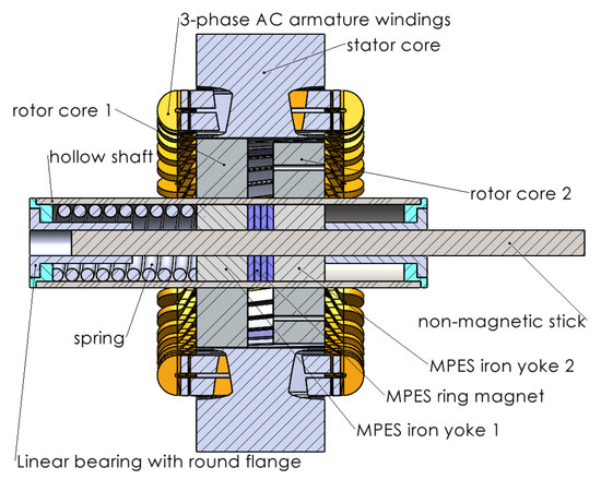
Figure 1.
Cross-section of a new MAPM machine design concept.
An MAPM machine design applies a unique mechanical system to achieve air-gap flux density adjustment without using field winding, and the machine can be classified as a novel mechanically adjusted PM machine with an axially movable iron and magnet in the rotor. The presented design concept has been developed on the basis of experience gained during research work on the Electric Controlled Permanent Magnet Synchronous machine (ECPMS machine) with an additional excitation coil placed on the stator, or on the rotor, for flux regulation purposes, described in detail in [22,23,24,25]. One of the technical problems of the ECPMS machine is related to the need to use an additional power supply system for the excitation coil, which requires sufficient power and generates additional losses, affecting the efficiency of the entire drive system. Furthermore, there are some difficulties in developing a suitable cooling system for the ECPMS machine.
In the MAPM machine design concept, the stator and main parts of the rotor yoke of the ECPMS machine will be adopted for an MAPM machine prototype. Hence, for the completely built stator with 3-phase AC armature windings and rotor cores, a new rotor with a diameter of 163.0 mm was designed using finite element analysis.
The rotor design contains two rotor yokes fixed on a hollow shaft. In this case, what is unique is that the hollow shaft has a through axial hole inside in which there is a mechanically positioned excitation source (MPES). As shown in Figure 1, the MPES includes a ring magnet (MPES ring magnet) and two yokes (MPES yoke 1 and MPES yoke 2), which are mounted on a non-magnetic stick that slides in two linear bearings. It should be noted here that, in the presented machine design concept, there are no additional field windings, so the above-mentioned problems do not occur in this solution.
The main data of the machine design are listed in Table 1.

Table 1.
The main data of the machine.
The rotor design (Figure 2) has many components, namely, the hollow shaft, two rotor cores with embedded magnets, and the MPES. Each rotor core is made in a specific way. The poles in the rotor are made of a permanent magnet pole (PM pole) and an iron pole. In this case, the PM poles of the first rotor core (rotor core 1) are arranged in a straight line along the iron poles opposite the second rotor core (rotor core 2). Similarly, the iron poles of the first rotor core are located opposite the magnet poles of the second rotor core. Each PM pole consists of four magnet rows, where rectangular-shaped permanent magnets are embedded, and a single magnetic barrier in cuboid shape. The iron poles are placed between the PM poles. The flux barriers and embedded permanent magnets are arranged inside the rotor laminations as shown in Figure 3.
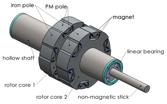
Figure 2.
View of rotor design.
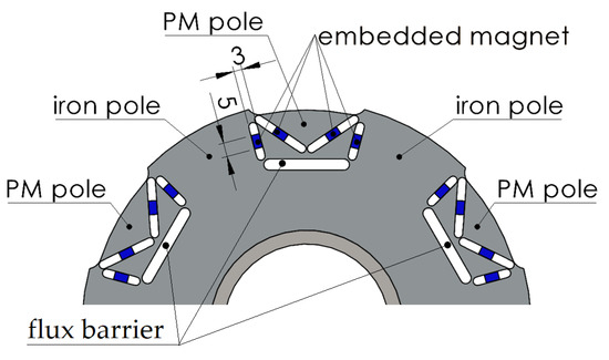
Figure 3.
Multi-flux barrier rotor lamination with embedded magnets.
The MPES placed in the hollow shaft of the rotor can be built from simple, available components, which are shown in Figure 4.
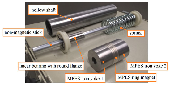
Figure 4.
Components of the MPES within a hollow shaft.
The MPES can change position in one direction along the shaft axis by applying an axial force to the non-magnetic stick from an external mechanical system. The MPES returns to its initial position as the result of the spring force. The position of the MPES significantly affects the distribution of the magnetic field in the machine. Thanks to this feature, it is possible to change the actual excitation flux of the MAPM machine as a result of changing the position of the MPES inside the hollow shaft.
3. Adjusting Reluctance
The principle of magnetic flux distribution in the machine for the two extreme positions (position 0 and position 5) of the MPES is shown in Figure 5a,b. Based on the presented magnetic flux partition, a simplified reluctance circuit for the MAPM machine design concept could be produced, as shown in Figure 5c.
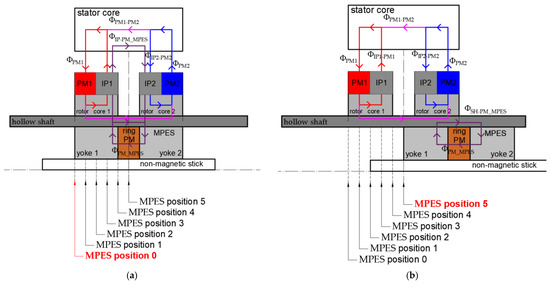
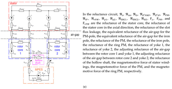
Figure 5.
The principle of magnetic flux distribution on a schematic diagram of a machine for two extreme MPES positions: (a) MPES position 0; (b) MPES position 5; and a simplified reluctance circuit for MAPM machine design concept (c).
By neglecting the saturation effect and flux leakage of the MAPM machine, it can be assumed that a flux component generated by PMs, which are embedded in rotor core 1 (ΦPM1) and rotor core 2 (ΦPM2), according to Figure 5a,b, crosses the air-gap over magnet poles in the radial direction and then the main part of the flux flows through the stator core in the axial direction (ΦPM1-PM2) and returned through the rotor core 1, an iron hollow shaft and the rotor core 2. The remaining part of the flux generated by PM1 is returned to the iron pole 1 (ΦIP1-PM1). In the same way, the remaining part of the flux generated by PM2 is returned to the iron pole 2 (ΦIP2-PM2). It is characteristic that the magnetic flux excited by the ring magnet (ΦPM_MPES) is distributed in a specific way.
It should be noted that, according to Figure 5c, the reluctances of the air-gap in the region between rotor core 1 and yoke 1 and the region between rotor core 2 and yoke 2 vary with MPES position, and this is a very important feature of the MAPM machine design concept.
The distribution of magnetic flux varies depending on the actual position of the MPES in relation to the rotor cores. On the basis of the 3D-FEA results presented in Figure 6, one can clearly observe the changing air-gap magnetic flux density distribution. The results unilaterally show that greater magnetic field amplification occurs at position 0 (Figure 6a) compared to position 5 (Figure 5b).
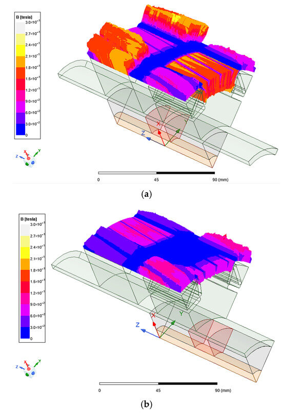
Figure 6.
Air-gap vector field of magnetic flux density distribution: (a) MPES position 0 and (b) MPES position 5.
The presented results show that, when the MPES is repositioned, the magnitude of the magnetic field vectors observed in the middle of the air-gap under the PM pole changes much less compared to the magnitude of the magnetic field vectors observed in the middle of the air-gap under the iron pole. Hence, it can be concluded that the proposed geometry of the rotor magnetic structure blocks magnetic flux passing through the PM pole effectively with magnetic barriers. This effect is also the result of a change in the distribution of the magnetic flux excited by the ring magnet, which is mounted in the MPES. Figure 7 shows the magnetic flux density distribution in the rotor, where it can also be seen that magnetic saturation occurs in the hollow shaft. At MPES position 5 (Figure 7b), the flux excited by the ring magnet ΦPM_MPES (according to Figure 5b) will pass through yoke 1 and then turn in the axial direction to form shaft flux Φsh-PM_MPES and return to the magnet through yoke 2. The highest value of the excitation flux will be at position 0 according to Figure 7a, where a part of the shaft flux will pass through the iron poles ΦIP-PM_MPES.
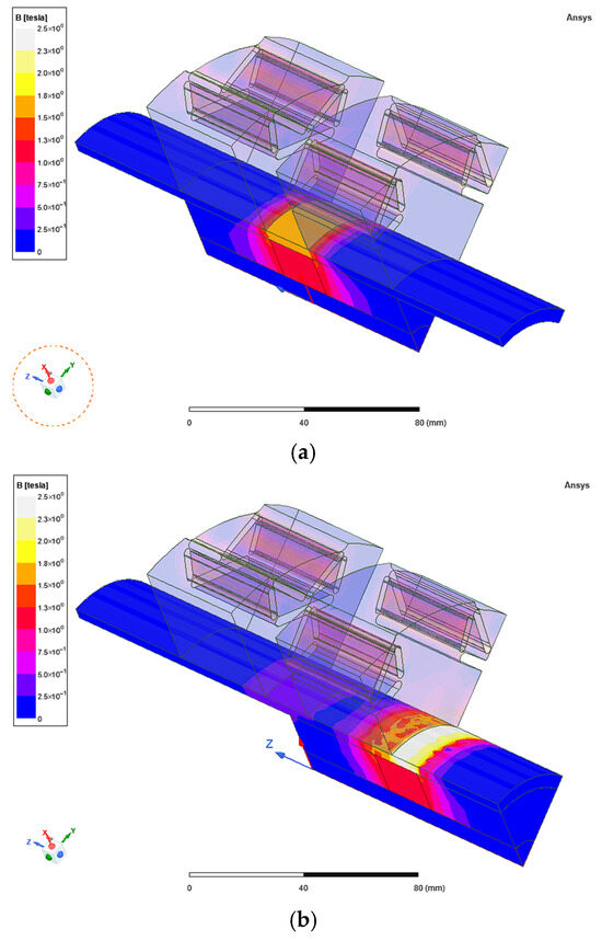
Figure 7.
Magnetic flux density distribution in the 3D-FE-model of the rotor: (a) MPES position 0 and (b) MPES position 5.
The presented results show that the excitation flux of the machine can be strongly determined by the MPES position and magnetomotive force of the ring magnet.
The presented analysis of the magnetic field distribution of the MAPM machine at the different positions of the MPES was performed by using 3D-FEM models of the machine developed in Ansys Electronics Desktop 2024 R1, taking into account nonlinear B-H curves of ferromagnetic materials.
4. Flux Linkage and Flux Weakening Rate
The armature flux linkage Ψs of the presented machine is the sum of the excitation flux Φexc and the flux of armature magnetic reaction Φarm. In general, excitation flux Φexc has two components: first, permanent magnets flux linkage ΦPM excited by embedded magnets; second, additional permanent magnets flux linkage ΦaddPM excited by the ring permanent magnet, which is the function of the MPES position.
In order to determine a flux weakening rate denoted by Δψ, an additional 3D-FE analysis was carried out. At this time, a hybridization rate Δψ is defined as the ratio of maximal flux linkage ψsmax0 obtained at MPES position 0 to minimal flux linkage ψsmax5 achieved at MPES position 5. Figure 8 shows the no-load armature flux linkage Ψs waveforms achieved at the three different MPES positions.
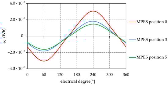
Figure 8.
No-load armature flux linkage waveforms at the different MPES positions.
In Figure 8, one can clearly see the field-weakening effect, which decreases the value of armature flux linkage from 30.4 mWb to 14.4 mWb, while the MPSE position was changed from position 0 to position 5, and this means that the value Δψ is equal to 2.1. Assuming that the value of permanent magnets’ flux linkage, ΦPM, excited by embedded magnets, does not change significantly depending on the MPES position, an additional permanent magnet flux linkage, ΦaddPM, has been estimated. As shown in Figure 9, there is an additional permanent magnet flux linkage, ΦaddPM, characteristic of MPES positions.
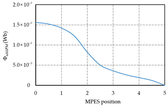
Figure 9.
An additional permanent magnet flux linkage, ΦaddPM, characteristic versus MPES positions.
5. No-Load Back EMF
An electromotive force e of a multi-turn winding of the machine is induced by changing the excitation flux Φexc and is written as:
where —winding factor and N—turns of winding.
In order to examine the values and waveforms of the voltage induced in the phase windings of the machine, 3D-FE analysis of the back-EMF waveforms at different MPES positions was carried out. Figure 10 shows the induced phase voltage Uph (rms values), characteristic versus MPES positions at a constant rotor speed of 1000 rpm. Figure 11 shows back-EMF waveforms induced at a rotor speed of 1000 rpm for the MPES positions 0 and 5, in comparison. In this case, a no-load voltage can be adjusted in the range of 6.6 Vrms to 13.0 Vrms, and this makes it possible to reduce the value of the induced voltage in the ratio of 2:1.
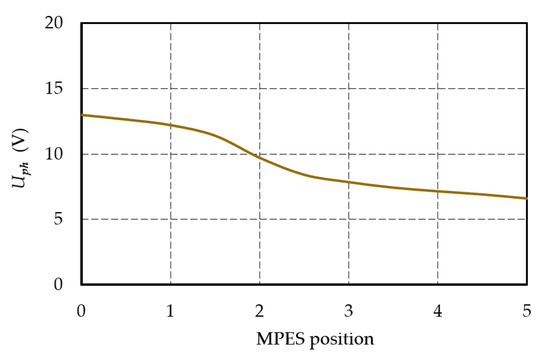
Figure 10.
Induced phase voltage Uph characteristic versus MPES positions at a rotor speed of 1000 rpm.
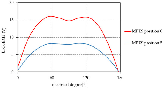
Figure 11.
The 3D-FEA results of phase back-emf waveforms performed at a rotor speed of 1000 rpm at two extreme MPES positions.
Based on the results, assuming that the motor is operating at high speed and the supply voltage limit is reached, this means that the motor is working in the field-weakening region (MPES position between 0–5). It can be concluded that the magnetic field can be weakened by increasing the no-load rotation speed or strengthened by decreasing it. Under load operating conditions, the dynamic process in change of rotation speed will mainly depend on the torque load, machine current limits, and the speed of changing the position of the MPES.
6. Electromagnetic Torque and Magnetic Tension
A simplified mathematical model describing the presented machine can be easily developed under the assumption that armature windings’ inductance and resistance are symmetric and constant; the flux of permanent magnets remains stable; the magnetic circuit is linear; and the higher harmonics of an air-gap magnetic flux density are neglected. Finally, the d- and q-axis voltages and the electromagnetic torque of the machine can be written as:
where p—number of pair poles; Ψd, Ψq—d- and q-axis magnetic fluxes; Id, Iq—d- and q-axis stator currents; R—resistance of armature windings; Ld, Lq—d- and q-axis inductances.
Equation (4) shows the possibility of creating a specified electromagnetic torque at different values of the individual components of the stator current (Id, Iq) and additional permanent magnet flux linkage excited by a ring permanent magnet.
Owing to the fact that it is possible to control the flux control by positioning the ring permanent magnet, it is also possible to produce a torque under different armature current components Id and Iq. If extreme torque values are needed at low speeds, the machine flux can be strengthened. On the other hand, if it is necessary to maintain torque with increased flux excitation, the stator current can be reduced, and this can improve the effectiveness of the machine. As already mentioned above, at high speed, a stator current control strategy requires field-weakening. Moreover, reducing the flux excitation can also affect the decrease in the magnetic losses of the machine.
Moreover, due to the occurrence of asymmetry of magnetic fluxes in the magnetic circuit of the machine, the magnetic tension acting on the rotor was analyzed. For this purpose, the axial forces (Z-direction accordingly in Figure 12) acting on the rotor (Figure 12a) and MPES (Figure 12b) were determined, and the results of the forces acting on the rotor and MPES versus PMES position characteristics are shown in Figure 13. The obtained results showed that the value of the axial force acting on the rotor and MPES is quite low and amounts to a maximum of 4.2 N. However, the calculated value of the axial force was taken into account during the analysis of the external force that should be used to move the MPES and during the selection of the spring to be used inside the MPES system.
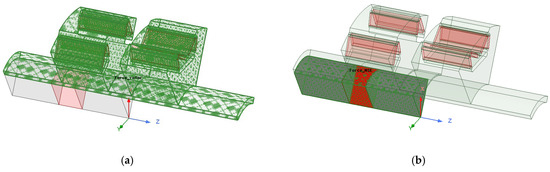
Figure 12.
View of model objects (marked in green) subjected to axial force analysis: (a) for the rotor and (b) for the MPES.
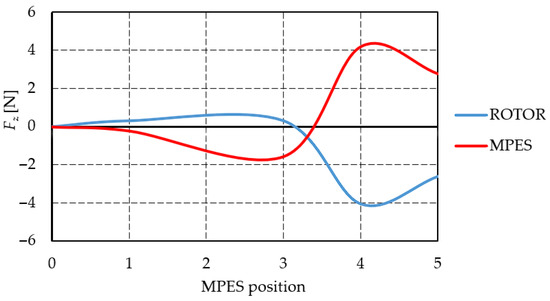
Figure 13.
Rotor and MPES magnetic tension characteristics versus MPES positions.
The presented results show that the influence of the MPES position on the direction and action of the axial force is quite significant. Between positions 3 and 4, there is a change in the direction of the axial force, so this is the position at which a mechanical system for positioning the MPES must be resistant to the loss of MPES position stability. However, it should also be noted that in this case, the value of the axial force acting on the rotor is relatively small (the axial force amplitude is about 5 N).
7. Discussion
Adjusting the excitation of a permanent magnet electric machine is complex and requires the use of field-weakening techniques and proper vector stator current control strategies. The presented machine design with a new method of field-weakening does not require the use of an additional power electronic system to supply the additional excitation coil and advanced control methods that are used in wireless supply control systems. Thanks to the relatively simple design mechanism for positioning an additional excitation source, it is possible to design a permanent magnet excited machine with a good flux control range, and this can improve the performance, efficiency, stability, and operation range of electric machines with permanent magnets that work in changing operation conditions, under variable load and/or variable rotor speed. The position of the MPES system should be coordinated with the operating states of the machine. This means that for each point of operation of the machine, the position of the PMES must be strictly defined for the selected control strategy.
It should also be noted that the presented machine concept must have an additional external mechanical system to activate the MPES system, which can be a technical challenge as well, given the relatively small dimensions of such systems. The key here is to design a mechanical system to couple the non-magnetic stick with the additional positioning system and maintain a stable position of the PMES system during its rotation operation. Several ways to solve this problem can be considered. One way could be to design the additional positioning system using a movable magnetic clutch that will be positioned by an actuator, a linear tubular reluctance motor, or by using rotary push–pull lever control systems.
The article presents a machine design solution that has been made in an unconventional, previously unknown way. So far, such a design of MAPM machines with the presented mechanically positioned excitation source has not been described in the literature or in any application. The MPES within the hollow shaft of the rotor can be built from simple components such as springs, hollow shaft, cylindrical iron, magnet rings, and linear bearings, and as is known, all of these components are widely available.
What is unique is that the presented design of the PMES system can be successfully adapted to both axial-flux and radial-flux machines. The machine design can also be used in direct-drive applications requiring high power density and a wide speed range. AMPM machines with the PMES system will have the opportunity to control the excitation in a mechanical way, allowing for a decrease in induced voltage and short circuit current of the machine. In general, the presented MAPM machine with the PMES rotor design shows advantages and promises a good potential for further development and improvements.
8. Conclusions
In this paper, the initial design of a permanent magnet synchronous machine with mechanically controlled excitation flux using linear sliding motion of an additional excitation source placed inside a hollow shaft in the rotor has been discussed. A new rotor design concept and assembling method have been described and presented in detail.
On the basis of 3D-FE analysis results, magnetic flux distribution, air-gap magnetic flux density, flux linkage, no-load back EMF waveforms, electromagnetic torque, and magnetic tension, and the effectiveness of the excitation adjustment of the presented machine design have been successfully determined. The FEA results confirmed the effectiveness of the excitation adjustment of the presented machine design in the ratio 2:1 obtained with the available displacement range of the MPES system.
It can be concluded that the presented machine concept with an external mechanical system to activate the MPES system enables to design of permanent magnet excited machines with a good flux control range operating in changing load conditions under variable rotor speed and has great potential for further development.
9. Patents
The results of the work reported in this manuscript are patented at the Patent Office of the Republic of Poland (patent no. P.440874).
Funding
This research received no external funding.
Data Availability Statement
Data are contained within the article.
Conflicts of Interest
The author declares no conflicts of interest.
References
- Amara, Y.; Ben Ahmed, H.; Gabsi, M. Hybrid Excited Synchronous Machines: Topologies, Design and Analysis; John Wiley & Sons: Hoboken, NJ, USA, 2024. [Google Scholar]
- Hlioui, S.; Gabsi, M.; Ben Ahmed, H.; Barakat, G.; Amara, Y.; Chabour, F.; Paulides, J.J.H. Hybrid excited synchronous machines. IEEE Trans. Magn. 2022, 58, 8101610. [Google Scholar] [CrossRef]
- Amara, Y.; Hlioui, S.; Gabsi, M. Overview of Degrees of Freedom in the Design of PM Synchronous Machines. Energies 2021, 14, 3990. [Google Scholar] [CrossRef]
- Michieletto, D.; Cinti, L.; Bianchi, N. Hybrid Excitation PM Synchronous Motors: Part I—Per Unit Analysis. IEEE Trans. Energy Convers. 2022, 37, 487–494. [Google Scholar] [CrossRef]
- Amara, Y.; Hlioui, S.; Ben Ahmed, H.; Gabsi, M. Preoptimization of hybridization ratio in hybrid excitation synchronous machines using electrical circuits modelling. Math. Comput. Simul. 2021, 184, 118–136. [Google Scholar] [CrossRef]
- Zhu, Z.Q.; Cai, S. Hybrid excited permanent magnet machines for electric and hybrid electric vehicles. CES Trans. Electr. Mach. Syst. 2019, 3, 233–247. [Google Scholar] [CrossRef]
- Asfirane, S.; Hlioui, S.; Amara, Y.; Gabsi, M. Study of a hybrid excitation synchronous machine: Modeling and experimental validation. Math. Comput. 2019, 24, 34. [Google Scholar] [CrossRef]
- Wang, Q.; Niu, S.; Luo, X. A Novel Hybrid Dual-PM Machine Excited by AC With DC Bias for Electric Vehicle Propulsion. IEEE Trans. Ind. Electron. 2017, 64, 6908–6919. [Google Scholar] [CrossRef]
- Hua, H.; Zhu, Z.Q.; Zhan, H. Novel Consequent-Pole Hybrid Excited Machine with Separated Excitation Stator. IEEE Trans. Ind. Electron. 2016, 63, 4718–4728. [Google Scholar] [CrossRef]
- Afinowi, I.A.A.; Zhu, Z.Q.; Guan, Y.; Mipo, J.C.; Farah, P. Hybrid-Excited Doubly Salient Synchronous Machine With Permanent Magnets Between Adjacent Salient Stator Poles. IEEE Trans. Magn. 2015, 51, 8107909. [Google Scholar] [CrossRef]
- Tapia, J.A.; Leonardi, F.; Lipo, T.A. Consequent-Pole Permanent-Magnet Machine with Extended Field-Weakening Capability. IEEE Trans. Ind. Appl. 2003, 39, 1704–1709. [Google Scholar] [CrossRef]
- Hwang, S.W.; Sim, J.H.; Hong, J.P.; Lee, J.Y. Torque Improvement of Wound Field Synchronous Motor for Electric Vehicle by PM-Assist. IEEE Trans. Ind. Appl. 2018, 54, 3252–3259. [Google Scholar] [CrossRef]
- Kong, L.; Wen, X.; Fan, T. A new method to plan the optimal field excitation current trajectory in a hybrid excitation machine. In Proceedings of the 2011 International Conference on Electrical Machines and Systems, Beijing, China, 20–23 August 2011; pp. 20–23. [Google Scholar]
- Mörée, G.; Leijon, M. Overview of Hybrid Excitation in Electrical Machines. Energies 2022, 15, 7254. [Google Scholar] [CrossRef]
- Zhou, Z.; Hua, H.; Zhu, Z. Flux-Adjustable Permanent Magnet Machines in Traction Applications. World Electr. Veh. J. 2022, 13, 60. [Google Scholar] [CrossRef]
- Bianchi, N.; Carlet, P.G.; Cinti, L.; Ortombina, L. A Review about field-Weakening Operating Limits and Control Techniques for Synchronous Motor Drives. Energies 2022, 15, 1930. [Google Scholar] [CrossRef]
- Chu, W.Q.; Zhu, Z.Q.; Chen, J.T. Simplified Analytical Optimization and Comparison of Torque Densities Between Electrically Excited and Permanent-Magnet Machines. IEEE Trans. Ind. Electron. 2014, 61, 5000–5011. [Google Scholar] [CrossRef]
- Zepp, L.P.; Medlin, J.W. Brushless Permanent Magnet Motor or Alternator with Variable Axial Rotor/Stator Alignment to Increase Speed Capability. US 6555941 B1, 29 April 2003. [Google Scholar]
- Ma, L.; Sanada, M.; Morimoto, S.; Takeda, Y.; Matsui, N. High efficiency adjustable speed control of IPMSM with variable permanent magnet flux linkage. In Proceedings of the Conference Record of the 1999 IEEE Industry Applications Conference, Thirty-Forth IAS Annual Meeting (Cat. No.99CH36370), Phoenix, AZ, USA, 3–7 October 1999; Volume 2, pp. 881–887. [Google Scholar]
- Woehl-Bruhn, H.; Canders, W.R.; Domann, N. Classification of field-weakening solutions and novel PM machine with adjustable excitation. In Proceedings of the XIX International Conference on Electrical Machines—ICEM 2010, Rome, Italy, 6–8 September 2010; pp. 1–6. [Google Scholar] [CrossRef]
- Owen, R.; Zhu, Z.Q.; Wang, J.B.; Stone, D.A.; Urquhart, I. Mechanically adjusted variable-flux concept for switched-flux permanent-magnet machines. In Proceedings of the International Conference on Electrical Machines and System, Beijing, China, 20–23 August 2011; pp. 1–3. [Google Scholar]
- Paplicki, P. Influence of Magnet and Flux-Barrier Arrangement on Flux Control Characteristics of Hybrid Excited ECPMS-machine. Elektron. Elektrotechn. 2017, 23, 15–20. [Google Scholar] [CrossRef]
- Paplicki, P. A novel rotor design for a hybrid excited synchronous machine. Arch. Electr. Eng. 2017, 66, 29–40. [Google Scholar] [CrossRef][Green Version]
- Wardach, M.; Palka, R.; Paplicki, P.; Bonislawski, M. Novel hybrid excited machine with flux barriers in rotor structure. COMPEL 2018, 37, 1489–1499. [Google Scholar] [CrossRef]
- Wardach, M.; Bonislawski, M.; Palka, R.; Paplicki, P.; Prajzendanc, P. Hybrid Excited Synchronous Machine with Wireless Supply Control System. Energies 2019, 12, 3153. [Google Scholar] [CrossRef]
Disclaimer/Publisher’s Note: The statements, opinions and data contained in all publications are solely those of the individual author(s) and contributor(s) and not of MDPI and/or the editor(s). MDPI and/or the editor(s) disclaim responsibility for any injury to people or property resulting from any ideas, methods, instructions or products referred to in the content. |
© 2025 by the author. Licensee MDPI, Basel, Switzerland. This article is an open access article distributed under the terms and conditions of the Creative Commons Attribution (CC BY) license (https://creativecommons.org/licenses/by/4.0/).