Abstract
For the traditional one-degree-of-freedom controller, there is a trade-off between the tracking performance and disturbance rejection performance. The traditional two-degree-of-freedom controller can achieve disturbance rejection and tracking simultaneously, when there are one tracking channel and one disturbance rejection channel. To overcome the limitations of the one-degree-of-freedom controller and the traditional two-degree-of-freedom controller, an improved two-degree-of-freedom controller is designed for the speed regulation system of a permanent-magnet synchronous motor (PMSM) for use in electric aircraft scenarios and PMSM control applications. This proposed controller includes three elements: a proportional forward element, a proportional–integral feedback element, and a linear extended state observer element. The proportional forward element is used for tracking, and the proportional–integral feedback element and linear extended state observer element are used for disturbance rejection. The controller can simultaneously achieve tracking and disturbance rejection. The proportional forward element guarantees tracking performance, while the proportional–integral feedback and linear extended state observer elements enhance disturbance rejection. The stability of the proposed controller is experimentally demonstrated, and the results show that the improved controller offers superior tracking and disturbance rejection compared to traditional 1-DoF and 2-DoF controllers.
1. Introduction
Advancements in power electronics and modern control techniques are enabling the integration of more electrical subsystems into aircraft for enhancing flight control and improving comfort for both passengers and cargo. The shift from hydraulic, pneumatic, and mechanical systems to electrically powered alternatives—known as the More Electric Aircraft (MEA) concept—has gained momentum due to its potential to reduce weight, maintenance costs, and carbon emissions while also improving fuel efficiency [1]. A key enabler of MEA is the development of efficient and high-performance electric motor drives, which are replacing traditional actuators and power transmission components. These motor drives are used in applications such as electro-hydrostatic actuators (EHAs), environmental control systems, landing gear systems, and electric taxiing. Motor drive control plays a crucial role in ensuring the precision, responsiveness, and stability of these systems under varying operational conditions. Advanced control strategies—including vector control, direct torque control (DTC), and model predictive control (MPC)—are being employed to meet the stringent demands for dynamic performance, fault tolerance, and energy efficiency in aerospace applications [2].
Proportional–integral (PI) and proportional–integral–derivative (PID) controllers are prevalent in industrial applications [3]. PI controllers, in particular, are widely used in permanent-magnet synchronous motor (PMSM) applications within the aviation sector [4]. Previous implementations include dual PI cascade structures for flux-weakening control in PMSMs [5], current harmonic suppression using Chebyshev filters combined with PI controllers [6], and real-time gain tuning of PI controllers for high-performance PMSM drives [7].
Despite their simplicity and reliability, the traditional one-degree-of-freedom (1-DoF) PI and PID controllers have a trade-off between tracking performance and disturbance rejection. Adjusting PI controller parameters usually cannot simultaneously satisfy both aspects.
Thus, in order to overcome the disadvantages of the traditional one-degree-of-freedom controllers, the two-degree-of-freedom (2-DoF) controller is used to decouple tracking performance and disturbance rejection into separate elements [8,9], each of which can be independently tuned. The separation principle is satisfied by designing a two-degree-of-freedom controller with a fractional-order proportional–derivative and generalized extended state observer, as described in [10].
There are several studies published in this target area. For example, for linear controllers, dynamic performance improvements for permanent-magnet generator systems are achieved through a 2-DoF controller for current compensation in [11]. To enhance the robustness of speed systems, a speed-loop 2-DoF controller is proposed in [8]. In [12], 2-DoF PI current controllers with a tuning approach to minimize settling time and noise sensitivity are proposed for PMSM drives. Combining feed-forward factors with 2-DoF PI controllers improves the dynamic performance of PMSM systems, as shown in [13]. A disturbance observer integrated into a fractional-order PI controller is proposed for the speed controller of a PMSM in [14]. However, tuning the parameters of fractional-order PI controller is crucial. Thus, some scientific researchers have investigated nonlinear controllers.
For nonlinear controllers, a sliding mode controller integrated with a disturbance observer for a PMSM speed loop is introduced in [15]. Improved integral sliding-mode control with an adaptive reduced-order PI observer for PMSM drives is proposed in [16]. In [17], 2-DoF PID controller parameter tuning is carried out using the maximum sensitivity method for first-order and second-order control objects with dead-band and time delay characteristics to enhance system robustness. Additionally, the fuzzy control principle is used to adaptively tune the parameters of 2-DoF PID controllers, improving system robustness [17]. However, the parameters tuning is very complex.
The literature summarized above for two-degree-of-freedom controllers shows that they contain one channel possessing one element for tracking and one channel for disturbance rejection. One channel possessing one element may not face strong disturbances. Thus, this paper aims to enhance disturbance rejection by adding an additional disturbance rejection element into the traditional 2-DoF PI controller; that is to say, the disturbance rejection channel has two elements, which can enhance the disturbance rejection performance. Similarly, in [18], current harmonic rejection is realized by the combination of 2-DoF PID controller and resonant controller for permanent-magnet synchronous linear motors, but it does not include a speed controller or a resonant controller and relies heavily on known model information. In contrast, this paper enhances the PMSM disturbance rejection performance of the speed-control loop, without relying heavily on known model information. In order to enhance the disturbance rejection capability, it is advisable to consider incorporating a disturbance observer into the traditional 2-DoF controller. Consequently, there are two elements for strengthening disturbance rejection performance.
Regarding the disturbance observers, options include the extended state observer [19], generalized proportional–integral observer [20], and reduced proportional–integral observer [21],. Among them, the extended state observer produces superior disturbance estimations [22]; in addition, the parameters of tradition 2-DoF controllers are still partially coupled. Thus, the extended state observer is mainly studied in this paper.
Inspired by the decentralized event-triggered scheduling and control of multiagent linear systems in [23], the proposed controller combines a traditional 2-DoF proportional PI (P-PI) control form [24] with a linear extended state observer, which achieves improved disturbance rejection while maintaining excellent tracking performance. The stability and effectiveness of the proposed controller are validated through theoretical analysis and experimental results. Traditional one-degree-of-freedom PI and 2-DoF P-PI controllers are used as the benchmarks in the method validation.
The rest of this paper is constructed as follows: Section 2 formulates the problem. Section 3 presents the design of P-PI with linear extended state observer (LESO). Section 4 presents the stability analysis of the proposed two-degree-of-freedom controller. Section 5 illustrates the parameter tuning rules of two-degree-of-freedom controller. Section 6 gives some experimental results to verify the theoretical results. We summarize the whole paper in Section 7.
2. Problem Formulation
The disturbances in the speed loop of a PMSM primarily consist of motor parameter mismatch, sudden load torque, and friction torque. Parameter mismatch refers to the deviation between the nominal and actual values of motor parameters, particularly the flux value of the permanent magnet, which may gradually change under high-temperature conditions. Sudden load torque is considered one of the most severe disruptions of the speed loop as it can lead to abrupt changes in speed. Additionally, inevitable friction occurs between the motor shaft and bearing, contributing to further disturbances, affecting speed regulation.
Due to the inherent limitation of 1-DoF controllers, the traditional PI controller cannot simultaneously perform tracking and disturbance rejection. To address this issue, feed-forward compensation is incorporated into the PI controller, resulting in a 2-DoF controller known as the reference value feed-forward compensation. The system block diagram of the speed loop using the set-value feed-forward 2-DoF controller is shown in Figure 1. In Figure 1, indicates the proportional–integral controller, and is the torque coefficient.
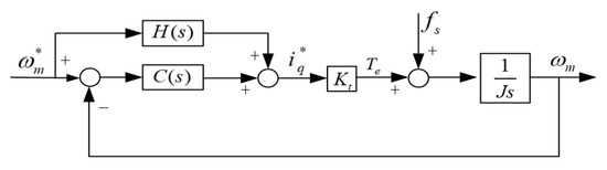
Figure 1.
The speed-loop two-degree-of-freedom controller with set-value feed-forward compensation.
The mathematical expression can be obtained from Figure 1.
where is the transfer function from to , is the transfer function from to . is the Laplace transformation of . is the Laplace transformation of . is the proportional–integral controller, which can be described as
where is the proportional coefficient, and is the integral coefficient. The following mathematical expression can be calculated:
where J is the moment of inertia of the permanent-magnetic synchronous motor. s is the Laplace operator. To eliminate step response overshoot in the system, is designed as a second-order low-pass filter.
where is is greater than 0 and less than 1. By combining (2) and (4), we get , which is the reference-value feed-forward compensation. The traditional PI controller with is a kind of two degree-of-freedom controller, which can be named a P-PI controller. Then we can calculate and according to the parameters of the permanent magnetic synchronous motor. By combining (3) and (4), we can obtain the following results:
Seen from (6) and (7), the tracking performance is determined by parameters , , and . However, the disturbance rejection performance is influenced by parameters , . If we first set the tracking performance, the disturbance rejection performance is fixed. If we first set the disturbance rejection performance, we can affect the tracking performance by changing . Thus, the parameter tuning of the 2-DoF controller described by (6) and (7) is sequential.
In addition, the P-PI controller can reject the disturbance described in (6) and (7) caused by load torque to a certain extent. But it is a passive disturbance rejection method. In order to enhance the disturbance rejection ability, we should use other methods, such as linear extended state observer (LESO). Linear extended state observer (LESO) can observe and compensate for disturbances, and the disturbance originates from sudden load torque, friction torque. However, if the LESO is inadequately designed, it can degrade the performance of the P-PI controller compared to its standalone version. To enhance both tracking and disturbance rejection capabilities in permanent-magnet synchronous motor systems, the meticulous design of the P-PI controller with LESO is crucial, making this research highly significant. Therefore, the integration of LESO into the P-PI controller is a complex task. The subsequent section will elaborate on the design aspects of the P-PI controller with LESO. For the 2-DoF controller called a P-PI controller with LESO, the parameter setting sequence for disturbance performance and tracking performance can be adjusted according to the actual situation.
3. The Design of P-PI with LESO
The mathematical representation of the permanent-magnet synchronous motor is presented as follows:
where is the nominal value of J, and is the nominal value of . Define , where is the nominal value of . B is the friction coefficient of the permanent-magnetic synchronous motor. We define , and is the total disturbance of the speed loop. Then, we treat as a new state variable. The state-space model is derived as follows:
where h is the derivative of . The linear extended state observer for Equation (8) is constructed as follows:
where and are the estimated values of and , respectively. and are the gain coefficients of the LESO. The disturbance performance of the system can be further improved by compensating for the disturbance observation value of the linear extended state observer using the output of the two-degree-of-freedom P-PI controller. The speed loop controller can be designed as P-PI controller with LESO, which is shown in Figure 2.
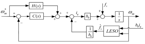
Figure 2.
Speed loop with 2-DoF P-PI-LESO.
By observing Figure 3, we can obtain the following transfer function:
where , and . Equations (11) and (12) can be represented as follows:
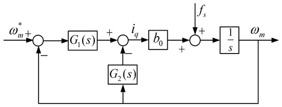
Figure 3.
Block diagram of equivalent structure of speed loop.
By observing Equations (6) and (13), the tracking performance of our improved two-degree-of-freedom P-PI controller with LESO is the same as the traditional 2-DoF P-PI controller. By observing Equations (7) and (14), our improved 2-DoF P-PI controller with LESO has more parameters that can be used to adjust the disturbance rejection element than the traditional 2-DoF P-PI controller. Compared to the traditional 2-DoF P-PI controller, fewer parameters are couple. The parameters of our proposed improved 2-DoF P-PI controller with LESO can be tuned with the following steps: Firstly, the P-PI parameters of 2-DoF controller can be set to perform the tracking of a reference signal, and then the bandwidth of the linear extended state observer can be adjusted to control the disturbance rejection performance.
The specific criteria for the parameter settings are as follows: Increasing leads to a faster system response and stronger disturbance rejection performance, but it decreases the stability margin. Increasing results in smoother speed waveforms, but it reduces the disturbance rejection performance. is utilized to eliminate speed overshoot, and increasing its value accelerates the dynamic response speed while decreasing the relative margin. Raising enhances the accuracy of disturbance estimation of the extended state observer, but higher observer bandwidth amplifies high-frequency noise and reduces stability.
4. Stability Analysis of 2-DoF Controller
The Laplace transform of (10) is as follows:
where is the Laplace transformation of , and is the Laplace transformation of .
The transfer function from the total disturbance to the feedback value and control input can be obtained by (15)
We define and , where is the observer bandwidth in [25]. We assume that and , which can guarantee the stability of the ESO.
(16) can be represented as follows:
Then, we get
where
According to (19) and (20), we can obtain the equivalent block diagram of 2-DoF control structure of speed loop of PMSM, as shown in Figure 3.
According to Figure 3, the open loop transfer function of the speed loop is as follows:
In (21), the stability of 2-DoF control structure of speed loop is affected by parameters , and . Given and , Nyquist curves results are shown in Figure 4, where , and .
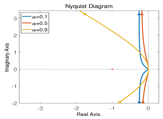
Figure 4.
Nyquist curves for different .
If fixing and , the Nyquist analysis is as demonstrated in Figure 5 for three different values of .
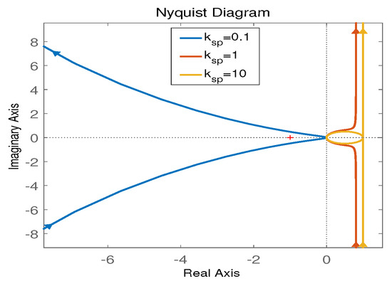
Figure 5.
Nyquist curves for different .
When and , we can generate Nyquist curves as shown in Figure 6 by changing .
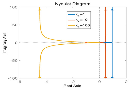
Figure 6.
Nyquist curves obtaining by changing .
Seen from the above three figures, all the Nyquist results are not bounded by ; thus, the system is stable and robust to these parameter changes.
5. Simulation Results and Analysis
To evaluate the controller performance of PI, P-PI, and P-PI-LESO, we present simulation results conducted in the MATLAB/Simulink environment.
In order to compare the performance of PI, 2-DOF P-PI, 2-DOF P-PI-LESO, we simulated the corresponding speed controllers. For PI controller, and . For 2-DOF P-PI, , , and . For 2-DOF P-PI-LESO, , , , and . Figure 7 depicts the speed response under no-load conditions. The implementation of a PI controller in the speed loop results in overshoot, with an overshoot value exceeding the reference by 363 r/min. However, utilizing a 2-DOF P-PI or 2-DOF P-PI-LESO can effectively eliminate this overshoot caused by the PI controller.
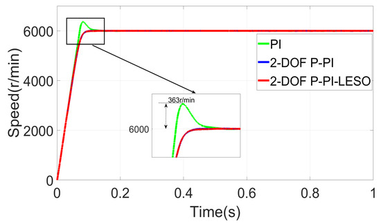
Figure 7.
Speed response under no-load conditions.
The simulation of motor starting with load is illustrated in Figure 8. Both Figure 8 and Figure 7 exhibit a similar phenomenon, demonstrating a decrease in the overshoot value of the PI controller. Upon careful examination of Figure 7 and Figure 8, it can be concluded that the incorporation of a linear extended state observer into the P-PI controller does not compromise the tracking performance of the speed loop.
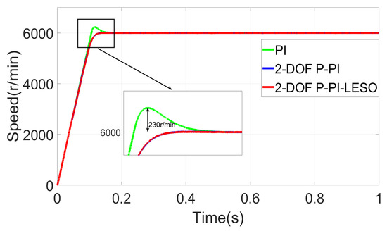
Figure 8.
Speed response under load condition.
The robustness analysis in Figure 9 reveals that the P-PI-LESO exhibits superior robustness compared to the PI, P-PI, and P-PI-LESO controllers. Additionally, Figure 10 presents quantized results obtained using integral time absolute error (ITAE), which further confirms the exceptional control performance of P-PI-LESO over PI, P-PI, and P-PI-LESO.
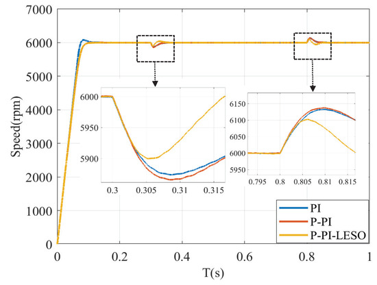
Figure 9.
Speed response under load disturbance.
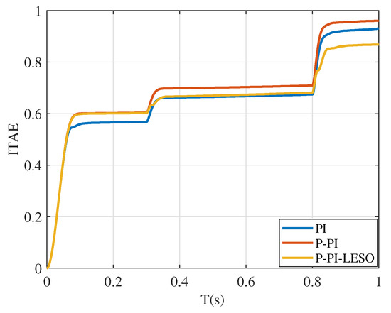
Figure 10.
Speed response under load disturbance using ITAE.
6. Experimental Results and Analysis
The effectiveness of the designed speed controller was further validated through experimentation on a permanent-magnet synchronous motor control system, as illustrated in Figure 11, which have been developed by Dalian University of Technology. The experimental setup primarily comprised a motor, a generator, a high-performance motor controller, a data acquisition upper computer, and a generator controller.
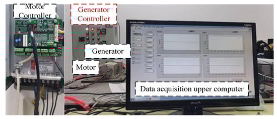
Figure 11.
Experimental platform for permanent-magnet synchronous motor control system.
6.1. Tracking Performance Test Verification
In Section 6.1, given that , are constant, we aim to enhance tracking performance by tuning parameter in Figure 12. When , are constant, we aim to enhance tracking performance by tuning parameter in Figure 13. When , are constant, we aim to enhance tracking performance by tuning the parameter in Figure 14.
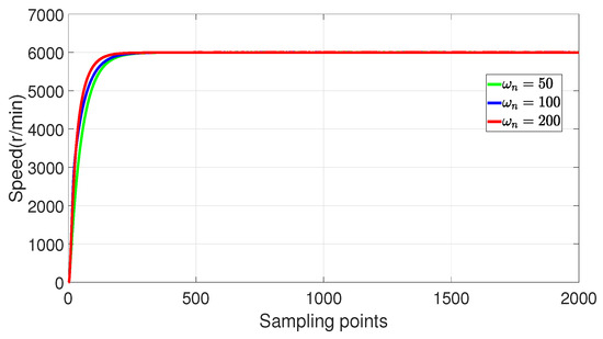
Figure 12.
Experimental verification of tracking performance of 2-DoF P-PI-LESO by changing .
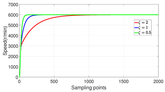
Figure 13.
Experimental verification of tracking performance of 2-DoF P-PI-LESO when changing .
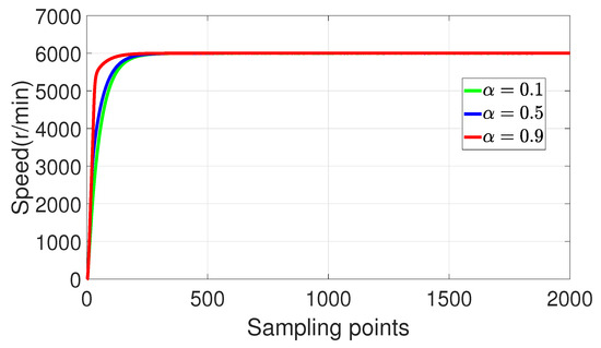
Figure 14.
Experimental verification of tracking performance of 2-DoF P-PI-LESO when changing .
Firstly, the impact of the parameters of the proposed two-degree-of-freedom P-PI linear extended state observer (2-DoF P-PI-LESO) on the performance of speed controller was experimentally validated. A PI controller was employed for the current controller, while a 2-DoF P-PI-LESO was utilized for the speed controller. The reference speed value was set at 6000r/min, and, under no-load conditions, variations in , and were investigated.
By observing Figure 12, increasing the value of can reduce the speed response time and enhance the tracking performance of the speed controller for PMSM. The examination of Figure 13 reveals that an increase in the value of results in a heightened speed response time and a prolonged speed adjustment time. The increase in the value of observed in Figure 14 leads to a reduction in speed response time, thereby enhancing its capability to track reference speed.
The tracking performance of the speed loop was then verified using a PI controller, a two-degree-of-freedom P-PI controller, and a 2-DoF P-PI-LESO (Dalian University of Technology, Dalian, China). The reference value for the speed was set at 6000 r/min. Experimental results of these controllers are presented in Figure 15. Upon observing Figure 15, it can be seen that there is step response overshoot when using the PI controller in the speed loop. However, this overshoot is eliminated when employing the two-degree-of-freedom P-PI controller and the 2-DoF P-PI-LESO, indicating that these controllers effectively eliminate step response overshoot. Furthermore, since the speed response curves of both the two-degree-of-freedom P-PI controller and the 2-DoF P-PI-LESO coincide completely, it can be concluded that the linear extended state observer does not affect the tracking performance of the speed controller.
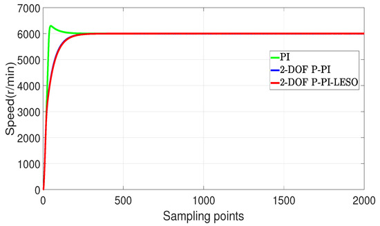
Figure 15.
The speed loop for three different controllers in speed response.
6.2. Experimental Verification of Load Disturbance
Firstly, the influence of each parameter of the 2-DoF P-PI-LESO on the disturbance rejection performance of the speed loop was verified. The given speed was set at 6000 r/min, and a load equivalent to 15% of rated torque was introduced as a disturbance. The experiments in Figure 16, Figure 17, Figure 18 and Figure 19 were conducted by varying the values of , , , and .
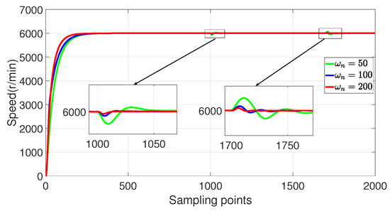
Figure 16.
Experimental verification of disturbance rejection performance of 2-DoF P-PI-LESO for different .
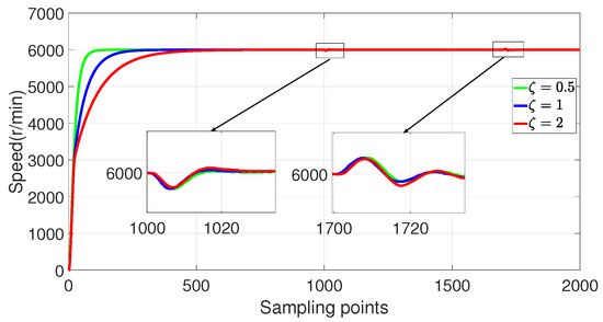
Figure 17.
Experimental verification of disturbance rejection performance verification of 2-DoF P-PI-LESO for different .
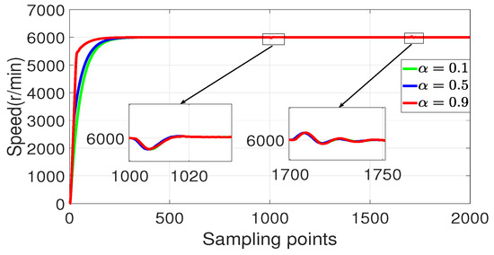
Figure 18.
Experimental verification of disturbance rejection performance of 2-DoF P-PI-LESO for different .
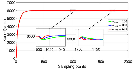
Figure 19.
Experimental verification of disturbance rejection performance of 2-DoF P-PI-LESO for different .
By observing Figure 16, it can be seen that increasing leads to smaller speed drops and rises after loading and unloading, as well as shorter recovery time to reach the reference speed. Therefore, increasing enhances the disturbance rejection performance of the speed controller.
By observing Figure 17, the time for feedback tracking of the reference speed increases when increases.
By observing Figure 18, the time for the feedback tracking of the reference speed increases when decreases. The speed curve is basically unchanged, which indicates that the disturbance rejection performance is independent of .
By observing Figure 19, it is evident that an increase in leads to a reduction in the speed drop and a rise in amplitude after loading and unloading, as well as a shorter recovery time to the reference speed.
The disturbance rejection performance of the speed loop is compared among a PI controller, a two-degree-of-freedom P-PI controller, and a 2-DoF P-PI-LESO. The given speed was set at 6000 r/min, with loading and unloading torque of 15% of the rated value. The experimental results are depicted in Figure 20. As shown in Figure 20, when employing the PI and P-PI controllers in the speed loop, the speed decreases by 38 r/min upon loading and increases by 40 r/min after unloading; moreover, it takes considerable time to recover to the desired speed. The corresponding outcomes are also presented in Table 1.
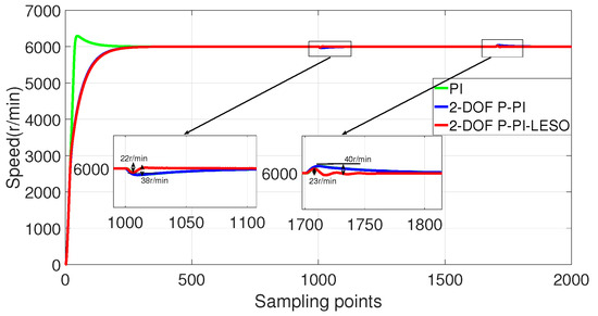
Figure 20.
Experimental verification of the disturbance rejection performance of the speed loop for three different controllers.

Table 1.
Experimental verification of the disturbance rejection performance of the speed loop for three different controllers.
The speed loop employs a 2-DoF P-PI-LESO, as shown in Figure 20. When the load torque is loaded, the speed decreases by approximately 22 r/min; conversely, when the load torque is removed, the speed increases by about 23 r/min. Moreover, the speed quickly recovers to its desired value. Hence, it can be inferred that the adoption of a linear extended state observer significantly enhances disturbance rejection performance. Consequently, the proposed 2-DoF P-PI-LESO exhibits commendable tracking and disturbance rejection capabilities.
7. Conclusions
For the traditional one-degree-of-freedom controller, there is a trade-off between the tracking performance and disturbance rejection performance. The traditional two-degree-of-freedom controller can guarantee disturbance rejection and tracking simultaneously, with one tracking channel and one disturbance rejection channel. To overcome the limitations of the one-degree-of-freedom controller and the traditional two-degree-of-freedom controller, an improved two-degree-of-freedom controller is designed for the permanent-magnet synchronous motor (PMSM) speed regulation system to be used in electric aircraft scenarios and PMSM control applications.
This paper presents the design of a novel two-degree-of-freedom speed controller for PMSMs, incorporating three key elements: a set-value feed-forward method, proportional–integral feedback, and extended state observer disturbance compensation. Experimental results demonstrate that the proposed controller overcomes the limitations of both one-degree-of-freedom and traditional two-degree-of-freedom controllers. Moreover, it effectively eliminates overshoot in comparison to the conventional PI controller without compromising disturbance rejection performance. The experimental findings validate the excellent tracking and disturbance rejection capabilities of the proposed two-degree-of-freedom controller, abbreviated as P-PI-LESO.
Author Contributions
Conceptualization, C.H. and K.L.; methodology, K.L. and P.L.; software, K.L.; validation, K.L., P.L., Y.G. and J.W.; formal analysis, P.L. and C.H.; investigation, P.L.; resources, C.H.; data curation, P.L.; writing—original draft preparation, K.L.; writing—review and editing, J.W. and Y.G.; visualization, J.W.; supervision, P.L.; project administration, P.L.; funding acquisition, P.L. and C.H. All authors have read and agreed to the published version of the manuscript.
Funding
This work was partly supported by the National Natural Science Foundation of China under Grant 62203085. And this work was also support by the Natural Science of Foundation of Fujian Province, China under Grant 2022J01808.
Data Availability Statement
The data presented in this study are available on request from the corresponding author. The data are not publicly available due to project data restriction.
Conflicts of Interest
The authors declare no conflicts of interest.
References
- Wheeler, P.; Bozhko, S. The More Electric Aircraft: Technology and challenges. IEEE Electrif. Mag. 2014, 2, 6–12. [Google Scholar] [CrossRef]
- Parancheerivilakkathil, M.S.; Pilakkadan, J.S.; Ajaj, R.M.; Amoozgar, M.; Asadi, D.; Zweiri, Y.; Friswell, M.I. A review of control strategies used for morphing aircraft applications. Chin. J. Aeronaut. 2024, 37, 436–463. [Google Scholar] [CrossRef]
- Samad, T. A Survey on Industry Impact and Challenges Thereof [Technical Activities]. IEEE Control Syst. Mag. 2017, 37, 17–18. [Google Scholar] [CrossRef]
- Errouissi, R.; Al-Durra, A.; Muyeen, S.M. Experimental Validation of a Novel PI Speed Controller for AC Motor Drives With Improved Transient Performances. IEEE Trans. Control Syst. Technol. 2018, 26, 1414–1421. [Google Scholar] [CrossRef]
- Dong, Z.; Yu, Y.; Li, W.; Wang, B.; Xu, D. Flux-Weakening Control for Induction Motor in Voltage Extension Region: Torque Analysis and Dynamic Performance Improvement. IEEE Trans. Ind. Electron. 2018, 65, 3740–3751. [Google Scholar] [CrossRef]
- Wang, W.; Liu, C.; Liu, S.; Song, Z.; Zhao, H.; Dai, B. Current Harmonic Suppression for Permanent-Magnet Synchronous Motor Based on Chebyshev Filter and PI Controller. IEEE Trans. Magn. 2021, 57, 8201406. [Google Scholar] [CrossRef]
- Tursini, M.; Parasiliti, F.; Zhang, D. Real-time gain tuning of PI controllers for high-performance PMSM drives. IEEE Trans. Ind. Appl. 2002, 38, 1018–1026. [Google Scholar] [CrossRef]
- Umeno, T.; Hori, Y. Robust speed control of DC servomotors using modern two degrees-of-freedom controller design. IEEE Trans. Ind. Electron. 1991, 38, 363–368. [Google Scholar] [CrossRef]
- Loh, P.C.; Pang, G.H.H. Flux-based two-degrees-of-freedom algorithm for three-phase electronic converter control. IEEE Power Electron. Lett. 2005, 3, 89–91. [Google Scholar] [CrossRef]
- Chen, P.; Luo, Y. A Two-Degree-of-Freedom Controller Design Satisfying Separation Principle with Fractional-Order PD and Generalized ESO. IEEE ASME Trans. Mechatronics 2022, 27, 137–148. [Google Scholar] [CrossRef]
- Huang, J.; Zhang, Z.; Han, J.; Jiang, W. Dynamic Performance Improvement for Permanent Magnet Generator System Using Current Compensating Method With Two-Degrees-of-Freedom Control. IEEE Trans. Ind. Electron. 2021, 68, 2823–2833. [Google Scholar] [CrossRef]
- Hussain, H.A. Tuning and Performance Evaluation of 2-DoF PI Current Controllers for PMSM Drives. IEEE Trans. Transp. Electrif. 2021, 7, 1401–1414. [Google Scholar] [CrossRef]
- Li, Z.; Zhang, W.; Liu, G.; Wang, B.; Zhang, Y. A novel Integral-Proportional (I-P) speed controller in PMSM motor drive. In Proceedings of the 11th World Congress on Intelligent Control and Automation, Shenyang, China, 29 June–4 July 2014; pp. 4236–4241. [Google Scholar] [CrossRef]
- Apte, A.; Thakar, U.; Joshi, V. Disturbance observer based speed control of PMSM using fractional order PI controller. IEEE CAA J. Autom. Sin. 2019, 6, 316–326. [Google Scholar] [CrossRef]
- Yuan, L.; Jiang, Y.; Xiong, L.; Wang, P. Sliding Mode Control Approach with Integrated Disturbance Observer for PMSM Speed System. CES Trans. Electr. Mach. Syst. 2023, 7, 118–127. [Google Scholar] [CrossRef]
- Guo, X.; Huang, S.; Peng, Y.; Lu, K.; Huang, S.; Luo, D.; Wu, X. An Improved Integral Sliding Mode Control for PMSM Drives Based on New Variable Rate Reaching Law with Adaptive Reduced-order PI Observer. IEEE Trans. Transp. Electrif. 2023, 9, 4503–4516. [Google Scholar] [CrossRef]
- Dong, N.; Li, X.; Chen, Z. Research on two-degree-of-freedom PID controller of permanent magnet synchronous motor based on fuzzy inference. In Proceedings of the 2017 20th International Conference on Electrical Machines and Systems (ICEMS), Sydney, NSW, Australia, 11–14 August 2017; pp. 1–6. [Google Scholar] [CrossRef]
- Pan, Z.; Dong, F.; Zhao, J.; Wang, L.; Wang, H.; Feng, Y. Combined Resonant Controller and Two-Degree-of-Freedom PID Controller for PMSLM Current Harmonics Suppression. IEEE Trans. Ind. Electron. 2018, 65, 7558–7568. [Google Scholar] [CrossRef]
- Xue, W.; Bai, W.; Yang, S.; Song, K.; Huang, Y.; Xie, H. ADRC With Adaptive Extended State Observer and its Application to Air Fuel Ratio Control in Gasoline Engines. IEEE Trans. Ind. Electron. 2015, 62, 5847–5857. [Google Scholar] [CrossRef]
- Bai, C.; Yin, Z.; Luo, J.; Luo, P.; Liu, J. Robust Composite Finite-Time Convergent Speed Control of Induction Machine Based on Multiple Sources Disturbance Estimation Technology Generalized Proportional Integral Observer. IEEE J. Emerg. Sel. Top. Power Electron. 2022, 10, 6160–6170. [Google Scholar] [CrossRef]
- Nguyen, T.H.; Nguyen, T.T.; Nguyen, V.Q.; Le, K.M.; Tran, H.N.; Jeon, J.W. An Adaptive Sliding-Mode Controller With a Modified Reduced-Order Proportional Integral Observer for Speed Regulation of a Permanent Magnet Synchronous Motor. IEEE Trans. Ind. Electron. 2022, 69, 7181–7191. [Google Scholar] [CrossRef]
- Lin, P.; Sun, X.M.; Fei, Z. A Generalized Interpretation of Three Types of Disturbance-Based Controllers for Perturbed Integral Systems in Frequency Domain. IEEE Trans. Circuits Syst. II Express Briefs 2021, 68, 1328–1332. [Google Scholar] [CrossRef]
- Tang, M.; Lau, V.K.N. Decentralized Event-Triggered Scheduling and Control for Multiagent Linear Systems Over Wireless Interference Channels. IEEE Trans. Control Netw. Syst. 2022, 9, 1348–1361. [Google Scholar] [CrossRef]
- Xi, J.; Dong, Z.; Ding, Y.; Liu, P.; Ding, H. An adaptive 2-DoF P-PI controller based on an improved just-in-time learning technique for ultra-low-velocity linear stages driven by PMLSMs. Precis. Eng. 2018, 52, 392–406. [Google Scholar] [CrossRef]
- Gao, Z. Scaling and bandwidth-parameterization based controller tuning. In Proceedings of the 2003 American Control Conference, 2003, Denver, CO, USA, 4–6 June 2003; Volume 6, pp. 4989–4996. [Google Scholar] [CrossRef]
Disclaimer/Publisher’s Note: The statements, opinions and data contained in all publications are solely those of the individual author(s) and contributor(s) and not of MDPI and/or the editor(s). MDPI and/or the editor(s) disclaim responsibility for any injury to people or property resulting from any ideas, methods, instructions or products referred to in the content. |
© 2025 by the authors. Licensee MDPI, Basel, Switzerland. This article is an open access article distributed under the terms and conditions of the Creative Commons Attribution (CC BY) license (https://creativecommons.org/licenses/by/4.0/).