Abstract
This study aims to develop an event-triggered control strategy of grid-connected inverters, based on the linear parameter-varying (LPV) modeling approach. Regarding the changes in grid voltage, filter capacitance and inductance, and random electromagnetic interference, a stochastic LPV model for three-phase two-level inverters is established. To reduce computation burden, an event trigger with a continuous-time form is adopted to derive the state feedback controller for the LPV plant. Unlike the existing common approach to dealing with event-triggered mechanisms, a predesignated event-triggering threshold is used to determine the triggering instant of the event condition. Using parameter-dependent Lyapunov functions, sufficient conditions reliant on parameters are introduced. Based on the derived conditions, the corresponding event-triggered controllers are engineered to ensure uniform ultimate bounded stability for the resulting event-triggered LPV inverter system subject to exogenous disturbance. The simulation results are presented to confirm the efficacy of the proposed methods.
1. Introduction
Grid-connected inverters are active front ends that connect power sources, such as wind-turbine generators, PV panels, energy storage systems, etc., to the utility grid. Inverter control is normally implemented by a digital microprocessor, which turns on/off the power switches to generate the required active/reactive power. With the increase in control algorithm complexity and switching frequency, the microprocessor faces a greater computational burden; meanwhile, there is more switching loss and the switch span is reduced. To target this problem, researchers have proposed event-triggered control. Event-triggered control implements control action when a certain event occurs, rather than periodically as in traditional digital control systems [1,2]. This feature saves energy, lowers communication, and reduces the computational burden of the control system.
There are some studies on event-triggered control in relation to power converters, but they mainly focus on DC/DC converters. For buck converters, the event-triggered auto-disturbance-rejection control strategy has been proposed, and an extended state observer is adopted to track system state and external interference and update the control signal when the estimation error reaches the limit [3]; in [4], the authors design a proportional–integral observer to deal with the uncertainty of mismatch and external disturbances with continuous derivatives. The above researches have obtained necessary criteria for guaranteeing constrained dynamic stability within the system’s theoretical framework, and the validity of the theory has been experimentally verified in buck converters. An event-triggered model predictive control system based on a finite-control-set model prediction method is firstly proposed for buck converters in [5], where the state error modulus is used as a triggering condition. A boost converter is treated as a switching model, and an event-triggered control method is designed to stabilize a linear switching system in [6]; on this basis, an event-triggered control method for a networked linear switching system is further proposed in [7]. Event-triggered sliding-mode control is applied to a buck converter in [8], which greatly reduces the switching frequency of the converter (by about 10 times). Meanwhile, it maintains almost the same control performance as in non-event-triggered control.
Linear parameter-varying (LPV) systems are modeled with temporal change parameters; they have the form of linear systems but includes time-varying uncertainties [9]. Due to this feature, LPV systems are popular in theoretical research and practical engineering, as the well-developed linear system theories can be used. For example, there are theoretical studies that address analysis and synthesis issues, robust filter design formulations, defect diagnosis and localization [10,11], etc. In existing engineering research, an LPV model has been established for lithium-ion batteries to enhance the assessment accuracy of peak-power evaluation under conditions of battery aging [12], an LPV framework has been adopted for a four-wheeled mobile robot to track its trajectory [13], and an uncertain robot system is regulated using an LPV-based control strategy incorporating sliding-mode techniques [14].
In contemporary system dynamics, stochastic systems have emerged as critical tools for analyzing probabilistic behaviors inherent in electromechanical actuators, renewable energy networks, and cellular regulatory pathways. During the last few decades, research has focused on stabilization and filtering problems for stochastic systems. For stabilization problems, stochastic stability analysis and control have been carried out and implemented in secondary frequency regulation for islanded microgrids [15], and in nonlinear systems, the issue of input-to-state stability being subject to stochastic impulsive effects has received systematic investigation [16]. Regarding filtering problems, the recursive estimation issue for specific uncertain random systems incorporating amplify-and-forward relaying techniques were investigated in [17], the decentralized robust filtering problem for randomly switched systems with communication delays under sensor measurement fading conditions was systematically studied in [18]. With the development of networked control, the event-triggering mechanism has been considered in controller design for stochastic systems. For example, an analysis of performance and mean-square exponential stability in discrete-time randomly switched hybrid systems within an event-triggered framework was conducted in [19]; in addition, under stochastic transmission protocols, an event-triggered control challenge in a stochastic nonlinear system was systematically investigated [20].
Regarding grid-connected inverters, they need to deal with grid voltage variations (including magnitude and frequency), the filter capacitance and inductance changes caused by aging and temperature, and the stochastic electromagnetic noise in the environment. To solve these problems, this study develops a variable-threshold event-triggered control approach for grid-connected two-level three-phase inverters using an LPV model. Treated as stochastic excitation terms, stochastic electromagnetic noise processes are incorporated alongside time-variant modeling of filter capacitance, grid voltage, and inductive components. The aims of this paper are to (i) establish a systematic event-triggered control scheme for an LPV system subject to event-triggering conditions; (ii) provide a sufficient condition of stability, namely uniform ultimate bounded stability, fir the LPV system under external disturbance; (iii) grounded in the derived stability conditions, design event-triggered controller gains.
This paper proposes a new modeling method for grid-connected inverters. Unlike the traditional LPV method, this paper includes stochastic perturbations in the model. Moreover, to consider a networked control scenario, which is typical of modern grid control frames, the event-triggered method is introduced to the model, which has a lower computational cost than the continuous control method. This paper is organized as follows: The system overview and inverter modeling are discussed in Section 2. The main results are reported in Section 3, followed by simulation validation in Section 4. Section 5 concludes the paper.
2. Inverter Modeling and System Description
Figure 1 is the grid-connected inverter under investigation, which is of a two-level three-phase topology. To facilitate control design, the inverter is normally described within a synchronously rotating coordinate frame, as elaborated below [21]:
where is the DC power supply input, represents the frequency of the grid voltage, L signifies the filter inductance and r stands for its series resistance component, and the three-phase abc quantities are transformed into dq variables, i.e., the grid voltages are converted from , , and . originate from the transformation of grid currents via , , and , while the control-synthesized switching functions are ; subsequently, the switching signals , , and can be derived. To ensure adequate power delivery to the motor or grid, need regulation to specified setpoints. Figure 2 shows the control scheme of the event-triggered stochastic LPV inverter system, which is divided into four parts: (1) the stochastic LPV dynamical system of the inverter; (2) the event trigger (including the smart sensor and event detector); (3) the event-triggered controller; (4) the zero-order holder (ZOH).
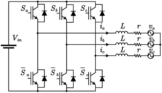
Figure 1.
Two-level three-phase inverter.
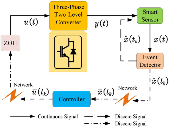
Figure 2.
Control scheme of event-triggered stochastic LPV inverter system.
2.1. Dynamical System
The stochastic LPV dynamical system of the inverter can be described in Itô’s form as follows:
where represents the dynamic state of the system; represents the dynamic coefficients r, L, and associated with the filtering inductance; denotes the control input; represents the gating matrix associated with L; is a disturbance input with the upper bound ; the controlled output is ; is a unidimensional Brownian motion meeting and ; and the vector parameter undergoes smooth temporal variation constrained within a bounded convex domain.
The parameter is unknown but observable in real time. In the rest of this paper, is used in place of for simplicity. Accordingly, the autonomous form of (2) adopts the following structure:
To analyze system stability and design controllers, the external disturbance term “” within Equation (2) is assumed to be negligible (zero), resulting in
The autonomous representation of the system (4) is given by
2.2. State Observer
The state is estimated using the measured output magnitude , based on the following state observer:
where denotes the observed state, and represents the parameter variable observer gain. Define as the estimation error; the dynamics of the estimation error are given by
2.3. Event Trigger
Normally, an event trigger includes two functional parts, i.e., an event generator and an event detector. The event detector continuously monitors the state of the dynamic system and checks if a predefined rule is violated, meaning that the event-triggering condition is satisfied. When this condition is achieved, then an event is generated by the event generator and an action is taken.
In this paper, an event is generated when the deviation between the present state and the most recently recorded state exceeds a certain threshold. If there occurs an event, the event generator transfers the latest sampled state to the event-triggered controller.
Let the sequence of event-triggering times be represented by with . Without loss of generality, assume the initial triggering time is .
The system state is sampled at each event time , and the subsequent triggering instant is computed based on
where the error , and denotes the predesignated event-triggering threshold.
2.4. Event-Triggered Controller
The feedback controller of an event-triggered state is employed in this paper. Once an event is generated, the system calculates the control input based on the sampled state
where refers to parameter-varying gain with suitable dimensions, and is a Bernoulli-distributed stochastic variable with
2.5. Zero-Order Holder
The actuation signal formulated in (9) undergoes parametric updates exclusively at the pre-computed triggering moment ; that is, the controller in (9) receives a sampled state which will not change until the next event happens at . Thus, to keep the continuity of the control signal, a zero-order holder (ZOH) should be embedded:
where is a Bernoulli-distributed stochastic variable with
Before delving deeper, several definitions and lemmas are first presented.
Definition 1.
System (5) achieves asymptotic mean-square stability if for arbitrary initial states .
Definition 2.
The stochastic LPV system (3) denotes robust stability with γ-disturbance attenuation in the sense when, for every and arbitrary parameter trajectories, the inequality presented below holds:
Lemma 1
([22]). (Itô’s formula) Let , where , be an n-dimensional stochastic process satisfying an Itô-type differential equation
where , , and . Accordingly, constitutes a real-valued Itô process, and its stochastic differential is formulated as
where represents the set of all functions with real values that possess continuous second derivatives in x and t. Assuming that , we define
Lemma 2.
Consider system (5) and assume the existence of a Lyapunov function satisfying
then for any non-zero state , system (5) exhibits asymptotic mean-square stability according to Definition 1.
3. Main Results
3.1. Event-Triggered Stabilization
Firstly, the designed conventional time-based control procedure is provided for the LPV system (5). The proposition below clarifies the stability condition of LPV system (5) based on Lyapunov stability theory.
Proposition 1.
Provided we have a set of parameter-dependent, continuously differentiable, symmetric positive definite matrices , it holds that all parameter trajectories satisfy
Consequently, system (5) is mean-square asymptotically stable.
Proof.
Adopt the following candidate Lyapunov function: . In accordance with Itô’s formula in Lemma 1,
where
Provided that the following inequality stands, then for any :
According to Lemma 2, system (5) is mean-square asymptotically stable. By virtue of the Schur complement, inequality (16) is equivalent to inequality (15). The proof is completed. □
Proposition 2.
Given parameter-dependent, continuously differentiable, symmetric positive definite matrices along with matrix , the following inequality holds for every parameter trajectory:
where
then under the controller and , system (4) is mean-square stable.
Proof.
For system (4) under the control law , the closed-loop representation of system is given by
Multiplying both sides of (16) by yields
where
Let , thus yielding
Therefore, (18) can be reformulated as
Applying the Schur complement, (19) is equivalent to
Considering the closed-loop system governed by the state feedback law , (20) is equivalent to
where
Let ; the result (21), i.e., for any , can be guaranteed by condition (17). The proof is completed. □
Propositions 1 and 2 present the conventional time-based controller design procedure for the considered LPV system without exogenous disturbance. According to the designed procedure, the subsequent theorem presents the event-based control scheme.
Firstly, During the time interval , from (8) and (9), the stochastic LPV system in closed-loop form (4) can be equivalently expressed as
where and .
On the basis of the resulting control system (22), the subsequent theorem formulates a stability criterion via the Lyapunov functional approach.
Theorem 1.
Consider a closed-loop system (22) with sampling instants determined by (8). For the parameter-varying gain matrices given by (17), assume the existence of a parameter-dependent family of symmetric positive definite matrices , which satisfy
consequently, the state expectation of system (22) exhibits global uniform ultimate boundedness and tends to converge within a bounded region.
where .
Proof.
Considering the candidate Lyapunov function , and assuming that the solution to (23) is the parameter-varying symmetric positive definite matrix , then according to Lemma 1, we determine that
Considering the sampling instants specified in (8), for any , holds. Thus, as long as , it follows that
thus, it follows that
Consider
Upon performing integration of both sides of (25) between 0 and t, and computing the expectation of the result, the following can be obtained:
which indicates that
Thus, it can be concluded that, as , the closed-loop system (22) is globally uniformly ultimately bounded, as guaranteed by [23], with state trajectories approaching the bounded region specified in (24). The proof is completed. □
Remark 1.
To solve in (23), Schur complement transformations should be operated to transform (23) into an LMI as follows:
where .
3.2. Event-Triggered Control
Similarly, the designed conventional time-based control procedure is firstly provided for an LPV system (3) in the following propositions for further synthesis of an event-triggered controller.
Proposition 3.
The stochastic LPV system (3) is robustly stabilized despite disturbance attenuation γ. Given the existence of a continuously differentiable, parameter-dependent family of symmetric positive definite matrices for all parameter trajectories, the inequality given below is satisfied:
where
Proof.
Set the candidate Lyapunov function to . Without loss of generality, suppose the initial state of the system is zero, i.e., , when . It follows from Itô’s formula that
Let
where with With the Schur complement, condition (26) guarantees that , and consequently, , meaning . Thus, (3) exhibits robust stability according to Definition 2. The proof is completed. □
Proposition 4.
Assume the existence of a parameter-dependent family of symmetric positive definite matrices, and ; the state feedback controller ensures the robust stabilization of the stochastic LPV system (2) with disturbance attenuation γ, where the following inequality is satisfied under all possible parameter evolutions:
where and .
Proof.
Take system (2) with , and replace in (26) with , with the congruence transformation matrix diag , and apply it to (26), thus obtaining
where . Let and define ; substituting these expressions into the transformed inequality yields (27), with . The proof is completed. □
To improve the feasibility of the LMIs in Propositions 3 and 4, slack matrices can be introduced, which leads to following proposition.
Proposition 5.
Assume the existence of a parameter-dependent family of symmetric positive definite matrices, and , and matrices and T, the state feedback controller ensures the robust stabilization of the stochastic LPV system (2) with disturbance attenuation γ, and (29) is satisfied for all parameter trajectories.
where and .
Proof.
First, the robust stability of the autonomous system (3) is established through a derived sufficient condition. Consider (30):
where is a continuous differentiable, parameter-dependent, symmetric positive matrix, and W is a general matrix of proper dimensions. We will demonstrate that if and W are feasible, under disturbance attenuation , system (3) is robustly stable.
Inequality (30) is equivalent to (31):
for which and , and the null spaces are, respectively,
Based on the Projection Lemma [24], it can be determined that
where . Inequality (32) can be transformed into (26) via Schur complement transformation, thereby demonstrating that (30) guarantees the robust stability of system (3).
Now, take (2) with , and replace in (30) with , followed by a congruence transformation via diag ; then, (33) can be obtained:
where Suppose matrices , , , and ; then, (29) is obtained, and . The proof is completed. □
Similarly to the modeled system (22), during the time span , based on (8) and (9), the stochastic LPV system in closed-loop form (2) can be rewritten as
where , .
Referencing the design procedure, the following theorem provides a uniformly ultimately bounded stability criterion for the resulting event-triggered control system (34). It provides a bounded region describing convergence for the overall event-based control system.
Theorem 2.
Take the closed-loop system (34) with sampling instants specified by (8). For the parameter-varying gain matrices given by (29), assuming the existence of a family of parameter-varying symmetric positive definite matrices that satisfy
the LPV stochastic system (34) exhibits robust stability with disturbance attenuation γ; furthermore, the state expectation satisfies global uniform ultimate boundedness and converges to the bounded region
where , and is the upper bound of external disturbance.
Proof.
With given by (29), the stability of the dynamical system is achieved. Next, we shall prove that the system states will converge to a bounded region. Considering the candidate Lyapunov function , it follows from Lemma 1 that
For every , holds; thus, it follows that
thus, it can be determined that
Consider
thus,
which indicates that
Thus, it can be seen that, as , the closed-loop system (34) is shown to be globally uniformly ultimately bounded. Additionally, the states converge to the bounded region specified in (36). The proof is completed. □
Remark 2.
To solve in (35), Schur complement transformations should be operated to transform (35) to an LMI as follows:
where .
4. Simulation Results
The simulation employs the grid and inverter parameters V, V, V, H, , and rad/s, which are typical values for grid-connected operation. The LPV inverter model (2) is characterized by the following matrices:
where the time-varying parameters and satisfy , , , and .
To carry out simulations, the basis functions are used to approximate the parameter-dependent matrices; therefore, , where represents the parameter-dependent matrices appearing in this paper. Therefore, to solve a matrix variable is to solve . The event-triggering threshold is set at .
Case i: Event-triggered Stabilization
Design an event-triggered controller that guarantees system (4) is asymptotically mean-square stable. Based on Theorem 1, it can be determined that
The obtained controller is as follows:
Throughout the time period , the control signal is
Set the initial state to . The state response of the closed-loop system is illustrated in Figure 3, from which it can be observed that the state converges to a bounded region. This means the system is stabilized with the event-triggered controller. The control input signal is shown in Figure 4, the triggering error norm is presented in Figure 5, and the intervals between consecutive events are shown in Figure 6.
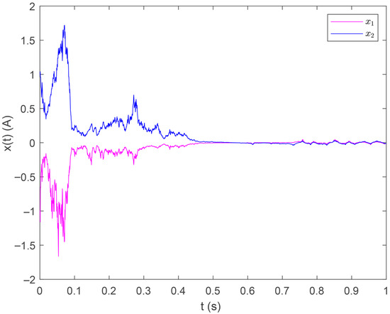
Figure 3.
State response under Case i.
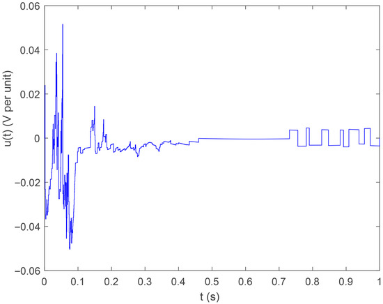
Figure 4.
Control input under Case i.
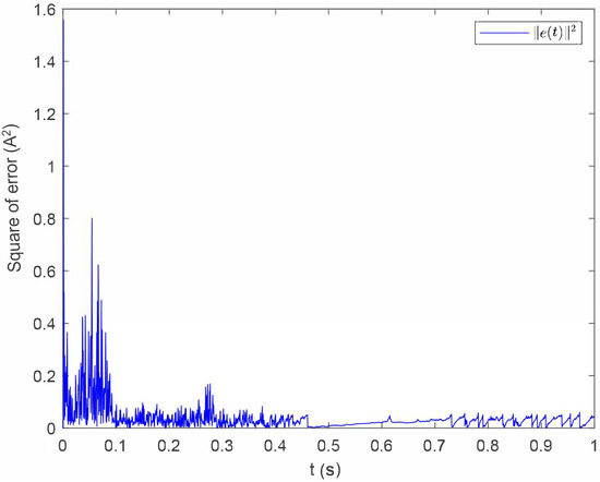
Figure 5.
Trajectory of under Case i.
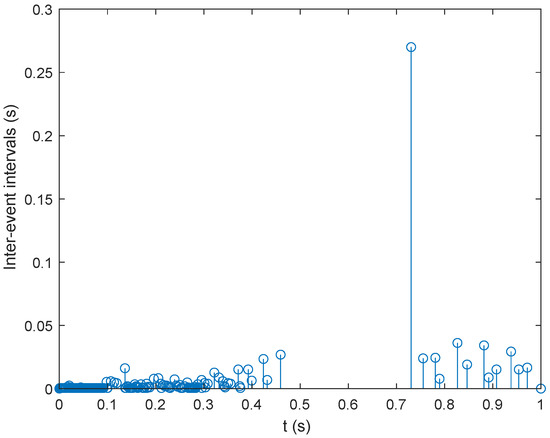
Figure 6.
Event intervals under Case i.
Case ii: Event-triggered Control
The disturbance signal is introduced.The design objective is to construct an event-triggered controller to stabilize system (2) and meet the disturbance attenuation criterion . According to Theorem 2, it can be determined that
thus, over the period , the control signal is
Set the initial state at . With this controller, the system is stabilized, as demonstrated in Figure 7. Figure 8 shows the control input signal. while Figure 9 and Figure 10 display the error norm and event intervals, respectively.
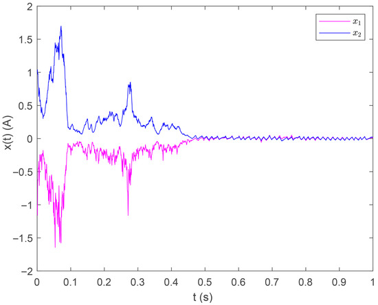
Figure 7.
State response under Case ii.
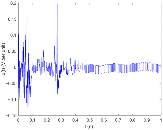
Figure 8.
Control input under Case ii.
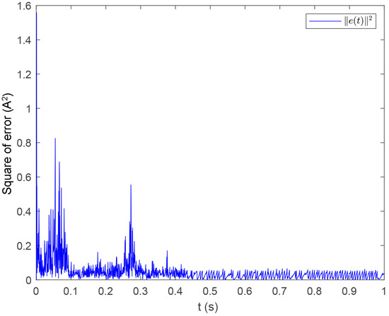
Figure 9.
Trajectory of under Case ii.
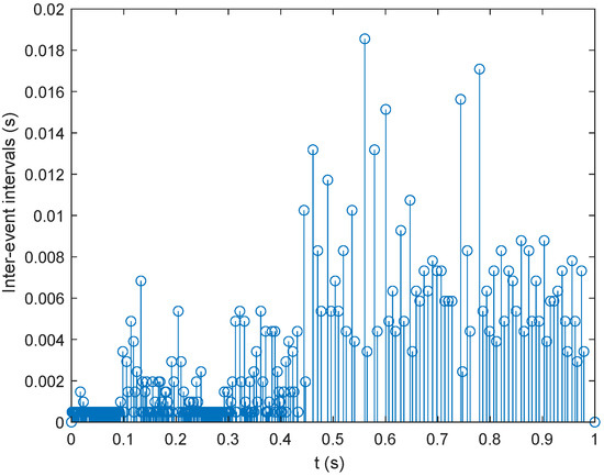
Figure 10.
Event intervals under Case ii.
5. Discussion
The aim of the simulation for Case i is to verify the effectiveness of the proposed event-triggered controller and the correctness of the theoretical deduction. The inverter states converge to equilibrium under the proposed controller, and the control signal is a discrete one, which complies with the event-triggering mechanism. Moreover, the average control interval is 0.04 s, which saves 400 control cycles for the 10 kHz digital control cycle. The aim of the simulation for Case ii is to further test the robustness of the system when disturbed by a time-varying signal. The simulation results show that the system stability is maintained, and the control output also follows a event-triggering pattern. In this case, the average control interval is 0.006 s, which saves 60 control cycles for the 10 kHz digital control cycle. Moreover, due to the disturbance, the event intervals are narrower.
6. Conclusions
An event-triggered controller for grid-connected inverters is designed within the frame of a linear parameter-varying (LPV) system, which takes into consideration the time-varying feature of inverter parameters and the stochasticity of electromagnetic noise. A stochastic LPV model for three-phase two-level inverters is established, for which an event trigger with a continuous-time form is designed with a predesignated event-triggering threshold. This mechanism is typical for modern grid control frames, and has a lower computational cost than the continuous control method. The sufficient conditions of the uniform ultimate bounded stability are obtained for the resulting event-triggered LPV system subject to exogenous disturbance. The simulation results show that the inverter system is stabilized, with minor performance degradation, while the computational burden and communication density are reduced.
Author Contributions
Conceptualization, W.L.; methodology, W.L.; validation, W.L., Z.Z. and Z.S.; formal analysis, J.Z.; investigation, W.L.; data curation, Z.S. and H.L.; writing—original draft preparation, W.L., Z.Z. and Z.S.; writing—review and editing, W.L. and Z.Z.; supervision, W.L. All authors have read and agreed to the published version of the manuscript.
Funding
This work is supported in part by the National Natural Science Foundation of China, under grant 62003114; the Provincial Natural Science Foundation of Heilongjiang, under grant LH2023F019; the China Postdoctoral Science Foundation, under grant 2020M681097; the Heilongjiang Postdoctoral Fund, under grant LBH-Z20134; the Fundamental Research Funds for the Central Universities, under grant HIT.NSFJG202207; and the National Key Laboratory of Laser Spatial Information Foundation, under grant LSI2025WDZC07.
Data Availability Statement
The original contributions presented in this study are included in the article. Further inquiries can be directed to the corresponding author.
Conflicts of Interest
The authors declare no conflicts of interest.
References
- Zhang, Y.; Wu, Z.-G.; Shi, P. Resilient Event-/Self-Triggering Leader-Following Consensus Control of Multiagent Systems Against DoS Attacks. IEEE Trans. Ind. Inform. 2023, 19, 5925–5934. [Google Scholar] [CrossRef]
- Zhou, J.; Xu, Y.; Sun, H.; Li, Y.; Chow, M.-Y. Distributed Power Management for Networked AC–DC Microgrids with Unbalanced Microgrids. IEEE Trans. Ind. Inform. 2020, 16, 1655–1667. [Google Scholar] [CrossRef]
- Sun, J.; Yang, J.; Li, S.; Zheng, W.X. Sampled-Data-Based Event-Triggered Active Disturbance Rejection Control for Disturbed Systems in Networked Environment. IEEE Trans. Cybern. 2017, 49, 556–566. [Google Scholar] [CrossRef] [PubMed]
- Yang, J.; Sun, J.; Zheng, W.X.; Li, S. Periodic Event-Triggered Robust Output Feedback Control for Nonlinear Uncertain Systems with Time-Varying Disturbance. Automatica 2018, 94, 324–333. [Google Scholar] [CrossRef]
- Wang, B.; Huang, J.; Wen, C.; Rodriguez, J.; Garcia, C.; Gooi, H.B.; Zeng, Z. Event-Triggered Model Predictive Control for Power Converters. IEEE Trans. Ind. Electron. 2020, 68, 715–720. [Google Scholar] [CrossRef]
- Ma, G.; Qin, L.; Liu, X.; Wu, G. Event-Triggered Output-Feedback Control for Switched Linear Systems with Applications to a Boost Converter. In Proceedings of the 2016 IEEE 11th Conference on Industrial Electronics and Applications (ICIEA), Hefei, China, 5–7 June 2016; pp. 2431–2436. [Google Scholar]
- Ren, H.; Zong, G.; Li, T. Event-Triggered Finite-Time Control for Networked Switched Linear Systems with Asynchronous Switching. IEEE Trans. Ind. Inform. 2018, 48, 1874–1884. [Google Scholar] [CrossRef]
- Rathore, N.; Fulwani, D. Event Triggered Control Scheme for Power Converters. In Proceedings of the IECON 2016—42nd Annual Conference of the IEEE Industrial Electronics Society, Florence, Italy, 23–26 October 2016; pp. 1342–1347. [Google Scholar]
- Yang, X.; Yin, S. Robust Global Identification and Output Estimation for LPV Dual-Rate Systems Subjected to Random Output Time-Delays. IEEE Trans. Ind. Inform. 2017, 13, 2876–2885. [Google Scholar] [CrossRef]
- Han, K.; Feng, J.; Zhao, Q. Robust Estimator-Based Dual-Mode Predictive Fault-Tolerant Control for Constrained Linear Parameter Varying Systems. IEEE Trans. Ind. Inform. 2021, 17, 4469–4479. [Google Scholar] [CrossRef]
- de Oliveira, M.S.; Pereira, R.L. LMI-Based Filter Design Conditions for Discrete-Time LPV Systems with Bounded Parameter Variation. IEEE Trans. Autom. Control 2021, 66, 910–915. [Google Scholar] [CrossRef]
- Hu, X.; Xiong, R.; Egardt, B. Model-Based Dynamic Power Assessment of Lithium-Ion Batteries Considering Different Operating Conditions. IEEE Trans. Ind. Inform. 2014, 10, 1948–1959. [Google Scholar] [CrossRef]
- Rotondo, D.; Puig, V.; Nejjari, F.; Romera, J. A Fault-Hiding Approach for the Switching Quasi-LPV Fault-Tolerant Control of a Four-Wheeled Omnidirectional Mobile Robot. IEEE Trans. Ind. Electron. 2015, 62, 3932–3944. [Google Scholar] [CrossRef]
- Incremona, G.P.; Ferrara, A.; Utkin, V.I. Sliding Mode Optimization in Robot Dynamics with LPV Controller Design. IEEE Control Syst. Lett. 2022, 6, 1760–1765. [Google Scholar] [CrossRef]
- Liu, S.; Hu, Z.; Wang, X.; Wu, L. Stochastic Stability Analysis and Control of Secondary Frequency Regulation for Islanded Microgrids Under Random Denial of Service Attacks. IEEE Trans. Ind. Inform. 2019, 15, 4066–4075. [Google Scholar] [CrossRef]
- Tang, Y.; Wu, X.; Shi, P.; Qian, F. Input-to-State Stability for Nonlinear Systems with Stochastic Impulses. Automatica 2020, 113, 108766. [Google Scholar] [CrossRef]
- Tan, H.; Shen, B.; Peng, K.; Liu, H. Robust Recursive Filtering for Uncertain Stochastic Systems with Amplify-and-Forward Relays. Int. J. Syst. Sci. 2020, 51, 1188–1199. [Google Scholar] [CrossRef]
- Chen, Y.; Wang, Z.; Yuan, Y.; Date, P. Distributed H∞ Filtering for Switched Stochastic Delayed Systems Over Sensor Networks with Fading Measurements. IEEE Trans. Cybern. 2020, 50, 2–14. [Google Scholar] [CrossRef]
- Liu, J.; Wu, L.; Wu, C.; Luo, W.; Franquelo, L.G. Event-Triggering Dissipative Control of Switched Stochastic Systems via Sliding Mode. Automatica 2019, 103, 261–273. [Google Scholar] [CrossRef]
- Liu, K.-Z.; Teel, A.R.; Sun, X.-M. Event-Triggered Nonlinear Systems with Stochastic Dynamics, Transmission Times, and Protocols. IEEE Trans. Autom. Control 2022, 67, 1973–1979. [Google Scholar] [CrossRef]
- Luo, W.; Vazquez, S.; Liu, J.; Gordillo, F.; Franquelo, L.G.; Wu, L. Control System Design of a Three-Phase Active Front End Using a Sliding-Mode Observer. IEEE Trans. Syst. Man Cybern. Syst. 2022, 52, 739–748. [Google Scholar] [CrossRef]
- Mao, X.; Yuan, C. Stochastic Differential Equations with Markovian Switching; Imperial College Press: London, UK, 2006. [Google Scholar]
- Corless, M.; Leitmann, G. Continuous State Feedback Guaranteeing Uniform Ultimate Boundedness for Uncertain Dynamic Systems. IEEE Trans. Autom. Control 1981, 26, 1139–1144. [Google Scholar] [CrossRef]
- Gahinet, P.; Apkarian, P. A Linear Matrix Inequality Approach to H∞ Control. Int. J. Robust Nonlinear Control 1994, 4, 421–448. [Google Scholar] [CrossRef]
Disclaimer/Publisher’s Note: The statements, opinions and data contained in all publications are solely those of the individual author(s) and contributor(s) and not of MDPI and/or the editor(s). MDPI and/or the editor(s) disclaim responsibility for any injury to people or property resulting from any ideas, methods, instructions or products referred to in the content. |
© 2025 by the authors. Licensee MDPI, Basel, Switzerland. This article is an open access article distributed under the terms and conditions of the Creative Commons Attribution (CC BY) license (https://creativecommons.org/licenses/by/4.0/).