Article

A Coordinated Neuro-Fuzzy Control System for Hybrid Energy Storage Integration: Virtual Inertia and Frequency Support in Low-Inertia Power Systems

by
Carlos H. Inga Espinoza
* and
Modesto T. Palma
National University of Engineering, Lima 15333, Peru
*
Author to whom correspondence should be addressed.
Energies 2025, 18(17), 4728; https://doi.org/10.3390/en18174728
Submission received: 5 August 2025 / Revised: 25 August 2025 / Accepted: 27 August 2025 / Published: 5 September 2025

Abstract

Energy policies and economies of scale have promoted the expansion of renewable energy sources, leading to the displacement of conventional generation units and a consequent reduction in system inertia. Low inertia amplifies frequency deviations in response to generation–load imbalances, increasing the risk of load shedding and service interruptions. To address this issue, this paper proposes a coordinated control strategy based on neuro-fuzzy networks, applied to a hybrid energy storage system (HESS) composed of batteries and supercapacitors. The controller is designed to simultaneously emulate virtual inertia and implement virtual droop control, thereby improving frequency stability and reducing reliance on spinning reserve. Additionally, a state-of-charge (SOC) management layer is integrated to prevent battery operation in critical zones, mitigating degradation and extending battery lifespan. The neuro-fuzzy controller dynamically coordinates the power exchange both among the energy storage technologies (batteries and supercapacitors) and between the HESS and the conventional generation unit, enabling a smooth and efficient transition in response to power imbalances. The proposed strategy was validated through simulations in MATLAB R2022b using a two-area power system model with parameters sourced from the literature and validated references. System performance was evaluated using standard frequency response metrics, including performance indicators (ITSE, ISE, ITAE and IAE) and the frequency nadir, demonstrating the effectiveness of the approach in enhancing frequency regulation and ensuring the operational safety of the energy storage system.

1. Introduction

Energy policies aimed at decarbonizing electricity production to reduce greenhouse gas emissions have accelerated the integration of renewable energy sources into modern power systems. As a consequence, conventional synchronous generators, which inherently provide rotational inertia, are being replaced by non-conventional generation units equipped with power electronic inverters [1]. This transition significantly reduces the total system inertia, impairing the grid’s ability to resist sudden frequency deviations caused by generation–load imbalances. Low-inertia systems are characterized by higher rates of change of frequency (ROCOFs) and deeper frequency nadirs, which may exceed operational thresholds and lead to under-frequency load shedding or even cascading outages [2]. These challenges are particularly pronounced in weak or isolated grids with high levels of renewable penetration. Recent studies have highlighted the urgent need for fast frequency support services and inertia emulation mechanisms to ensure system stability under these conditions [3,4,5]. Recent developments in virtual inertia control and virtual droop control applied to energy storage systems have demonstrated strong potential to enhance frequency stability in modern power grids. These strategies rely on advanced control architectures and dynamic responses that consider operational constraints such as the state of charge, enabling faster and more reliable support during power imbalances [6,7,8].
While the need for fast frequency response and virtual inertia support has become increasingly evident in low-inertia systems, renewable energy sources such as wind and solar still face important limitations that hinder their direct contribution to frequency regulation. Their power output is inherently variable and non-dispatchable, and their connection through power electronic inverters decouples them from the mechanical inertia traditionally provided by synchronous machines. In many emerging economies, regulatory frameworks prioritize investment in renewable technologies but often exclude these units from participating in frequency control services. In contrast, international standards and guidelines such as IEEE 1547 [9], ENTSO-E operational requirements [10], and NERC standards [11] emphasize the importance of integrating fast frequency response and active power support capabilities, particularly in low-inertia systems. These frameworks highlight the growing role of energy storage systems in maintaining grid stability under high-renewable-penetration scenarios. As a result, the burden of maintaining frequency stability falls on conventional power plants, which are responsible for providing both primary and secondary frequency regulation via spinning reserves. This issue has been widely discussed in recent review studies, which emphasize the need for flexible grid support strategies involving energy storage systems to compensate for the lack of inertial response in systems predominantly supplied by renewable energy sources [12]. To address this challenge, recent research has investigated control strategies that enable renewable energy plants to contribute more actively to system stability. For example, deloading techniques in wind farms reserve a portion of the available mechanical power to provide active power support during frequency deviations [13,14]. Similarly, battery energy storage systems (BESSs) have been deployed in solar and wind power plants to emulate virtual inertia and contribute to frequency regulation. These systems can be integrated at various points in the plant, such as within the back-to-back converter of a wind turbine [15,16] or through dedicated inverters connected to the point of common coupling [17].
Several authors have proposed the use of BESSs for both inertial and primary frequency response. In [18,19], virtual inertia control strategies for BESSs were introduced, while [2,20] examined their role in primary frequency regulation. Hybrid energy storage systems (HESSs), which combine batteries and supercapacitors, have also been investigated for this purpose. Studies such as [15,21,22] suggest that supercapacitors are well-suited for fast inertial response, whereas batteries are more appropriate for sustained primary frequency support. The benefits of coordinated action between both technologies to improve the frequency nadir and the rate of change of frequency (ROCOF) are highlighted in [23].
Regarding control methods for primary frequency regulation, one of the most commonly used strategies is virtual droop control, as proposed in [24,25,26]. However, this type of controller does not take into account the state of charge (SOC) of the energy storage system (ESS). Operating at a low SOC poses a risk, as reaching the lower limit can trigger a sudden shutdown of the BESS, potentially returning the power system to a state of generation–load imbalance. To address this issue, strategies have been proposed in [20,23,27] that reduce the output power as the SOC decreases. Nevertheless, these strategies often overlook the actual power level being supplied when defining the power reduction functions. A two-stage fuzzy logic controller for determining the reference power of distributed BESS units during primary frequency regulation was proposed in [28]. Moreover, recent reviews have highlighted the increasing importance of control strategies that are aware of the state of charge and capable of adapting in real time, particularly in hybrid configurations where the power flow between storage layers must be dynamically optimized to prevent over-discharge and ensure long-term system resilience [29].
Based on the reviewed literature, it is evident that most publications focus on enhancing specific aspects of the dynamic frequency response, such as inertial support or primary regulation, rather than proposing comprehensive and integrated solutions. Furthermore, most approaches consider the energy storage system (ESS) as an independent generation unit within the power system, rather than as a subsystem integrated into the conventional generation plant. This gap has also been acknowledged in recent review articles, which emphasize the lack of fully integrated control architectures that combine virtual inertia, state-of-charge management, and coordination with synchronous generation units [29]. This perspective overlooks the potential of using a HESS not only to meet the operational requirements established by local regulations, but also to generate economic benefits for conventional power plants. Such integration could motivate investment in HESS technologies without the need for regulatory mandates.
This paper proposes a coordinated control strategy based on neuro-fuzzy networks applied to a hybrid energy storage system (HESS) composed of batteries and supercapacitors. The controller is designed to emulate virtual inertia and implement primary frequency regulation while actively managing the SOC to prevent battery degradation. The proposed coordinated approach independently adjusts the reference power outputs of the supercapacitors and batteries within the HESS, depending on the specific stage of frequency regulation (inertial or primary) and the real-time state of charge of each storage element. This ensures proper allocation of fast-response power from supercapacitors and sustained power support from batteries, while coordinating with the conventional generation unit (CGU) to maintain system stability and efficiency.
The main contributions of this paper are as follows:
-
The design of a neuro-fuzzy controller applied to the HESS for providing virtual inertia and virtual droop control, considering the state of charge of the supercapacitors.
-
A control strategy for power transition based on SOC, which coordinates energy exchange between the HESS and the conventional generation unit (CGU), ensuring reliable and efficient energy dispatch.
The rest of the paper is organized as follows: Section 2 presents the modeling of the two-area power system and the energy storage components. Section 3 introduces the control architecture and strategies employed in each stage of frequency regulation. Section 4 discusses the simulation results and performance evaluation. Finally, Section 5 summarizes the main conclusions of the study.

2. System Modeling

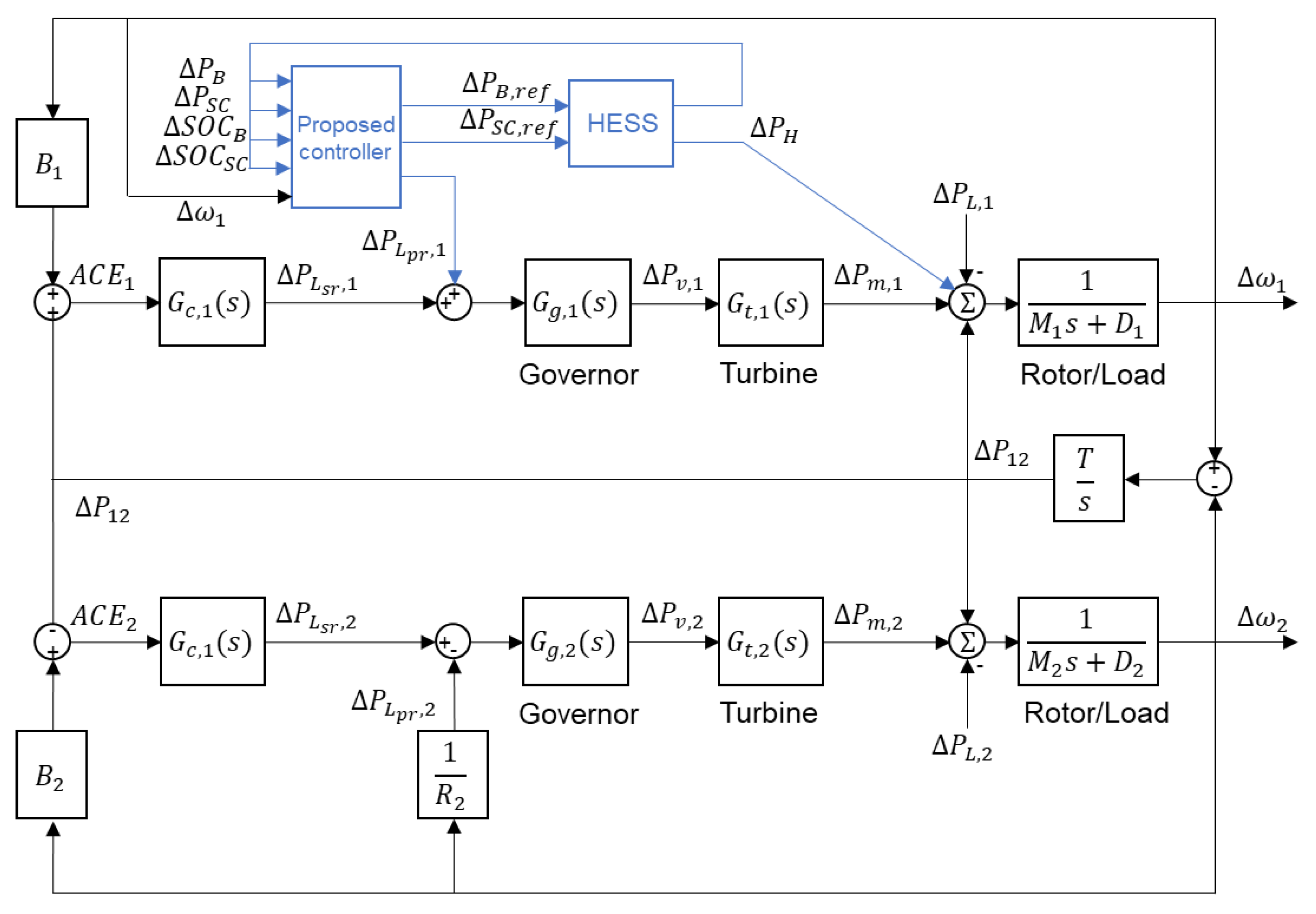
The two-area model has been widely used in numerous investigations to analyze the performance of control strategies in frequency regulation. This model consists of analyzing two generation units interconnected by a tie line, as shown in Figure 1. It considers the linear models of thermal power plants without overheating. Based on this, the dynamics of governors and turbines are represented in Equations (1) and (2), respectively. The swing equations of the frequency depend on the inertia of the system in each area, as defined in Equation (3), while the transfer power depends on the difference of the frequency between both areas, see Equation (4) [30].
G g , i s = P v , i ( s ) P L r e f , i ( s ) = 1 τ g , i s + 1
G t , i s = P m , i ( s ) P v , i ( s ) = 1 τ t , i s + 1
2 H i ω i ˙ = D ω + P m i + P R E R + P H P 12 P L , i
P 12 ˙ = T ( ω 1 ω 2 )
In the proposed model, the reference power for primary regulation is obtained through droop control, and the reference power for secondary regulation is defined with a PID controller, as indicated in Equations (5) and (6), respectively.
P L p r , i = 1 R i ω i
P L s r , i = K P , i A C E i + K I , i A C E i d t + K D d A C E 1 d t
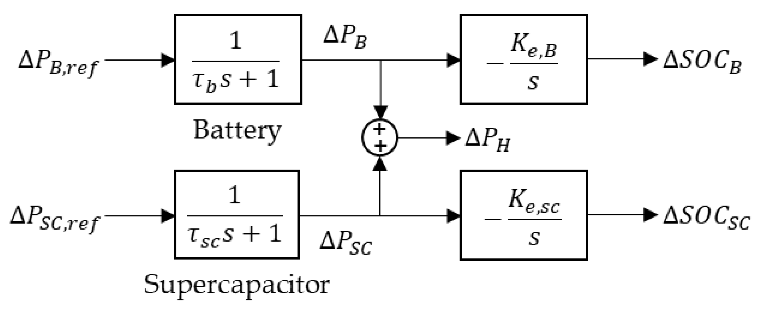
The HESS block diagram is shown in Figure 2. These are two systems that can be controlled independently, but with the restriction that the sum of the power from batteries and supercapacitors must not exceed the maximum power of the inverter. The transfer function of the power generated by the battery system taking into account a reference power is defined in Equation (7). In this expression, it can be seen that it is a first-order transfer function, in which the settling time will depend only on the time constant τ b [31].
G B s = P B ( s ) P B , r e f ( s ) = 1 τ b s + 1
The state of charge of the battery (SOC) represents the level of stored energy expressed in per-unit values. An SOC of 50% is considered the ideal operating condition, since it allows the storage element to both absorb and deliver energy during a frequency regulation event. Accordingly, the deviation of the SOC ( S O C ) is measured with respect to this 50% condition, as defined in Equations (8) and (9) [23].
S o C B s = K E , B s P B ( s )
K e , B = 1 3600 S B E B
Similarly, the transfer function of the power generated by the supercapacitors and the state of charge are defined in Equations (10)–(12) [23,31].
G S C s = Δ P S C s Δ P S C , r e f s = 1 τ s c s + 1
Δ S O C S C s = K e , S C s Δ P S C s
K e , S C = 1 3600 S S C E S C
Based on what was mentioned above, the equation of the states of the two-area system that includes a HESS in Area 1 is defined in Equation (13), where the state variables and inputs are presented in Equation (14) and the parameters of matrices A and B are shown with detail in Appendix A.
x = A x + B u + E w
x = Δ ω 1 Δ ω 2 Δ P v , 1 Δ P m , 1 Δ P v , 2 Δ P m , 2 Δ P 12 Δ P L s r , 1 Δ P L s r , 2 Δ P B Δ P S C Δ S O C B Δ S O C S C T u = Δ P L p r , 1 Δ P L p r , 2 Δ P B , r e f Δ P S C , r e f T w = Δ P L , 1 Δ P L , 2 Δ P R E R , 1 Δ P R E R , 2 T

3. Control Strategies

In this section, the control strategies applied to BESSs and HESSs, which have been proposed in recent research to provide inertial response and frequency regulation, are detailed, and the proposed control strategy is introduced. In the first subsection, the control strategies applied to virtual inertial and primary regulation are presented. In the second section, control strategies for secondary regulation are detailed. Finally, in the third section the proposed strategy is introduced, which includes inertial response and primary and secondary regulation.

3.1. Inertial Response and Primary Regulation

3.1.1. Strategy 1: Inertial Response and Primary Regulation with BESS

The inertial response in batteries has been widely used in scientific publications, a control system that enables a BESS to deliver energy for inertial response and primary regulation was proposed in [32]. The power required to provide virtual inertia is defined in Equation (15), where the value of K v i   is determined according to Equation (16). It can be noted in Equation (17) that K v i   depends on the penetration rate of renewable energy; a higher rate implies a greater number of conventional plants displaced, and therefore, a higher value of K v i   will be required in order to mitigate the effects of a low inertia value in the electrical power system.
It is worth mentioning that the virtual inertia only becomes effective until the frequency reaches the nadir, that is, until t = t n d r , considering t = 0 at the moment in which the load–generation power imbalance event is detected.
P B , v i = K v i d Δ ω 1 d t ,   t t n d r 0                                 ,   t > t n d r
K v i = 2 S E S S H E S S f o
H r e f = i = 1 m S C G , i H i + S E S S , i H E S S , i P L
The power that the battery must deliver during primary regulation is defined in Equation (18) using the virtual droop method. In this way, the total power that the battery must deliver is defined in Equation (19).
P B , p r = Δ ω 1 R 1
P B , r e f = K v i d Δ ω 1 d t Δ ω 1 R 1 ,   t t n d r K p r R 1 Δ ω 1                               ,   t > t n d r

3.1.2. Strategy 2: Inertial Response with Supercapacitors and Primary Regulation with Batteries (HESS)

This method was proposed in [15]. Although this method is used in the article for a wind turbine and not a conventional plant as in this case, it presents results that are comparable to those of the proposed method. This strategy consists of virtual inertial power being delivered by supercapacitors, given their high-power density and the requirement for a very fast response. On the other hand, due to the longer duration of primary regulation compared to inertial regulation, the use of batteries is proposed, given that these have a high energy density. Thus, the reference powers of the batteries and supercapacitors are defined in Equations (20) and (21), respectively.
P C , r e f = K v i d Δ ω 1 d t ,   t t n d r 0                                 ,   t > t n d r
P B , r e f = Δ ω 1 R 1

3.2. SOC Control

3.2.1. Strategy 1: Sigmoid Function

This method consists of defining the participation factor of the batteries as a function that depends only on their state of charge [33], one of the most commonly used functions is the sigmoid, see Equation (22).
β t = 1 1 + e Δ S O C B + c a ,     Δ S O C B < 0 1 1 + e Δ S O C B c a ,     Δ S O C B 0

3.2.2. Strategy 1: Fuzzy-Logic Controller

This method, proposed in [34,35], employs fuzzy logic to establish the battery reference power value ( P B , r e f ) as a function of the demand power input variables to the batteries ( P B , d ) and the state of charge ( Δ S O C B ). The operation is that, if the state-of-charge level of the batteries is within the operating level, then the reference power will be equal to the demand power. On the other hand, if the state of charge is low or high then the reference power must be set to minimum values. Figure 3 shows the membership functions of the inputs and outputs of the controller, and the rule base for this controller is defined in Table 1.

3.3. Proposed Strategy

Frequency regulation goes through different stages, and in each stage it is necessary to meet different requirements regarding values of the active power reference, frequency reference, and period of time over which the regulation will be carried out, among others. However, the problem is not only in the control of frequency and active power, but also in the transition from supercapacitors to batteries during their use in power supply. In the case of batteries, care must be taken that the supplied power begins to decrease as the state of charge (SOC) decreases and that the conventional plant takes over, ensuring that the transition does not generate alterations in the frequency response during regulation. Controlling the SOC value in batteries is significant, since if it reaches a very low level, it can cause a decrease in their lifetime.
For this reason, a coordinated control system based on neuro-fuzzy networks is proposed, the objective of which is to improve the performance of the frequency response based on an optimal transition between energy storage technologies and conventional power plants. As shown in Figure 4, the control system has as its input signals the frequency of Area 1 ( Δ ω 1 ), the output powers ( P B and P S C ), and states of charge ( Δ S O C B and Δ S O C S C ) of the batteries and supercapacitors, respectively, and as its outputs it has the reference signals of the batteries and supercapacitors ( P B , r e f and P S C , r e f ) and the power reference for primary regulation ( Δ P L p r , 1 ), which is the power that the conventional plant must assume when the state of charge of the batteries is located in the transition zone.
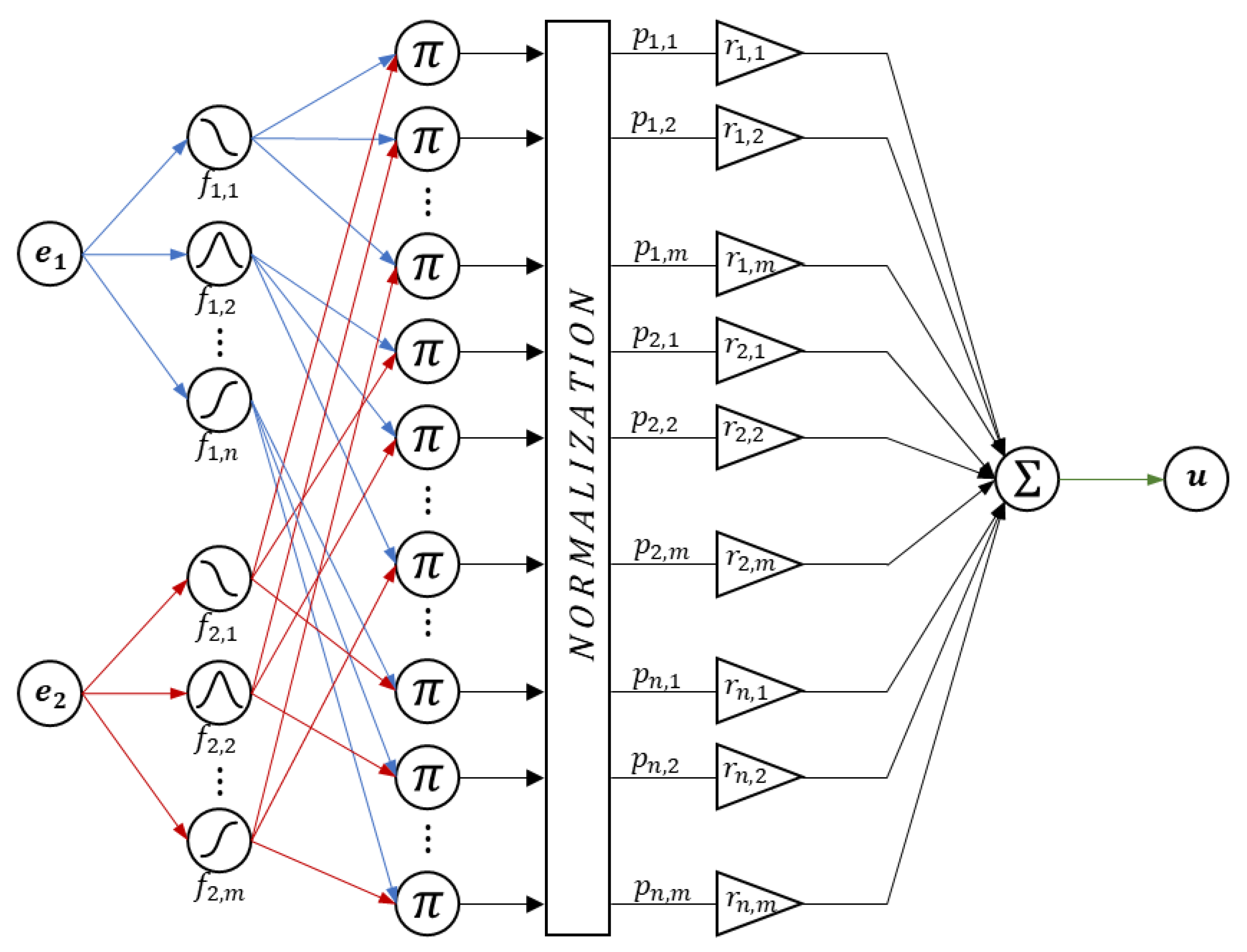
The internal structure of the neuro-fuzzy controller is illustrated in Figure 5; it follows the general framework introduced in [36], consisting of five processing layers: an input layer that receives the signals, a fuzzification layer where each input is mapped into membership degrees, a rule evaluation layer where fuzzy conditions are combined, a normalization layer that weights the activation strength of each rule, and finally an output layer where defuzzification using a weighted average yields a crisp output.
Unlike traditional Adaptive Neuro-Fuzzy Inference System (ANFIS) implementations, this study adopts a fixed-parameter neuro-fuzzy controller with zero-order Takagi–Sugeno consequents and no adaptive training. This choice prioritizes predictability during fast frequency events, simplifies verification and embedded implementation, and avoids sensitivity to measurement noise and dataset specific bias [37]. A fixed-parameter design is employed instead of adaptive training for the following reasons:
-
Inertial response and the initial stage of primary regulation unfold over short time windows (hundreds of milliseconds to a few seconds). Introducing online adaptation during these transients may yield time-varying closed loop dynamics and nonmonotonic actions, which can jeopardize frequency recovery [38]. A fixed parameter zero-order Takagi–Sugeno design guarantees deterministic behavior and repeatability [37].
-
Grid support controllers often face stringent requirements for verification, validation, and fail-safe operation according to IEEE 1547-2018 [9] and IEEE 1547.1-2020 [39]. In practice, product certification, such as UL-1741 Supplement SB [40], follows prescribed test procedures with specified parameter ranges and response times. Controllers with deterministic, bounded settings therefore align naturally with these test matrices and facilitate verification and repeatability, whereas online adaptation can complicate repeatable testing under fixed test conditions.
-
Online adaptation can be sensitive to measurement noise (frequency estimation, ROCOF, SOC observers). Prior reviews have noted that measurement noise and modeling uncertainties can undermine the robustness of online or adaptive SOC estimators, particularly for Kalman filter-based and observer-based approaches [41].
-
Recent reviews indicate that machine-learning models in power systems face risks of overfitting and limited generalization under nonstationary and heterogeneous data, which motivates scenario-based design with explicit rule structures rather than purely data-driven tuning [42].
In the proposed control strategy, the inputs are the required power (normalized by the inverter rating) and the state-of-charge deviation of the corresponding storage element. Gaussian membership functions are used in the central region and sigmoidal functions at the boundaries to ensure continuity and saturation. The rule bases define the participation factors of the supercapacitor and battery branches according to SOC and power demand, enabling a smooth transfer of the required power. Tuning scenarios span negative and positive frequency deviations and low, medium, and high required power levels, consistent with the cases reported in Section 4. The tuning criteria and the complete rule bases and membership function parameters are provided in the following subsections.

3.3.1. Supercapacitor Control System

The hybrid energy storage system is composed of supercapacitor groups and a battery bank. In this paper, it is proposed that during a generation–load power imbalance event, only one of the supercapacitor groups will supply active power, so that the other groups will remain in reserve for the following power imbalance events.
The selection of the supercapacitor group participating in frequency regulation is determined by its state-of-charge deviation ( Δ S O C S C , k ) and cumulative charge throughput ( Q k ), as indicated in Equation (23). As described in [43,44], the selected group is the one whose operating conditions minimize the cost function L k , which is designed to ensure active and balanced management of the supercapacitor bank.
L k = γ φ k + λ Q k Q ¯ Q ¯
The function φ k depends on the type of frequency deviation. For a positive deviation, the selection favors groups with lower state-of-charge deviation values, while for a negative deviation, it favors groups with higher values, as defined in Equation (24). In addition, the accumulated charge of each group is compared with the average throughput across all groups ( Q ¯ ). Consequently, groups with higher accumulated usage incur a greater cost and are less likely to be selected, whereas groups with lower accumulated usage are prioritized.
φ k = Δ S O C S C , k ,     Δ ω > 0 Δ S O C S C , k ,     Δ ω < 0
Group selection can be computed in advance while the HESS is in standby mode, anticipating a frequency regulation event. This allows the groups with the lowest cost to be pre-identified for both positive and negative frequency deviations, thereby alleviating computational overhead at the onset of a regulation event.
The parameters γ and λ are weighting factors assigned to each term of the cost function. Their values are manually adjusted according to the relative cumulative throughput of the groups. Thus, if certain supercapacitors exhibit faster degradation, the weight λ is increased relative to γ , ensuring that aging effects are properly accounted for in the selection process.
The design of the supercapacitor controller consists in the supercapacitors being used for inertial response and primary regulation, in the latter, fully or partially, depending on their state of charge and the required power. Equations (25) and (26) define the power to provide virtual inertial and primary regulation, respectively; the value of the required power must be within the operating range of the inverter, as indicated in Equation (27). Therefore, the reference power of the supercapacitors ( P S C , r e f ) is introduced into Equation (28), where α t is the participation factor of the supercapacitors, that is, the proportion of power provided by the supercapacitors during the inertial response and primary regulation, which has a value between 0 and 1.
P v i = K v i d Δ ω 1 d t ,   t < t n d r                   0                     ,   t t n d r
P p r = 1 R 1 Δ ω 1
P S C , d = P H , m á x ,                                         P v i + P p r < P H , m á x   P v i + P p r , P H , m á x P v i + P p r P H , m á x P H , m á x ,                                           P v i + P p r > P H , m á x
P S C , r e f = α t P S C , d
The participation factor is calculated by means of a neuro-fuzzy controller ( N F S C ) which has as inputs the required power and the state of charge of the supercapacitors. The power that enters as input to the neuro-fuzzy controller is expressed based on the maximum power of the inverter ( P H , m á x ), as shown in Figure 6.
The tuning criterion is to ensure a smooth transition of the required power from the supercapacitors to the batteries. In this scheme, the supercapacitors supply energy during the inertial response and the initial part of primary regulation, after which the batteries take over, thereby avoiding a sudden increase in battery power.
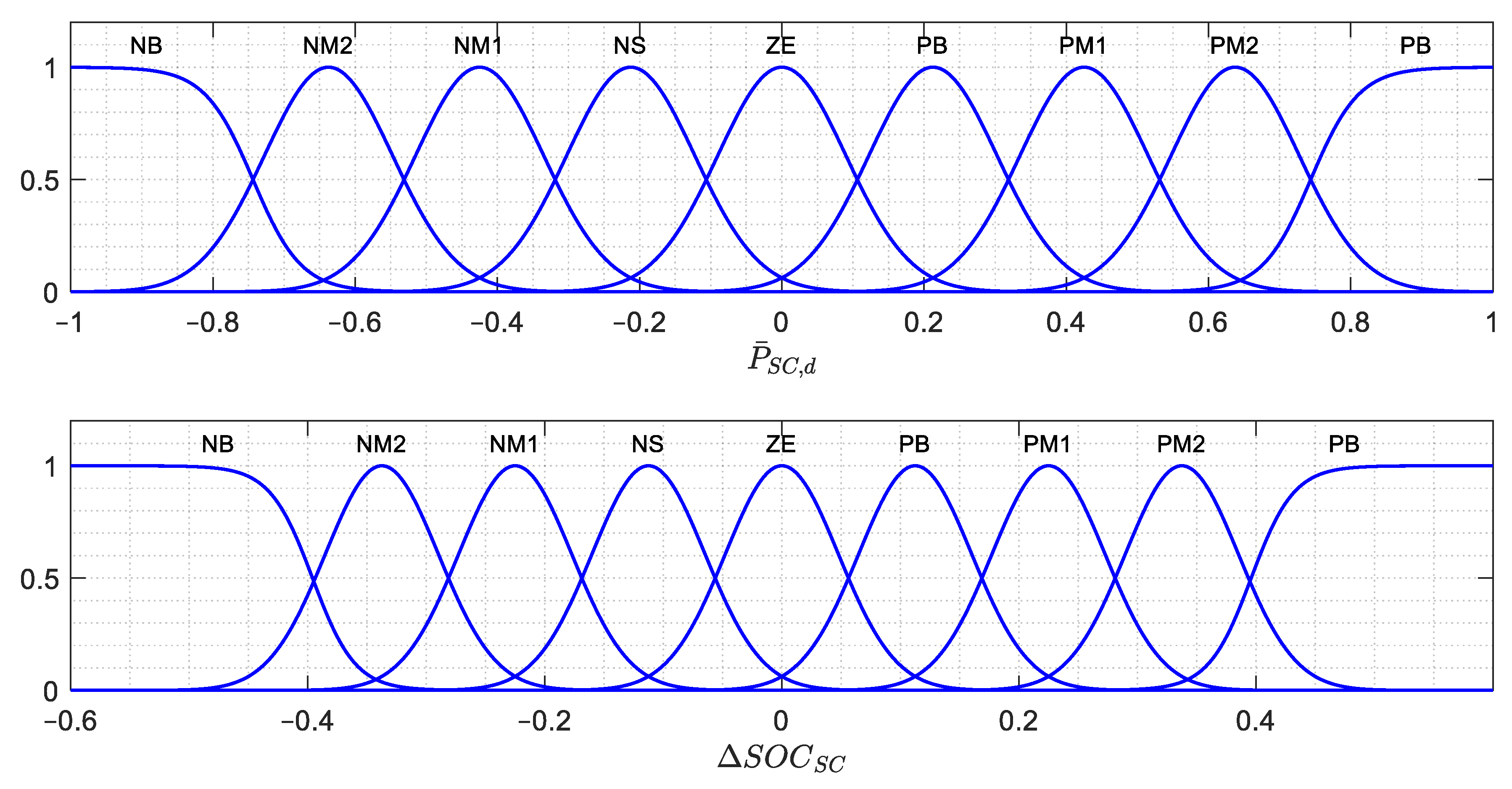
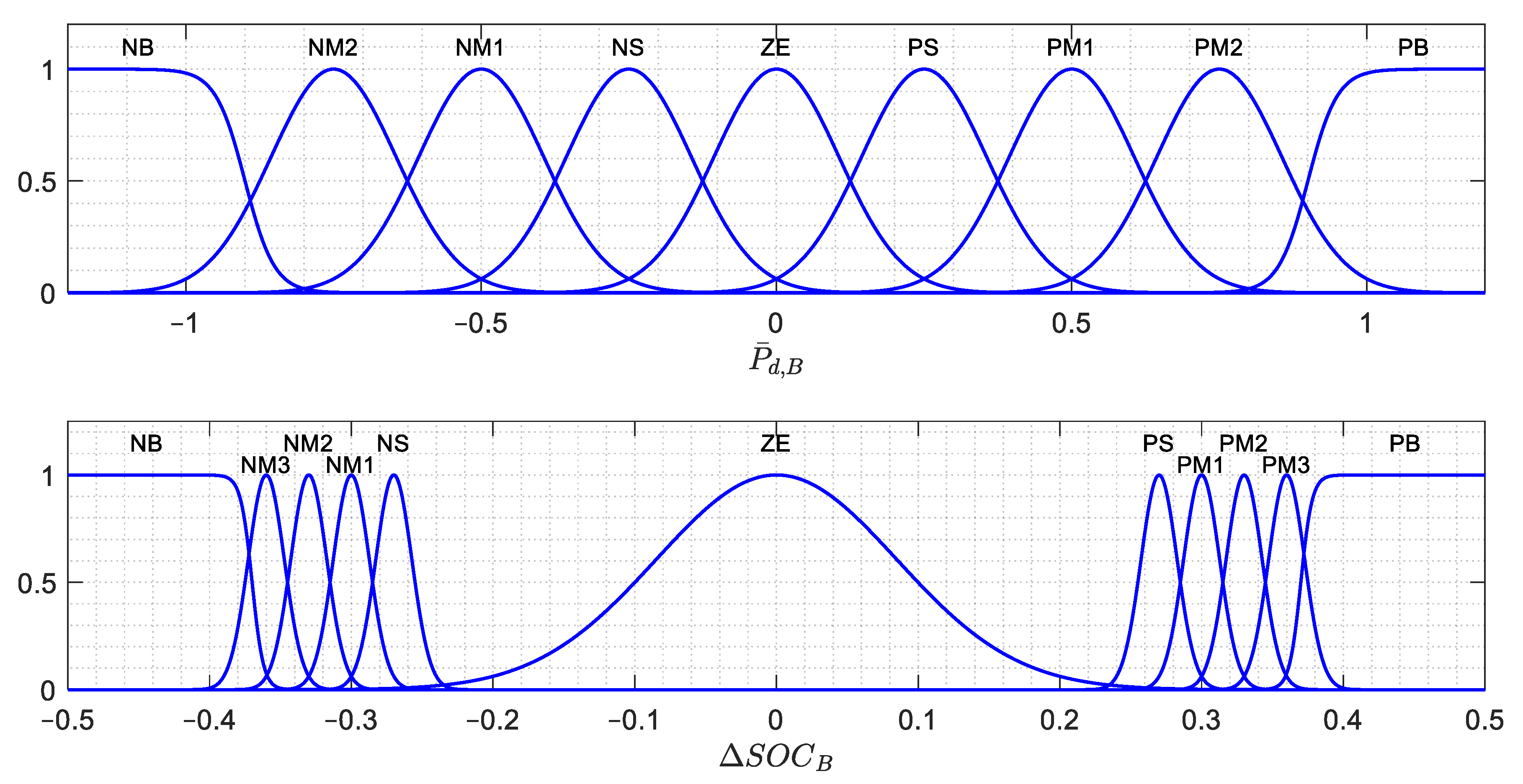
The parameters of the membership functions (see Figure 7) and the rule base were defined through multiple simulations under different levels of generation and load power imbalance and the percentage of renewable energy penetration (PRER), for negative frequency deviations and with the initial deviation of the supercapacitor state of charge equal to zero. For high required power, the transition between storage technologies proceeds gradually as the deviation of the supercapacitor state of charge decreases. For medium required power, the transition begins at a deviation of the supercapacitor state of charge of approximately −0.25, which increases the participation of the supercapacitors in primary regulation. For low required power, the transition begins only at a deviation close to −0.375. Thus, the supercapacitors contribute more than the batteries during the time window in which only primary regulation occurs. Symmetrical thresholds are used when the frequency deviation is positive.
The rule base is defined in Table 2. This table shows that each input variable has nine linguistic values, being “NB”, large negative; “NM2”, medium negative 2; “NM1”, medium negative 1; “NS”, small negative; “ZE”, zero; “PS”, small positive; “PM1”, medium positive 1; “PM2”, medium positive 2; and “PB”, large positive.

3.3.2. Battery Control System

Unlike supercapacitors, batteries have a high energy density, which is why they are used for longer periods. In this work, it is proposed that the batteries complement the operation of the supercapacitors during the inertial response and primary regulation when the charge level of the supercapacitors is low, as indicated in Equation (29).
Unlike the other methods described in Section 3.2, the proposed controller explicitly considers the required power as an additional input, see Figure 8. In the alternative methods, the absence of this input leads to a reduction in battery participation when entering the transition zone, even if the required power demand is minimal. As a result, these approaches do not allow the minimum power to be continuously supplied until the state of charge (SOC) reaches a prudent level at which battery participation can be safely reduced. In contrast, the proposed method enables more effective utilization of the batteries, preventing the SOC from entering the prohibited zone and thereby preserving battery health.
P B , d = 1 α t P S C , d
The required power that enters as input to the neuro-fuzzy controller is saturated according to inverter limits, as expressed in Equation (30). The reference power is defined in Equation (31), where β t is the participation factor of the batteries, that is, the proportion of power provided by the batteries during frequency regulation, which is a value between 0 and 1.
P B , d = P H , m á x P S C ,                                     P S C + P B , v i + r p < P H , m á x   P B , v i + r p ,     P H , m á x P S C + P B , v i + r p P H , m á x P H , m á x P S C ,                                     P S C + P B , v i + r p > P H , m á x
P B , r e f = β t P B , d
The participation factor β t is calculated by means of the neuro-fuzzy controller N F B , s , which has as inputs the normalized required power ( P ¯ B , d ) and the SOC deviation of the batteries ( Δ S O C B ).
The tuning criterion is used to achieve a smooth transition of the required power from the batteries to the conventional generating unit (CGU) when spinning reserve is available. It also aims to maximize battery capacity utilization when spinning reserve is not available by preventing the state of charge from falling below −0.4, since operating in this prohibited zone is detrimental to the battery [33,45].
The membership function parameters (see Figure 9) and the rule base were defined through multiple simulations under different levels of generation and load power imbalance and the percentage of renewable energy penetration (PRER) offsets, for cases with negative frequency deviation and zero initial deviation of the battery state of charge. For high required power, battery participation begins to decrease gradually once the deviation of the battery state of charge reaches approximately −0.25, thereby avoiding abrupt reductions in battery power that could cause unwanted transients in the frequency response. At medium required power, the transition is initiated at about −0.30, a value that approaches the prohibited zone. For low required power, the transition is triggered only near −0.35, and this threshold is chosen to avoid entering the prohibited zone. In this way, the remaining energy in the batteries is used to attenuate the frequency deviation. Symmetrical thresholds are used when the frequency deviation is positive.
The rule base is defined in Table 3. This table shows that the input variable P ¯ B , d has nine linguistic values, being “NB”, large negative; “NM2”, medium negative 2; “NM1”, medium negative 1; “NS”, small negative; “ZE”, zero; “PS”, small positive; “PM1”, medium positive 1; “PM2”, medium positive 2; and “PB”, large positive. The other input variable Δ S O C S C has eleven linguistic values, being: “NB”, large negative; “NM3”, medium negative 3; “NM2”, medium negative 2; “NM1”, medium negative 1; “NS”, small negative; “ZE”, zero; “PS”, small positive; “PM1”, medium positive 1; “PM2”, medium positive 2; “PM3”, medium positive 3; and “PB”, large positive.

3.3.3. Conventional Generation Unit

The signal that the controller sends to the conventional generation unit ( Δ P L p r , 1 ) is introduced in Equation (32). This quantity, here referred to as the compensated power, represented the reduction in the battery reference power when the state of charge enters the transition zone. To avoid creating a new generation–load power imbalance, this reduction must be assumed by the conventional plant.
Δ P L p r , 1 = 1 β t P B , r e f

3.4. Implementation Considerations for Real-World Deployment

The proposed controller acts as a supervisory layer that issues reference powers to the storage subsystems while respecting device limits and the timing of inner converter loops. Although the study is simulation-based, the structure and tuning were chosen to support practical deployment with predictable behavior, modest computational demand, and clear interfaces for sensing and actuation. The following items summarize practical considerations for implementing the proposed controller in real-world deployment and should guide its realization from simulation to field prototypes and commercial systems.
Sensing and estimation: Frequency, ROCOF, and SOC signals must be filtered to balance noise rejection and delay. Practical implementations should include input validation and simple plausibility checks to avoid nonmonotonic actions during fast transients [46,47].
Actuation bandwidth and device limits: Reference updates must respect inverter current and power limits, DC-bus constraints, and safe operating areas of batteries and supercapacitors. The controller enforces hard limits on total HESS power and applies rate limiting to prevent step-like commands that could excite inner current or voltage loops [48].
Real-time computation budget: The neuro-fuzzy supervisor uses a zero-order Takagi–Sugeno structure with fixed parameters. Per-cycle cost grows linearly with the number of rules; in the configuration used here (two inputs, Gaussian and sigmoidal membership functions, zero-order consequents), the supervisor performs on the order of 102 rule evaluations per cycle. At supervisory rates of 50–200 Hz, the computational load is modest for typical embedded targets such as digital signal processors (DSPs) or field-programmable gate arrays (FPGAs), with additional headroom on modern devices, while inner converter loops continue to operate at kHz rates. No online training is executed at run time, so the computational profile is fixed and deterministic [36,37].
Timing, delays, and communications: To reduce sensitivity to delay and jitter, the supervisory logic should execute locally at the HESS controller. If remote signals are required, include watchdogs, timestamps, and safe fallback modes, and limit the rate of change in setpoints to maintain stable closed-loop behavior [49].
SOC estimation and device protection: Participation factors are scheduled with SOC-dependent thresholds to ensure a smooth handover from supercapacitors to batteries and to avoid entry into prohibited SOC regions. Periodic recalibration of SOC estimators and logging of depth of discharge and temperature are recommended for condition-based maintenance [41].
Verification, validation, and compliance: Grid-support functions are verified against defined settings and response criteria as specified in IEEE 1547 [9] and IEEE 1547.1 [40]. Product certification commonly follows UL 1741 Supplement SB [40], which references test procedures aligned with IEEE 1547.1. A fixed-parameter design with bounded outputs simplifies controller-in-the-loop and hardware-in-the-loop testing and facilitates repeatable compliance assessment.
Integration with plant controls: Define interfaces for reference powers, status flags, fault handling, and curtailment requests from the plant controller. Ensure that supervisory decisions do not conflict with protections and that limits from the plant controller take precedence when required [9,39].
Decentralized deployment and scalability: Each HESS executes the fixed-parameter neuro-fuzzy supervisor locally using only local signals (frequency, required power, and SOC). There is no centralized optimization or online training. As a result, the approach scales by replication across sites and is largely independent of the total number of generators or the renewable penetration level in the wider system. Optional plant-level coordination exchanges setpoints and status flags but does not change the per-site computational cost.
A summary of thresholds, membership functions, and rule bases is provided in the preceding subsections. The scenario-based results in Section 4 illustrate the expected behavior under a range of operating conditions.

4. Results

This section presents the simulation results obtained using a hybrid energy storage system (HESS) for frequency regulation in a two-area power system. The first subsection presents the results for the inertial response and primary frequency regulation, while the second subsection shows the simulation results for battery state-of-charge control.
The data used in the simulations are provided in Table 4. The parameters related to conventional generation units correspond to typical values extracted from [30], the classical reference by Prabha Kundur, which has been widely employed in high-impact studies on frequency regulation. The supercapacitor and battery data were taken from [50,51], respectively, both published in high-impact journals. In this study, per-unit values are defined on a power base of 20 MW and an energy base of 20 MWh; the HESS is assumed to have an energy storage capacity of 0.04 p.u. for the battery and 0.0008 p.u. for each of the 12 supercapacitor groups, resulting in a combined energy storage capacity of 0.496 p.u., corresponding to realistic scales that have been deployed in functional projects using supercapacitors and batteries, such as Longyuan Power’s HESS project located in Zhaoyuan City, Shandong Province, China. Furthermore, the inverter rating was defined considering a 3% spinning reserve for primary frequency regulation, which is consistent with mandatory requirements in countries such as Peru [52], Colombia [53], and Spain [54].

4.1. Inertial Response and Primary Frequency Regulation

Nine scenarios are proposed to analyze the performance of the proposed control strategy in comparison with the other three strategies described in the previous chapter. These cases are detailed in Table 5, which shows that the variables that change are the load power variation ( Δ P L , 1 ) and the percentage of renewable energy penetration (PRER). In all scenarios, non-conventional generation is assumed to have replaced conventional generation in Area 1, resulting in a direct reduction in the inertia constant in that area. Additionally, non-conventional generation is not considered in Area 2. These simulation scenarios are used to evaluate both the inertial response and primary frequency regulation.
As shown in Table 6, the performance indicators ITSE, ISE, ITAE, and IAE, together with the frequency nadir, are reported for all scenarios, and the proposed method achieves the best values, especially in the most challenging cases with higher generation and load imbalance and higher renewable penetration. These indicators, along with the frequency nadir and ROCOF, have been widely used in prior studies [55,56,57] to demonstrate the benefits of control strategies under diverse system conditions, and in our study, they evidence robustness by confirming superior performance across scenarios with varying power imbalance and PRER.
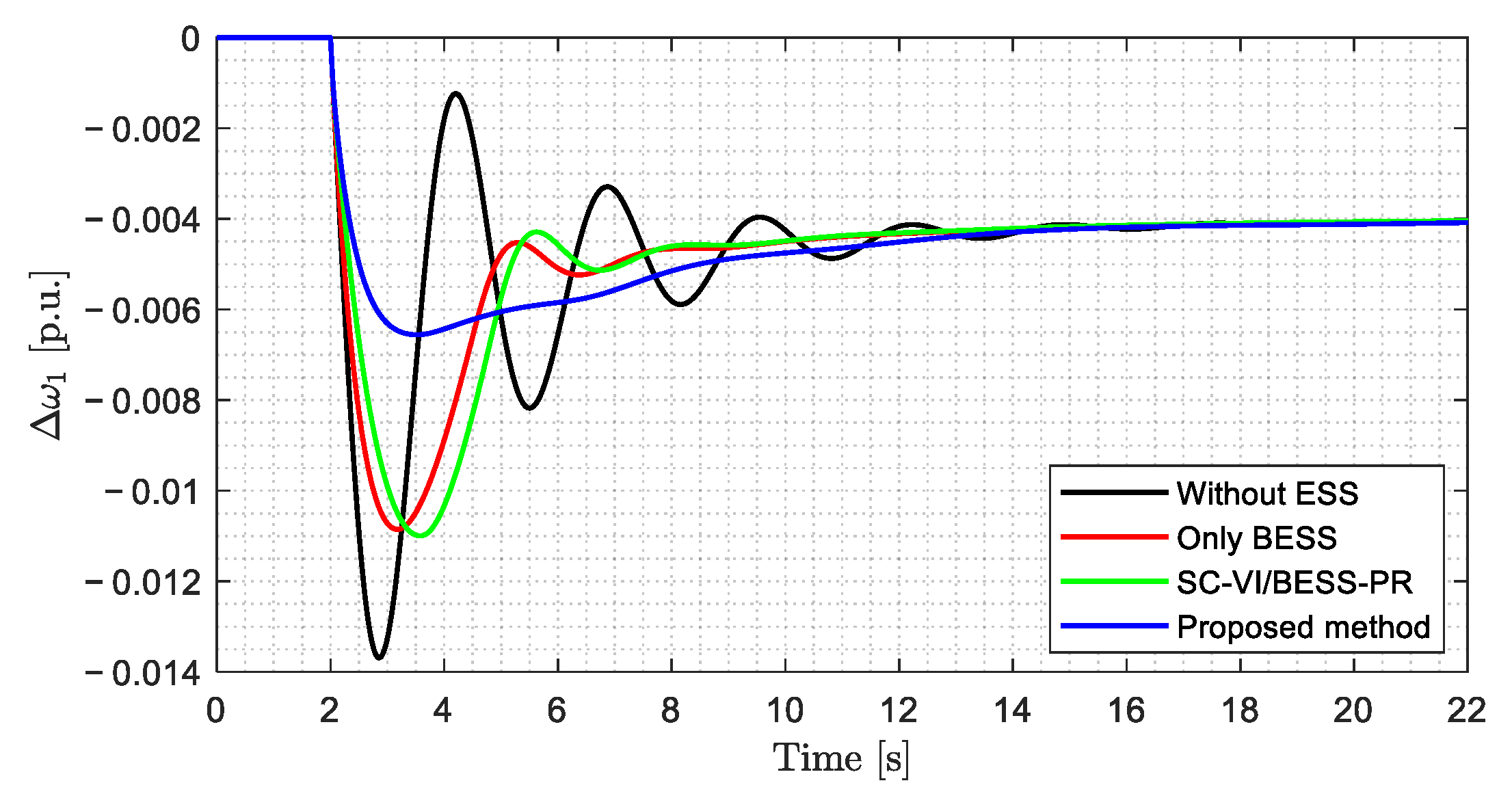
The time-domain results for Scenario 9 are shown in the following figures. In this scenario, Δ P L , 1 = 0.15   p . u . and P R E R = 40 % .  Figure 10 displays the time-domain frequency response of Area 1, where it can be seen and corroborated by the performance indicators in Table 6 that the proposed method significantly outperforms the others. It achieves a better nadir and rate of change of frequency (ROCOF), with a faster frequency recovery, as shown in Figure 11.
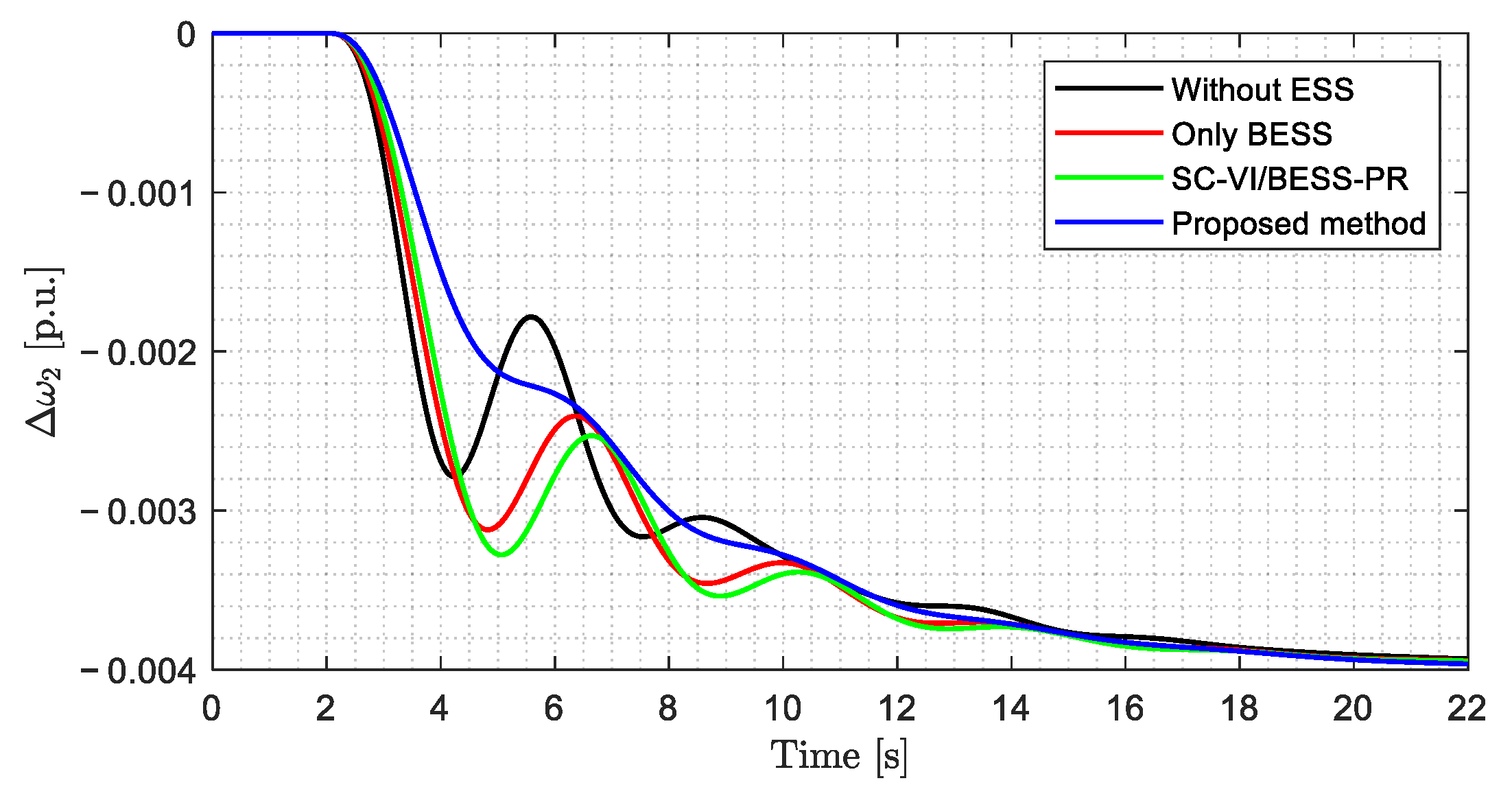
The time-domain frequency response without the energy storage system (ESS) exhibits the worst performance, clearly highlighting the need for virtual inertia provided by an ESS to counteract the reduced system inertia resulting from increased non-conventional generation. The time-domain frequency response of Area 2 using the proposed method exhibits fewer oscillations compared to the other strategies, as shown in Figure 12.
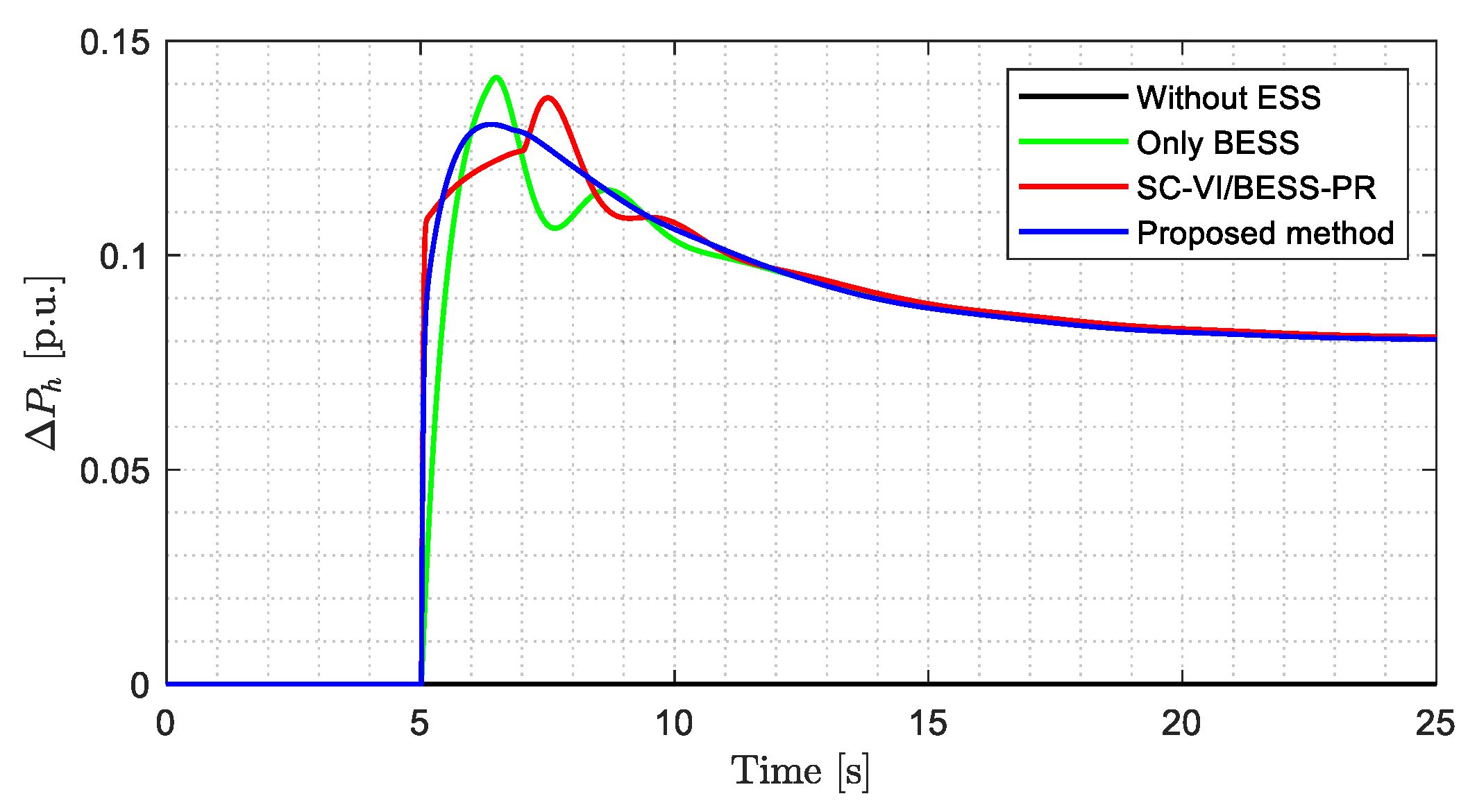
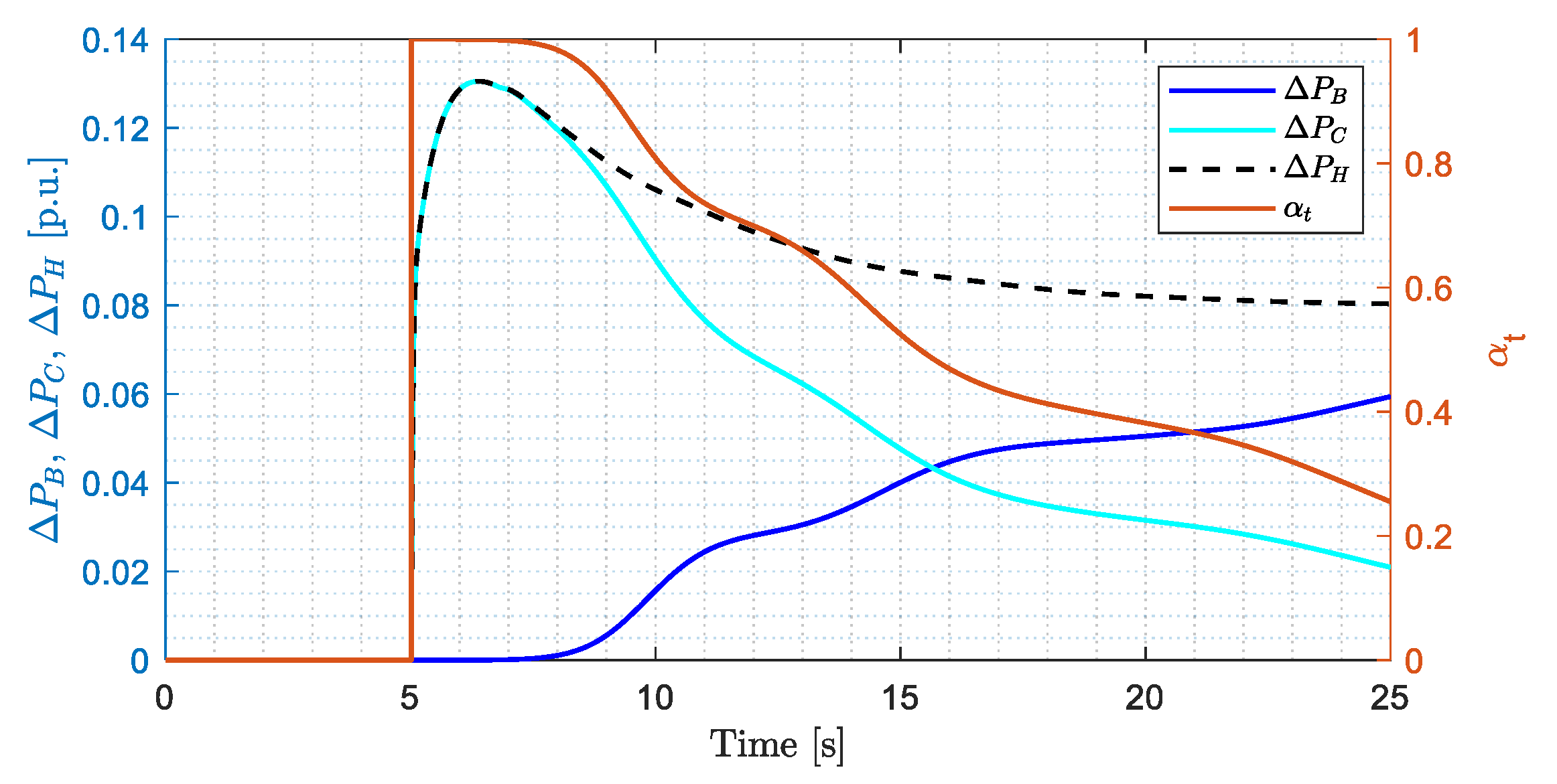
Figure 13 shows that the inverter power response under the proposed method reaches the lowest peak value compared to the other methods, indicating a greater capacity margin to support larger generation–load imbalances. Additionally, it is observed that the participation factor α t decreases to approximately 0.265, see Figure 14, suggesting that 73.5% of the power initially supplied by the supercapacitors is instead delivered by the batteries at the end of the regulation period. This redistribution reduces the impact on the frequency time response in Area 1, ensures a smooth transition between supercapacitors and batteries, and prevents sudden increases in the high rates of change in battery power (see Figure 15).
The time-domain frequency response of Area 1 during primary and secondary regulation is shown in Figure 16. It is assumed that secondary frequency regulation lasts for 5 min, and that the conventional generation unit (CGU) has sufficient spinning reserve to restore the frequency. As observed in this figure, all control strategies exhibit similar performance during the secondary regulation period.
Additional results include the energy supplied by the ESSs and the CGU to the power system in order to mitigate the generation–load imbalance. These results are shown in Table 7. As observed, the energy provided by the CGU without ESS is approximately the same as that of the other alternatives; however, the impact of the disturbance is greater in the frequency time response of Area 1.
As shown in Table 7, under the proposed method, the energy delivered by the supercapacitor is greater than that delivered by the battery in all scenarios during primary frequency regulation. Even in scenarios with low generation–load power imbalance, the supercapacitor supplies all the energy. However, when both primary and secondary regulation are considered, the energy delivered by the battery exceeds that delivered by the supercapacitor. The battery-to-supercapacitor energy ratio is approximately 1.3:1 in low-imbalance scenarios and increases to 5.38:1 in high-imbalance scenarios.
This implies that, under average conditions, the supercapacitor could replace a significant portion of the battery’s energy storage capacity and contribute to improved system performance. Moreover, since supercapacitors are less expensive than batteries and offer a significantly higher number of life cycles [58], the installation cost of the ESS can be reduced, and a HESS may achieve a longer lifetime compared to a BESS.
The “SC-VI/BESS-PR” method also employs a HESS; however, unlike the proposed method, it uses the supercapacitor exclusively for inertial response and the battery for primary regulation. As shown in Table 7, this strategy does not contribute to reducing the battery’s energy storage requirements. In all scenarios, the amount of energy delivered by the battery is nearly the same when comparing the “Only BESS” and “SC-VI/BESS-PR” strategies.
Furthermore, when comparing the “Only BESS” and “SC-VI/BESS-PR” strategies, the energy delivered by the supercapacitor is not significant relative to the energy delivered by the batteries. Considering the similarities in the time-domain frequency response and performance indicators in Area 1, the contribution of the supercapacitor in providing virtual inertia is mainly noticeable in the ROCOF improvement, as shown in Figure 11.
To evaluate the impact of the proposed method on battery lifespan, degradation metrics were computed from the onset of the generation–load imbalance until full frequency restoration (see Table 8). These indicators cover both primary and secondary regulation stages and include the following: average C-rate ( C a v g ), RMS C-rate ( C r m s ), peak C-rate ( C p e a k ), depth of discharge ( D o D ), equivalent full cycles ( E F C ), peak rate of change in battery power, and the Miner’s damage fraction ( D M ). Such metrics are widely adopted in the scientific literature to assess battery degradation [59,60,61].
The results indicate that the proposed method achieves the most favorable values across all metrics, with a notable reduction in the Miner’s damage fraction, thereby mitigating battery degradation. This effect is further illustrated in Figure 14, which depict the rate of change in battery power in Scenario 9.
To analyze the controller’s sensitivity to variations in load power and PRER, normalized sensitivity calculations were performed for Scenario 5, as the selected load and PRER values lie in the middle of the studied ranges. The results are summarized in the following tables.
The load power results presented in Table 9 show that when the load decreases, no significant differences are observed. However, when the load increases, the proposed method exhibits lower sensitivity than the other controllers in terms of the ITSE and ITAE performance indicators.
Regarding PRER sensitivity, the proposed method was found to be slightly less sensitive in the integral performance indicators, but it showed a notably lower sensitivity in the frequency nadir compared to the other strategies, see Table 10.
It should be noted that in the “Only BESS” strategy, supercapacitors are not included, and in the “SC-VI/BESS-PR” strategy, supercapacitors are employed only for the inertial response. Consequently, these strategies are not affected by changes in the capacities of the supercapacitors and batteries, and therefore a sensitivity analysis is not applicable for a direct comparison with the proposed method. Similarly, in the battery controller, variations in battery capacity would only affect runtime rather than sensitivity, and thus would not provide a meaningful comparison with other control strategies.

4.2. SOC Control

In this section, four scenarios are simulated to compare three battery state-of-charge (SOC) control strategies. These scenarios are detailed in Table 11 and show that the variables that differ are the load power variation Δ P L , 1 , the initial SOC condition ( Δ S O C 0 ), and whether spinning reserve is considered in addition to the HESS.
Scenarios 10 and 11 consider the same Δ P L , 1 value of 0.10 and an initial Δ S O C 0 of −0.275; however, only Scenario 10 includes additional spinning reserve for primary regulation. These two scenarios are designed to compare the control strategies when the power requirement is low and the SOC is at the beginning of the transition zone.
Similarly, Scenarios 12 and 13 have the same Δ P L , 1 value of 0.15 and Δ S O C 0 of −0.325, but only in Scenario 12 is additional spinning reserve considered for primary regulation. These scenarios are intended to compare the strategies under higher power demand, with the SOC positioned in the middle of the transition zone.
Table 12 shows the results of performance indicators (IAE, ISE, ITAE, and ITSE) and also presents the values at the end of the simulation of the state of charge of the batteries and the time at which the decrease in the delivered power starts to avoid operating in the forbidden zone and damaging the lifetime of the batteries.
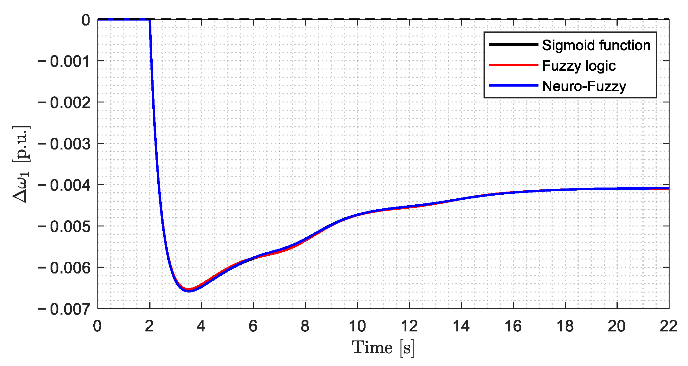
The time-domain frequency response in Scenarios 10 and 11 is shown in Figure 17 and Figure 18, respectively. As observed in these figures and the corresponding performance indicators, the results are similar across the three strategies, and the battery’s SOC also reaches the same value in all methods.
The most notable difference among the control strategies is found in the power response of the CGU, see Figure 19, when additional spinning reserve is considered for primary regulation. In this case, the power required by the proposed method is significantly lower, practically zero, compared to the other methods.
On the other hand, in Scenarios 12 and 13, the power required from the batteries is greater than in the previous scenarios, and SOC of the batteries is located in the middle of the transition zone. The results of Scenario 12 show a more pronounced difference in the power delivered by the CGU when additional spinning reserve is available for primary regulation (see Figure 20), with the proposed method being the least demanding on the CGU while achieving comparable performance indicator values (see Table 12 and Figure 21).
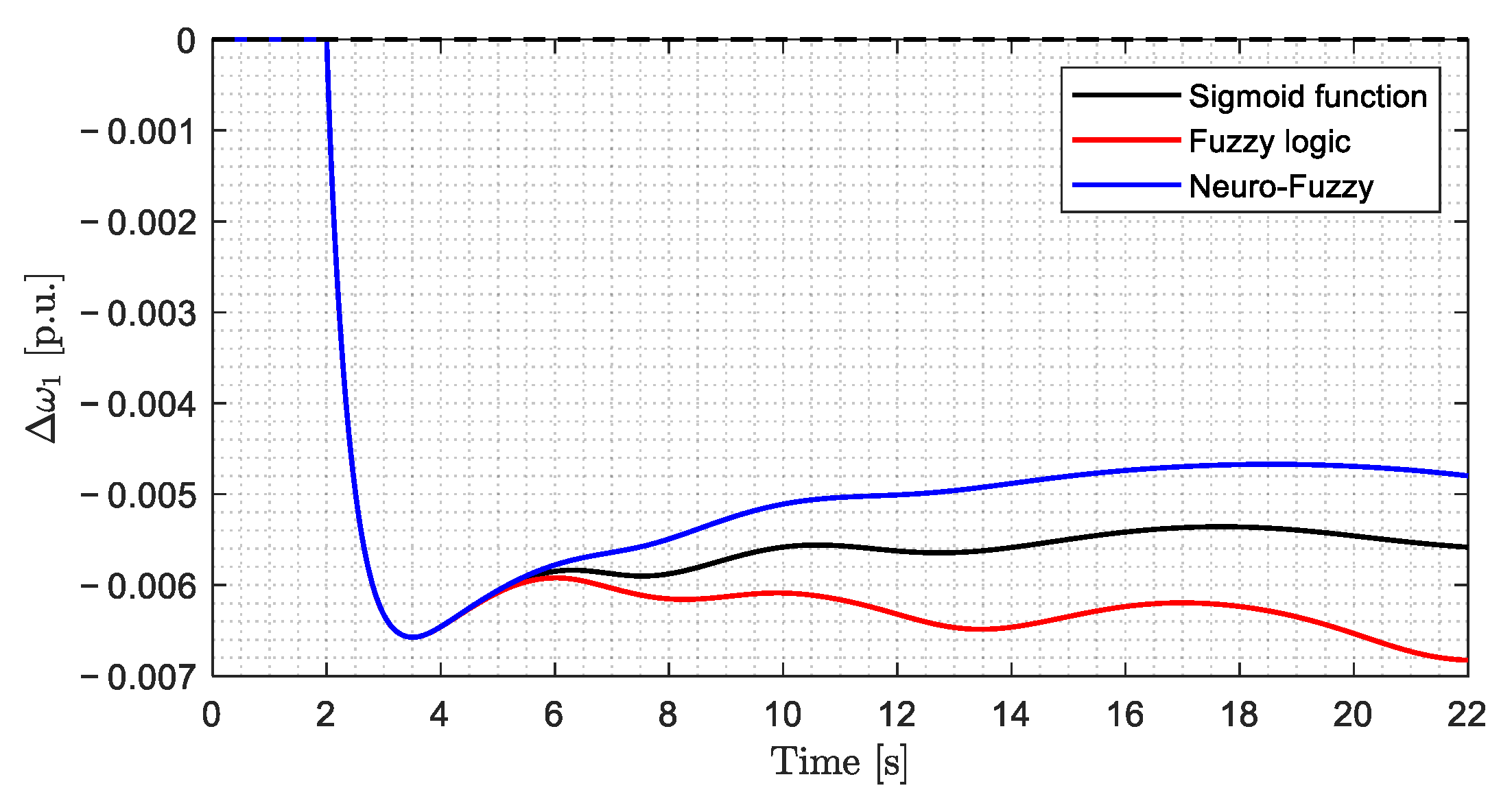
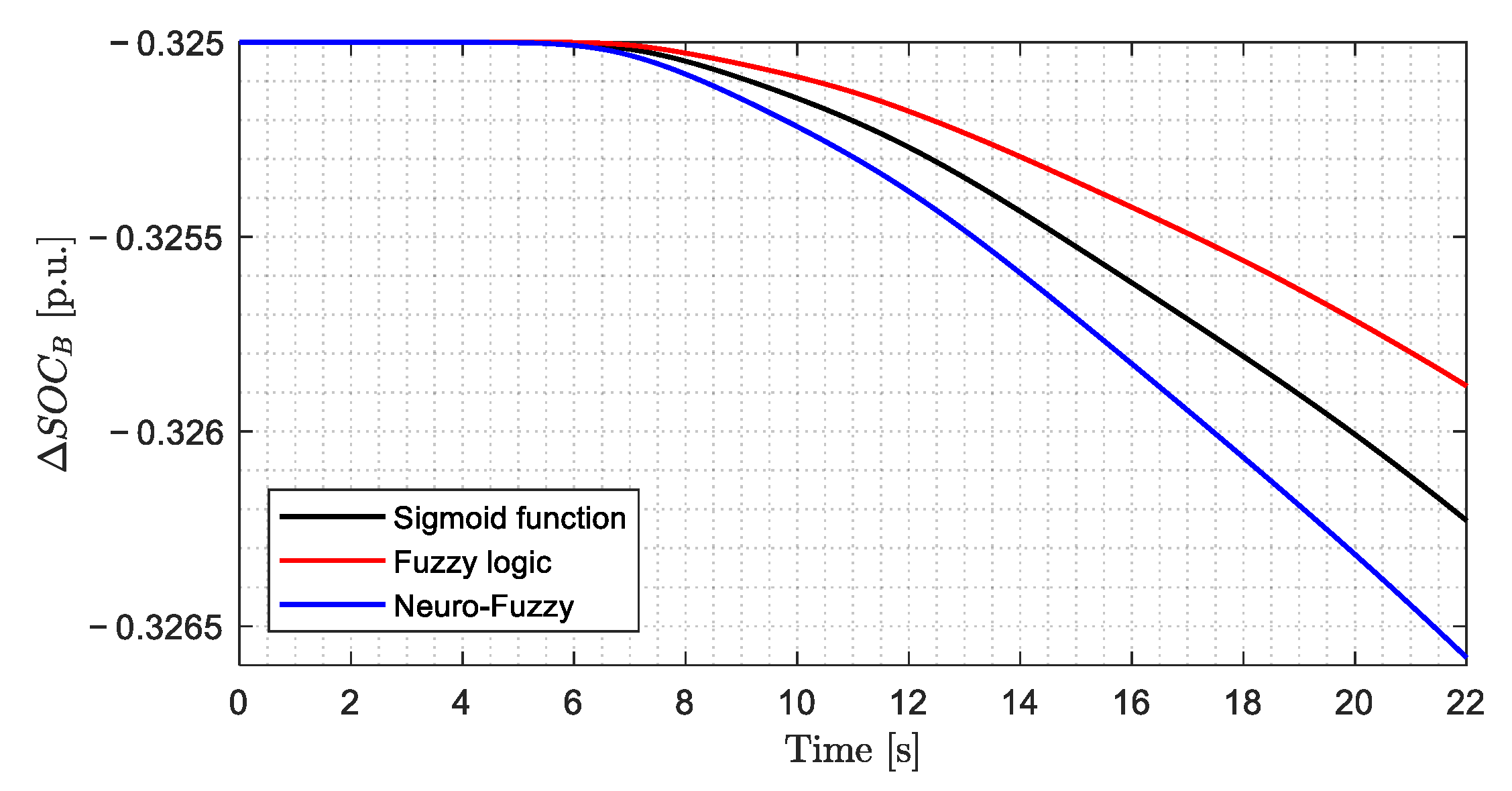
In Scenario 13, when no additional reserve is considered, the time-domain frequency response of Area 1 shows a noticeably better performance under the proposed method (see Figure 22). This method achieves the best performance indicators, but also requires the highest amount of battery energy. Consequently, it results in the lowest SOC value, a behavior clearly depicted in Figure 23. However, in neither case does the SOC enter the prohibited zone.
Based on the information presented regarding conventional generation plants in some countries, it would not be necessary to maintain a spinning reserve in plants equipped with a HESS, since the stored energy effectively fulfills that role. Consequently, the 3% originally allocated as spinning reserve can instead be traded in the daily scheduling market. As a simple illustrative exercise, considering the parameters outlined in Section 4.1 and assuming an energy price of 130 USD/MWh, the sale of 3 MW continuously over one year would yield approximately 1.14 MUSD.
According to [62], the average investment costs are 132 USD/kWh for batteries and 2628 USD/kWh for supercapacitors. Table 13 summarizes the storage technology costs (in kUSD) for each of the proposed alternatives, where it can be observed that the proposed HESS configuration exhibits the highest capital requirement among the hybrid options. It should also be noted that the cost of the conversion system is higher in HESS implementations, as they require an additional DC–DC converter for the supercapacitor branch.
Nevertheless, the performance results obtained in this study, including frequency regulation metrics and degradation indicators, demonstrate that despite the higher investment, the proposed method provides superior benefits in terms of frequency stability under high renewable penetration and in extending battery lifetime.

5. Conclusions

This work presented a coordinated control strategy based on neuro-fuzzy networks applied to a hybrid energy storage system composed of batteries and supercapacitors. The proposed controller was designed to emulate virtual inertia and provide primary frequency regulation, leveraging the high-power density and fast dynamic response of supercapacitors to support the initial phase of frequency regulation. By dynamically adjusting the participation factor, and thus the power references of the supercapacitors and batteries, according to the real-time state of charge of supercapacitors and the level of power demand, the control system enabled a smooth transition of regulatory responsibility from supercapacitors to batteries. This approach prevents the rapid onset of high discharge rates in the battery subsystem, enabling a more gradual and controlled activation of the batteries. Consequently, the system achieved a better primary frequency regulation performance, reflected in improved dynamic metrics such as the frequency nadir, ISE, and ITAE.
In addition, the proposed controller for state-of-charge management in the battery subsystem was tested under scenarios with different initial conditions and levels of spinning reserve. Notably, in the absence of spinning reserve, the controller showed significant improvements in performance. The performance indices IAE, ITAE, ISE, and ITSE all demonstrated that the proposed method outperformed conventional control approaches, achieving better primary regulation while preserving the integrity of the energy storage system.
Finally, the coordinated interaction with the conventional generation unit, when spinning reserve is considered, ensured reliable frequency support during transitions, avoiding disturbances when storage limits were reached. In conclusion, the proposed strategy effectively addresses frequency regulation challenges in low-inertia systems.
As future work, we intend to integrate the control strategy into a model of a real power grid and evaluate it under realistic conditions using historical renewable profiles, sensor noise, bounded communication delays, and diverse operating scenarios, with an emphasis on overall performance, scalability on larger multi-area systems, and the impact of smoother power transfers on battery lifespan in long-term simulations. In parallel, we plan to develop a HESS sizing methodology that accounts for grid conditions, PRER, inverter ratings, and SOC constraints, and we expect to design a supercapacitor-group selection and rotation policy to minimize differential aging and promote homogeneous wear. Finally, we aim to conduct controller-in-the-loop and hardware-in-the-loop validation to assess real-time execution, latency margins, and numerical stability, including runtime profiling of the fixed-parameter neuro-fuzzy supervisor on embedded DSP/FPGA targets to report per-cycle computational cost and achievable supervisory rates.

Author Contributions

Conceptualization, C.H.I.E. and M.T.P.; methodology, C.H.I.E.; software, C.H.I.E.; validation, C.H.I.E. and M.T.P.; formal analysis, C.H.I.E.; investigation, C.H.I.E.; resources, C.H.I.E.; data curation, C.H.I.E.; writing—original draft preparation, C.H.I.E.; writing—review and editing, C.H.I.E.; visualization, C.H.I.E.; supervision, M.T.P.; project administration, C.H.I.E.; funding acquisition, C.H.I.E. All authors have read and agreed to the published version of the manuscript.

Funding

This research received no external funding.

Data Availability Statement

The data supporting the findings of this study are contained within the article. Any additional inquiries can be addressed to the corresponding author.

Conflicts of Interest

The authors declare no conflicts of interest.

Abbreviations

The following abbreviations are used in this manuscript:
ANFISAdaptive Neuro-Fuzzy Inference System
BESSBattery Energy Storage System
CGUConventional Generation Unit
ESSEnergy Storage System
HESSHybrid Energy Storage System
IAEIntegral of Absolute Error
ISEIntegral of Squared Error
ITAEIntegral of Time-Weighted Absolute Error
ITSEIntegral of Time-Weighted Squared Error
PIDProportional–Integral–Derivative
PRERPercentage of Renewable Energy Replacement
ROCOFRate of Change of Frequency
SCSupercapacitor
SOCState of Charge

Appendix A

This section details the matrices A, B, and E of the state equation defined in Equation (13).
A = D 1 2 H 1 0 0 1 2 H 1 0 0 1 2 H 1 0 0 1 2 H 1 1 2 H 1 0 0 0 D 2 2 H 2 0 0 0 1 2 H 2 1 2 H 2 0 0 0 0 0 0 1 R 1 τ g , 1 0 1 τ g , 1 0 0 0 0 1 τ g , 1 0 0 0 0 0 0 0 1 τ t , 1 1 τ t , 1 0 0 0 0 0 0 0 0 0 0 1 R 2 τ g , 2 0 0 1 τ g , 2 0 0 0 1 τ g , 2 0 0 0 0 0 0 0 0 1 τ t , 2 1 τ t , 2 0 0 0 0 0 0 0 P s P s 0 0 0 0 0 0 0 0 0 0 0 k i , 1 B 1 0 0 0 0 0 k i , 1 0 0 0 0 0 0 0 k i , 2 B 2 0 0 0 0 k i , 2 0 0 0 0 0 0 0 0 0 0 0 0 0 0 0 1 τ b 0 0 0 0 0 0 0 0 0 0 0 0 0 1 τ s c 0 0 0 0 0 0 0 0 0 0 0 K e , B 0 0 0 0 0 0 0 0 0 0 0 0 0 K e , S C 0 0
B = 0 0 0 0 0 0 0 0 0 1 τ b 0 0 0 0 0 0 0 0 0 0 0 0 0 1 τ s c 0 0 T
E = 1 2 H 1 0 0 0 0 0 0 0 0 0 0 0 0 0 1 2 H 2 0 0 0 0 0 0 0 0 0 0 0 1 2 H 1 0 0 0 0 0 0 0 0 0 0 0 0 0 1 2 H 2 0 0 0 0 0 0 0 0 0 0 0 T

References

  1. Zhao, T.; Parisio, A.; Milanovic, J.V. Distributed Control of Battery Energy Storage Systems for Improved Frequency Regulation. IEEE Trans. Power Syst. 2020, 35, 3729–3738. [Google Scholar] [CrossRef]
  2. Shim, J.W.; Verbic, G.; Zhang, N.; Hur, K. Harmonious Integration of Faster-Acting Energy Storage Systems into Frequency Control Reserves in Power Grid with High Renewable Generation. IEEE Trans. Power Syst. 2018, 33, 6193–6205. [Google Scholar] [CrossRef]
  3. Cheng, Y.; Azizipanah-Abarghooee, R.; Azizi, S.; Ding, L.; Terzija, V. Smart Frequency Control in Low Inertia Energy Systems Based on Frequency Response Techniques: A Review. Appl. Energy 2020, 279, 115798. [Google Scholar] [CrossRef]
  4. Ulbig, A.; Borsche, T.S.; Andersson, G. Impact of Low Rotational Inertia on Power System Stability and Operation. IFAC Proc. Vol. 2014, 47, 7290–7297. [Google Scholar] [CrossRef]
  5. Kebede, A.A.; Kalogiannis, T.; Van Mierlo, J.; Berecibar, M. A Comprehensive Review of Stationary Energy Storage Devices for Large Scale Renewable Energy Sources Grid Integration. Renew. Sustain. Energy Rev. 2022, 159, 112213. [Google Scholar] [CrossRef]
  6. Xing, W.; Wang, H.; Lu, L.; Han, X.; Sun, K.; Ouyang, M. An Adaptive Virtual Inertia Control Strategy for Distributed Battery Energy Storage System in Microgrids. Energy 2021, 233, 121155. [Google Scholar] [CrossRef]
  7. Jufri, F.H.; Jung, J.; Sudiarto, B.; Garniwa, I. Development of Virtual Inertia Control with State-of-Charge Recovery Strategy Using Coordinated Secondary Frequency Control for Optimized Battery Capacity in Isolated Low Inertia Grid. Energies 2023, 16, 5463. [Google Scholar] [CrossRef]
  8. Varhegyi, G.; Nour, M. Advancing Fast Frequency Response Ancillary Services in Renewable-Heavy Grids: A Global Review of Energy Storage-Based Solutions and Market Dynamics. Energies 2024, 17, 3737. [Google Scholar] [CrossRef]
  9. IEEE Std 1547-2018; IEEE Standard for Interconnection and Interoperability of Distributed Energy Resources with Associated Electric Power Systems Interfaces. IEEE: New York, NY, USA, 2018.
  10. European Commission. Commission Regulation (EU) 2016/631 of 14 April 2016 Establishing a Network Code on Requirements for Grid Connection of Generators; Official Journal of the European Union: Brussels, Belgium, 2016. [Google Scholar]
  11. North American Electric Reliability Corporation. BAL-003-2—Frequency Response and Frequency Bias Setting; North American Electric Reliability Corporation: Atlanta, GA, USA, 2020. [Google Scholar]
  12. Chatzigeorgiou, N.G.; Theocharides, S.; Makrides, G.; Georghiou, G.E. A Review on Battery Energy Storage Systems: Applications, Developments, and Research Trends of Hybrid Installations in the End-User Sector. J. Energy Storage 2024, 86, 111192. [Google Scholar] [CrossRef]
  13. Margaris, I.D.; Papathanassiou, S.A.; Hatziargyriou, N.D.; Hansen, A.D.; Sorensen, P. Frequency Control in Autonomous Power Systems with High Wind Power Penetration. IEEE Trans. Sustain. Energy 2012, 3, 189–199. [Google Scholar] [CrossRef]
  14. Wu, Z.; Gao, W.; Gao, T.; Yan, W.; Zhang, H.; Yan, S.; Wang, X. State-of-the-Art Review on Frequency Response of Wind Power Plants in Power Systems. J. Mod. Power Syst. Clean. Energy 2018, 6, 1–16. [Google Scholar] [CrossRef]
  15. Tan, Y.; Muttaqi, K.M.; Ciufo, P.; Meegahapola, L.; Guo, X.; Chen, B.; Chen, H. Enhanced Frequency Regulation Using Multilevel Energy Storage in Remote Area Power Supply Systems. IEEE Trans. Power Syst. 2019, 34, 163–170. [Google Scholar] [CrossRef]
  16. Qian, Y.; Wang, H.; Zhou, M.; Lv, H.; Liu, Y. Frequency Trajectory Planning-Based Frequency Regulation Strategy for Wind Turbines Equipped with Energy Storage System. Chin. J. Electr. Eng. 2022, 8, 52–61. [Google Scholar] [CrossRef]
  17. Dhundhara, S.; Verma, Y.P. Grid Frequency Enhancement Using Coordinated Action of Wind Unit with Redox Flow Battery in a Deregulated Electricity Market. Int. Trans. Electr. Energy Syst. 2020, 30, 12189. [Google Scholar] [CrossRef]
  18. Rakhshani, E.; Remon, D.; Mir Cantarellas, A.; Rodriguez, P. Analysis of Derivative Control Based Virtual Inertia in Multi-Area High-Voltage Direct Current Interconnected Power Systems. IET Gener. Transm. Distrib. 2016, 10, 1458–1469. [Google Scholar] [CrossRef]
  19. Kerdphol, T.; Rahman, F.S.; Mitani, Y. Virtual Inertia Control Application to Enhance Frequency Stability of Interconnected Power Systems with High Renewable Energy Penetration. Energies 2018, 11, 981. [Google Scholar] [CrossRef]
  20. Turk, A.; Sandelic, M.; Noto, G.; Pillai, J.R.; Chaudhary, S.K. Primary Frequency Regulation Supported by Battery Storage Systems in Power System Dominated by Renewable Energy Sources. J. Eng. 2019, 2019, 4986–4990. [Google Scholar] [CrossRef]
  21. Fang, J.; Tang, Y.; Li, H.; Li, X. A Battery/Ultracapacitor Hybrid Energy Storage System for Implementing the Power Management of Virtual Synchronous Generators. IEEE Trans. Power Electron. 2018, 33, 2820–2824. [Google Scholar] [CrossRef]
  22. Akram, U.; Shah, R.; Mithulananthan, N. Hybrid Energy Stoarage System for Frequency Regulation in Microgrids with Source and Load Uncertainties. IET Gener. Transm. Distrib. 2019, 13, 5048–5057. [Google Scholar] [CrossRef]
  23. Nguyen-Huu, T.A.; Van Nguyen, T.; Hur, K.; Shim, J.W. Coordinated Control of a Hybrid Energy Storage System for Improving the Capability of Frequency Regulation and State-of-Charge Management. Energies 2020, 13, 6304. [Google Scholar] [CrossRef]
  24. Choi, W.Y.; Kook, K.S.; Yu, G.R. Control Strategy of BESS for Providing Both Virtual Inertia and Primary Frequency Response in the Korean Power System. Energies 2019, 12, 4060. [Google Scholar] [CrossRef]
  25. Amin, M.R.; Negnevitsky, M.; Franklin, E.; Alam, K.S.; Naderi, S.B. Application of Battery Energy Storage Systems for Primary Frequency Control in Power Systems with High Renewable Energy Penetration. Energies 2021, 14, 1379. [Google Scholar] [CrossRef]
  26. Wei, N.; Yan, X.; Han, X.; Ma, X.; Cui, J.; Sun, W. Research on Control Strategy of Hybrid Energy Storage System Participating in Primary Frequency Regulation of Power Grid. J. Phys. Conf. Ser. 2023, 2592, 012061. [Google Scholar] [CrossRef]
  27. Tan, J.; Zhang, Y. Coordinated Control Strategy of a Battery Energy Storage System to Support a Wind Power Plant Providing Multi-Timescale Frequency Ancillary Services. IEEE Trans. Sustain. Energy 2017, 8, 1140–1153. [Google Scholar] [CrossRef]
  28. Chen, W.; Sun, N.; Ma, Z.; Liu, W.; Dong, H. A Two-Layer Optimization Strategy for Battery Energy Storage Systems to Achieve Primary Frequency Regulation of Power Grid. Energies 2023, 16, 2811. [Google Scholar] [CrossRef]
  29. Fang, Z.; Shek, J.K.H.; Sun, W. A Review of Grid-Connected Hybrid Energy Storage Systems: Sizing Configurations, Control Strategies, and Future Directions. J. Energy Storage 2025, 118, 116226. [Google Scholar] [CrossRef]
  30. Kundur, P.S.; Malik, O.P. Power System Stability and Control, 2nd ed.; McGraw-Hill Education: New York, NY, USA, 2022; ISBN 9781260473544. [Google Scholar]
  31. Akram, U.; Khalid, M.; Shafiq, S. An Innovative Hybrid Wind-Solar and Battery-Supercapacitor Microgrid System—Development and Optimization. IEEE Access 2017, 5, 25897–25912. [Google Scholar] [CrossRef]
  32. Massaro, F.; Musca, R.; Vasile, A.; Zizzo, G. A Simulation Study for Assessing the Impact of Energy Storage Systems for Fast Reserve with Additional Synthetic Inertia Control on the Continental Europe Synchronous Area. Sustain. Energy Technol. Assess. 2022, 53, 102763. [Google Scholar] [CrossRef]
  33. Tan, Z.; Li, X.; He, L.; Li, Y.; Huang, J. Primary Frequency Control with BESS Considering Adaptive SoC Recovery. Int. J. Electr. Power Energy Syst. 2020, 117, 105588. [Google Scholar] [CrossRef]
  34. Li, P.; Tan, Z.; Zhou, Y.; Li, C.; Li, R.; Qi, X. Secondary Frequency Regulation Strategy with Fuzzy Logic Method and Self-Adaptive Modification of State of Charge. IEEE Access 2018, 6, 43575–43585. [Google Scholar] [CrossRef]
  35. Meng, Y.; Li, X.; Liu, X.; Cui, X.; Xu, P.; Li, S. A Control Strategy for Battery Energy Storage Systems Participating in Primary Frequency Control Considering the Disturbance Type. IEEE Access 2021, 9, 102004–102018. [Google Scholar] [CrossRef]
  36. Roger Jang, J.-S. ANFIS: Adaptive-Network-Based Fuzzy Inference System. IEEE Trans. Syst. Man Cybern. 1993, 23, 665–685. [Google Scholar] [CrossRef]
  37. Chen, H.; Sha, C.; Jiao, M.; Shao, C.; Gao, S.; Yu, H.; Qin, B. DIA-TSK: A Dynamic Incremental Adaptive Takagi–Sugeno–Kang Fuzzy Classifier. Mathematics 2025, 13, 1054. [Google Scholar] [CrossRef]
  38. Meng, L.; Zafar, J.; Khadem, S.K.; Collinson, A.; Murchie, K.C.; Coffele, F.; Burt, G.M. Fast Frequency Response from Energy Storage Systems—A Review of Grid Standards, Projects and Technical Issues. IEEE Trans. Smart Grid 2020, 11, 1566–1581. [Google Scholar] [CrossRef]
  39. IEEE Std 1547.1-2020; IEEE Standard Conformance Test Procedures for Equipment Interconnecting Distributed Energy Resources with Electric Power Systems and Associated Interfaces. IEEE: New York, NY, USA, 2020; pp. 1–282.
  40. Underwriters Laboratories. Standard for Inverters, Converters, Controllers and Interconnection System Equipment for Use with Distributed Energy Resources (Including Supplement SB). In UL 1741, 3rd ed.; UL LLC: Northbrook, IL, USA, 2021. [Google Scholar]
  41. Ghaeminezhad, N.; Ouyang, Q.; Wei, J.; Xue, Y.; Wang, Z. Review on State of Charge Estimation Techniques of Lithium-Ion Batteries: A Control-Oriented Approach. J. Energy Storage 2023, 72, 108707. [Google Scholar] [CrossRef]
  42. Strielkowski, W.; Vlasov, A.; Selivanov, K.; Muraviev, K.; Shakhnov, V. Prospects and Challenges of the Machine Learning and Data-Driven Methods for the Predictive Analysis of Power Systems: A Review. Energies 2023, 16, 4025. [Google Scholar] [CrossRef]
  43. Naseri, F.; Karimi, S.; Farjah, E.; Schaltz, E. Supercapacitor Management System: A Comprehensive Review of Modeling, Estimation, Balancing, and Protection Techniques. Renew. Sustain. Energy Rev. 2022, 155, 111913. [Google Scholar] [CrossRef]
  44. El Brouji, E.H.; Briat, O.; Vinassa, J.M.; Bertrand, N.; Woirgard, E. Impact of Calendar Life and Cycling Ageing on Supercapacitor Performance. IEEE Trans. Veh. Technol. 2009, 58, 3917–3929. [Google Scholar] [CrossRef]
  45. Meng, G.; Chang, Q.; Sun, Y.; Rao, Y.; Zhang, F.; Wu, Y.; Su, L. Energy Storage Auxiliary Frequency Modulation Control Strategy Considering ACE and SOC of Energy Storage. IEEE Access 2021, 9, 26271–26277. [Google Scholar] [CrossRef]
  46. Deng, X.; Mo, R.; Wang, P.; Chen, J.; Nan, D.; Liu, M. Review of RoCoF Estimation Techniques for Low-Inertia Power Systems. Energies 2023, 16, 3708. [Google Scholar] [CrossRef]
  47. IEEE Std C37.118.1-2011; IEEE Standard for Synchrophasor Measurements for Power Systems. IEEE: New York, NY, USA, 2011; pp. 1–61.
  48. Yazdani, A.; Iravani, R. Voltage-Sourced Converters in Power Systems: Modeling, Control, and Applications; Wiley-IEEE Press: Hoboken, NJ, USA, 2010; ISBN 978-0-470-55156-1. [Google Scholar]
  49. Hespanha, J.P.; Naghshtabrizi, P.; Xu, Y. A Survey of Recent Results in Networked Control Systems. Proc. IEEE 2007, 95, 138–172. [Google Scholar] [CrossRef]
  50. Oshnoei, A.; Kheradmandi, M.; Muyeen, S.M. Robust Control Scheme for Distributed Battery Energy Storage Systems in Load Frequency Control. IEEE Trans. Power Syst. 2020, 35, 4781–4791. [Google Scholar] [CrossRef]
  51. Sharma, M.; Dhundhara, S.; Singh Sran, R. Impact of Hybrid Electrical Energy Storage System on Realistic Deregulated Power System Having Large-Scale Renewable Generation. Sustain. Energy Technol. Assess. 2023, 56, 103025. [Google Scholar] [CrossRef]
  52. COES-SINAC. Procedimiento Técnico COES-SINAC PR-21: Reserva Rotante para Regulación Primaria de Frecuencia; COES-SINAC: Lima, Perú, 2020. [Google Scholar]
  53. PHC Servicios Integrados Group S.A.S. Informe 2: Revisión Propuesta Simulación y Conceptualización SSCC; Comisión de Regulación de Energía y Gas (CREG): Bogotá, Colombia, 2022. [Google Scholar]
  54. Secretaría Nacional de Energía. Resolución de 13 de Julio de 2006, de la Secretaría General de Energía, por la Que se Aprueba el Procedimiento de Operación 1.5 «Establecimiento de la Reserva para la Regulación Frecuencia-Potencia»; Boletín Oficial del Estado: Madrid, España, 2006. [Google Scholar]
  55. Khan, I.A.; Mokhlis, H.; Mansor, N.N.; Illias, H.A.; Jamilatul Awalin, L.; Wang, L. New Trends and Future Directions in Load Frequency Control and Flexible Power System: A Comprehensive Review. Alex. Eng. J. 2023, 71, 263–308. [Google Scholar] [CrossRef]
  56. Izci, D.; Ekinci, S.; Çelik, E.; Bajaj, M.; Blazek, V.; Prokop, L. Dynamic Load Frequency Control in Power Systems Using a Hybrid Simulated Annealing Based Quadratic Interpolation Optimizer. Sci. Rep. 2024, 14, 26011. [Google Scholar] [CrossRef]
  57. Alahakoon, S.; Roy, R.B.; Arachchillage, S.J. Optimizing Load Frequency Control in Standalone Marine Microgrids Using Meta-Heuristic Techniques. Energies 2023, 16, 4846. [Google Scholar] [CrossRef]
  58. Aghmadi, A.; Mohammed, O.A. Energy Storage Systems: Technologies and High-Power Applications. Batteries 2024, 10, 141. [Google Scholar] [CrossRef]
  59. Xu, C.; Qiu, W.; Si, L.; Zhang, T.; Li, J.; Chen, G.; Yu, H.; Lu, J.; Lin, Z. Economic Analysis of Li-Ion Battery–Supercapacitor Hybrid Energy Storage System Considering Multitype Frequency Response Benefits in Power Systems. Energies 2023, 16, 6621. [Google Scholar] [CrossRef]
  60. Diaz, V.S.; Cantane, D.A.; Santos, A.Q.O.; Ando Junior, O.H. Comparative Analysis of Degradation Assessment of Battery Energy Storage Systems in PV Smoothing Application. Energies 2021, 14, 3600. [Google Scholar] [CrossRef]
  61. Shan, W.; Schwalm, M.; Shan, M. A Design Tool for Battery/Supercapacitor Hybrid Energy Storage Systems Based on the Physical–Electrochemical Degradation Battery Model BaSiS. Energies 2024, 17, 3481. [Google Scholar] [CrossRef]
  62. Sirimanne, D.C.U.; Kularatna, N.; Arawwawala, N. Electrical Performance of Current Commercial Supercapacitors and Their Future Applications. Electronics 2023, 12, 2465. [Google Scholar] [CrossRef]
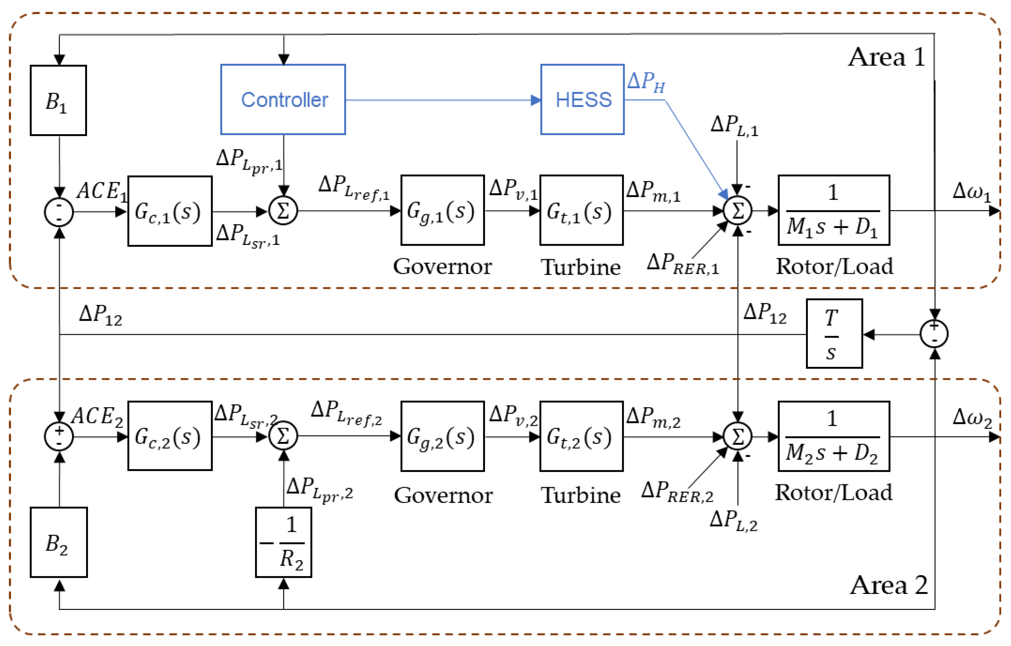
Figure 1. Block diagram of the two-area power system with hybrid energy storage system (HESS) support. M 1 and M 2 are the inertia constants, and D 1 and D 2 the damping coefficients of each area. B 1 and B 2 denote the frequency bias coefficients of Area 1 and Area 2, respectively. T represents the tie-line synchronizing coefficient and R 2 is the droop characteristic of Area 2. P H is the power injected by the HESS. Further details regarding the transfer functions and the remaining variables are provided in Section 2.
Energies 18 04728 g001
Figure 2. Block diagram of the HESS. The battery branch is represented by a first-order dynamic element with time constant τ b and its state of charge deviation Δ S O C B obtained from the battery power Δ P B through the conversion constant K e , B . Similarly, the supercapacitor branch is modeled with a time constant τ s c and SOC deviation Δ S O C S C computed using K e , S C . Both dynamics are combined to provide the total power support of the hybrid energy storage system. Further details regarding the transfer functions and the remaining variables are provided in Section 2.
Energies 18 04728 g002
Figure 3. Membership functions of the fuzzy-logic controller of state of charge of the batteries.
Energies 18 04728 g003
Figure 4. Block diagram of the two-area power system highlighting the integration of the proposed controller with the HESS in Area 1. The controller determines the reference powers of the battery and the supercapacitors, whose combined response defines the total HESS power injection Δ P H . Δ P L p r , 1 denotes the compensated power signal sent by the controller to the conventional generation unit (CGU) in Area 1. Parameter definitions are the same as in Figure 1, and further details regarding the transfer functions are provided in Section 2.
Energies 18 04728 g004
Figure 5. Layered architecture of the neuro-fuzzy controller. The input variables are denoted as e 1 and e 2 . The nodes labeled π correspond to product operations used in the evaluation of fuzzy rules. The “Normalization” block ensures that the firing strengths of the rules are scaled consistently before aggregation. The terms r i , j represent the rule outputs after normalization, where i indicates the input combination and j the rule index. The summation node Σ combines the normalized outputs, yielding the final controller output u .
Energies 18 04728 g005
Figure 6. Block diagram of supercapacitor control system. The input signal corresponds to the frequency deviation, from which the required power for virtual inertia ( P v i ) and primary frequency regulation ( P r p ) are obtained. The total required power ( P S C , d ) is processed through a limiter to ensure bounded action. The neuro-fuzzy controller N F S C further adjusts the participation factor α t according to the operating conditions. Further details regarding the controller design and variable definitions are provided in Section 3.
Energies 18 04728 g006
Figure 7. Membership functions of the neuro-fuzzy controller N F S C . The upper plot corresponds to the input variable normalized supercapacitor demanded power ( Δ P ¯ S C , d ), and the lower plot to the input variable supercapacitor state-of-charge deviation ( Δ S O C S C ). The linguistic values are defined in Section 3.3.1.
Energies 18 04728 g007
Figure 8. Block diagram of battery control system. The signal 1 α t represents the complementary participation with respect to the supercapacitor, while β t denotes the battery participation factor determined by the neuro-fuzzy controller N F B . This controller processes the input variables to adjust the battery contribution according to the operating conditions. Further details of the control strategy and variable definitions are provided in Section 3.
Energies 18 04728 g008
Figure 9. Membership functions of the neuro-fuzzy controller N F B . The upper plot corresponds to the input variable normalized battery demanded power ( Δ P ¯ B , d ), and the lower plot to the input variable battery state-of-charge deviation ( Δ S O C B ). The linguistic values are defined in Section 3.3.2.
Energies 18 04728 g009
Figure 10. Frequency response of Area 1 for Scenario 9.
Energies 18 04728 g010
Figure 11. Rate of change of frequency (ROCOF) in Area 1 for Scenario 9.
Energies 18 04728 g011
Figure 12. Frequency response of Area 2 for Scenario 9.
Energies 18 04728 g012
Figure 13. Power delivered by the ESS for Scenario 9.
Energies 18 04728 g013
Figure 14. Power delivered by the HESS using the proposed method for Scenario 9.
Energies 18 04728 g014
Figure 15. Rate of change in battery power for Scenario 9.
Energies 18 04728 g015
Figure 16. Frequency response of Area 1 during primary and secondary regulation for Scenario 9.
Energies 18 04728 g016
Figure 17. Frequency response of Area 1 for Scenario 10.
Energies 18 04728 g017
Figure 18. Frequency response of Area 1 for Scenario 11.
Energies 18 04728 g018
Figure 19. Power delivered by CGU for Scenario 10.
Energies 18 04728 g019
Figure 20. Power delivered by CGU for Scenario 12.
Energies 18 04728 g020
Figure 21. Frequency response of Area 1 for Scenario 12.
Energies 18 04728 g021
Figure 22. Frequency response of Area 1 for Scenario 13.
Energies 18 04728 g022
Figure 23. Δ S O C B for Scenario 13.
Energies 18 04728 g023
Table 1. The rule base of the fuzzy-logic controller of state of charge of the batteries.
P ¯ d , B
NBNM2NM1NSZEPSPM1PM2PB
Δ S O C B PBNBNM2NM1NSZEZEZEZEZE
PMNBNM2NM1NSZEPSPM1PM2PB
PSNBNM2NM1NSZEPSPM1PM2PB
ZENBNM2NM1NSZEPSPM1PM2PB
NSNBNM2NM1NSZEPSPM1PM2PB
NMNBNM2NM1NSZEPSPM1PM2PB
NBZEZEZEZEZEPSPM1PM2PB
Table 2. The rule base of the neuro-fuzzy controller N F S C .
P ¯ v i , t
NBNM2NM1NSZEPSPM1PM2PB
Δ S O C S C PB000001.001.001.001.00
PM20.250.330.501.001.001.001.001.001.00
PM10.500.671.001.001.001.001.001.001.00
PS0.751.001.001.001.001.001.001.001.00
ZE1.001.001.001.001.001.001.001.001.00
NS1.001.001.001.001.001.001.001.000.75
NM11.001.001.001.001.001.001.000.670.50
NM21.001.001.001.001.001.000.500.330.25
NB1.001.001.001.0000000
Table 3. The rule base of the neuro-fuzzy controller N F B .
P ¯ B , d
NBNM2NM1NSZEPSPM1PM2PB
Δ S O C B PB000001.001.001.001.00
PM30.250.330.501.001.001.001.001.001.00
PM20.500.671.001.001.001.001.001.001.00
PM10.751.001.001.001.001.001.001.001.00
PS1.001.001.001.001.001.001.001.001.00
ZE1.001.001.001.001.001.001.001.001.00
NS1.001.001.001.001.001.001.001.001.00
NM11.001.001.001.001.001.001.001.000.75
NM21.001.001.001.001.001.001.000.670.50
NM31.001.001.001.001.001.000.500.330.25
NB1.001.001.001.0000000
Table 4. Parameters of the conventional generation units and the hybrid energy storage system. Per-unit values are defined on a power base of 20 MW and an energy base of 20 MWh.
ParameterValue (p.u.)ParameterValue (p.u.)
τ g , 1 0.5 τ g , 2 0.3
τ t , 1 0.2 τ t , 2 0.6
D 1 0.6 D 2 0.9
H 1 5.0 H 2 4.0
R 1 0.05 R 2 0.0625
B 1 20.6 B 2 16.9
k i , 1 0.1 k i , 2 0.3
τ b 0.5 τ s c 0.05
Δ P m , n o m 5.0 P s 2.0
P H , m a x 0.15 E H 0.496
E B 0.04 E S C 12 × 0.0008
Table 5. Simulation scenarios for inertial response and primary regulation.
Scenario Δ P L , 1 (p.u.)PRER (%)
10.510
20.520
30.540
41.010
51.020
61.040
71.510
81.520
91.540
Table 6. Summary of the simulation results of inertial response and primary regulation.
ScenarioStrategyITSEISEITAEIAENadir
1Without ESS0.000540.000060.353360.03206−0.00374
Only BESS0.000530.000050.354190.03186−0.00299
SC-VI/BESS-PR0.000530.000050.354220.03186−0.00299
Proposed method0.000540.000050.355950.03157−0.00219
2Without ESS0.000540.000060.353140.03209−0.00396
Only BESS0.000530.000050.354030.03183−0.00298
SC-VI/BESS-PR0.000530.000050.354080.03183−0.00298
Proposed method0.000540.000050.355780.03155−0.00219
3Without ESS0.000550.000060.352690.03217−0.00456
Only BESS0.000530.000050.353710.03177−0.00296
SC-VI/BESS-PR0.000530.000050.353810.03177−0.00296
Proposed method0.000530.000050.355460.03153−0.00219
4Without ESS0.002160.000230.706730.06412−0.00748
Only BESS0.002140.000210.708420.06369−0.00594
SC-VI/BESS-PR0.002140.000210.708490.06369−0.00595
Proposed method0.002180.000210.717590.06347−0.00439
5Without ESS0.002170.000230.706280.06419−0.00792
Only BESS0.002130.000210.708090.06362−0.00590
SC-VI/BESS-PR0.002130.000210.708220.06362−0.00593
Proposed method0.002180.000210.717250.06343−0.00438
6Without ESS0.002210.000240.705380.06433−0.00913
Only BESS0.002120.000210.707480.06348−0.00581
SC-VI/BESS-PR0.002130.000210.707710.06347−0.00587
Proposed method0.002170.000210.716580.06337−0.00437
7Without ESS0.004860.000511.060090.09618−0.01122
Only BESS0.00490.000521.063810.09774−0.00977
SC-VI/BESS-PR0.004920.000531.064160.09788−0.00986
Proposed method0.00490.000471.074880.09542−0.00658
8Without ESS0.004880.000521.059410.09628−0.01187
Only BESS0.00490.000521.063090.09775−0.00993
SC-VI/BESS-PR0.004930.000531.063830.09804−0.01011
Proposed method0.004890.000471.074410.09537−0.00657
9Without ESS0.004970.000551.058070.0965−0.01369
Only BESS0.004910.000541.061680.09835−0.01085
SC-VI/BESS-PR0.004970.000551.063330.09873−0.01100
Proposed method0.004880.000471.073480.09526−0.00656
Table 7. Energy delivered by the ESS and CGU during inertial response and primary and secondary frequency regulation.
ScenarioStrategyOnly Primary RegulationPrimary and Secondary Regulation
E B E S C E H E M P H , m a x P M , m a x E B E S C E M
1Without ESS0000.00017300.061509000.003699
Only BESS0.00017400.00017400.05207100.00085600.002844
SC-VI/BESS-PR0.0001730.0000010.00017400.05191700.0008560.0000010.002844
Proposed method00.0001750.00017500.04389300.0004840.0003710.002847
2Without ESS0000.00017300.063515000.003699
Only BESS0.00017400.00017400.0518400.00085700.002844
SC-VI/BESS-PR0.0001730.0000010.00017400.05152400.0008550.0000010.002844
Proposed method00.0001760.00017600.04388200.0004840.0003710.002847
3Without ESS0000.00017300.068575000.003699
Only BESS0.00017500.00017500.05134300.00085800.002843
SC-VI/BESS-PR0.0001730.0000030.00017500.05065700.0008550.0000030.002843
Proposed method00.0001770.00017700.04397600.0004850.0003710.002847
4Without ESS0000.00034600.123019000.007400
Only BESS0.00034800.00034800.10367800.00171200.005689
SC-VI/BESS-PR0.0003460.0000020.00034800.10352100.0017110.0000020.005689
Proposed method0.0000410.0003090.0003500.08775200.0013270.0003830.005692
5Without ESS0000.00034600.127031000.007399
Only BESS0.00034900.00034900.10303900.00171300.005689
SC-VI/BESS-PR0.0003460.0000030.00034900.10271500.0017100.0000030.005689
Proposed method0.0000410.0003090.00035100.08771800.0013280.0003830.005692
6Without ESS0000.00034700.137151000.007399
Only BESS0.00035100.00035100.10167200.00171500.005688
SC-VI/BESS-PR0.0003450.0000060.00035100.10095500.0017090.0000060.005688
Proposed method0.0000420.0003100.00035300.08788300.0013290.0003840.005691
7Without ESS0000.00051900.184528000.011100
Only BESS0.00051100.00051100.13905900.00255800.008534
SC-VI/BESS-PR0.0005080.0000030.00051100.1389500.0025540.0000030.008534
Proposed method0.0001880.0003350.00052300.13160900.0020820.0003870.008720
8Without ESS0000.00051900.190546000.011099
Only BESS0.00051300.00051300.13898300.00255800.008534
SC-VI/BESS-PR0.0005060.0000050.00051100.13872400.0025520.0000050.008534
Proposed method0.0001890.0003360.00052500.13155400.0020830.0003870.008719
9Without ESS0000.00052000.205726000.011099
Only BESS0.00051200.00051200.13882900.00255800.008532
SC-VI/BESS-PR0.0004990.0000120.0005100.13803800.0025440.0000120.008532
Proposed method0.0001910.0003360.00052700.13179800.0020850.0003870.008718
Table 8. Degradation metrics during inertial response and primary and secondary frequency regulation.
ScenarioStrategy C a v g C r m s C p e a k D o D E F C d Δ P B d t p e a k D M
( × 10 3 % )
1Only BESS0.1914840.2596491.0414230.0171270.0085640.0572130.046195
SC-VI/BESS-PR0.1913290.2593291.0383470.0171130.0085570.0538590.046142
Proposed method0.1082020.1385770.2835760.0096780.0048390.0012910.020387
2Only BESS0.191580.2597381.0368070.0171360.0085680.062380.046229
SC-VI/BESS-PR0.1912720.2590931.0304780.0171080.0085540.0538170.046122
Proposed method0.1082720.1386530.2837120.0096840.0048420.0012920.020406
3Only BESS0.1917690.2599481.0268630.0171530.0085760.0873280.046294
SC-VI/BESS-PR0.1911580.2586311.0131370.0170980.0085490.0537030.046083
Proposed method0.1084140.1388050.283980.0096970.0048490.0012920.020445
4Only BESS0.3828590.5191212.0735680.0342450.0171220.1109010.12468
SC-VI/BESS-PR0.3825210.5184632.0704180.0342140.0171070.1055670.124522
Proposed method0.2966980.3763650.7900420.0265380.0132690.0049890.086522
5Only BESS0.3830760.5193192.0607720.0342640.0171320.1190980.124781
SC-VI/BESS-PR0.3824040.5179852.0543050.0342040.0171020.1053060.124468
Proposed method0.2968730.3765460.7904020.0265540.0132770.004990.086596
6Only BESS0.3835020.5197912.0334380.0343020.0171510.1601260.12498
SC-VI/BESS-PR0.3821740.5170522.0190910.0341830.0170920.1047290.124361
Proposed method0.2972230.3769060.791120.0265850.0132930.0049840.086742
7Only BESS0.571880.7720812.7811720.0511520.0255760.165070.221575
SC-VI/BESS-PR0.5711540.7705762.7789930.0510870.0255430.1563370.221172
Proposed method0.4655320.5997351.3388390.0416390.020820.0142090.164996
8Only BESS0.5720810.7720952.779660.051170.0255850.1762440.221686
SC-VI/BESS-PR0.5705810.768932.7744770.0510350.0255180.1517690.220854
Proposed method0.4657890.6000161.338940.0416620.0208310.0142540.165127
9Only BESS0.5718620.7707482.7765830.051150.0255750.2336150.221565
SC-VI/BESS-PR0.5688630.7642762.760760.0508820.0254410.1315570.219901
Proposed method0.4663090.6005861.3398540.0417090.0208540.0143410.165391
Table 9. Summary of the sensitivity values for load power changes.
ScenarioStrategy S I T S E S I S E S I T A E S I A E S n a d i r
2Without ESS1.50231.47831.00001.00021.0000
Only BESS1.50231.52381.00000.99940.9898
SC-VI/BESS-PR1.50231.52381.00010.99940.9949
Proposed method1.50461.52381.00791.00521.0000
8Without ESS2.49772.52171.00000.99980.9975
Only BESS2.60092.95241.00271.07291.3661
SC-VI/BESS-PR2.62913.04761.00421.08201.4098
Proposed method2.48622.47620.99591.00711.0000
Table 10. Summary of the sensitivity values for changes in PRER.
ScenarioStrategy S I T S E S I S E S I T A E S I A E S n a d i r
4Without ESS0.00920.0000−0.00130.00220.1111
Only BESS−0.00940.0000−0.0009−0.0022−0.0136
SC-VI/BESS-PR−0.00940.0000−0.0008−0.0022−0.0067
Proposed method0.00000.0000−0.0009−0.0013−0.0046
6Without ESS0.03690.0870−0.00250.00440.3056
Only BESS−0.00940.0000−0.0017−0.0044−0.0305
SC-VI/BESS-PR0.00000.0000−0.0014−0.0047−0.0202
Proposed method−0.00920.0000−0.0019−0.0019−0.0046
Table 11. Simulation scenarios for SOC control.
Scenario Δ P L 1 (p.u.) Δ S O C 0 Spinning Reserve for Primary Regulation
100.10−0.275Yes
110.10−0.275No
120.15−0.325Yes
130.15−0.325No
Table 12. A summary of the simulation results of SOC control.
ScenarioSOC Control
Strategy
ITSEISEITAEIAE Δ S O C e n d
10Sigmoid Function0.00220.00020.71670.0634−0.27539
Fuzzy Logic0.00220.00020.71630.0633−0.27538
Neuro-Fuzzy0.00220.00020.71660.0634−0.27540
11Sigmoid Function0.00220.00020.72040.0636−0.27540
Fuzzy Logic0.00220.00020.71840.0636−0.27538
Neuro-Fuzzy0.00220.00020.71660.0634−0.27540
12Sigmoid Function0.00490.00051.07520.0954−0.3259
Fuzzy Logic0.00490.00051.07550.0954−0.32555
Neuro-Fuzzy0.00490.00051.07450.0954−0.32636
13Sigmoid Function0.00750.00061.33690.1125−0.32625
Fuzzy Logic0.00960.00081.51380.1238−0.3259
Neuro-Fuzzy0.00590.00051.18830.1027−0.32658
Table 13. A summary of the storage technology costs for each strategy.
Strategy E B
(MWh)
E S C
(MWh)
C B
(kUSD)
C S C
(kUSD)
C H
(kUSD)
Only BESS0.9920130.9440130.944
SC-VI/BESS-PR0.9880.04130.416105.12235.536
Proposed method0.80.192105.6504.576610.176
Disclaimer/Publisher’s Note: The statements, opinions and data contained in all publications are solely those of the individual author(s) and contributor(s) and not of MDPI and/or the editor(s). MDPI and/or the editor(s) disclaim responsibility for any injury to people or property resulting from any ideas, methods, instructions or products referred to in the content.