1. Introduction
In recent years, the aerospace industry has been concentrating on developing more and more environmentally friendly engines—hybrid, electric, and optimized for low-fuel-consumption combustion engines. The main difficulties are cost-effectiveness, aerodynamics, and mass reduction. There have been concepts of modifying the cycle using heat exchangers directly in the flow path, such as intercoolers and recuperators, or regenerators. Intercoolers are coolers which are most often put between the booster and HPC or between compressor stages, using bypass air or fuel to lower gas temperature. A recuperator is used to extract heat from hot exhaust gases to increase the temperature of gas entering the combustion chamber. The combination of both heat exchangers allows for a significant reduction in fuel consumption and harmful NOx emissions through lowering temperatures and minimizing energy needed to heat the air–fuel mixture for combustion (higher efficiency).
The growing focus on energy efficiency, fuel economy, and environmental sustainability in the aviation industry has sparked renewed interest in advanced thermal management strategies for aeroengines. The key to this evolution is the integration of heat recovery systems such as intercoolers, recuperators, and cooled cooling air heat exchangers (CCAHX). These technologies aim to optimize thermodynamic cycles, reduce fuel consumption, and lower emissions while maintaining or improving engine performance. A thorough review of the recent and foundational literature in this field reveals various methodologies and design philosophies for implementing these systems across different engine types and operating conditions.
The foundation for recuperative gas turbine applications was established in the work of McDonald [
1], who discussed the initial limitations of adopting recuperators in industrial gas turbines. Although their use remained constrained due to concerns about structural integrity and cost, McDonald highlighted their growing importance in defense applications, where weight and volume constraints are crucial. The paper emphasized that technological advancements, particularly from defense programs, would likely make recuperators viable for broader applications, thus paving the way for contemporary interest in this field. However, McDonald’s analysis remained largely qualitative and did not explore performance implications under aviation-specific constraints, leaving room for further quantitative evaluation.
Building on this foundational perspective, a more specific approach was taken by Xu et al. [
2], who proposed an intercooled recuperated turbofan engine optimized for aviation use. Their study introduced a systematic, multidisciplinary optimization method to balance spatial constraints and performance efficiency. The novel configuration achieved significant reductions in specific fuel consumption and demonstrated the feasibility of complex heat recovery integration in compact aero-engine designs. While their method is rigorous, the study focuses on a single engine configuration without sensitivity analysis across different aircraft types or operating profiles, limiting the generalizability of their conclusions.
Further extending this concept, Chen et al. [
3] conducted a techno-economic and gas path analysis of intercooled recuperated turbofan engines. Their energy–exergy-based evaluation revealed a 23.53% reduction in fuel exergy flow and a 2.58% improvement in exergy efficiency compared to conventional cycles. Additionally, real-time diagnostic capability for fault propagation within heat exchangers was demonstrated using gas path analysis, with minimal error margins under steady and transient conditions. Despite these strengths, the study does not address how maintenance or fault management strategies would scale with engine complexity, nor does it evaluate the impact of diagnostics on long-term operational cost.
Complementing the above works, Saavedra and Cadarso [
4] introduced a propulsion concept that recovers exhaust heat from the core engine stream and reheats it using a pressure-gain device. This heated stream is reintegrated with the bypass flow to boost engine performance. Their parametric analysis via multi-objective optimization led to an 11% reduction in fuel consumption, confirming the efficacy of advanced thermal cycle augmentation. However, the practical integration of such reheat mechanisms into existing engine architectures remains largely unexplored, particularly concerning reliability and control complexity under varying flight conditions.
To support these system-level innovations, advancements in heat exchanger technology have been crucial. Lee et al. [
5] presented a detailed experimental characterization of novel cross-corrugated plate heat exchangers for aero-engines. By varying geometry and flow configurations, high-resolution Nusselt number and friction factor correlations were established. Although the data are valuable, the study does not extend to system-level performance implications or the manufacturability of such heat exchangers within typical aero-engine design envelopes.
Similarly, Salpingidou et al. [
6] assessed a circular-tube heat exchanger for a low-pressure ratio heli gas turbine. Using detailed CFD modeling and thermodynamic simulations, they demonstrated a 10.6% improvement in thermal efficiency and a 9.3% reduction in fuel consumption compared to non-recuperative counterparts. Yet, the narrow application scope (heli gas turbine) and simplified assumptions regarding real-world mission variability constrain its relevance to broader engine types.
In the context of rotorcraft propulsion, Zhang and Gümmer [
7] reviewed high-temperature heat exchanger technologies for turboshaft engines. Their work categorized suitable configurations (e.g., tubular, plate-fin, and primary surface) and identified their readiness levels. The study underscored how previous market limitations, such as low fuel prices and insufficient material technologies, previously hindered deployment. However, today, socio-economic drivers and improved materials justify the resurgence of recuperators in rotorcraft applications. Still, the review stops short of evaluating the thermodynamic trade-offs or design challenges of applying these technologies across rotorcraft with differing mission profiles.
In the field of alternative fuels, Yazar et al. [
8] examined the exergetic and environmental performance of hydrogen- and AVGAS-fueled piston-prop engines across LTO phases. The hydrogen-powered variant demonstrated superior exergy efficiency (up to 78.4%) and lower specific fuel consumption (0.101 kg/kWh), particularly during the approach phase. Moreover, environmental and sustainability metrics confirmed the favorable ecological profile of hydrogen. Nonetheless, the study focuses only on steady-state flight modes, omitting transient effects and practical constraints related to hydrogen storage and aircraft integration.
Patrao et al. [
9] explored the use of hydrogen for internal engine cooling via stator vane heat exchangers in high-speed compressors. CFD simulations showed a modest core air temperature drop (9.5 K) and up to 0.8% specific fuel consumption improvement in cruise conditions. While promising, the analysis is limited to isolated cooling effects and does not quantify trade-offs in weight, complexity, or integration feasibility within multi-stage engine systems. Their further study [
10] evaluated compact heat exchangers for hydrogen-fueled intercooling and recuperation. The work emphasized the high heat capacity and thermal conductivity benefits of hydrogen and suggested that compactness and effectiveness can be achieved with miniaturized components. However, the trade-offs between compactness, pressure loss, and system-level integration complexity remain unresolved, highlighting a need for more holistic engine modeling.
Finally, Yang et al. [
11] investigated the use of CCAHX in geared turbofan engines, where fuel was used as a thermal sink for turbine blade cooling. Their coupled model and optimization strategy led to small but measurable gains in performance (0.064% SFC reduction, 0.366% thermal efficiency gain). While demonstrating a creative use of fuel heat capacity, the performance gains are relatively marginal and come at the cost of increased system complexity and limited operational flexibility.
The purpose of this work is to investigate and propose thermodynamic cycle modifications in turbofan engines through the integration of intercooling and recuperation, to enhance efficiency and reduce fuel consumption. Unlike many previous studies that focus either on theoretical analyses or examine these technologies separately, this work combines a comprehensive literature review with original conceptual design and optimization studies applied to both narrow-body and wide-body aircraft engines. A key novelty lies in the simultaneous application of intercoolers and recuperators within one propulsion system and the evaluation of their combined effects under realistic operating constraints. Additionally, this work references selected innovative concepts from existing patents and literature, such as the use of cryogenic liquid hydrogen as a multifunctional coolant, to illustrate the broader technological context and ongoing research trends. From a practical perspective, the results provide valuable insights for improving the energy efficiency of turbine engines, contributing to advancements in sustainable aviation and supporting innovation in energy systems, aerospace propulsion, and industrial thermal management.
In conclusion, these studies collectively highlight the growing technological maturity and diverse applications of heat recovery systems in aviation propulsion. From classic recuperators to advanced hydrogen-cooled vanes and integrated CCAHX modules, the literature reflects a multifaceted evolution driven by thermodynamic performance, sustainability goals, and architectural innovation. Despite persistent challenges, particularly regarding pressure losses, space constraints, and fault tolerance, the consistent gains in efficiency, diagnostics, and emissions reduction strongly advocate for the continued development and integration of heat recovery systems in next-generation aero-engines.
2. IRA Engines
Turbine engines utilize the energy of flowing gases to generate power and, in the case of turbojets and turbofans, thrust. Modeling the gas flow process and its thermodynamic cycle can have beneficial effects of improving efficiency, which can lead to, for example, a reduction in assembly weight. One way to enhance efficiency is by using heat exchangers—intercoolers and recuperators.
An intercooler (IC) is a heat exchanger placed between compressors (e.g., IPC and HPC) or compression stages. The goal is to decrease the working fluid temperature before entering the following compressor module. It allows for lower operating temperatures and less work having to be put in to reach the desired pressure ratio. It also results in denser air and more oxygen for the combustion process. It enables lower SFC and/or higher power or thrust through higher engine efficiency [
12,
13].
A recuperator is a heat exchanger used for recovering waste heat (waste heat ranges up to around 57% of heat extracted from fuel) from very hot exhaust gases. This heat is transferred to the working fluid before entering the combustor. It yields an increase in cycle efficiency resulting from modified energy balance (see
Figure 1) [
13,
14].
ICs and recuperators may be used separately or together, boosting potential efficiency benefits. As technology advances and the need for energy efficiency optimization grows, the development of turbine engines with intercoolers and recuperators has become an area of intensive research and innovation in mechanical engineering regarding usability in energy systems and aviation. Heat exchangers should be designed to maximize efficiency in terms of both heat transfer and flow dynamics.
3. Aerospace Applications
The implementation of heat exchangers for turbojet and turbofan engines involves multiple design requirements to be met. These include choice of high-temperature resistant materials, maximizing the heating efficiency, minimizing airflow losses, keeping the mass of the system low, and limited space. The last two points are the main reasons for IRA engines not being widely commercialized. The issue primarily concerns cost-effectiveness and other alternatives researched by engine manufacturers, such as open-fan engines or geared turbofans. The R&D and service costs are remarkably high and could pose a significant risk to manufacturers. The process of optimizing the HE system must account for the fuel cost, having to outweigh fuel lost due to higher aircraft mass and worsened aerodynamics.
Standard IRA engine concepts can ultimately be reduced to a single design [
15]. The high-pressure core airflow after IPC is diverted into the heat exchanger (intercooler), cooled by bypass airflow, and returned to HPC. A recuperator is placed in the aft part of the engine. Heat from exhaust gases is extracted. Flow from HPC has to be diverted to the recuperator, heated, and turned back (posing difficulties) to the combustion chamber.
The aforementioned example of intercooler implementation is presented in
Figure 2. A standard turbofan layout is used with a modified air flow path. Just after IPC, the core flow is redirected to an intercooler, mostly placed at the inner part of the bypass, and cooled by its high mass flow of air. The hot air is then returned to the core and goes through HPC and onwards. This layout does not allow for a more efficient fully counter-flow heat exchanger or may be used only partially. Cross-flow and parallel-flow HEXs are applicable. A conventional design allows for easier development and/or modification of the current engine architecture.
4. Patents
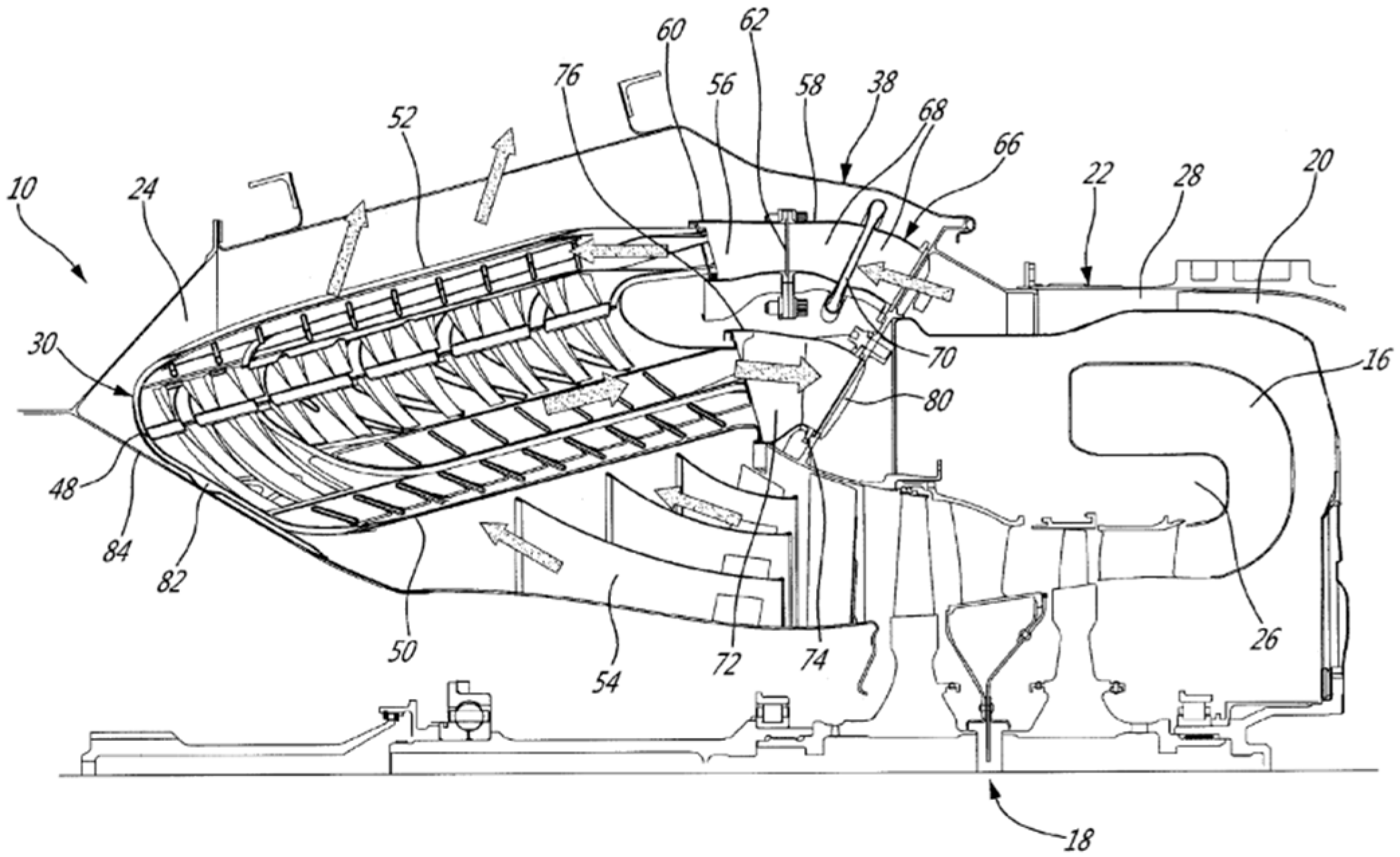
The US patent 2016/0305324 A1 presents a non-conventional engine design setup—compressor, turbine, combustor from the front (with double reversed flow) instead of a normal compressor, combustor, turbine configuration [
16,
17]. The core flow (A, see
Figure 3) enters LPC and goes through the intercooler. It then reverses direction and advances towards IPC and HPC (LPC + IPC to IC to HPC setup is also possible). In the schematic, additional flow reversal is shown for core flow exiting the intercooler due to space constraints. Afterwards, the flow passes through the recuperator (flow D), combustion chamber, and subsequent turning passage, directing exhaust flow to the hot side of the recuperator. Then, exhaust gases are expelled from the engine.
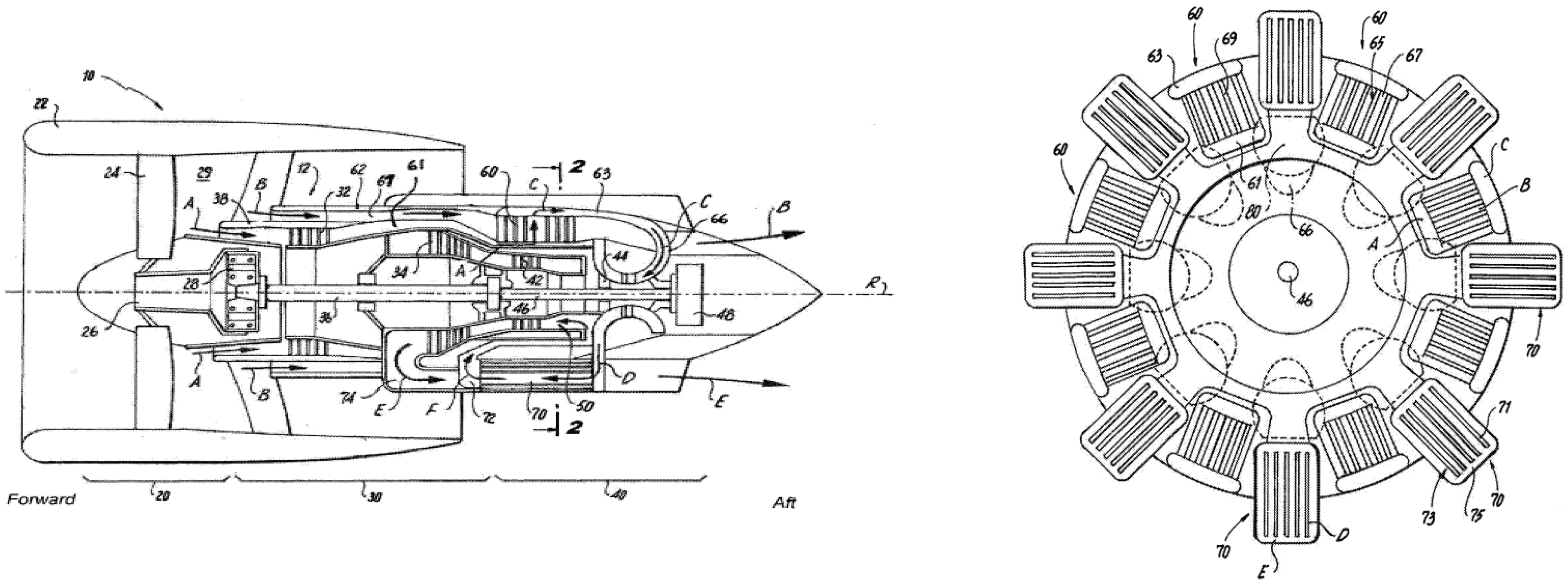
The other proposal is presented in US9395122B2 patent [
18]. The difference arises from the direction of flow through the nozzle and recuperator. The flow is curved into a spiral after passing the turbine (circumferential velocity component is increased), increasing the time for heat exchange, and diffused throughout the HEX (see
Figure 4). The whole toroidal recuperator is split into separate modules, allowing for cheaper manufacturing and easier maintenance. This concept improves the overall heat exchange.
Another design idea stems from the 2000s US6092361A patent (
Figure 5). It describes a recuperator for gas turbine engines [
19]. After exiting the compressor (radial compressor is presented), working fluid passes through ribbed tubes placed in the exhaust diffuser. Ribs are used to increase the heat exchange surface area. There are multiple of those tubes placed perpendicular to the exhaust diffuser. The solution may significantly lower the mass and size of the engine and minimize air flow resistance. The configuration presented in the drawing (with reversed order of the turbines, that is, HPC driving turbine is placed second in the flow path) seems beneficial for turboshaft and turboprop engines because of the compact compressor and turbine placement. Also, coaxial nested dual shafts are not necessary.
In conclusion, proposed HEX patents and solutions are similar, as all mention air-to-air HEXs. Some of the foregoing designs are distinguished by their high efficiency, albeit at the cost of increased weight and size. Conversely, lighter solutions raise concerns about their achievable efficiency and overall benefits. The concepts presented pertain primarily to recuperators. However, the implementation and design of the heat exchanger can also be adapted for use in intercoolers.
Despite the growing interest in thermal management solutions for aircraft engines, existing studies often focus on either intercooling or recuperation in isolation, without exploring their combined effects under realistic operating constraints. Additionally, many prior works rely on simplified models or neglect the performance differences across various aircraft classes. There is also limited research that translates patented or conceptual designs. This study addresses these gaps by conducting a constrained optimization for both narrow-body and wide-body aircraft engines, evaluating the integrated application of intercooling and recuperation. It further bridges the gap between theoretical designs and practical engine performance by assessing system-level impacts on thrust, fuel consumption, and emissions.
5. Present Studies
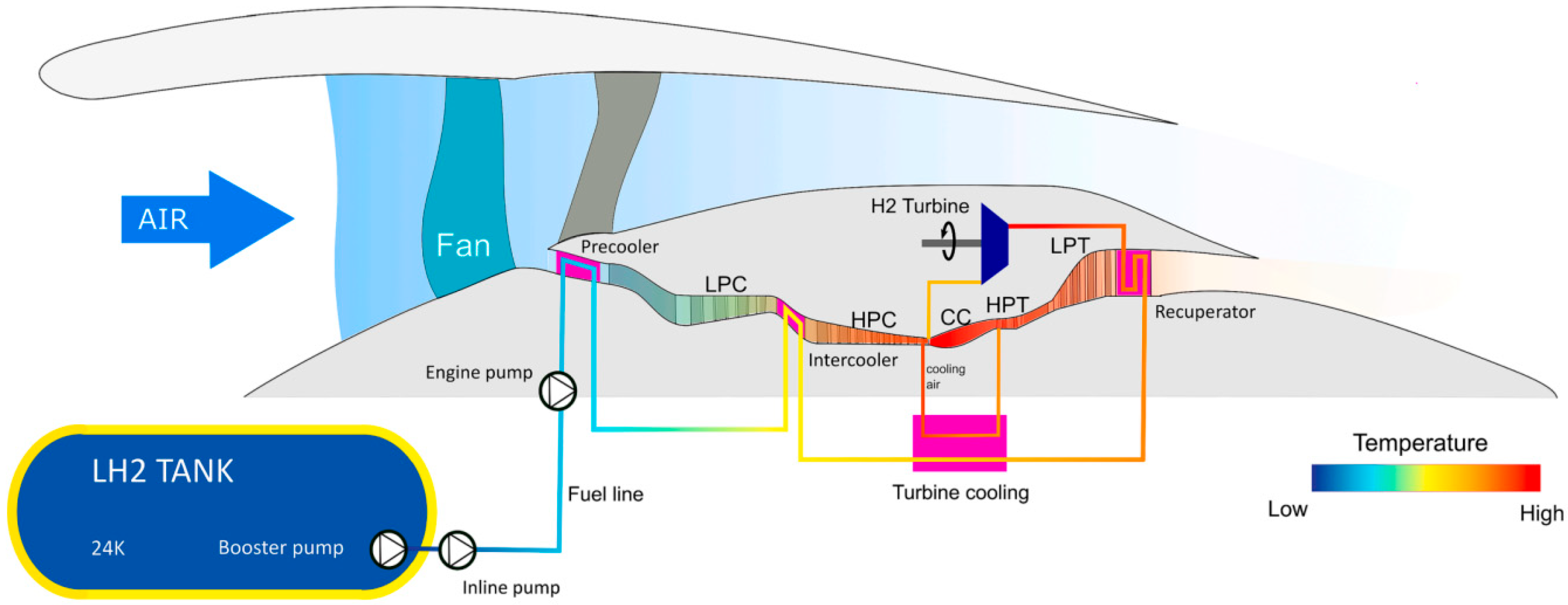
A paper ‘Compact heat exchangers for hydrogen-fueled aero-engine intercooling and recuperation’ is quite different in terms of HEX application, in which hydrogen is used as fuel [
10]. A solution is proposed to utilize cryogenic liquid hydrogen for cooling in the IC recuperator, as well as to cool the turbine and add another cooler between the fan and entry to the LPC (a precooler, see
Figure 6). Although it comes with multiple challenges, such as hydrogen storage and delivery systems, cryogenic storage temperature, and safety concerns, liquid hydrogen can be an excellent cooling medium for engines’ HEXs. Two geometrical variants were analyzed. The shorter AR4 has slightly higher total pressure loss and flow non-uniformity, whereas the optimal AR6, is around 1.5 times longer, meaning higher mass and larger dimensions in the engine. Advanced duct shape optimization, detailed CFD study with meshing explained, was presented. Compared to the baseline non-IRA engine, results show that the HEX pressure drop requires an increase in pressure ratio to maintain constant OPR. An increase in BPR due to higher core-specific power is possible. The AR6 variant saw a 5.3% SFC reduction on cruise for the IRA engine, but only 2.7% for the intercooled engine. Overall SFC reductions stand at 5.3% to 7.7% and 2.7% to 3.9%, respectively. The NO
x emission results show a possible reduction from 23% to 37%. It is noted that the SFC decrease is caused mostly by having already pre-heated fuel. The paper briefly reflects on HEX material and potential issues such as icing or damage, and leakage of hydrogen in hot parts of the engine. Many variants may apply, such as a conceptual IRA engine that can have 2 HPC stages less due to the lower compression work needed. Although weight significantly increases compared to the baseline hydrogen-fueled engine, overall fuel burn reduction could reach 5.5% on an over 5500 km mission.
The use of liquid hydrogen as both coolant and fuel offers significant thermodynamic advantages. However, its practical implementation is highly complex. It requires cryogenic storage tanks (temperature of −252 °C), advanced insulation systems, and strict safety measures. These introduce major engineering and operational challenges. In addition, integrating such systems into existing aircraft may increase weight and maintenance demands (because of the energy density [MJ/l]: Hydrogen (LH2)—10.03; Aircraft kerosene (Jet A)—36.66). Hydrogen-based configurations highlight the potential for maximum cycle efficiency. However, their feasibility is limited by current technological maturity and infrastructure requirements.
Missirlis et al. [
20] developed a numerical tool for optimizing heat exchanger (HEX) performance in intercooled recuperated aero-engines, balancing heat transfer efficiency with pressure loss. Using a porosity model, complex HEX geometries were simplified as porous media, enabling accurate yet computationally efficient simulations. Three recuperator concepts—NEWAC, STARTREC, and CORN—were evaluated via CFD-integrated cycle analysis. STARTREC and CORN showed improved flow uniformity over NEWAC, with CORN achieving a 13.1% reduction in specific fuel consumption (SFC) and 5% mass savings. STARTREC halved the HEX weight and reduced SFC by 9.1%. Performance gains stemmed from optimized, axisymmetric designs, with the final selection dependent on mission-specific trade-offs.
Complementing this, Salpingidou et al. [
21] compared three cycle layouts as follows: conventional recuperative (CR), alternative recuperative (AR), and staged heat recovery (SHR). CR performed best at low pressure ratios (PR), while AR became more efficient at high PR and HEX effectiveness. SHR offered flexible optimization, achieving up to 56.3% thermal efficiency under ideal conditions. However, AR and SHR face integration challenges in aero-engines due to limited space and inter-turbine HEX constraints. While concepts like STARTREC and CORN mitigate some issues, AR still results in ~13% higher SFC and 11% lower efficiency than CR. Only select SHR configurations slightly outperformed CR, with ~0.6% efficiency gains.
The reviewed publications explore advancements in thermodynamic cycles and heat recovery for gas turbines and aero-engines, aiming to improve efficiency, reduce fuel consumption, and lower emissions. They examine various configurations, conventional, alternative, staged recuperation, and intercooling combinations, and assess their performance impacts. Integrating recuperation and intercooling enhances thermal efficiency, reducing SFC and emissions, though higher HEX effectiveness can sometimes reduce work output. Pressure losses in HEXs remain a key trade-off, affecting net performance. Implementation in aero-engines faces challenges due to space, weight, materials, and high upfront costs, despite long-term savings. Further development is needed in optimizing design parameters, geometry, and materials. Concepts like STARTREC and CORN help address these hurdles and represent progress toward compact, effective HEXs for aviation. Overcoming these barriers through innovation and testing is essential for advancing sustainable aviation and power generation.
6. Original Analysis
6.1. Methodology
An analysis was conducted as part of independent work on the application of heat exchangers in turbofan engines. IRA engine calculations were conducted to evaluate the benefits of cycle modification using intercooler and recuperator heat exchangers. The following two turbofan variants were analyzed: a 140 kN engine (typical for narrow-body aircraft, e.g., CFM56-5C2) and a 360 kN engine (for wide-body aircraft, e.g., Trent 1000). Key parameters are listed in
Table 1. A baseline (see the layout on
Figure 7) was established by using parameters from different engines in similar thrust ratings and adjusting them to match the desired take-off thrust. The goal was to assess changes in TIT, SFC, and nitrous oxides emissions, while maintaining similar thrust, using GasTurb 14 (GasTurb GmbH, Aachen, Germany). Similar methodology for modeling the thermodynamic processes in the turbofan engine is present in Kurzke et al. [
22]. A non-mixed dual-shaft turbofan model was used to determine the baseline, non-mixed tri-shaft intercooled-recuperated turbofan model.
The analysis involved optimization with constraints to ensure adequate thrust output. Burner exit temperature was the sole variable, aiming for the lowest SFC on cruise altitude. Net thrust was constrained within ±5% of the target (the baseline at 11 km of altitude) to maintain comparable performance. Optimization used a random search algorithm built into the software. To reduce the number of variants, when both the IC and the recuperator are used, HEX effectiveness remains the same for both HEXs.
6.2. Wide-Body Aircraft Turbofan
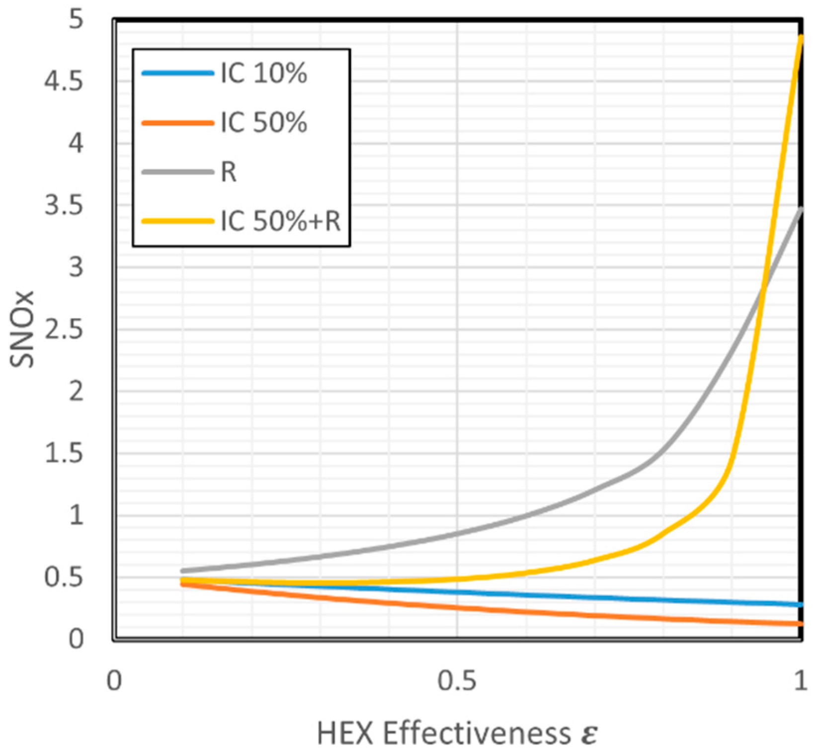
Figure 8 and
Figure 9 present the results of the optimization process for a turbofan engine intended for wide-body aircraft. Key performance parameters, including the turbine inlet temperature (TIT), specific fuel consumption (SFC), and NO
x severity index, were analyzed to evaluate the effectiveness of combined intercooling and recuperation.
6.3. Results and Discussion
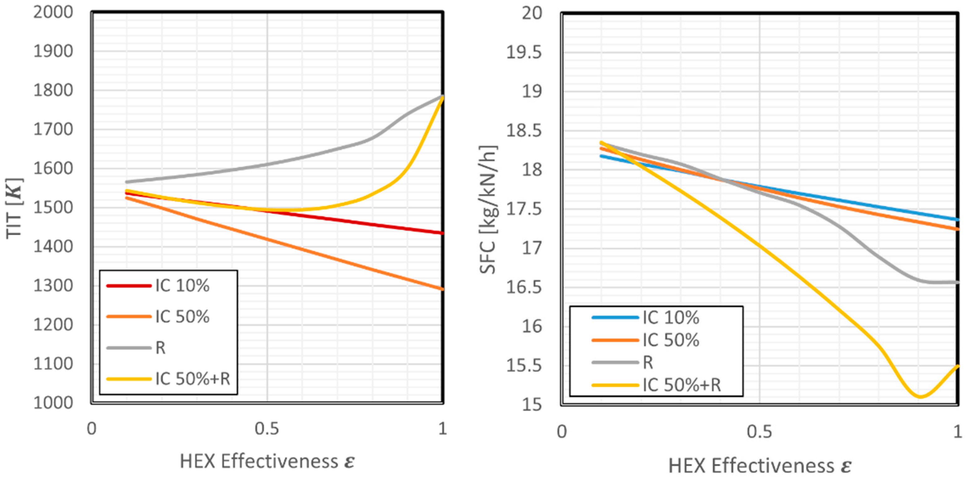
TIT optimization results for various HEX effectiveness ε are shown in subsequent diagrams. The following configurations are presented: an intercooled engine cooled by 10% of bypass air (IC 10%), an intercooled engine cooled by 50% of bypass air (IC 50%), a recuperated engine (R), and an intercooled (50% of bypass air) and recuperated engine (IC 50% + R).
6.3.1. Wide-Body Turbofan Results
In configurations with intercooling only (IC 10% and IC 50%), a monotonic decrease in TIT is observed as ε increases. This behavior results from the reduction in compressor outlet temperature, which in turn decreases the required fuel flow to reach the target turbine inlet conditions.
In contrast, the recuperated configuration (R) demonstrates a continuous increase in TIT with increasing ε. The rise becomes particularly steep as ε approaches the value of 1, driven by the enhanced recovery of thermal energy from the exhaust gas, which raises the combustor inlet temperature and thus the TIT. The combined system (IC 50% + R) exhibits a non-monotonic response: an initial slight decrease in TIT for ε < 0.5 is followed by a rapid increase at higher effectiveness values. This trend reflects the competing thermal influences of intercooling (reducing TIT) and recuperation (increasing TIT), with the latter dominating at high ε. All configurations benefit from increased heat exchanger effectiveness, with SFC decreasing monotonically due to improved thermal efficiency. Among the individual systems, the recuperated engine (R) shows a more pronounced decline in SFC than the intercooling-only variants. However, the most significant reduction is observed for the combined IC 50% + R configuration, where SFC decreases sharply and reaches a minimum around ε ≈ 0.9. Beyond this point, a slight increase in SFC is noted, likely attributable to the associated rise in TIT and potential over-recovery of heat. Configurations incorporating only intercooling (IC 10% and IC 50%) show a modest decline in NOₓ emissions with increasing ε. This trend corresponds to reduced combustor inlet temperatures, which lower thermal NOx formation rates. At 50% HEX effectiveness (IC 50%), TIT drops by 112 K, SFC by 5.9%, and NOx severity index by 51%. Conversely, the recuperated configuration (R) shows an exponential increase in SNOx as ε increases. The elevated combustor inlet and turbine inlet temperatures associated with high heat recovery promote more intensive thermal NOx formation. At 50% effectiveness, maintaining thrust requires a 54 K TIT increase, enabling 6.2% lower SFC. The NOx rises by 86.7%. In the combined system (IC 50% + R), the increase in emissions is more moderate at lower ε but becomes steeper as ε exceeds 0.75. While intercooling provides partial mitigation, the recuperation-driven rise in TIT ultimately dominates, leading to elevated NOx levels. An intercooled-recuperated (IRA) engine allows a 44 K TIT reduction, 9.8% SFC drop, and only 8% higher NOx.
6.3.2. Narrow-Body Aircraft Turbofan
Figure 10 and
Figure 11 illustrate the results of performance optimization for a turbofan engine designed for narrow-body aircraft. The analysis focuses on the effects of intercooling and recuperation or the combined configuration on key parameters such as turbine inlet temperature (TIT), specific fuel consumption (SFC), and NO
x emissions.
6.3.3. Narrow-Body Turbofan Results
Narrow-body turbofan presents with similar relations of parameters, but with smaller slopes (due to lower mass flow and IC cooling). At 50% HEX effectiveness (IC 50%), the SFC reduction reaches about 2.3%, and the NOx emissions decline by more than 40%, while TIT drops by nearly 40 K compared to the baseline. The recuperated engine exhibits a different trade-off. At ε = 0.5, SFC is reduced by around 2.4%, confirming a meaningful improvement in thermal efficiency. However, this benefit comes at the cost of significantly increased NOx emissions—by more than 60%—driven by a rise in TIT of approximately 34 K. For the IRA configuration, the SFC is reduced by approximately 5.2%, the most significant improvement among the three configurations. Importantly, NOx emissions also decrease by over 21% compared to the baseline, as the cooling effect of intercooling helps counterbalance the elevated TIT typical of recuperated cycles. The resulting TIT increase is modest, around 9 kelvins.
7. Conclusions
In response to the growing demand for sustainable and thermodynamically efficient propulsion systems in aviation, this study presents a comprehensive review and performance assessment of intercooled recuperated aero-engines (IRA). The findings combine literature insights, conceptual design considerations, and parametric optimization, offering a thorough evaluation of the thermodynamic, environmental, and practical implications of integrating heat exchangers into modern turbofan architectures.
The simultaneous application of intercooling and recuperation within turbofan engines significantly enhances overall thermal efficiency. Specifically, the combined IRA configuration yields a reduction in specific fuel consumption (SFC) of up to 9.8 percent in wide-body aircraft applications. This dual heat exchanger approach benefits from complementary mechanisms, where intercooling reduces compression work and recuperation recovers exhaust heat, leading to marked improvements in cycle performance.
The thermodynamic behavior of intercooling and recuperation exhibits opposing trends concerning turbine inlet temperature (TIT) and nitrogen oxides (NOx) emissions. Intercooling alone causes a monotonic decrease in TIT and NOx formation, while recuperation increases TIT due to preheating of the combustion air, which promotes thermal NOx generation. However, when combined, these systems enable significant thermal efficiency gains while mitigating excessive temperature rise and pollutant formation, particularly at intermediate levels of heat exchanger effectiveness (ε between 0.5 and 0.9).
Cycle optimization results vary by engine class. For narrow-body aircraft configurations, the IRA system achieves a 5.2 percent reduction in SFC and over 21 percent reduction in NOx emissions, despite lower cooling capacity and mass flow rates. These results emphasize the necessity of mission-specific design strategies that consider engine size, operating conditions, and performance requirements.
The results from the original analysis align with the results seen in other studies. The decrease in SFC for moderate effectiveness is seen below 10 percent. The NOx emissions also see similar reduction, but they are affected by more variables—a PR, burner exit temperature, and water-to-air ratio. A direct comparison is not possible as other works could have used a different metric for NOx emission evaluation. The TIT reduction cannot be directly compared with other works, as this approach of optimizing burner temperature is new.
An innovative approach involves the use of cryogenic liquid hydrogen as a multifunctional heat sink. This strategy offers up to 7.7 percent SFC reduction and 37 percent NOx emission abatement during cruise conditions by utilizing hydrogen for intercooling, recuperation, and turbine cooling. While the benefits are significant, the complexity of hydrogen storage, distribution, and safety must be carefully addressed.
A fundamental design trade-off exists between heat exchanger effectiveness, pressure loss, and added engine mass. Higher effectiveness improves thermal efficiency but can result in increased pressure losses and structural penalties. Therefore, a multi-objective optimization approach is essential, utilizing advanced simulation tools and compact heat exchanger topologies such as porous-media modeling or modular configurations.
Recuperation, although beneficial for fuel economy, tends to increase NOx emissions significantly, with up to 86.7 percent growth observed at high effectiveness. Intercooling partially offsets this trend in IRA systems, but additional mitigation strategies such as lean-burn combustors or catalytic aftertreatment may be required to meet future emission regulations.
Several patented and non-conventional design solutions demonstrate feasible integration of heat exchangers into aero-engines. Concepts including spiral flow recuperators, ribbed tubular heat exchangers, and dual-reversed core flows enhance heat transfer while preserving compactness and aerodynamic efficiency. These designs broaden the applicability of heat exchanger technology in both existing and next-generation propulsion systems.
In conclusion, IRA engines represent a promising transitional solution for improving energy efficiency and reducing environmental impact in aviation. Despite challenges in terms of integration, weight, and cost, the thermodynamic benefits are clear. Continued research, innovation, and validation of optimized configurations are essential steps toward the realization of sustainable aviation propulsion systems.
The purpose of the team’s further research is to make a numerical model of the heat exchanger system for a narrow-body aircraft engine. It will be used for this work which is expected to provide its data for determining the efficiency and impact on the performance of an aircraft turbine engine.


