Abstract
Solid-state transformer (SST)-based ultra-fast charging stations (UFCSs) are emerging as a key technology in next-generation electric vehicle (EV) infrastructure, addressing the growing demand for efficient charging. Unlike traditional line-frequency transformers, SSTs offer higher energy conversion efficiency, smaller size, and better scalability. However, challenges such as control complexity and grid stability remain. This review analyzes existing SST topologies (both classical and new) and control methods, discussing their impact on system performance, and finally, it provides an outlook on future technological trends.
1. Introduction
The energy transition in the transportation sector is a core pathway toward achieving carbon neutrality. The U.S. Department of Energy (DoE) has clearly emphasized that reducing transportation energy consumption is a key national strategy for energy independence [1]. Battery Electric Vehicles (BEVs), owing to their superior energy efficiency, have emerged as a promising solution. However, the limitations of conventional charging infrastructure hinder the large-scale adoption of EVs. Line-frequency transformers (LFTs), in particular, not only introduce significant harmonic pollution into the grid but also suffer from large volume and weight. Furthermore, the slow deployment pace of charging stations and fragmented standards continue to impede progress. Against this backdrop, the Solid-State Transformer (SST) has emerged as a transformative solution. By integrating high-frequency isolation and modular power conversion, SSTs offer a 65% reduction in volume and a 3% increase in efficiency compared to LFTs, while enabling direct medium-voltage (MV) grid connection and megawatt-level scalability [2]. The international standard IEC 61851-23:2023 [3] further mandates that charging equipment provide controllable DC output and millisecond-level dynamic protection [4]. SSTs, leveraging high-frequency operation, are uniquely positioned to meet both these requirements and the DoE’s stringent >97% efficiency mandate for power distribution equipment [1], thus laying a technological foundation for next-generation ultra-fast charging infrastructure.
Despite their notable advantages in Ultra-Fast Charging Stations (UFCSs), SSTs still face critical challenges that must be addressed before widespread deployment. MW-level fast charging (1–4.5 MW) in weak grid regions may induce voltage fluctuations and parasitic oscillations, while legacy charging stations lack active stabilization mechanisms to suppress voltage sags caused by sudden load changes. Simultaneously, emerging standards such as the Megawatt Charging System (MCS) remain incomplete, particularly in terms of connector interfaces, thermal management protocols, and grid interaction specifications, resulting in a gap between SST design and practical interoperability requirements. More critically, SSTs are expected to transcend the conventional roles of chargers by providing grid-supportive services such as virtual inertia and dynamic reactive power compensation through advanced control strategies [5]—capabilities essential to ensure stability in renewable-rich power systems. Consequently, it is imperative to systematically investigate the technological bottlenecks of SSTs in topology innovation, real-time control optimization, and grid-interaction coordination. These efforts are key to bridging the gap between theoretical potential and real-world commercialization [1,2,4,5].
This paper seeks to break with the conventions of existing SST reviews in its structural design and content organization, adopting a narrative driven by practical design and application requirements. First, in terms of topology, it moves beyond the constraints of traditional circuit-level classification by establishing a framework built around the following three core objectives: high-efficiency energy conversion, modular scalability, and grid-interaction capability, enabling the quick identification and selection of topologies for specific design needs. On this basis, the evolutionary pathways of these topologies are extrapolated to reveal development trajectories and inspire new design concepts. Second, the review systematically integrates a layered control architecture, mapping both classical and emerging SST control strategies to three levels—hardware-level regulation, grid-service management, and system-level coordination—along with an analysis of “control under complex operating conditions” for weak-grid and fault scenarios, quantifying stability boundaries and enhancing the engineering scalability of control strategies. Finally, an engineering reliability analysis is presented, addressing the efficiency and lifespan bottlenecks of high-frequency power devices caused by thermal management, and proposing a “thermal–electrical–lifetime” co-optimization approach. The potential of AI-enabled reliability control in power electronics is also explored. Overall, the work forms a closed-loop knowledge system of “design guidelines—implementation templates—deployment assurance”, providing both a theoretical benchmark and a technical roadmap for the standardized deployment of SST-UFCSs.
2. Functional Demand-Driven Evolution of SST Topologies
2.1. High-Efficiency Energy Conversion Demand
2.1.1. Classical Topologies and Their Bottlenecks
With the rapid proliferation of EVs, the “15-min recharge” target for UFC imposes revolutionary requirements on charging infrastructure in terms of power density, energy-conversion efficiency, and grid-interaction capability [6]. Conventional LFTs combined with multi-stage power-conversion architectures suffer from large physical size, high losses, and pronounced harmonic interference, making them unsuitable for the 350–900 kW class of UFCSs. Industry standards—such as CHArge de MOve (CHAdeMO) and Guobiao Recommended Standards (GB/T) now identify high power (>350 kW), a wide voltage window (200–1000 V), and low losses as key design metrics [7]. Consequently, the evolution of the SST topology must prioritize high power density, low loss, and dynamic impedance matching to satisfy the combined demands of multi-gun parallel charging, efficient energy delivery, and active grid support. This paper systematically reviews the technological evolution of SST topologies and their optimization trajectories for UFC applications.
As shown in Figure 1, classical SST topologies are generally classified by the number of conversion stages into single-, two- and three-stage variants as follows: a single-stage topology is the simplest, yet the absence of a DC link precludes power-factor correction (PFC) and bidirectional power flow, severely limiting its suitability for high-power scenarios; a two-stage topology introduces an intermediate DC link that partially mitigates harmonic distortion, but the complex multilevel configuration and soft-switching difficulty at high voltage still constrain gains in efficiency and reliability, and the lack of a high-voltage DC (HVDC) link hinders the integration of distributed energy resources; a three-stage topology, building on the first two, further incorporates HVDC and low-voltage DC (LVDC) links and thus offers clear advantages, including support for vehicle-to-grid (V2G) operation, a marked reduction in total harmonic distortion (THD to <5%), and convenient integration of photovoltaic and energy-storage systems, thereby steering charging stations toward higher efficiency and lower carbon emissions [8,9,10].
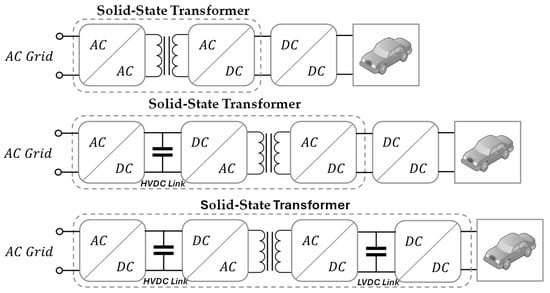
Figure 1.
Structural evolution of solid-state transformer topologies.
Although the three-stage topology delivers significant structural improvements, current SST systems must still overcome key technical bottlenecks in both the front-end AC/DC and back-end DC/DC stages. As shown in Table 1, on the AC/DC side, high power density demands have led to the widespread deployment of multilevel topologies such as the Neutral-Point-Clamped (NPC) and Cascaded H-Bridge (CHB) in medium- and high-voltage applications owing to their excellent voltage balancing and modular characteristics. To reduce energy losses, Vienna rectifiers, buck-type rectifiers, and interleaved three-phase Pulse-Width Modulation (PWM) solutions exploit soft-switching techniques and high-frequency devices to raise conversion efficiency. And, for grid interaction, active PWM rectifiers and similar topologies are attracting attention because of their control flexibility and bidirectional capability [5,7,8].

Table 1.
Comparison of front-end AC/DC topology characteristics.
Meanwhile, as shown in Table 2, back-end DC/DC modules exhibit a diverse set of topology choices as follows: the Phase-Shifted Full-Bridge (PSFB) topology offers structural simplicity but limited light-load performance; the LLC resonant converter supports high-frequency, high-efficiency operation yet lacks true bidirectionality; and the DAB has become the key option for its bidirectional power flow and control flexibility, though its soft-switching window narrows under light-load conditions [9,15,18].

Table 2.
Comparison of back-end DC/DC topology characteristics.
Based on the above analysis, the subsequent sections of this review will focus on resonant converters, dual active bridge (DAB) converters, and hybrid structures, highlighting their technical advantages and research progress in high power density, low-loss operation, and grid interaction.
2.1.2. High-Frequency Innovative Topologies
Driven by the demand for efficient energy conversion, resonant converter topologies in SST are gradually emerging as key solutions for UFCS systems. As shown in Figure 2, the early TAIPEI rectifier combined a two-switch discontinuous conduction mode (DCM) boost stage with a virtual neutral point to achieve low input THD and soft commutation, yet its low-voltage, two-stage configuration imposed clear limits on efficiency and power density [23].
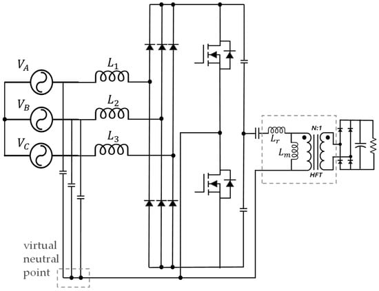
Figure 2.
TAIPEI rectifier.
To accommodate medium-voltage operation, subsequent research merged the rectification and resonant stages into a single-stage design. As shown in Figure 3, the three-phase HBC integrated with an LLC resonant tank [24] strings multiple modules to share voltage stress and delivers system efficiencies above 97.5%, exemplifying the trends toward structural integration and loss reduction.
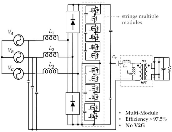
Figure 3.
The three-phase HBC integrated with an LLC resonant tank.
Most of these schemes, however, remain restricted to unidirectional power flow, limiting their potential for interaction-oriented UFCS use cases such as V2G. The work by Xu et al. [25] breaks this barrier by proposing a single-stage AC/AC converter that couples a half-bridge LLC resonant network with SiC AC switches, as shown in Figure 4. Eliminating the intermediate DC link, the system achieves an efficiency of over 98.5% through full-load zero volt switching (ZVS) and adaptive dead-time control, while natively supporting bidirectional energy transfer in hardware.
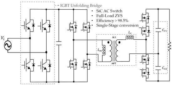
Figure 4.
Single-stage AC/AC converter that couples a half-bridge LLC resonant network with SiC AC switches.
In addition, the three-phase triple-voltage LLC (T2-LLC) topology in Figure 5 utilizes structural design to double the three-phase input voltage, effectively reducing the number of modules and enhancing power density. It also realizes inherent bidirectional power flow through fixed duty-cycle open-loop control, thereby balancing control simplification with high efficiency [26].
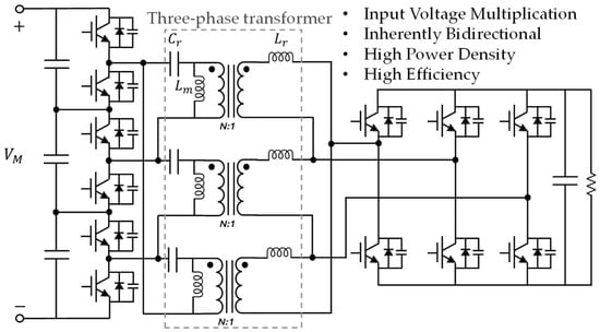
Figure 5.
T2-LLC resonant converter.
In summary, resonant-topology SSTs for UFCSs are advancing toward high-frequency soft switching, deeper structural integration, bidirectional control, and modular adaptability, thereby offering robust support for the combined spatial, efficiency, and interactivity requirements of next-generation charging stations.
As the most representative high-frequency isolated bidirectional power conversion solution in SST systems, the DAB topology has continuously evolved in both structural and application aspects since its inception. Zhao et al. systematically traced its early trajectory and classified DAB variants into multi-bridge, multi-port, and modular-nested forms, underscoring the converter’s high scalability in power rating and functional expansion [27]. Recent studies have focused on medium-voltage extreme-fast-charging scenarios, further highlighting the central role of DAB and its derivatives in SST-UFCS architectures, while placing stricter demands on control and reliability [28]. Overall, DAB evolution follows two distinct directions—structural simplification and multi-port integration.
In the former, the Hybrid DAB, as shown in Figure 6, shares legs between half- and full-bridge sections, sharply reducing the switch count, raising power density, and mitigating power pulsations, though secondary-side ZVS still needs improvement [29].
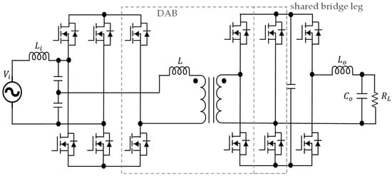
Figure 6.
Hybrid DAB with arm-sharing for reduced component count.
The IMHB-DAB in Figure 7 employs a half-bridge matrix rectifier to realize one-step conversion from medium-voltage AC to low-voltage DC, cutting intermediate losses and device stacking while boosting output capability, yet current-distribution optimization remains essential for engineering practice [30].
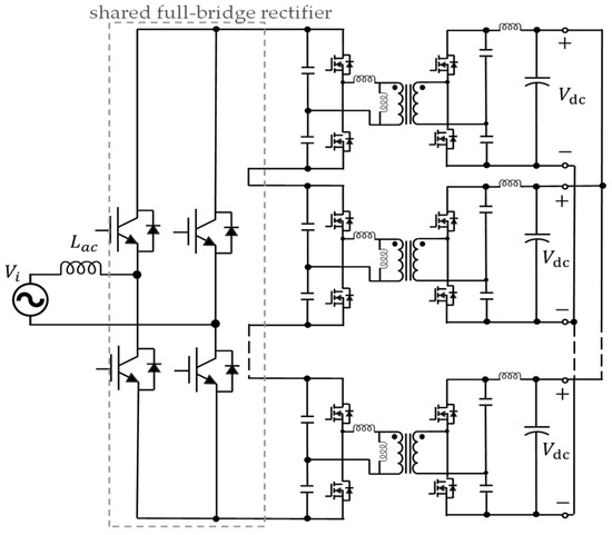
Figure 7.
IMHB-DAB enabling single-stage isolated AC-DC conversion.
In the latter, the quad active bridge (QAB) shown in Figure 8 uses a four-winding transformer and a series-input/parallel-output arrangement to provide multiple voltage levels, greatly improving magnetic utilization and port scalability for multi-vehicle simultaneous charging [31].
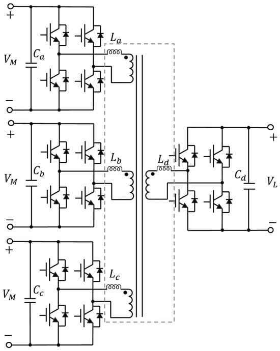
Figure 8.
QAB with multi-winding transformer for primary-side integration.
On the other hand, a triple-active-bridge (TAB) topology employs a three-port magnetically coupled structure, as shown in Figure 9, enabling integrated and coordinated connections among the vehicle, grid, and energy storage systems within a single module. This approach significantly simplifies the conventional multi-port fast-charging systems, which typically require multiple parallel DAB modules. Centered around a three-winding high-frequency transformer and combined with three bridge-arms forming the power conversion channels, the TAB topology exhibits excellent port expandability and structural compactness, thereby enhancing the utilization of magnetic components and providing greater flexibility in control [32,33].
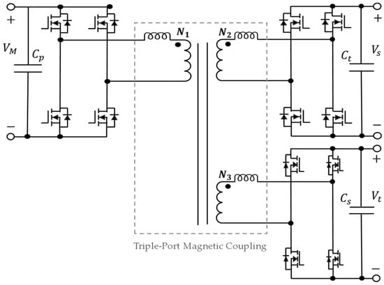
Figure 9.
TAB as a three-port hub for secondary-side power management.
The foregoing evolution paths show that the DAB topology is being continuously refined around device- and magnetic-core sharing, multi-port parallel support, and enhanced soft-switching capability; this trend provides a vital technical foundation for ultra-fast-charging systems to attain high performance, standardized compatibility, and modular design.
In addressing the demand for efficient energy conversion in ultra-fast charging stations, hybrid-structured topologies are exhibiting multi-path evolutionary trends. As illustrated in Table 3, early representative work can be traced back to the 15 kV Intelligent Universal Transformer (IUT) proposed by Lai et al. [34]. This design employs a three-level power conversion structure consisting of an active front-end rectifier, LLC resonant converter, and hybrid-switch inverter, achieving system-level efficiency optimization under natural cooling conditions. Innovatively, it introduced parallel inverter structures combining SiC devices and IGBTs, along with dynamic voltage regulation mechanisms, thus providing an initial paradigm for subsequent SST architectures tailored for parallel fast-charging applications. Subsequently, Liang et al. [35] presented a non-modular, high-voltage direct-coupled hybrid topology integrating a three-level boost (TLB) PFC with an Active-Neutral-Point-Clamped Dual-Active-Bridge (ANPC-DAB). Their design achieved reduced voltage stress on SiC components and a more compact system. Although lacking redundancy for scalability, this work demonstrated the feasibility of structural integration for medium-to-high power density applications. Lee et al. [36] further introduced a multi-module hybrid scheme based on an Input-Series Output-Parallel (ISOP) structure, enhancing redundancy and harmonic adaptability to the grid through phase-shift modulation and module decoupling. However, this approach also increased control complexity and hardware overhead. Focusing on flexible output and magneto-electric coordination, Nair et al. [37] proposed embedding balancing windings within Quad-Active-Bridge (QAB) medium-frequency transformers to achieve the self-balancing of power flows. Combined with a wide-voltage direct-coupled structure adaptable to various electric vehicle types, this solution provided a novel optimization pathway for system adaptability and reliability. In industrial-level ultra-fast charging applications, Zhu et al. [20] proposed a medium-voltage direct-coupled modular SST architecture integrating cascaded H-bridge rectifiers and three-level CLLC resonant converters. This design realized highly efficient energy conversion from grid input to vehicle output, marking significant commercial progress in the application of hybrid-structured topologies.

Table 3.
Comparison table of hybrid topology characteristics.
2.2. Modularity and Scalability Demand
As station power climbs to 350–500 kW, UFCS installations must retain high efficiency, easy maintenance, and future expandability under high-power, highly dynamic, multi-vehicle conditions [38]. Table 4 lists the grid interaction capabilities, structural characteristics, and loss performance of typical modular topologies, providing a fundamental reference for subsequent comparative analyses of technological pathways. The evolution of modular SST topologies can be summarized into five main lines—hardware minimalism, voltage-platform standardization, multi-port power scheduling, module-control co-design, and compact single-stage high-efficiency schemes. The representative solutions and their challenges in elastic expansion and control standardization are reviewed sequentially below.

Table 4.
Comparison of four classic modular topologies.
First, along the hardware-minimal route, the transition from modular integrated-active-filter rectifier (mIAFR) to modularized bridge rectifier (mBR) is obvious; although mIAFR improves THD through phase selector switches (PSSs) and injection branches (IBs) modules, the diversity of power modules keeps costs high [39,40,41]. mBR removes PSSs/IBs entirely, retaining only a diode bridge and parallel DAB; cuts device count; and by using ΣΔ-vector algorithms, achieves voltage balancing and reduces THD to below 1% without communication, thereby establishing a low-cost, high power density base for MW-class UFCSs [42].
Second, to satisfy modular and expandable demands, SST topologies continue to evolve; early generation CHB converters connect directly to MV by stacking sub-modules, yet they require DABs with different turn ratios for multiple output voltages, resulting in high customization and maintenance costs [43]; the unified power electronics building block (PEBB)-CHB of Ma et al. [44] only partly alleviates this, still relying on external converters for multi-voltage adaptation. The DHB adds symmetric half-bridges per arm to improve bidirectional efficiency, but battery and port voltages still need an extra DC-DC stage [45]. By contrast, the double-star chopper-cell (DSCC) employs identical 4:1 DAB sub-modules, fixes the LV side at 400 V, and can be series-stacked to 400/800/1.2 kV, eliminating multi-ratio transformers. Three-phase power sharing lowers circulating-current peaks by 70–93%, and 400 V batteries connect directly, though HV insulation and battery aging effects on dynamic balance remain as challenges [46].
Third, in multi-port power scheduling, clustered DAB topologies dominate as follows: The cascaded matrix-based (CMB)-DAB plus power-balance control (PBC) equalizes module voltages and power in real time and supports CC/CV charging curves and V2G [47]. The QAB integrates four bridges through a single multi-winding HF transformer, cutting magnetics to one-third, while extended triangular current modulation (TCM) modulation realizes full-load zero current switching (ZCS) and direct inter-module power exchange [48]. The AC-Link scheme parallels several three-winding transformers, eliminating zero-sequence compensation, reducing DC-link capacitance by about 66%, and allowing plug-and-play expansion [49].
Fourthly, the synergy between modular structures and control strategies is predominantly exemplified by the MMC family. As shown in Figure 10, Figure 11, Figure 12, Figure 13 and Figure 14, MMCs have been extensively utilized in medium-to-high-voltage conversion scenarios due to their modular scalability, high reliability, and excellent waveform quality [50,51]. In SST-based ultra-fast charging applications, although traditional three-stage MMC topologies provide good waveform quality and stability, their power density and system complexity have become notable bottlenecks [52,53]. To address these challenges, researchers have introduced various innovative solutions based on MMC submodule restructuring and power-path optimization, aiming to enhance overall efficiency and power density. For instance, the 2-String 2-Inductor (2S2I) MMC topology in Figure 10 effectively reduces both the number of submodules and the dependence on high-voltage-side capacitors through an innovative series-parallel submodule design and direct integration with high-frequency transformers, significantly reducing losses and system volume. Additionally, this structure decouples the low-frequency grid interaction from high-frequency power transmission via current-fed and differential-mode power transmission paths, thus offering a higher power-density solution suitable for ultra-fast charging scenarios [54].
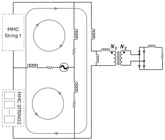
Figure 10.
2S2I MMC topology.
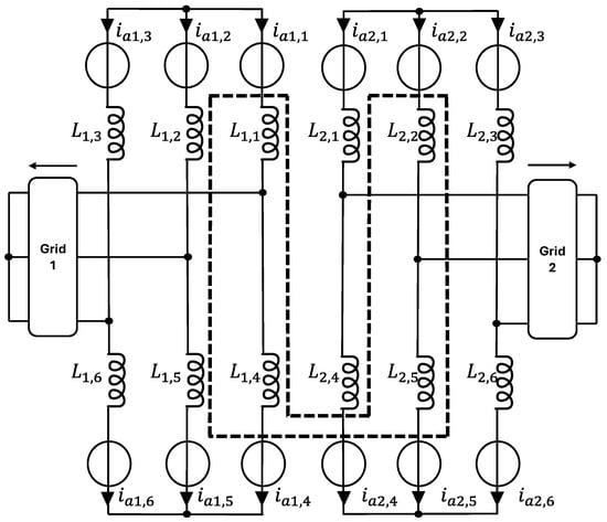
Figure 11.
MMC-SST with magnetically coupled arm inductors.
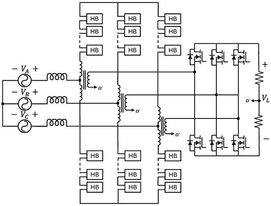
Figure 12.
Arm-reconfigured and magnetically integrated MMC topology.
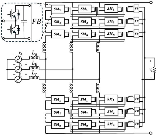
Figure 13.
FM2C-SST topology.
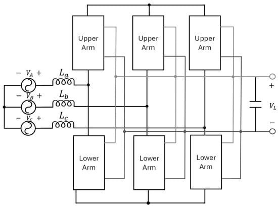
Figure 14.
PSFB/DAB-MMC topology.
Type B MMC topologies replace traditional two-level submodules (SM) with three-level NPC or cascaded half-bridge submodules, markedly reducing the component count. Moreover, the low-voltage DC (LVDC) outputs are realized through series-parallel reconfiguration at the DAB side, enabling multi-voltage outputs [55]. Further advancements in power density have been achieved through magnetically coupled MMCs and bridge-arm reconstruction approaches. As illustrated in Figure 11, these methods utilize single-core magnetic coupling for electrical isolation, enhancing topology compactness and scalability. However, they require introducing multi-frequency energy balancing mechanisms to maintain system stability [56].
As illustrated in Figure 12, Zheng et al. [57] proposed a highly integrated topology that eliminates intermediate DC links via bridge-arm reconstruction and magnetic integration. By directly embedding a medium-frequency transformer into MMC bridge-arms and employing hybrid-frequency modulation control strategies, this topology simultaneously handles low-frequency grid interfaces and medium-frequency power outputs, thus substantially improving device utilization and system compactness.
The FDAB-MMC topology (FM2C-SST) in Figure 13 introduced by Teng et al. [58] achieves horizontal three-submodule magnetic coupling interconnections through four-port dual-active-bridge (FDAB) structures, reconstructing SM capacitors into switched capacitor networks. This approach notably reduces the required capacitance values and naturally suppresses arm circulating currents through ripple self-cancelation, greatly enhancing power density.
Additionally, the PSFB/DAB-MMC solution [59] in Figure 14 employs a hybrid submodule design integrating buffer less capacitor PSFB modules and buffered capacitor DAB modules within the same arm. By dynamically adjusting the voltage of the buffered capacitors in DAB modules, virtual inertia enhancement is achieved, reducing LVDC port voltage drops during load transients, thus significantly improving system resilience under disturbances. This makes it particularly suitable for charging scenarios characterized by high volatility.
Overall, these innovative structural developments clearly demonstrate that the optimization of submodule structures combined with improved power transmission path design substantially enhances the performance and adaptability of multilevel MMC topologies in ultra-fast charging applications.
Finally, compact high-efficiency single-stage schemes converge on the integrated SST (I-SST) and soft-switching SST (S4T): I-SST [60] targets modularity limits caused by multi-voltage needs, using a high frequency (HF) transformer for compact isolation, a 12-pulse rectifier to suppress input harmonics, and uniform DABs for flexible expansion, while eliminating DC-link capacitors and controlling output by duty ratio. Nevertheless, leakage-inductance compensation and transient response without capacitors need further study. The scheme adopts an input-series output-parallel (ISOP) layout and single-stage soft switching, reduces main devices through magnetizing-inductor DC links and optimized leakage placement, suppresses electromagnetic interference (EMI), and increases power density. Its multi-port capability integrates photovoltaics (PV), storage, and fast-charge loads, though dynamic management of leakage energy still requires refinement [61,62].
Hence, modular SST evolution has progressed from minimalist standardized power units to voltage-platform standardization and flexible multi-port scheduling and is now integrating control and hardware into compact single-stage topologies, thereby targeting high power density, scalability, and low maintenance in future UFCS deployments.
2.3. Grid Interaction Capability Demand
The preceding sections have provided a systematic analysis of the structural evolution and performance characteristics of high-frequency innovative topologies, hybrid structures, and modular SST architectures. Under ideal grid conditions, all of these topologies can achieve high-efficiency energy conversion and multi-port power management. However, in practical ultra-fast charging deployments, complex grid environments—such as low short-circuit ratio (SCR), high harmonic distortion, and voltage imbalance—are common, placing higher demands on topology robustness, control complexity, and grid connection stability [62].
Overall, under harsh grid conditions featuring low SCR, high harmonic distortion, and voltage imbalance, hybrid topologies—particularly those equipped with active front ends—exhibit superior comprehensive performance. Their core advantage lies in the active rectifier at the front end, which can directly achieve low input-current harmonics through active control and provide proactive grid-voltage support, thereby effectively improving power quality at the point of common coupling and enhancing system stability. In contrast, DAB/LLC systems with passive front ends (e.g., multi-pulse rectifiers) face significant high input-harmonic challenges; even modular DAB architectures with active front ends must address complex interactions and stability risks introduced by multi-module parallel operation in weak grids, which substantially increases control complexity. Under ideal grid conditions, DAB and LLC topologies can fully leverage their high-efficiency or bidirectional capabilities [7,63].
To address these differences and limitations, various grid-interface topologies based on voltage or current injection have been proposed in SST-UFCS systems to enhance grid connection performance and power-quality control capability. In SST-UFCS systems, various current and voltage injection topologies have been proposed to enhance grid interaction and power quality. The Flying Converter Cell (FCC) presented by Hartmann et al. [63] adopts a centralized architecture, incorporating two half-bridges and a three-level leg to inject harmonic currents into the non-conducting phase via bidirectional switches, thereby improving current waveform quality and power factor. It features high efficiency and simplified control, making it suitable for relatively steady power conditions. In contrast, the mIAFR described by Makoschitz et al. [40] employs parallel submodules based on half-bridge or full-bridge configurations to construct distributed injection paths, offering enhanced flexibility and fault tolerance in dynamic fast-charging environments. The partial power processing approach proposed by Iyer et al. [64] introduces a series-connected PSFB module between the battery and the DC bus, which only regulates the voltage difference rather than the full power path. This structure reduces component stress and enables electrical decoupling from medium voltage (MV)-side disturbances, demonstrating practical potential in extreme fast-charging applications.
3. SST Control Strategies and Grid Interaction
Early SST control strategies primarily relied on PI/PR dual-loop control to regulate LV and MV current, thereby improving distribution network power quality [65,66]. To cope with highly dynamic loads and weak grids, more advanced methods, such as model predictive control (MPC) and virtual synchronous machine (VSM) techniques, have recently been introduced [67]. The work by Liserre et al. [68] categorizes the ST control framework into three levels—inner, middle, and outer—corresponding, respectively, to hardware-level regulation, grid-service management, and system-level coordination. The following discussion adopts this structure to review typical implementations and key technical developments of each control layer within SST-UFCS applications.
3.1. Inner Control Layer
Firstly, as shown in Table 5, for the front-end AC/DC converter, the literature reports widespread use of dual-loop PI control [9,69], MPC [69,70], sliding-mode control, fuzzy control, and space-vector PWM (SVPWM) [18], which together offer fast dynamic response, reduced harmonic distortion, and enhanced robustness.

Table 5.
Comparison of AC/DC converter control methods.
Secondly, regarding the control strategies for the subsequent-stage rectifier, as indicated in Table 6, mainstream control methods primarily include phase-shift control [18,69] and dynamic DC-link adjustment [18]. These control strategies effectively enhance the stability of output voltage and system efficiency, ensuring the reliable operation of UFCS systems.

Table 6.
Comparison of DC/DC converter control methods.
Building on this foundation, the inner control layer—serving as the core of fast hardware-level regulation in SST systems—is primarily responsible for precise current/voltage control, modulation strategy optimization, realization of ZVS/ZCS soft switching, and suppression of power fluctuations. This paper, considering the specific system requirements of SSTs in UFCS scenarios, categorizes the inner control strategies into the following three key objectives: soft-switching modulation optimization, power decoupling and modeling, and ripple suppression mechanisms. It systematically reviews the representative mechanisms and engineering implementation pathways for each category, while analyzing their adaptability and scalability under conditions of high power density, rapid charging/discharging dynamics, and multi-port power management.
3.1.1. Modulation Optimization and Soft-Switching Control
For the single-stage, isolated AC/DC half-bridge matrix DAB (MB-DAB), the work by Saha et al. [71] systematically analyzes the complete set of soft-switching modulation modes. It identifies the power boundaries of six types of ZCS/ZVS modes and establishes a dual-objective analytical optimization framework using leakage inductance , transformer turn ratio n, and switching frequency as independent variables. An optimal design selection is achieved through a normalized objective function expressed as follows:
where represents power density, denotes efficiency, is a normalized metric combining both efficiency and power density, and is the total number of design candidates. Building on this, the same group derives closed-form expressions for the pulse width and phase shift , achieving real-time modulation without look-up tables or iterative computation; This scheme maintains near full-cycle ZVS within a certain load range and significantly reduces the computational burden of control [72]. Together, these studies establish an integrated “offline η–ρ optimization–online analytical modulation” methodology. It should be noted, however, that the experimental validation remains limited to single-phase kilowatt-scale prototypes, whereas scalability to multi-port, three-phase, high-power systems as well as compatibility with system-level coordination still requires verification.
Jean-Pierre et al. [73,74] introduce a triple-phase-shift (TPS) dynamic optimization framework that employs particle-swarm and Lagrange algorithms to adjust DAB duty cycles and phase shifts in real time, as illustrated in Figure 15, thereby extending the ZVS window, lowering switching losses, and pushing system efficiency to more than 97%. A region-segmented loss model partitions DAB operation into low-, medium-, and high-power zones and incorporates the non-linear loss characteristics of the high-frequency transformer, enabling precise load matching. To address multi-module coordination, improved Lyapunov control and voltage balancing strategies suppress inter-module voltage imbalance in cascaded H-bridges, reducing grid-current THD to below 1.6% and cutting filter losses. Experimental results identify switching loss as the dominant energy sink and demonstrate that system-level loss decomposition can guide both theoretical design loops and hardware implementation for compact, high power density, low harmonic charging stations, thus accelerating the practical deployment of SSTs in extreme-fast-charging scenarios.
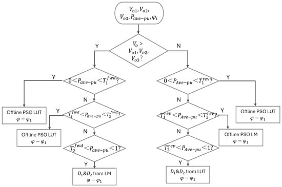
Figure 15.
Optimal closed-loop control.
Beyond the analytical and optimization-based approaches above, TCM control has recently been introduced into SST high-frequency links to realize ZVS or ZCS across the full load range, thereby reducing switching loss and raising overall efficiency. Costa et al. [48] apply TCM to the QAB topology, modulating the current slope of each bridge arm to achieve both port-to-port power regulation and soft-switching optimization, which suits multi-port voltage-matching and energy-sharing systems. Rothmund et al. [75] extend the concept to integrated TCM (iTCM), inserting an LC loop between rectifier legs to secure full-cycle ZVS for the main switches and isolate harmonic currents, a strategy particularly advantageous for high-efficiency rectifiers built with medium-voltage SiC devices. These contributions demonstrate the broad applicability and energy-efficiency benefits of TCM-based control, ranging from multi-port DC–DC regulation to high-voltage AC–DC rectification in SST-UFCS systems.
3.1.2. Decoupling and Model Reconstruction Control Strategies
To address the issues of system coupling and control complexity in SST-based UFCS applications, various decoupling and model reconstruction control strategies have been proposed. Several representative control frameworks are illustrated from Figure 16, Figure 17 and Figure 18.
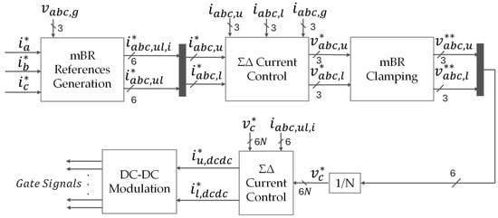
Figure 16.
ΣΔ-vector control method.
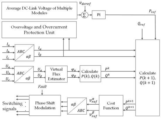
Figure 17.
VF-PDPC control method.
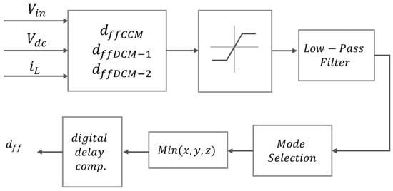
Figure 18.
Hybrid feedforward control for three-Level boost rectifier.
The modular bridge rectifier (mBR) was first regulated by a branch-oriented current-control scheme. However, a mismatch between the number of controlled variables and system degrees of freedom produced control conflicts, degraded dynamic performance, and, because the algorithm required high-bandwidth voltage sensing, made the controller sensitive to grid-impedance variations [42]. To overcome these drawbacks, the ΣΔ-vector control method was introduced. As shown in Figure 16, by applying a Clarke transformation followed by ΣΔ decomposition, the algorithm decouples inter-phase currents and reconstructs the control variables into total and differential components, enabling fully coordinated control within four degrees of freedom. Simulation results demonstrate enhanced robustness and strong tolerance to parameter perturbations. Although the implementation is still limited to unidirectional rectification, the architecture provides a sound basis for future extensions to bidirectional power flow and reactive-power support [76].
As a scenario-specific enhancement of model predictive control (MPC) in the field of power electronics, the work by Lahooti et al. [77], shown in Figure 17, proposes the Virtual-Flux-Based Predictive Direct Power Control (VF-PDPC). Centered on predictive principles, this method reconstructs the grid model using virtual flux to replace direct voltage measurements and combines it with direct power prediction control. By eliminating dependencies on the phase-locked loop (PLL) and current control loops, it achieves fast power decoupling with strong harmonic immunity, significantly enhancing control robustness under highly distorted grid conditions.
To address the issue of degraded damping and reduced system stability in MV SSTs caused by limited high-voltage capacitance in traditional Boost models, as shown in Figure 18, Lee et al. [36] proposed a topology-level equivalent circuit reconstruction method. Their work established an accurate state-space model for a three-level Boost (TLB) rectifier, quantitatively analyzing how halving the output capacitance in MV scenarios affects pole-zero distribution and damping ratios. This approach effectively resolves the adaptation failure of traditional Boost models under highly dynamic MV grid conditions. They further introduced a continuous conduction mode (CCM)/DCM hybrid duty-cycle feedforward strategy to decouple input voltage disturbances, achieving disturbance rejection via dynamic conduction mode switching, complemented by a hardware-based voltage balancing design to eliminate inter-module coupling. The use of passive hardware-level balancing simplifies inter-module interactions and significantly improves compatibility with MV grids. This cost-effective control paradigm offers a practical solution for MV SSTs in ultra-fast charging applications, and the underlying model reconstruction concept can be extended to multi-port, bidirectional power flow scenarios.
3.1.3. Ripple-Suppression and Energy-Buffering Techniques
To mitigate energy fluctuations and DC-link ripples caused by high-power dynamic loads in UFCS systems, numerous inner-layer control strategies have made significant progress in ripple suppression and energy buffering in recent years. Figure 19, Figure 20 and Figure 21 present several typical control block diagrams for ripple suppression and energy buffering. Zhou et al. [78] proposed a real-time control method based on dynamic phase-shift modulation, namely the power fluctuation delivery (PFD) control shown in Figure 19. By extracting the low-frequency fluctuation component of the power entering each MMC sub-module and mapping it to an additional phase-shift command for the DAB, the scheme actively diverts the oscillatory power to the LVdc bus. Without extra hardware, this power-path reconstruction markedly reduces capacitor-voltage ripple and module circulating currents, making the approach well suited to compact, high-power systems.
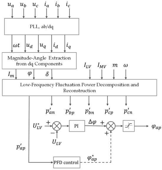
Figure 19.
PFD control method.
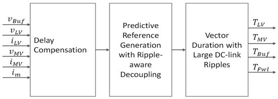
Figure 20.
APD-predictive control.

Figure 21.
Reverse-ripple-injection reference-voltage strategy.
In a related study, the work by Zheng et al. [79] integrates active-power decoupling with predictive (APD) control to form a DC-link energy-regulation framework in which a buffering port absorbs low-frequency ripple while a dynamic-compensation model tackles high-frequency disturbances. As presented in Figure 20, the result is concurrent DC-link stability and fast transient response across multi-module systems, addressing the fine-grained control requirements of medium-voltage, high-switching-speed applications.
Further, to counter the double-line-frequency pulsation in the DC link, the work by Cao et al. [80], shown in Figure 21, introduces a reverse-ripple-injection reference-voltage strategy. By superimposing an equal-frequency, opposite-phase component onto the DAB reference, the controller cancels ripple power propagated from the AC/DC stage. In three-phase systems, constructing 120° phase-shifted ripple-voltage waveforms enable mutual cancelation at the primary-current level, providing an effective ripple-suppression solution for small-capacitor, high power density SSTs.
3.2. Middle Control Layer
As shown in Table 7, at the overall UFCS control level, mainstream control methods include droop control [69,70], zero-sequence circulating current suppression [14], distributed voltage balancing control [13], as well as dynamic pricing response algorithms and coordinated voltage balancing control [18]. All of them aim to enable effective interaction and coordination between charging stations and the power grid.

Table 7.
Comparison of middle-layer control methods.
3.2.1. Power Balancing and Voltage Coordination
To ensure stable operation in modular SST systems, power balancing and voltage coordination have become essential control objectives. Several representative control schemes are illustrated in Figure 8.
In modular SST systems, inevitable inconsistencies in the magnetic component parameters among submodules often lead to uneven power transfer and current distortion on the grid side. To address this, Saha et al. [81] proposed a power balance control (PBC) strategy based on dynamic compensation of the phase-shift angle. By introducing an independent phase-shift correction mechanism for each submodule outside the main voltage control loop, the strategy enables fine-tuned power allocation among submodules without altering the primary control structure. This method demonstrates good stability and scalability under conditions such as hot-swapping and load disturbances. Building on this foundation, the Saha group further proposed a multi-objective optimal analytical balance control (MOC) strategy for CMB-DAB-based single-stage isolated structures to tackle common issues in multi-module topologies, such as parameter deviations and inconsistent dynamic responses [82,83]. As presented in Figure 22, this method constructs a microsecond-level online leakage inductance estimation model based on current peak values and feeds it into the pulse width and phase-shift modulation stages, enabling adaptive compensation for power–ZVS coupling errors. The approach integrates bus voltage regulation, THD constraints, loss balancing, and ZVS range extension into a unified analytical optimization framework, thereby improving both efficiency and system robustness. It is particularly suitable for high power density charging scenarios with stringent requirements on control precision and dynamic performance.
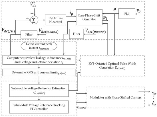
Figure 22.
MOC method.
To further mitigate circulating power and device stress, Shi et al. [84] propose Minimum-Energy Power-Shift (MEPS) control, which adds a second phase-shift degree of freedom to widen the power-regulation range. The strategy attains zero back-flow and ZVS at low power, while at high power it trades off loss and current stress. Experiments confirm effective suppression of back-flow under diverse conditions, although the method is inductance-sensitive and computationally complex, so practical deployment must balance robustness against complexity.
For parallel configurations, Verdugo et al. [85] present a Γ-coordinate capacitor voltage balancing method applied to the modular multilevel cascade converter based on triple star cell bridge cells (MMCC-TSBC) topology. As shown in Figure 23, while the upper-level controller regulates the cluster’s average output voltage, the lower-level loop decouples branch-voltage differences and circulating currents and closes each in its own feedback loop. The approach raises inter-module capacitor uniformity and suppresses circulating currents, thereby supporting stable high-current output on the LV side and displaying strong topological adaptability.
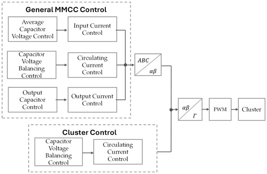
Figure 23.
Γ-coordinate capacitor voltage balancing method.
Finally, the work by Sun et al. [86] targets current-stress and efficiency bottlenecks in multi-module DABs by coupling a continuously adjustable inter-module phase shift with tunable leakage inductance. Replacing the conventional fixed phase shift and dynamically modulating the effective leakage, the strategy markedly reduces turn-off and RMS currents over a wide load range, cutting HF switching losses and magnetic volume, an especially favorable hardware-level solution for high power density, fast-transient UFCS demands. Nonetheless, the method is sensitive to coupling parameters and communication synchronization, and its robustness under complex disturbances warrants further investigation.
3.2.2. Dynamic Power Scheduling and Efficiency Optimization for Multi-Module/Multi-Port Systems
In SSTs that must coordinate several energy ports, and multiple energy terminals, Zheng et al. [87] introduce a space-vector–based partial-power-processing (PPP) control strategy. By establishing a direct power path on the low-voltage side, the scheme enables energy exchange between storage and loads without traversing the medium-voltage main chain, thereby lowering DC-link current and semiconductor stress. Compared with the conventional unified scheduling path of three-port SSTs, PPP decouples local energy through control-mode switching, which raises power density and efficiency and is well suited to UFCS scenarios that require high charge/discharge dynamics and optimized energy-flow management.
To address the issue of multi-module power scheduling in SST-based extreme fast charging stations, Choi et al. [88,89] proposed the independent module power transmission (IMPT) strategy and its improved version, individual module-power control with minimum power loss (IMCm). By designing differentiated reference voltages within a cascaded H-bridge structure, these strategies enable independent power allocation across multiple ports while optimizing power losses. It can be seen from Figure 24 that IMPT eliminates the traditional DC-DC conversion stage and directly drives the load using low-frequency reference voltages, thereby reducing intermediate energy conversion steps. IMCm further incorporates single-pulse modulation and a coordinated phase-shift mechanism to reduce high-frequency losses and enhance fundamental power transmission efficiency.

Figure 24.
Control block diagram of IMPT.
3.2.3. Grid Support and Abnormal Condition Adaptability
To enhance grid compatibility and system resilience under abnormal conditions, SST-based UFCS systems require advanced grid-support functionalities and adaptive control strategies. A comparison of representative methods is provided in Table 8.

Table 8.
Grid support control strategy comparison.
In the realm of grid-service integration, Hybrid Solid-State Transformers (HSST) leverage a combination of topology design and control optimization to deliver multidimensional power-quality regulation. Cozac et al. [90] introduce a rectifier-stage controller based on an improved single-phase p-q theory [93] and synchronous reference frame–second order generalized integrator (SRF-SOGI), which provides both harmonic suppression and reactive-power compensation, while the inverter stage employs a PPPcontrol that modulates only a fraction of the power to achieve dynamic voltage recovery, additionally exploiting the low-loss characteristics of a conventional transformer to enhance overall efficiency. Furthermore, DAB topologies adopt single-phase-shift control to enable bidirectional power scheduling, thereby improving resilience to voltage disturbances. Although this strategy has demonstrated significant power-quality improvements in a 5 kW experimental setup, its applicability to higher-power, three-phase configurations remains to be validated.
Addressing the inefficiencies and ZVS limitations of conventional DAB phase-shift control under light-load and dynamic-reactive demands, Rawat et al. propose a reduced-frequency modulation (RFM) approach that dynamically lowers the switching frequency around zero-crossings to extend the ZVS window, achieving higher light-load efficiency and reactive-power capability and reducing THD from 5.2% to 2.5% [91]. At the grid-level control layer, Ferriera Costa et al. [94] present a multilayer strategy for smart transformers (ST) that combines voltage/frequency regulation on the low-voltage side with independent reactive-power control via a medium-voltage CHB converter, augmented by online load-sensitivity identification and rapid reactive-power injection, thus enabling fine-grained load management and low-voltage ride-through while leveraging redundant hardware for enhanced fault tolerance.
Historically, Beck and Hesse’s 2007 virtual synchronous machine (VSM) control method endowed inverters with synthetic inertia comparable to synchronous generators, addressing frequency stability issues in grids with distributed generation by incorporating the rate of change in frequency (RoCoF) response to bolster support during disturbances and laying the groundwork for virtual-inertia implementations in SST systems [95]. To further tackle weak-grid frequency challenges, Wald and Carne [92] introduce an adaptive VSM control scheme that jointly considers frequency deviation and RoCoF, dynamically adjusting power setpoints to improve frequency support in low-inertia networks. By harnessing the droop characteristics of LV-side distributed energy resources (DERs) for rapid power compensation without additional hardware, it validates both stability and control agility in low-inertia environments. While offering a scalable inertia framework for SSTs under high renewable penetration, the efficiency optimization of VSM strategies in high-frequency topologies requires further investigation.
3.3. Outer Control Layer
3.3.1. System Architecture and Module-Level Communication Support
As shown in Figure 25, the work by Bipu et al. [96] addresses the need to scale charging-station clusters by proposing an outer-layer collaborative control scheme built on a distributed communication framework. Leveraging the resilient information architecture platform for the smart grid (RIAPS), a private network is established to exchange commands—such as dispatching charging-power setpoints—and monitor status parameters (for example, low-voltage bus voltage and node power) between a central controller (CCon) and multiple charging nodes (dc Nodes). Human–machine interaction and system-wide visualization are provided via a supervisory control and data acquisition (SCADA) platform. The modular, distributed (Type B) control approach permits up to eighteen single-phase modules (SPMs) to be flexibly added over fiber-optic links without reconfiguring the core logic, furnishing a robust communications backbone for large-scale resource scheduling and dynamic station expansion.
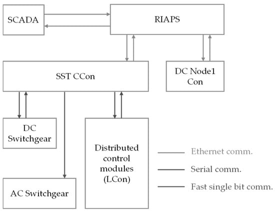
Figure 25.
Distributed communication framework.
Moreover, the same work integrates CCon’s global voltage regulation with a multi-level protection mechanism. In the event of a step increase to 50% of rated load that induces a bus-voltage sag, the system restores voltage within 250 ms. Local faults trigger µs-scale isolation via sub-module fault signals (SPM FLT) and coordinated operation of solid-state breakers (SSBs), ensuring safe operation.
To further reduce communication overhead and enhance sub-module autonomy, Topkil et al. [97] propose a hierarchical-distributed control architecture in which a global controller harmonizes grid current and aggregate DC-link voltage, as shown in Figure 26, while local controllers manage voltage tracking and modulation. By transmitting only essential control and feedback signals and sharing global objectives to enable autonomous inter-module balancing, this design minimizes inter-module data exchange while preserving real-time performance and modular expandability for high-dynamic, multi-port UFCS operation.
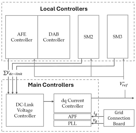
Figure 26.
Schematic of hierarchical-distributed control architecture with low-communication dependency.
Furthermore, cutting-edge research in hybrid AC/DC microgrids has proposed an even more extreme form of distributed coordination. Salman et al. [98] introduced a local-consensus algorithm to generate dynamic coordination signals, requiring the transmission of only two exponential values to key interconnection units to achieve global autonomous power balancing across sub-networks. This approach completely eliminates the need for a central computation node while reducing communication requirements to the absolute minimum. Although not yet applied directly to UFCS scenarios, its decentralized architecture and signal-minimization concept present a highly promising technical pathway for future multi-port dynamic coordination in SSTs.
3.3.2. System-Level Power Scheduling and Grid-Adaptive Control
In the system-level control framework of the work by Ferriera Costa et al. [94], the smart transformer (ST) attains multi-device coordination through both architectural innovation and global optimization. The medium-voltage DC link is reconfigured as a shared interconnection node among ST units, enabling plug-and-play integration of UFCSs and energy-storage systems within a regional DC microgrid and transcending the conventional SST limitation of purely internal isolation. Additionally, the authors introduce a grid-tailored design approach (GTDA) by reducing capacity—and thus cost—on the low-voltage side and the DC/DC stage, and reallocating those resources to double the medium-voltage stage’s capacity, GTDA achieves a twofold increase in reactive-power support without raising total system cost. Simulation studies confirm its effectiveness under complex grid conditions. Through differentiated power-stage optimization and modular expansion, GTDA offers a novel architecture that enhances grid stability amid high renewable penetration.
Extending this system-level perspective, Xu et al. [99] propose a two-stage coordinated scheduling algorithm that balances charging-power allocation against peak-load mitigation via unified dispatch of multiple SST modules or DC busses, which can be seen in Figure 27. Building on this, Tu et al. [100] proposed applying the strategy to extreme fast charging scenarios, and further suggested integrating interface topologies that support bidirectional power flow (DAB or PSFB) with local storage to improve energy coordination and disturbance rejection, thus exemplifying “topology–control co-design” for system-level scheduling.
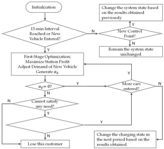
Figure 27.
Simplified flowchart of two-stage coordinated charging strategy.
Finally, Saha et al. [101] present a grid-supportive current-slope-constraint method (in Figure 28) that dynamically allocates allowable power ramp rates across vehicle ports, thereby suppressing frequency and voltage deviations during charging/discharging events. Using a layered, collaborative control structure—with the global layer coordinating front-end SST grid interaction and bus-voltage regulation in a synchronous reference frame, and local layers generating battery-state-driven reference signals subject to slope constraints—this approach achieves multi-port power balancing and modular expandability with minimal communication dependence, meeting the high-dynamics requirements of grid-interactive charging stations.
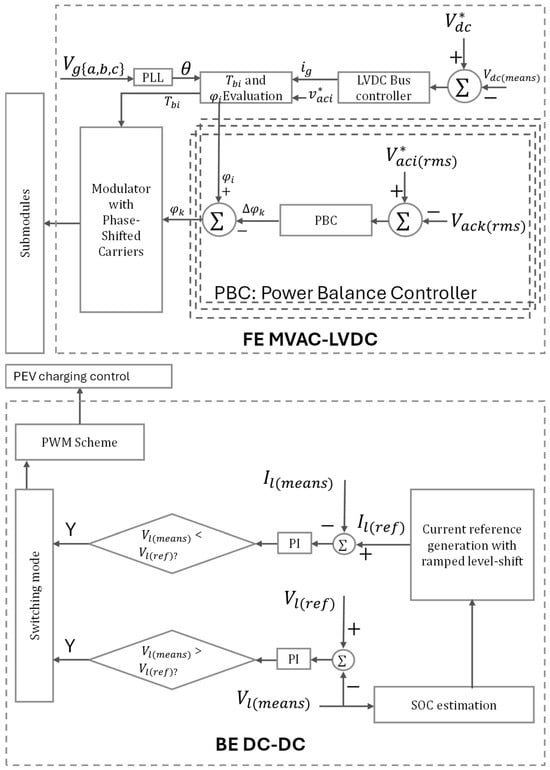
Figure 28.
Hierarchical coordinated control architecture with grid-supportive dynamic slew-rate constraint.
3.4. Control Optimization Under Complex Conditions
With the increasing demand for fast charging of EVs, studies have shown that the concentrated access of EVs significantly aggravates issues such as voltage deviation, peak load rise, harmonic injection, and neutral-line overcurrent in distribution networks, thereby increasing the sensitivity of SSTs to grid disturbances during actual operation [102,103]. In particular, the application of SSTs in UFCSs faces multiple challenges. Under weak grid conditions, voltage fluctuations and synchronization difficulties caused by low short-circuit ratio (SCR) can render traditional PLLs ineffective, necessitating enhancements such as virtual impedance and advanced PLL algorithms to improve synchronization precision [104]. Additionally, the pulsed load characteristics of UFCSs require SSTs to exhibit fast dynamic response capabilities. Sliding mode control (SMC) and virtual synchronous generator (VSG) techniques have been proposed to enhance system disturbance rejection and frequency support capabilities [105]. To address harmonics and reactive power issues induced by charging, modular multilevel topologies combined with active damping strategies help maintain grid stability, while voltage coordination among multiple SSTs must be optimized to improve power distribution efficiency. In low SCR scenarios, inverter-dominated systems face severe challenges in maintaining stability and reactive power regulation capabilities [106,107].
3.4.1. Robust Control Under Weak Grid Conditions and Parameter Uncertainty
In recent years, model predictive control (MPC) has demonstrated remarkable advantages in optimizing modular low-inertia SSTs under complex operating conditions. Zheng et al. [108] proposed a model predictive priority switching (MPPS) control strategy, which improves discrete-time modeling to effectively address the accuracy issues faced by traditional control methods in large-ripple scenarios. This approach also significantly enhances the system’s dynamic response speed. However, the study still lacks comprehensive validation in terms of grid-support functionalities and multi-module coordination. Further investigation is needed to evaluate its practical performance under complex environments such as weak grids.
Ye et al. [109] analyzed the dynamic stability of bidirectional power flow scenarios in UFCS systems using DAB converters. By constructing impedance models for both the DAB converter for SST (DAB_SST) and for distributed energy storage devices (DAB_DESD), it was revealed that DAB_SST exhibits capacitive impedance at low frequencies, while DAB_DESD under droop control behaves inductively, leading to a potential 8 Hz low-frequency resonance. To evaluate system stability, a damping-ratio-based quantitative method was proposed, and its effectiveness was confirmed through hardware-in-the-loop experiments. This impedance modeling and stability analysis approach can be extended to the dynamic interaction design of charging station clusters.
3.4.2. Dynamic Control Under Grid Faults and Overload Conditions
Under complex grid fault scenarios, the control of cascaded H-bridge SSTs must resolve the trade-off between power imbalance and modulation stability. To address active power backflow caused by inter-phase short-circuit faults, a combined strategy integrating dynamic compensation and harmonic reconstruction has been proposed [110]. This method employs adaptive zero-sequence voltage compensation (AZSVCS) to dynamically adjust the zero-sequence voltage amplitude coefficient, balancing the positive/negative sequence power components in real time based on fault depth and photovoltaic power output. Simultaneously, positive–negative-sequence harmonic zero-sequence voltage injection strategy (PNSMMHZSVIS) is used to separate the grid voltage components, extract their harmonic zero-sequence values, and reconstruct modulation signals to reduce the voltage demand on non-faulted phases. High-frequency harmonic injection further suppresses active power oscillations, significantly shrinking the overmodulation range and enhancing modulation margin under deep voltage sags and low-power conditions. A hierarchical control structure combining global optimization by a central controller and localized execution by distributed modules reduces communication delays and ensures fast DC bus voltage recovery during fault transients. Compared to harmonic current injection or centralized harmonic shaping, this voltage-component-based reconstruction approach better aligns with the modular characteristics of cascaded SSTs. It simultaneously addresses power backflow suppression and modulation stability under asymmetrical faults, providing a robust solution for high-dynamic-load applications such as pulse charging in UFCSs.
To manage overload scenarios in STs, De Carne et al. proposed a frequency-based overload control (FBOC) strategy [111]. This method dynamically adjusts grid frequency to trigger droop controllers in distributed generation (DG) units, prompting them to increase active power injection and thereby reduce the current burden on the ST. As a frequency-coordinated overload mitigation mechanism, FBOC enables dynamic power redistribution without additional hardware, offering a low-cost solution particularly suited for grids with high volatility due to high renewable energy penetration.
The aforementioned dynamic control strategies for grid fault and overload scenarios are compared in Table 9.

Table 9.
Dynamic control strategies under grid fault and overload conditions.
3.5. Topology–Control Co-Design and Synergy Analysis
Although Section 2 and Section 3, respectively, discuss the evolution of SST topologies and hierarchical control strategies, their performance potential can only be fully unlocked through coordinated topology–control design. To this end, this paper systematically summarizes in Table 10, Table 11 and Table 12 the representative “topology–control” pairings, their synergistic benefits, and validated case studies, organized around three core operational objectives—(A) high-efficiency energy conversion, (B) modularity and scalability, and (C) grid interaction and services—thereby providing clear references for the targeted design and optimization of SST-UFCSs.

Table 10.
Topology–control synergy comparison table–target: high efficiency energy conversion.

Table 11.
Topology–Control Synergy Comparison Table–Target: Modularity and Scalability.

Table 12.
Topology–control synergy comparison table–target: grid interaction and services.
4. System Performance Evaluation and Challenges
This section aims to evaluate the system-level performance of SST-based UFCSs and to discuss the key challenges that remain. Compared with conventional LFTs, SSTs leverage wide-bandgap (WBG) power devices and high-frequency resonant topologies to achieve substantial improvements in overall conversion efficiency and order-of-magnitude gains in volume and power density, as well as enhanced energy efficiency. However, they also introduce significant instantaneous power spikes, necessitating integrated energy-storage support and more advanced thermal management [112,113]. Recent assessments further indicate that current SST deployments cost at least five times more than LFTs of equivalent capacity, exhibit lower reliability, and remain incompatible with existing low-voltage protection schemes, making thermal design, cost reduction, and standards compliance critical engineering challenges [114].
4.1. Efficiency and Loss Analysis
For the final-stage DC/DC module, Jin et al. [115] employed 1 kV-class SiC MOSFETs combined with a planar integrated transformer, achieving a peak efficiency of approximately 97.7% and a power density close to 100 W/in3 at the 10 kW level. This result demonstrates that high efficiency and high density can be balanced in the lower power range through high-frequency planar magnetics and simplified air-cooling paths. Similarly, Mukherjee et al. [116] utilized 650 V GaN devices with a three-level LCL-T topology, maintaining around 98% peak efficiency and a power density of 7.3 W/cm3 across a wide output voltage range of 150–950 V. Although not yet embedded in a complete SST architecture, its excellent performance under ultra-wide voltage conditions presents feasible evidence for the future adoption of GaN-based plug-and-play power units on the low-voltage side.
When scaling up to the 20–30 kW range, 10 kV SiC MOSFETs, owing to their high voltage-blocking capability and low conduction losses, enable direct medium-voltage single-stage power conversion. Their soft-switching characteristics reduce switching losses by over 90% under high-frequency operation, supporting 99.1% and 99.0% efficiency in the AC/DC and DC/DC stages, respectively, with the overall system efficiency exceeding 98% [75,117]. At even higher power levels, such as 1 MVA, the use of 10 kV/120 An SiC half-bridge power modules combined with double-sided liquid cooling and AlN-based packaging enables system efficiency of approximately 97% at 20 kHz, while increasing power density by a factor of 2–3 compared to conventional 50/60 Hz solutions [118].
Overall, the efficiency ceiling of SST-UFCS systems exhibits a clear shift in emphasis across power levels—from device selection and magnetic integration in the low-to-medium range to combined liquid cooling and packaging optimization at high power. Future research should focus more deeply on high-temperature reliability and current-sharing strategies for high-density modules.
4.2. Reliability and Engineering Challenges
4.2.1. Thermal Management and Electro-Thermal Coordination
With the increasing power density of SSTs, thermal stress on power devices and system-level heat dissipation have become key bottlenecks limiting overall reliability. Grider et al. [118] proposed a system-level integration approach for medium-voltage SiC devices, utilizing a modular DAB architecture and low-inductance PCB layout to improve compactness. Combined with fiber-optic isolation and gate driver protection, the design enhances safety and robustness under high-voltage operation. Coupled electro-thermal modeling and optimized heat dissipation pathways provide practical guidance for engineering-oriented thermal management.
To mitigate thermal failure risks in overload conditions, Kadandani et al. [119] further propose a dynamic current limiting strategy based on junction temperature prediction. This method uses the junction temperature as the core control variable and implements real-time thermal modeling Equation (2)
and current limiting adjustment Equation (3)
to provide active thermal protection for switching devices. It effectively balances system safety and operational continuity during short-term overload events. Where is the equivalent thermal resistance and is the thermal time constant for each conduction path. where is the nominal current of the system, is the nominal operating junction temperature of the semiconductor switch, and is the temperature droop constant. This strategy exhibits strong engineering feasibility and is well-suited for handling peak load conditions in megawatt-level UFCS applications.
4.2.2. Device Aging and Lifetime-Oriented Optimization
As depicted in Figure 29, Andersen et al. [120] proposed a lifetime-aware power routing strategy that dynamically optimizes power distribution among parallel converters using junction temperature monitoring and a thermal damage accumulation model. By introducing virtual resistance control to balance current sharing and reduce hotspot temperature rise, the method enables lifetime extension of 7.5–44% under partial load conditions. Additionally, the system incorporates a single-phase inductor design to coordinate thermal stress management, supporting predictive maintenance in megawatt-scale fast charging applications. However, under unbalanced load conditions, the strategy may lead to increased current harmonics and slight efficiency degradation, necessitating further improvements in thermal design and filtering to ensure power quality and operational stability.
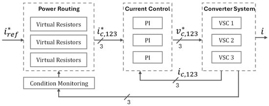
Figure 29.
Lifetime-balanced power routing control architecture.
Furthermore, Haque and Choi [121] employs a deep deterministic gradient policy (DDGP) reinforcement learning method to develop an intelligent control framework for device-aging-oriented optimization. As shown in Figure 30, the framework first defines a multi-objective optimization function for power transfer efficiency and device lifetime. An Actor network is then constructed as a dynamic phase-shift generator, mapping real-time observed states (on-state resistance, junction temperature, output voltage error) to phase-shift adjustment values. In parallel, a Critic network is designed as a dynamic reward calculator, using a segmented reward function to evaluate the long-term return of each action. During the training stage, the Actor–Critic networks perform parameter self-tuning in an offline interaction environment; the Critic network applies temporal-difference learning to minimize value-function errors, while the Actor network improves action returns via policy gradients. To balance real-time optimization and computation latency, the Actor network policy is distilled into a three-dimensional lookup table at the deployment stage. By discretizing the state space, online computation is reduced to microsecond-level memory access, effectively trading storage space for computation time. Validation on a 5 kW GaN FET SST prototype demonstrated its capability to effectively suppress temperature rise and extend device lifetime, showing strong engineering potential in dynamic power scheduling and high-frequency switching degradation management.
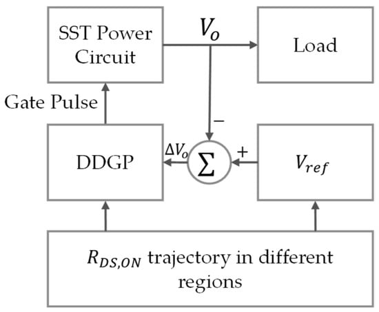
Figure 30.
Intelligent control framework using a DDGP.
4.2.3. Device-System Co-Design and Packaging Integration
Rothmund et al. [122] addressed the trade-off between efficiency and volume in medium-voltage solid-state transformers (SSTs) by proposing a co-optimization framework spanning both the device and system levels. At the device level, the method dynamically adjusts the coupling between SiC chip area and thermal resistance to balance conduction and switching losses, thereby maximizing device utilization under thermal constraints. This approach directly enhances the reliability and service life of high-voltage modules in SST-UFCS systems. At the system level, a Pareto-based multi-objective optimization was used to quantify the trade-off between efficiency and power density. This was combined with a modular multi-cell boost (MCB) topology and high-frequency soft-switching techniques to reduce the volume of passive components and lower switching losses, significantly improving system power density and dynamic responsiveness.
4.3. Commercialization Progress and Engineering Challenges
As shown in Table 13, current mainstream commercial ultra-fast charging solutions already cover a power range from 360 kW to the megawatt level and support a wide output voltage range of 150–1000 V. At present, SST-UFCSs are in a critical transition stage from laboratory validation to commercial pilot projects, with no large-scale deployment yet. Notably, pilot projects led by DG Matrix (USA) and WG Energy (China), scheduled for 2025, are expected to validate the feasibility of large-scale implementation.

Table 13.
Key parameter comparison of representative SST-UFCS commercial cases.
From the aforementioned commercialization cases and industrial deployment experience, traditional UFCS systems have revealed multiple engineering challenges during large-scale rollout.
A particularly critical issue is the redundancy dilemma caused by the fragmentation of charging standards (e.g., CCS, GB/T, and ChaoJi coexisting). To achieve full protocol compatibility, SST-based systems are often forced to prepare multiple dedicated power modules at the hardware level or adopt overly complex wide-range circuit designs. Current industrial solutions generally rely on multi-tap medium-frequency transformers. In contrast, SST-UFCSs require variable turn ratio high-frequency topologies (e.g., variable-ratio LLC) combined with SiC/GaN devices to reduce switching losses. This leads to exponential increases in cost, volume, and thermal management complexity. On the control side, heterogeneous communication stacks (e.g., coexistence of PLC and PWM) and dynamic processes (e.g., V2G scheduling) undermine the “plug-and-play” nature of the software layer, forcing the central controller to preload all potential protocols. Any update in standards may trigger a global firmware update, significantly increasing system maintenance complexity and downtime risks.
To address these challenges, SST-UFCS design can be optimized in three directions. First, inspired by cloud-computing concepts, a protocol-agnostic “universal power pool” can be constructed to handle wide-range DC output, while hot-swappable “software-defined interface modules” are deployed at the terminal for protocol conversion and connector management. This approach decouples the core power hardware from rapidly evolving interface standards, enabling flexible upgrades and cost control. Second, the establishment of an “interface abstraction layer” and an open reference ecosystem should be promoted. Industry alliances could define hardware-independent communication abstraction layers (e.g., based on Open Platform Communications Unified Architecture or specific middleware) and release open-source reference designs for mechanical, electrical, and thermal integration (similar to the Open Compute Project model), thereby reducing redundant development costs for downstream manufacturers and facilitating cross-brand compatibility. Finally, resolving the fragmentation dilemma requires a combination of technology, policy, and business models. Regulatory bodies should promote test mutual recognition to reduce market entry barriers, while operators can adopt “standard bundles”, flexibly activating different charging protocol services on a pay-as-you-go basis.
In terms of protection, high-voltage insulation and short-circuit protection are essential for high-voltage-level deployment. For operating voltages up to 1500 V DC and 10 kV AC, high–thermal-conductivity, low-loss silicone combined with vacuum pressure impregnation can be used, along with graded electric field control between medium-voltage (MV) and low-voltage (LV) windings to enhance insulation performance and structural compactness. For short-circuit protection, measures such as core grounding, ultra-fast gate protection circuits, and low-inductance busbar design can be integrated to achieve millisecond-level fault current interruption [129,130,131,132].
4.4. Future Trends and Research Directions
To enable solid-state transformer (SST)-based ultra-fast charging stations (UFCSs) to play a central role in large-scale deployment, future research should advance along two main directions: multi-dimensional co-optimization and long-term frontier exploration. In the short term, efforts should focus on the most urgent industrial needs—cost reduction, efficiency improvement, and standardization; in the medium term, the priority should shift toward reliability enhancement; in the long term, attention should be given to intelligent optimization and adaptation to extreme operating scenarios.
In terms of short-term cost reduction and efficiency improvement, future development will continue toward high-frequency soft switching, modular integration, and multi-port integration to improve energy conversion efficiency and power density. In particular, the high-frequency soft-switching and structural integration trends of resonant topologies, the structural simplification and multi-port integration of DAB topologies, and the increasing maturity of hybrid topologies in industrial-scale UFCS applications all provide clear technical pathways for subsequent topology innovation. For standardization, it is necessary to establish a standardized performance index system, specifying thresholds and testing methods for key indicators such as voltage regulation accuracy, total harmonic distortion (THD), and fault ride-through capability, in order to support technology selection and grid compatibility certification [133].
For medium-term technological breakthroughs, control strategies must address the higher demands posed by complex operating conditions in UFCS applications—such as pulsed load impacts, multi-port energy interactions (e.g., V2G), grid faults, and renewable energy fluctuations. Large-scale EV loads can cause voltage deviations, harmonic pollution, and power flow disturbances, necessitating the development of more robust grid-interactive control and power-quality assurance mechanisms [11]. Future work should focus on advanced control strategies such as model predictive control (MPC), refined management of modular control and voltage coordination, and enhanced frequency/voltage stability under weak-grid and disturbed-grid conditions. At the device level, further application of wide-bandgap semiconductors (e.g., SiC, GaN) will help reduce module size and thermal stress. At the system level, advances in thermal management, electro-thermal co-design, lifetime-aware control strategies, and coordinated chip- and system-level design will significantly enhance operational reliability and service life.
In the long-term frontier exploration, a comprehensive evaluation model should be established to include lifecycle cost, dynamic efficiency, and environmental impact, enabling a quantitative assessment of trade-offs between economic feasibility and technical advantages [133]. Moreover, as artificial intelligence and power electronics become increasingly integrated, machine-learning-assisted multi-objective optimization is emerging. For instance, the approach proposed by Jaydeep Saha et al. [134] employs local parameter optimization, optimal-sample training, and ML-based global prediction to jointly optimize SST efficiency and power density. This intelligent optimization workflow not only accelerates hardware design but also offers new perspectives for achieving high performance and modular scalability in the future.
5. Conclusions
This paper provides a comprehensive and systematic review of the latest advancements in SSTs for UFCSs, focusing on the evolution of topological structures, control strategies, and grid interaction characteristics. It offers an in-depth analysis of system performance and key technical challenges, thereby outlining the core value and practical potential of SSTs in the ultra-fast charging domain.
At present, SSTs have emerged as a cornerstone technology for next-generation UFCS infrastructure, owing to their significant advantages in power density enhancement, high-frequency soft switching, and bidirectional energy exchange capabilities. However, several barriers remain—such as increased engineering complexity, high system costs, communication standard adaptation, and thermal management difficulties—which must be addressed to facilitate the transition from conceptual validation to large-scale deployment.
This review shows that SST technology has already established its pivotal role in modern energy systems. Future research should continue to emphasize the co-optimization of technical performance and economic viability, accelerating the translation from laboratory prototypes to practical engineering applications. Ultimately, this will support the broader, more stable, and cost-effective rollout of ultra-fast charging infrastructure.
Author Contributions
H.X. managed the conceptualization, methodology, investigation, and writing of the original draft. K.P. contributed to the methods and reviewed and edited the manuscript. J.K. reviewed and edited the manuscript. Both K.P. and J.K. supervised the PhD student H.X. All authors have read and agreed to the published version of the manuscript.
Funding
This research received no external funding.
Data Availability Statement
The data are contained within the article.
Conflicts of Interest
The authors declare that they have no conflicts of interest.
References
- U.S. Department of Energy. Enabling Fast Charging Infrastructure for EVs; U.S. Department of Energy: Washington, DC, USA, 2017.
- Rivera, S.; Goetz, S.M.; Kouro, S.; Lehn, P.W.; Pathmanathan, M.; Bauer, P.; Mastromauro, R.A. Charging Infrastructure and Grid Integration for Electromobility. Proc. IEEE 2023, 111, 371–396. [Google Scholar] [CrossRef]
- IEC 61851-23:2023; Electric Vehicle Conductive Charging System-Part 23: DC Electric Vehicle Supply Equipment. International Electrochemical Commission: Geneva, Switzerland, 2023.
- GB/T 20234.3-2023; Electric Vehicle Conductive Charging System. Part 23, DC Electric Vehicle Supply Equipment. Standardization Administration of China International Electrotechnical Commission: Beijing, China, 2023.
- Mishra, D.K.; Ghadi, M.J.; Li, L.; Hossain, J.; Zhang, J.; Ray, P.K.; Mohanty, A. A Review on Solid-State Transformer: A Breakthrough Technology for Future Smart Distribution Grids. Int. J. Electr. Power Energy Syst. 2021, 133, 107255. [Google Scholar] [CrossRef]
- Ahmed, S.; Bloom, I.; Jansen, A.N.; Tanim, T.; Dufek, E.J.; Pesaran, A.; Burnham, A.; Carlson, R.B.; Dias, F.; Hardy, K.; et al. Enabling Fast Charging—A Battery Technology Gap Assessment. J. Power Sources 2017, 367, 250–262. [Google Scholar] [CrossRef]
- Wang, L.; Qin, Z.; Slangen, T.; Bauer, P.; Van Wijk, T. Grid Impact of Electric Vehicle Fast Charging Stations: Trends, Standards, Issues and Mitigation Measures—An Overview. IEEE Open J. Power Electron. 2021, 2, 56–74. [Google Scholar] [CrossRef]
- Tahir, Y.; Khan, I.; Rahman, S.; Khan, M.A.; Nadeem, M.F.; Iqbal, A.; Iqbal, A.; Xu, Y.; Xu, Y.; Rafi, M.; et al. A State-of-the-Art Review on Topologies and Control Techniques of Solid-State Transformers for Electric Vehicle Extreme Fast Charging. IET Power Electron. 2021, 14, 1560–1576. [Google Scholar] [CrossRef]
- Ahmad, A.; Qin, Z.; Wijekoon, T.; Bauer, P. An Overview on Medium Voltage Grid Integration of Ultra-Fast Charging Stations: Current Status and Future Trends. IEEE Open J. Ind. Electron. Soc. 2022, 3, 420–447. [Google Scholar] [CrossRef]
- Hannan, M.A.; Ker, P.J.; Lipu, M.S.H.; Choi, Z.H.; Rahman, S.A.; Muttaqi, K.M.; Blaabjerg, F. State of the Art of Solid-State Transformers: Advanced Topologies, Implementation Issues, Recent Progress and Improvements. IEEE Access 2020, 8, 19113–19132. [Google Scholar] [CrossRef]
- Acharige, S.S.G.; Haque, E.; Arif, M.T.; Hosseinzadeh, N.; Hasan, K.N.; Oo, A.M.T. Review of Electric Vehicle Charging Technologies, Standards, Architectures, and Converter Configurations. IEEE Access 2023, 11, 41218–41255. [Google Scholar] [CrossRef]
- Khalid, M.R.; Khan, I.A.; Hameed, S.; Asghar, M.S.J.; Ro, J. A Comprehensive Review on Structural Topologies, Power Levels, Energy Storage Systems, and Standards for Electric Vehicle Charging Stations and Their Impacts on Grid. IEEE Access 2021, 9, 128069–128094. [Google Scholar] [CrossRef]
- Valedsaravi, S.; El Aroudi, A.; Martínez-Salamero, L. Review of Solid-State Transformer Applications on Electric Vehicle DC Ultra-Fast Charging Station. Energies 2022, 15, 5602. [Google Scholar] [CrossRef]
- Safayatullah, M.; Elrais, M.T.; Ghosh, S.; Rezaii, R.; Batarseh, I. A Comprehensive Review of Power Converter Topologies and Control Methods for Electric Vehicle Fast Charging Applications. IEEE Access 2022, 10, 40753–40793. [Google Scholar] [CrossRef]
- Kilicoglu, H.; Tricoli, P. Technical Review and Survey of Future Trends of Power Converters for Fast-Charging Stations of Electric Vehicles. Energies 2023, 16, 5204. [Google Scholar] [CrossRef]
- Chon, S.; Bhardwaj, M.; Nene, H. Maximizing Power for Level 3 EV Charging Stations; Texas Instruments: Dallas, TX, USA, 2018. [Google Scholar]
- Kang, T.; Kim, C.; Suh, Y.; Park, H.; Kang, B.; Kim, D. A Design and Control of Bi-Directional Non-Isolated DC-DC Converter for Rapid Electric Vehicle Charging System. In Proceedings of the 2012 Twenty-Seventh Annual IEEE Applied Power Electronics Conference and Exposition (APEC), Orlando, FL, USA, 5–9 February 2012; IEEE: Piscataway, NJ, USA, 2012; pp. 14–21. [Google Scholar]
- Zhou, K.; Wu, Y.; Wu, X.; Sun, Y.; Teng, D.; Liu, Y. Research and Development Review of Power Converter Topologies and Control Technology for Electric Vehicle Fast-Charging Systems. Electronics 2023, 12, 1581. [Google Scholar] [CrossRef]
- Soeiro, T.B.; Friedli, T.; Kolar, J.W. Swiss Rectifier—A Novel Three-Phase Buck-Type PFC Topology for Electric Vehicle Battery Charging. In Proceedings of the 2012 Twenty-Seventh Annual IEEE Applied Power Electronics Conference and Exposition (APEC), Orlando, FL, USA, 5–9 February 2012; IEEE: Piscataway, NJ, USA, 2012; pp. 2617–2624. [Google Scholar]
- Zhu, C. High-Efficiency, Medium-Voltage-Input, Solid-State-Transformer-Based 400-kW/1000V/400A Extreme Fast Charger for Electric Vehicles; Report by Delta Electronics; Delta Electronics: Santa Clara, CA, USA, 2023. [Google Scholar] [CrossRef]
- Srdic, S.; Liang, X.; Zhang, C.; Yu, W.; Lukic, S. A SiC-Based High-Performance Medium-Voltage Fast Charger for Plug-in Electric Vehicles. In Proceedings of the 2016 IEEE Energy Conversion Congress and Exposition (ECCE), Milwaukee, WI, USA, 18–22 September 2016; IEEE: Piscataway, NJ, USA, 2016; pp. 1–6. [Google Scholar]
- Lim, C.-Y.; Jeong, Y.; Moon, G.-W. Phase-Shifted Full-Bridge DC–DC Converter with High Efficiency and High Power Density Using Center-Tapped Clamp Circuit for Battery Charging in Electric Vehicles. IEEE Trans. Power Electron. 2019, 34, 10945–10959. [Google Scholar] [CrossRef]
- Jang, Y.; Jovanović, M.M. The TAIPEI Rectifier—A New Three-Phase Two-Switch ZVS PFC DCM Boost Rectifier. IEEE Trans. Power Electron. 2013, 28, 686–694. [Google Scholar] [CrossRef]
- Zhang, C.; Wang, R.; Shen, Z.; Sadilek, T.; Anurag, A.; Barbosa, P. A Single-Stage Three-Phase Isolated AC-DC Converter for Medium Voltage Solid State Transformer Applications. In Proceedings of the 2023 IEEE Applied Power Electronics Conference and Exposition (APEC), Orlando, FL, USA, 19 March 2023; IEEE: Piscataway, NJ, USA, 2023; pp. 1503–1509. [Google Scholar]
- Xu, W.; Rajendran, S.; Guo, Z.; Vctrivelan, A.; Huang, A.Q. 7.2kV/100kVA Solid State Transformer Based on Half Bridge LLC Resonant Converter and 15kV SiC AC Switch. In Proceedings of the 2023 IEEE Applied Power Electronics Conference and Exposition (APEC), Orlando, FL, USA, 19 March 2023; IEEE: Piscataway, NJ, USA, 2023; pp. 1516–1522. [Google Scholar]
- Shu, L.; Chen, W.; Liu, R.; Shi, M. Analysis and Design of Bidirectional Three-Phase Triple-Voltage LLC (T2 -LLC) Resonant Converter for Solid-State Transformer Application. In Proceedings of the 2021 IEEE Sustainable Power and Energy Conference (iSPEC), Nanjing, China, 23 December 2021; IEEE: Piscataway, NJ, USA, 2021; pp. 3305–3310. [Google Scholar]
- Zhao, B.; Song, Q.; Liu, W.; Sun, Y. Overview of Dual-Active-Bridge Isolated Bidirectional DC–DC Converter for High-Frequency-Link Power-Conversion System. IEEE Trans. Power Electron. 2014, 29, 4091–4106. [Google Scholar] [CrossRef]
- Patil, N.S.; Shukla, A. Review and Comparison of MV Grid-Connected Extreme Fast Charging Converters for Electric Vehicles. In Proceedings of the 2021 National Power Electronics Conference (NPEC), Bhubaneswar, India, 15 December 2021; IEEE: Piscataway, NJ, USA, 2021; pp. 1–6. [Google Scholar]
- Su, M.; Huang, J.; Wang, H.; Jiang, L.; Chen, X. Direct AC–AC Solid-State Transformer Based on Hybrid DAB. IEEE J. Emerg. Sel. Top. Power Electron. 2024, 12, 1385–1394. [Google Scholar] [CrossRef]
- Dao, N.D.; Nguyen, H.V.; Lee, D.-C. Semi-Modular Solid-State Transformers with Reduced Count of Components Based on Single-Stage AC/DC Converters. IEEE Trans. Power Electron. 2022, 37, 8177–8189. [Google Scholar] [CrossRef]
- De Seram, R.; Lulbadda, K.T.; Sidhu, T.; Williamson, S.S. A Quad-Active Bridge (QAB)-Based Solid-State Transformer for Fast Charging of Light/Medium and Heavy Electric Vehicles. In Proceedings of the 2024 IEEE International Conference on Industrial Technology (ICIT), Bristol, UK, 25 March 2024; IEEE: Piscataway, NJ, USA, 2024; pp. 1–6. [Google Scholar]
- Cao, H.; Du, L.; Guo, F.; Ma, Z.; Zhao, Y. A Triple Active Bridge (TAB) Based Solid-State Transformer (SST) for DC Fast Charging Systems: Architecture and Control Strategy. In Proceedings of the 2023 IEEE Energy Conversion Congress and Exposition (ECCE), Nashville, TN, USA, 29 October 2023; IEEE: Piscataway, NJ, USA, 2023; pp. 855–860. [Google Scholar]
- Gabriel, M.T.; Mansour, D.-E.A.; Shoyama, M.; Abdelkader, S.M. A Triple-Active Bridge Based Solid State Transformer Fast Charging Station Topology for Electric Vehicles. In Proceedings of the 2024 IEEE International Conference on Environment and Electrical Engineering and 2024 IEEE Industrial and Commercial Power Systems Europe (EEEIC/I&CPS Europe), Rome, Italy, 17 June 2024; IEEE: Piscataway, NJ, USA, 2024; pp. 1–6. [Google Scholar]
- Lai, J.-S.; Lai, W.-H.; Moon, S.-R.; Zhang, L.; Maitra, A. A 15-kV Class Intelligent Universal Transformer for Utility Applications. In Proceedings of the 2016 IEEE Applied Power Electronics Conference and Exposition (APEC), Long Beach, CA, USA, 20–24 March 2016; IEEE: Piscataway, NJ, USA, 2016; pp. 1974–1981. [Google Scholar]
- Liang, X.; Srdic, S.; Won, J.; Aponte, E.; Booth, K.; Lukic, S. A 12.47 kV Medium Voltage Input 350 kW EV Fast Charger Using 10 kV SiC MOSFET. In Proceedings of the 2019 IEEE Applied Power Electronics Conference and Exposition (APEC), Anaheim, CA, USA, 17–21 March 2019; IEEE: Piscataway, NJ, USA, 2019; pp. 581–587. [Google Scholar]
- Lee, M.; Yeh, C.-S.; Yu, O.; Kim, J.-W.; Choe, J.-M.; Lai, J.-S. Modeling and Control of Three-Level Boost Rectifier Based Medium-Voltage Solid-State Transformer for DC Fast Charger Application. IEEE Trans. Transp. Electrif. 2019, 5, 890–902. [Google Scholar] [CrossRef]
- Nair, A.C.; Fernandes, B.G. Solid-State Transformer Based Fast Charging Station for Various Categories of Electric Vehicles with Batteries of Vastly Different Ratings. IEEE Trans. Ind. Electron. 2021, 68, 10400–10411. [Google Scholar] [CrossRef]
- Suarez, C.; Martinez, W. Fast and Ultra-Fast Charging for Battery Electric Vehicles—A Review. In Proceedings of the 2019 IEEE Energy Conversion Congress and Exposition (ECCE), Baltimore, MD, USA, 29 September–3 October 2019; IEEE: Piscataway, NJ, USA, 2019; pp. 569–575. [Google Scholar]
- Allebrod, S.; Hamerski, R.; Marquardt, R. New Transformerless, Scalable Modular Multilevel Converters for HVDC-Transmission. In Proceedings of the 2008 IEEE Power Electronics Specialists Conference, Rhodes, Greece, 15–19 June 2008; IEEE: Piscataway, NJ, USA, 2008; pp. 174–179. [Google Scholar]
- Makoschitz, M. Unidirectional Medium Voltage Rectifier Utilizing Sinusoidal Input Currents. Electron. Lett. 2022, 58, 474–476. [Google Scholar] [CrossRef]
- Makoschitz, M.; Hartmann, M.; Ertl, H. Control Concepts for Hybrid Rectifiers Utilizing a Flying Converter Cell Active Current Injection Unit. IEEE Trans. Power Electron. 2017, 32, 2584–2595. [Google Scholar] [CrossRef]
- Andrioli, G.; Calligaro, S.; Petrella, R.; Kolar, J.W.; Huber, J. Analysis and Comparative Evaluation of a Modularized Bridge Rectifier MVAC-LVDC Solid-State Transformer. In Proceedings of the 2024 IEEE 10th International Power Electronics and Motion Control Conference (IPEMC2024-ECCE Asia), Chengdu, China, 17 May 2024; IEEE: Piscataway, NJ, USA, 2024; pp. 2722–2729. [Google Scholar]
- Vasiladiotis, M.; Rufer, A.; Beguin, A. Modular Converter Architecture for Medium Voltage Ultra Fast EV Charging Stations: Global System Considerations. In Proceedings of the 2012 IEEE International Electric Vehicle Conference, Greenville, SC, USA, 4–8 March 2012; IEEE: Piscataway, NJ, USA, 2012; pp. 1–7. [Google Scholar]
- Ma, Z.; Cao, H.; Zhao, Y. Modular Design of Solid-State Transformer with High Flexibility. In Proceedings of the 2024 IEEE Energy Conversion Congress and Exposition (ECCE), Phoenix, AZ, USA, 20 October 2024; IEEE: Piscataway, NJ, USA, 2024; pp. 149–155. [Google Scholar]
- Vasiladiotis, M.; Rufer, A. A Modular Multiport Power Electronic Transformer with Integrated Split Battery Energy Storage for Versatile Ultrafast EV Charging Stations. IEEE Trans. Ind. Electron. 2015, 62, 3213–3222. [Google Scholar] [CrossRef]
- Barresi, M.; Ferri, E.; Piegari, L. Solid-State Transformer for EV Ultra-Fast Charging Stations with Series-Connected Dc-Buses for Multiple Charging Voltages. In Proceedings of the 2024 IEEE Transportation Electrification Conference and Expo (ITEC), Chicago, IL, USA, 19 June 2024; IEEE: Piscataway, NJ, USA, 2024; pp. 1–7. [Google Scholar]
- Saha, J.; Kumar, N.; Panda, S.K. A Futuristic Silicon-Carbide (SiC)-Based Electric-Vehicle Fast Charging/Discharging (FC/dC) Station. IEEE J. Emerg. Sel. Top. Power Electron. 2023, 11, 2904–2917. [Google Scholar] [CrossRef]
- Costa, L.F.; Buticchi, G.; Liserre, M. Quad-Active-Bridge DC–DC Converter as Cross-Link for Medium-Voltage Modular Inverters. IEEE Trans. Ind. Appl. 2017, 53, 1243–1253. [Google Scholar] [CrossRef]
- Hussain, M.N.; Furukawa, K.; Mabuchi, Y.; Choudhury, A. A Solid-State Transformer with an AC Link for Multi-Port Fast Charging of Electric Vehicles. In Proceedings of the 2023 IEEE Transportation Electrification Conference & Expo (ITEC), Detroit, MI, USA, 21 June 2023; IEEE: Piscataway, NJ, USA, 2023; pp. 1–6. [Google Scholar]
- Nami, A.; Liang, J.; Dijkhuizen, F.; Demetriades, G.D. Modular Multilevel Converters for HVDC Applications: Review on Converter Cells and Functionalities. IEEE Trans. Power Electron. 2015, 30, 18–36. [Google Scholar] [CrossRef]
- Ronanki, D.; Williamson, S.S. Modular Multilevel Converters for Transportation Electrification: Challenges and Opportunities. IEEE Trans. Transp. Electrif. 2018, 4, 399–407. [Google Scholar] [CrossRef]
- Raju, M.N.; Sreedevi, J.; Mandi, R.P.; Meera, K.S. Modular Multilevel Converters Technology: A Comprehensive Study on Its Topologies, Modelling, Control and Applications. IET Power Electron. 2019, 12, 149–169. [Google Scholar] [CrossRef]
- Priya, M.; Ponnambalam, P.; Muralikumar, K. Modular-multilevel Converter Topologies and Applications—A Review. IET Power Electron. 2019, 12, 170–183. [Google Scholar] [CrossRef]
- Lan, X.; Lehn, P. A Single-Phase MMC-Based Solid-State Transformer Suitable for EV Charging. In Proceedings of the 2024 IEEE Energy Conversion Congress and Exposition (ECCE), Phoenix, AZ, USA, 20 October 2024; IEEE: Piscataway, NJ, USA, 2024; pp. 3304–3311. [Google Scholar]
- Jianqiao, Z.; Jianwen, Z.; Xu, C.; Jiacheng, W.; Jiajie, Z. Family of Modular Multilevel Converter (MMC) Based Solid State Transformer (SST) Topologies for Hybrid AC/DC Distribution Grid Applications. In Proceedings of the 2018 IEEE International Power Electronics and Application Conference and Exposition (PEAC), Shenzhen, China, 4–7 November 2018; IEEE: Piscataway, NJ, USA, 2018; pp. 1–5. [Google Scholar]
- Himmelmann, P.; Hiller, M. Solid-state Transformer Based on Modular Multilevel Converters. J. Eng. 2019, 2019, 4490–4494. [Google Scholar] [CrossRef]
- Zheng, G.; Chen, Y.; Kang, Y. A Modular Multilevel Converter (MMC) Based Solid-State Transformer (SST) Topology with Simplified Energy Conversion Process and Magnetic Integration. IEEE Trans. Ind. Electron. 2021, 68, 7725–7735. [Google Scholar] [CrossRef]
- Teng, J.; Sun, X.; Pan, Y.; Liu, X.; Zhang, Y.; Zhao, W.; Li, X. An Inductive-Filtering Strategy of Submodule Ripple-Power in Triple-Port MMC-Based SST Applied to Hybrid Medium and Low Voltage AC/DC Interface. IEEE Trans. Power Electron. 2022, 37, 8015–8032. [Google Scholar] [CrossRef]
- Li, L.; Li, K.-J.; Sun, K.; Liu, Z. A Three-Port PSFB/DAB-MMC PET with Inertia Enhancement Under LVDC Disturbance. IEEE Trans. Ind. Appl. 2023, 59, 300–311. [Google Scholar] [CrossRef]
- Pool-Mazun, E.I.; Sandoval, J.J.; Enjeti, P.N.; Pitel, I.J. An Integrated Solid-State Transformer with High-Frequency Isolation for EV Fast-Charging Applications. IEEE J. Emerg. Sel. Top. Ind. Electron. 2020, 1, 46–56. [Google Scholar] [CrossRef]
- Zheng, L.; Kandula, R.P.; Divan, D. Soft-Switching Solid-State Transformer with Reduced Conduction Loss. IEEE Trans. Power Electron. 2021, 36, 5236–5249. [Google Scholar] [CrossRef]
- Zheng, L.; Han, X.; An, Z.; Kandula, R.P.; Kandasamy, K.; Saeedifard, M.; Divan, D. SiC-Based 5-kV Universal Modular Soft-Switching Solid-State Transformer (M-S4T) for Medium-Voltage DC Microgrids and Distribution Grids. IEEE Trans. Power Electron. 2021, 36, 11326–11343. [Google Scholar] [CrossRef]
- Hartmann, M.; Fehringer, R. Active Three-Phase Rectifier System Using a “Flying” Converter Cell. In Proceedings of the 2012 IEEE International Energy Conference and Exhibition (ENERGYCON), Florence, Italy, 9–12 September 2012; IEEE: Piscataway, NJ, USA, 2012; pp. 82–89. [Google Scholar]
- Iyer, V.M.; Gulur, S.; Gohil, G.; Bhattacharya, S. An Approach Towards Extreme Fast Charging Station Power Delivery for Electric Vehicles with Partial Power Processing. IEEE Trans. Ind. Electron. 2020, 67, 8076–8087. [Google Scholar] [CrossRef]
- Liserre, M.; Buticchi, G.; Andresen, M.; De Carne, G.; Costa, L.F.; Zou, Z.-X. The Smart Transformer: Impact on the Electric Grid and Technology Challenges. IEEE Ind. Electron. Mag. 2016, 10, 46–58. [Google Scholar] [CrossRef]
- De Carne, G.; Buticchi, G.; Liserre, M.; Yoon, C.; Blaabjerg, F. Voltage and Current Balancing in Low and Medium Voltage Grid by Means of Smart Transformer. In Proceedings of the 2015 IEEE Power & Energy Society General Meeting, Denver, CO, USA, 26–30 July 2015; pp. 1–5. [Google Scholar] [CrossRef]
- Zou, Z.-X.; De Carne, G.; Buticchi, G.; Liserre, M. Smart Transformer-Fed Variable Frequency Distribution Grid. IEEE Trans. Ind. Electron. 2018, 65, 749–759. [Google Scholar] [CrossRef]
- Liserre, M.; Perez, M.A.; Langwasser, M.; Rojas, C.A.; Zhou, Z. Unlocking the Hidden Capacity of the Electrical Grid Through Smart Transformer and Smart Transmission. Proc. IEEE 2023, 111, 421–437. [Google Scholar] [CrossRef]
- She, X.; Huang, A.Q.; Burgos, R. Review of Solid-State Transformer Technologies and Their Application in Power Distribution Systems. IEEE J. Emerg. Sel. Top. Power Electron. 2013, 1, 186–198. [Google Scholar] [CrossRef]
- Agarwal, R.; Li, H.; Guo, Z.; Cheetham, P. The Effects of PWM with High Dv/Dt on Partial Discharge and Lifetime of Medium-Frequency Transformer for Medium-Voltage (MV) Solid State Transformer Applications. IEEE Trans. Ind. Electron. 2023, 70, 3857–3866. [Google Scholar] [CrossRef]
- Saha, J.; Gorla, N.B.Y.; Subramaniam, A.; Panda, S.K. Analysis of Modulation and Optimal Design Methodology for Half-Bridge Matrix-Based Dual-Active-Bridge (MB-DAB) AC–DC Converter. IEEE J. Emerg. Sel. Top. Power Electron. 2022, 10, 881–894. [Google Scholar] [CrossRef]
- Saha, J.; Yadav Gorla, N.B.; Panda, S.K. Analytical Expression-Based Modulation for Soft-Switched Matrix-Based Dual-Active-Bridge (S2MB-DAB) Single-Phase AC-DC Converter. IEEE J. Emerg. Sel. Top. Power Electron. 2022, 10, 6511–6522. [Google Scholar] [CrossRef]
- Jean-Pierre, G.; Beheshtaein, S.; Altin, N.; Nasiri, A. Control and Loss Analysis of a Solid State Transformer Based DC Extreme Fast Charger. In Proceedings of the 2021 IEEE Transportation Electrification Conference & Expo (ITEC), Chicago, IL, USA, 21 June 2021; IEEE: Piscataway, NJ, USA, 2021; pp. 9–14. [Google Scholar]
- Jean-Pierre, G.; Altin, N.; El Shafei, A.; Nasiri, A. Efficiency Optimization of Dual Active Bridge DC– DC Converter with Triple Phase-Shift Control. In Proceedings of the 2020 IEEE Energy Conversion Congress and Exposition (ECCE), Detroit, MI, USA, 11 October 2020; IEEE: Piscataway, NJ, USA, 2020; pp. 1217–1222. [Google Scholar]
- Rothmund, D.; Guillod, T.; Bortis, D.; Kolar, J.W. 99.1% Efficient 10 kV SiC-Based Medium-Voltage ZVS Bidirectional Single-Phase PFC AC/DC Stage. IEEE J. Emerg. Sel. Top. Power Electron. 2019, 7, 779–797. [Google Scholar] [CrossRef]
- Andrioli, G.; Calligaro, S.; Huber, J.; Kolar, J.W.; Petrella, R. Advanced Control of Modularized Bridge Rectifier Solid-State Transformers in MVAC-LVDC Applications. In Proceedings of the 2024 IEEE Energy Conversion Congress and Exposition (ECCE), Phoenix, AZ, USA, 20 October 2024; IEEE: Piscataway, NJ, USA, 2024; pp. 3259–3266. [Google Scholar]
- Lahooti Eshkevari, A.; Mosallanejad, A.; Sepasian, M. In-depth Study of the Application of Solid-state Transformer in Design of High-power Electric Vehicle Charging Stations. IET Electr. Syst. Transp. 2020, 10, 310–319. [Google Scholar] [CrossRef]
- Zhou, J.; Zhang, J.; Wang, J.; Zang, J.; Shi, G.; Feng, X.; Cai, X. Design and Control of Power Fluctuation Delivery for Cell Capacitance Optimization in Multiport Modular Solid-State Transformers. IEEE Trans. Power Electron. 2021, 36, 1412–1427. [Google Scholar] [CrossRef]
- Zheng, L.; Kandula, R.P.; Divan, D. Predictive Direct DC-Link Control for 7.2 kV Three-Port Low-Inertia Solid-State Transformer with Active Power Decoupling. IEEE Trans. Power Electron. 2022, 37, 11673–11685. [Google Scholar] [CrossRef]
- Cao, H.; Wang, H.; Darvish, P.; Du, L.; Wang, Z.; Yang, Y.; Ma, Z.; Zhao, Y. Double Line Frequency Voltage Ripple Reduction Control Strategy for Dual-Active-Bridge in DC/AC System. In Proceedings of the 2024 IEEE Energy Conversion Congress and Exposition (ECCE), Phoenix, AZ, USA, 20 October 2024; IEEE: Piscataway, NJ, USA, 2024; pp. 269–275. [Google Scholar]
- Saha, J.; Gorla, N.B.Y.; Panda, S.K. Implementation of Power Balance Control Scheme for a Cascaded Matrix-Based Dual-Active-Bridge (CMB-DAB) MVAC-LVDC Converter. IEEE Trans. Ind. Appl. 2022, 58, 388–399. [Google Scholar] [CrossRef]
- Saha, J.; Sundararajan, P.; Panda, S.K. Evaluation of Closed-Loop Control Techniques for Single-Stage MVAC-LVDC Solid-State-Transformers in Compact EV Ultra-Fast Charging Stations. In Proceedings of the 2024 IEEE 10th International Power Electronics and Motion Control Conference (IPEMC2024-ECCE Asia), Chengdu, China, 17 May 2024; IEEE: Piscataway, NJ, USA, 2024; pp. 182–187. [Google Scholar]
- Saha, J.; Gorla, N.B.Y.; Panda, S.K. Closed-Form Solution for Multiobjective Optimal Analytical Balance Control for a Single-Stage Isolated MVAC-LVDC Converter in an Electric-Vehicle Ultra-Fast Charging Station. IEEE Trans. Transp. Electrif. 2024, 10, 9055–9070. [Google Scholar] [CrossRef]
- Shi, H.; Wen, H.; Chen, J.; Hu, Y.; Jiang, L.; Chen, G.; Ma, J. Minimum-Backflow-Power Scheme of DAB-Based Solid-State Transformer with Extended-Phase-Shift Control. IEEE Trans. Ind. Appl. 2018, 54, 3483–3496. [Google Scholar] [CrossRef]
- Verdugo, D.; Lillo, J.; Rojas, F.; Azharuddin, M.; Pereda, J. Capacitor Balance Control of a Modular Multilevel Converter Based on Parallel Connected Branches for a MVAC/LVDC Solid State Transformer. In Proceedings of the 2021 IEEE 22nd Workshop on Control and Modelling of Power Electronics (COMPEL), Cartagena, Colombia, 2 November 2021; IEEE: Piscataway, NJ, USA, 2021; pp. 1–7. [Google Scholar]
- Sun, K.; Su, M.; Xu, G.; Chen, X.; Xiong, W. Modulated Coupled Inductor-Based IPOP-DAB Converter with Optimized Modulation Trajectory Considering the Phase-Shift Angle Between Submodules for SST Applications. IEEE J. Emerg. Sel. Top. Power Electron. 2023, 11, 6112–6123. [Google Scholar] [CrossRef]
- Zheng, L.; Kandula, R.P.; Divan, D. Multiport Power Management Method with Partial Power Processing in a MV Solid-State Transformer for PV, Storage, and Fast-Charging EV Integration. In Proceedings of the 2020 IEEE Energy Conversion Congress and Exposition (ECCE), Detroit, MI, USA, 11 October 2020; IEEE: Piscataway, NJ, USA, 2020; pp. 334–340. [Google Scholar]
- Choi, D.; Park, J.-H.; Lee, J.-S. Individual Module Power Transmission Control for Extreme Fast Charging Stations Configured with Solid-State Transformer. In Proceedings of the 2023 IEEE Applied Power Electronics Conference and Exposition (APEC), Orlando, FL, USA, 19 March 2023; IEEE: Piscataway, NJ, USA, 2023; pp. 1723–1728. [Google Scholar]
- Choi, D.; Park, J.-H.; Lee, J.-S. Individual Module-Power Control with Minimum Power Loss for Solid-State Transformer-Based Extreme Fast Charging Stations. In Proceedings of the 2023 IEEE Energy Conversion Congress and Exposition (ECCE), Nashville, TN, USA, 29 October 2023; IEEE: Piscataway, NJ, USA, 2023; pp. 2026–2031. [Google Scholar]
- Cozac, F.; Amorim, T.S.; Yahyaoui, I.; Mendo, D.B.; Encarnação, L.F. Multifunctional Control Strategy for a Hybrid Solid-State Transformer Applied to Modern Distribution Electric Grids. Electronics 2024, 13, 4123. [Google Scholar] [CrossRef]
- Rawat, S.; Narwal, R.; Bhattacharya, S.; Baliga, B.J.; Hopkins, D.C. Enhanced Reactive Power Transfer Capability and ZVS Range Analysis for a Single-Stage DAB Based Electronic Transformer Using Bidirectional Switches. In Proceedings of the 2024 IEEE Energy Conversion Congress and Exposition (ECCE), Phoenix, AZ, USA, 20 October 2024; IEEE: Piscataway, NJ, USA, 2024; pp. 3585–3592. [Google Scholar]
- Wald, F.; De Carne, G. Adaptive Virtual Synchronous Machine Control for Asynchronous Grid Connections. In Proceedings of the 2023 11th International Conference on Power Electronics and ECCE Asia (ICPE 2023-ECCE Asia), Jeju Island, Republic of Korea, 22 May 2023; IEEE: Piscataway, NJ, USA, 2023; pp. 991–996. [Google Scholar]
- Akagi, H.; Watanabe, E.H.; Aredes, M. Instantaneous Power Theory and Applications to Power Conditioning; IEEE Press: Piscataway, NJ, USA; John Wiley & Sons: Hoboken, NJ, USA, 2007; ISBN 978-0-470-10761-4. [Google Scholar]
- Ferreira Costa, L.; De Carne, G.; Buticchi, G.; Liserre, M. The Smart Transformer: A Solid-State Transformer Tailored to Provide Ancillary Services to the Distribution Grid. IEEE Power Electron. Mag. 2017, 4, 56–67. [Google Scholar] [CrossRef]
- Beck, H.-P.; Hesse, R. Virtual Synchronous Machine. In Proceedings of the 2007 9th International Conference on Electrical Power Quality and Utilisation, Barcelona, Spain, 9–11 October 2007; IEEE: Piscataway, NJ, USA, 2007; pp. 1–6. [Google Scholar]
- Rashed Hassan Bipu, M.; Montes, O.; Teng, F.; Wang, D.; Awal, M.A.; Yu, W.; Husain, I.; Lukic, S. Design, Control, and Protection of a 13.2 kV, 1 MVA Solid State Transformer for Electric Vehicle Extreme Fast Charging Station. IEEE Trans. Transp. Electrif. 2025, 11, 4469–4481. [Google Scholar] [CrossRef]
- Topkil, A.; Taha, M.; Walker, A.; Gonzalez, J.O. Scaling Down Megawatt-Level SSTs: Prototype Design and Performance Evaluation. In Proceedings of the 2024 IEEE Workshop on Wide Bandgap Power Devices and Applications in Europe (WiPDA Europe), Cardiff, UK, 16 September 2024; IEEE: Piscataway, NJ, USA, 2024; pp. 1–6. [Google Scholar]
- Salman, M.; Ling, Y.; Li, Y.; Xiang, J. Coordination-Based Power Management Strategy for Hybrid AC/DC Microgrid. IEEE Syst. J. 2023, 17, 6528–6539. [Google Scholar] [CrossRef]
- Xu, Z.; Hu, Z.; Song, Y.; Luo, Z.; Zhan, K.; Wu, J. Coordinated Charging Strategy for PEVs Charging Stations. In Proceedings of the 2012 IEEE Power and Energy Society General Meeting, San Diego, CA, USA, 22–26 July 2012; IEEE: Piscataway, NJ, USA, 2012; pp. 1–8. [Google Scholar]
- Tu, H.; Feng, H.; Srdic, S.; Lukic, S. Extreme Fast Charging of Electric Vehicles: A Technology Overview. IEEE Trans. Transp. Electrif. 2019, 5, 861–878. [Google Scholar] [CrossRef]
- Saha, J.; Kumar, N.; Panda, S.K. A Grid-Supportive Current Ramp-Rate Constrained (GS-CR2 C) Control Strategy for a SST-Based Bidirectional Multi-Port Fast-Charging Station. In Proceedings of the 2022 IEEE International Conference on Power Electronics, Drives and Energy Systems (PEDES), Jaipur, India, 14 December 2022; IEEE: Piscataway, NJ, USA, 2022; pp. 1–6. [Google Scholar]
- Shareef, H.; Islam, M.; Mohamed, A. A Review of the Stage-of-the-Art Charging Technologies, Placement Methodologies, and Impacts of Electric Vehicles. Renew. Sustain. Energy Rev. 2016, 64, 403–420. [Google Scholar] [CrossRef]
- Clement-Nyns, K.; Haesen, E.; Driesen, J. The Impact of Charging Plug-In Hybrid Electric Vehicles on a Residential Distribution Grid. IEEE Trans. Power Syst. 2010, 25, 371–380. [Google Scholar] [CrossRef]
- Meegahapola, L.; Bu, S.; Gu, M. Low Short-Circuit Strength and Converter Associated Stability Issues. In Hybrid AC/DC Power Grids: Stability and Control Aspects; Power Systems; Springer International Publishing: Cham, Switzerland, 2022; pp. 189–231. ISBN 978-3-031-06383-1. [Google Scholar]
- Rasool, A.; Yan, X.; Rasool, U.; Abbas, F.; Numan, M.; Rasool, H.; Jamil, M. Enhanced Control Strategies of VSG for EV Charging Station under a Low Inertia Microgrid. IET Power Electron. 2020, 13, 2895–2904. [Google Scholar] [CrossRef]
- North American Electric Reliability Corporation. Integrating Inverter-Based Resources into Low Short Circuit Strength Systems; NERC: Atlanta, GA, USA, 2017. [Google Scholar]
- Elshenawy, M.A.; Radwan, A.; Mohamed, Y.A.-R.I. Coordinated Grid-Forming Controller for Solid-State Transformer-Enabled PV Farms. IEEE Trans. Energy Convers. 2023, 38, 2596–2611. [Google Scholar] [CrossRef]
- Zheng, L.; Kandula, R.P.; Divan, D. Robust Predictive Control for Modular Solid-State Transformer with Reduced DC Link and Parameter Mismatch. IEEE Trans. Power Electron. 2021, 36, 14295–14311. [Google Scholar] [CrossRef]
- Ye, Q.; Mo, R.; Li, H. Impedance Modeling and DC Bus Voltage Stability Assessment of a Solid-State-Transformer-Enabled Hybrid AC–DC Grid Considering Bidirectional Power Flow. IEEE Trans. Ind. Electron. 2020, 67, 6531–6540. [Google Scholar] [CrossRef]
- Zhao, T.; Feng, Z.; Wang, M.; Wu, M.; Zhang, X. Active Power Backflow Suppression Strategy of Cascaded PV Solid-State Transformer Under Interphase Short-Circuit Fault Condition. IEEE J. Emerg. Sel. Top. Power Electron. 2023, 11, 2350–2363. [Google Scholar] [CrossRef]
- De Carne, G.; Buticchi, G.; Liserre, M.; Vournas, C. Frequency-Based Overload Control of Smart Transformers. In Proceedings of the 2015 IEEE Eindhoven PowerTech, Eindhoven, The Netherlands, 29 June–2 July 2015; IEEE: Piscataway, NJ, USA, 2015; pp. 1–5. [Google Scholar]
- Ronanki, D.; Kelkar, A.; Williamson, S.S. Extreme Fast Charging Technology—Prospects to Enhance Sustainable Electric Transportation. Energies 2019, 12, 3721. [Google Scholar] [CrossRef]
- Li, S.; Lu, S.; Mi, C.C. Revolution of Electric Vehicle Charging Technologies Accelerated by Wide Bandgap Devices. Proc. IEEE 2021, 109, 985–1003. [Google Scholar] [CrossRef]
- Huber, J.E.; Kolar, J.W. Applicability of Solid-State Transformers in Today’s and Future Distribution Grids. IEEE Trans. Smart Grid 2019, 10, 317–326. [Google Scholar] [CrossRef]
- Jin, F.; Nabih, A.; Chen, C.; Chen, X.; Li, Q.; Lee, F.C. A High Efficiency High Density DC/DC Converter for Battery Charger Applications. In Proceedings of the 2021 IEEE Applied Power Electronics Conference and Exposition (APEC), Phoenix, AZ, USA, 14 June 2021; IEEE: Piscataway, NJ, USA, 2021; pp. 1767–1774. [Google Scholar]
- Mukherjee, S.; Ruiz, J.M.; Barbosa, P. A High Power Density Wide Range DC–DC Converter for Universal Electric Vehicle Charging. IEEE Trans. Power Electron. 2023, 38, 1998–2012. [Google Scholar] [CrossRef]
- Rothmund, D.; Guillod, T.; Bortis, D.; Kolar, J.W. 99% Efficient 10 kV SiC-Based 7 kV/400 V DC Transformer for Future Data Centers. IEEE J. Emerg. Sel. Top. Power Electron. 2019, 7, 753–767. [Google Scholar] [CrossRef]
- Grider, D.; Das, M.; Agarwal, A.; Palmour, J.; Leslie, S.; Ostop, J.; Raju, R.; Schutten, M.; Hefner, A. 10 kV/120 A SiC DMOSFET Half H-Bridge Power Modules for 1 MVA Solid State Power Substation. In Proceedings of the 2011 IEEE Electric Ship Technologies Symposium, Alexandria, VA, USA, 10–13 April 2011; IEEE: Piscataway, NJ, USA, 2011; pp. 131–134. [Google Scholar]
- Kadandani, N.B.; Dahidah, M.; Ethni, S.; Alharbi, M.A. Overloading Scenario in Solid State Transformer. In Proceedings of the 2020 11th International Renewable Energy Congress (IREC), Hammamet, Tunisia, 29 October 2020; IEEE: Piscataway, NJ, USA, 2020; pp. 1–6. [Google Scholar]
- Andresen, M.; Raveendran, V.; Buticchi, G.; Liserre, M. Lifetime-Based Power Routing in Parallel Converters for Smart Transformer Application. IEEE Trans. Ind. Electron. 2018, 65, 1675–1684. [Google Scholar] [CrossRef]
- Haque, M.S.; Choi, S. Deep Deterministic Gradient Policy (DDGP) Reinforcement Learning Assisted Degradation-Aware Control of Solid-State Transformer. In Proceedings of the 2021 IEEE Applied Power Electronics Conference and Exposition (APEC), Phoenix, AZ, USA, 14 June 2021; IEEE: Piscataway, NJ, USA, 2021; pp. 2090–2096. [Google Scholar]
- Rothmund, D.; Ortiz, G.; Kolar, J.W. SiC-Based Unidirectional Solid-State Transformer Concepts for Directly Interfacing 400V DC to Medium-Voltage AC Distribution Systems. In Proceedings of the 2014 IEEE 36th International Telecommunications Energy Conference (INTELEC), Vancouver, BC, USA, 28 September–2 October 2014; IEEE: Piscataway, NJ, USA, 2014; pp. 1–9. [Google Scholar]
- ABB E-mobility. ABB E-Mobility Charging Solutions for Electric Bus Fleets; ABB E-mobility: Zurich, Switzerland, 2023. [Google Scholar]
- ABB Ltd. T360 Proven and Reliable Fast Charging; ABB E-mobility: Zurich, Switzerland, 2024. [Google Scholar]
- Siemens, A.G. High-Power Compact Charging System SICHARGE D; Siemens Smart Infrastructure: Erlangen, Germany, 2024. [Google Scholar]
- Tritium DCFC Limited. TRI-FLEX Data Sheet; Tritium E-Mobility: Brisbane, QLD, Australia, 2025. [Google Scholar]
- XCharge Technology Co., Ltd. C7 Ultra-Fast Charger Data Sheet; Xcharge: Beijing, China, 2023. [Google Scholar]
- Huawei Technologies Co., Ltd. Huawei FusionCharge Solution; Huawei Digital Power: Shenzhen, China, 2024. [Google Scholar]
- International Energy Agency. Global EV Outlook 2025; IEA: Paris, France, 2025. [Google Scholar]
- Charging Interface Initiative, e.V. (CharIN). Megawatt Charging System (MCS) 2.0 White Paper; CharIN e.V.: Berlin, Germany, 2025. [Google Scholar]
- China High-Voltage Fast Charging Industry Development Report (2023–2025); Huawei Technologies Co., Ltd.: Beijing, China, 2025.
- BloombergNEF. Electric Vehicle Outlook 2025: Executive Summary; Bloomberg Finance L.P.: New York, NY, USA, 2025. [Google Scholar]
- Dyussembekova, N.; Schütt, R.; Leiße, I.; Ralfs, B. Decision Process for Identifying Appropriate Devices for Power Transfer between Voltage Levels in Distribution Grids. Energies 2024, 17, 2158. [Google Scholar] [CrossRef]
- Saha, J.; Hazarika, D.; Gorla, N.B.Y.; Panda, S.K. Machine-Learning-Aided Optimization Framework for Design of Medium-Voltage Grid-Connected Solid-State Transformers. IEEE J. Emerg. Sel. Top. Power Electron. 2021, 9, 6886–6900. [Google Scholar] [CrossRef]
Disclaimer/Publisher’s Note: The statements, opinions and data contained in all publications are solely those of the individual author(s) and contributor(s) and not of MDPI and/or the editor(s). MDPI and/or the editor(s) disclaim responsibility for any injury to people or property resulting from any ideas, methods, instructions or products referred to in the content. |
© 2025 by the authors. Licensee MDPI, Basel, Switzerland. This article is an open access article distributed under the terms and conditions of the Creative Commons Attribution (CC BY) license (https://creativecommons.org/licenses/by/4.0/).