Article

Discrete Adaptive Nonswitching Reaching Law Algorithm for Sliding Mode Control of a Grid-Following Inverter

Institute of Automatic Control, Faculty of Electrical, Electronic, Computer and Control Engineering, Lodz University of Technology, 90-924 Łódź, Poland
*
Author to whom correspondence should be addressed.
Energies 2025, 18(17), 4696; https://doi.org/10.3390/en18174696
Submission received: 22 July 2025 / Revised: 15 August 2025 / Accepted: 27 August 2025 / Published: 4 September 2025

Abstract

This paper extends one of the nonswitching-type reaching laws for discrete-time sliding mode control. The control task under consideration is the regulation of the grid current of the grid-following power inverter. A mathematical model of a plant is presented as an example of a microgrid. This system contains a T-type inverter, LCL filter, DC source, power grid connection and control system. The system tests were performed in a simulation environment. First, the methods known in the literature for implementing continuous sliding mode control are presented for the described problem, including stability analysis and implementation. Secondly, the well-known discrete sliding mode control algorithm based on the nonswitching reaching law type is discussed. The main part of this article consists of a proposed modification to the above algorithm. We consider the use of two separate regulation mechanisms: an adaptation of a specific control law parameter responsible for limiting the control signal and a mechanism for reducing the steady-state error. The aim of these procedures is to increase the quality of control, which, in turn, leads to an increase in the quality of energy transmitted in grids. The stability analysis is presented, as well as the simulation results. Finally, the results of all methods are compared and discussed, with conclusions drawn.

1. Introduction

Algorithms that are currently implemented in control systems are subject to very dynamic developments. New, often advanced and sophisticated, methods are constantly emerging which, due to their specificity, can be used in specific and dedicated solutions. One of the most interesting and rapidly developing areas of control systems is the broadly understood sliding mode control, which is known for its ability to provide the control plant with a high degree of robustness to disturbances, and its ease of implementation. In addition, sliding mode control, with its nonlinear operation because of the use of equivalent control and an appropriate reaching law, makes it possible to control the dynamics of the system both in the static state of operation and during the process of reaching the set point, which is not necessarily ensured in the case of the most commonly used classic PID controller. The basis of sliding mode control is the proposal of a proper hyperplane, on which—or in the vicinity of which—a representative system point shall move [1,2,3,4]. In the first case, a continuous time domain controller is described, and the representative point movement is called sliding motion. The second case regards a controller in a discrete time domain with quasi-sliding motion of a representative system point [1,4]. Hence, one can define two distinct phases of the sliding control process: the reaching phase, when the operating point is moving towards the hyperplane, and the sliding phase, during which a sliding or quasi-sliding motion is present [1,4]. In the latter phase, the system order is reduced and its dynamics depend only on the proposed form of the hyperplane [1,4,5]. Sliding mode control methods guarantee the system a high level of robustness to external disturbances and model inaccuracies, which will definitely be present in real systems [1,2]. There are many different types of sliding mode control designs, such as Terminal Sliding Mode Control (TSMC), Hybrid Sliding Mode Control (HSMC), Nonsingular Terminal Sliding Mode Control (NTSMC), etc. [6,7,8,9]. Sliding mode control is being used more and more often in fields such as electric drive control [10,11], unmanned aerial vehicle (UAV) control [12], power electronics control [9,13], inventory resource control and management [14,15,16,17], etc. It is particularly noteworthy that various control strategies are implemented specifically in the field of power electronics [18,19,20,21,22,23,24]. One can see that the discussed control method might be used in cases of complex process control and in strongly nonlinear systems that are subjected to an impact resulting from a wide range of disturbance types [1,5]. In this paper, a problem related to power electronics is discussed, namely the issue of the current grid control with the use of a T-type three-phase bidirectional grid-following inverter that is synchronized with the power grid. This work involves the use of a proposed sliding mode control method, which is an extended and modified version of one of the more interesting approaches of developing a so-called nonswitching reaching law [5,15]. This concept is an interesting avenue for the development of advanced control algorithms due to the increasing number of power electronic devices, so-called microgrids, and renewable energy sources, as well as the increasing requirements for the quality of energy transmitted by these devices and systems [25,26,27,28,29,30,31]. To implement and test the methods proposed in this paper, simulation studies were carried out using the MATLAB R2025a Simulink environment.

2. Microgrid System Model

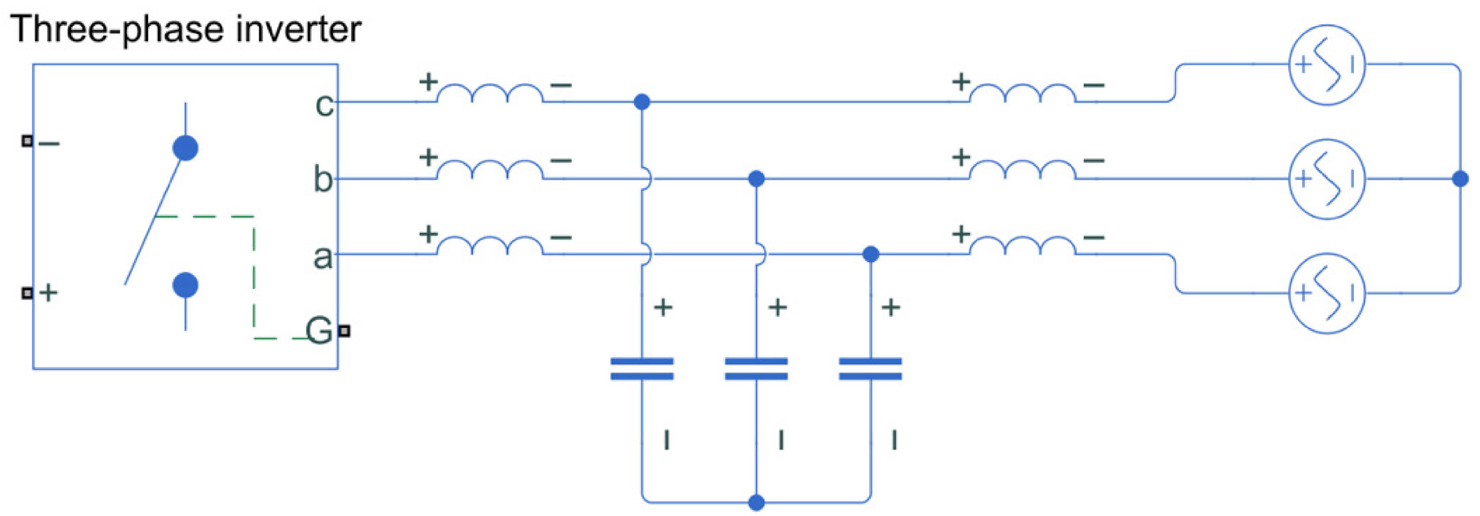
The considerations presented in the article were carried out on a grid-following converter model connected to a local power network model. The proposed system consists of the following elements: a DC voltage source, a three-phase T-type inverter, an LCL filter, and the simplified model of the power grid, which is the main load of the system. All of the energy system elements and control systems were also implemented as mathematical models in Matlab Simulink. A simplified diagram of the considered system is shown in Figure 1.

2.1. Power System Structure

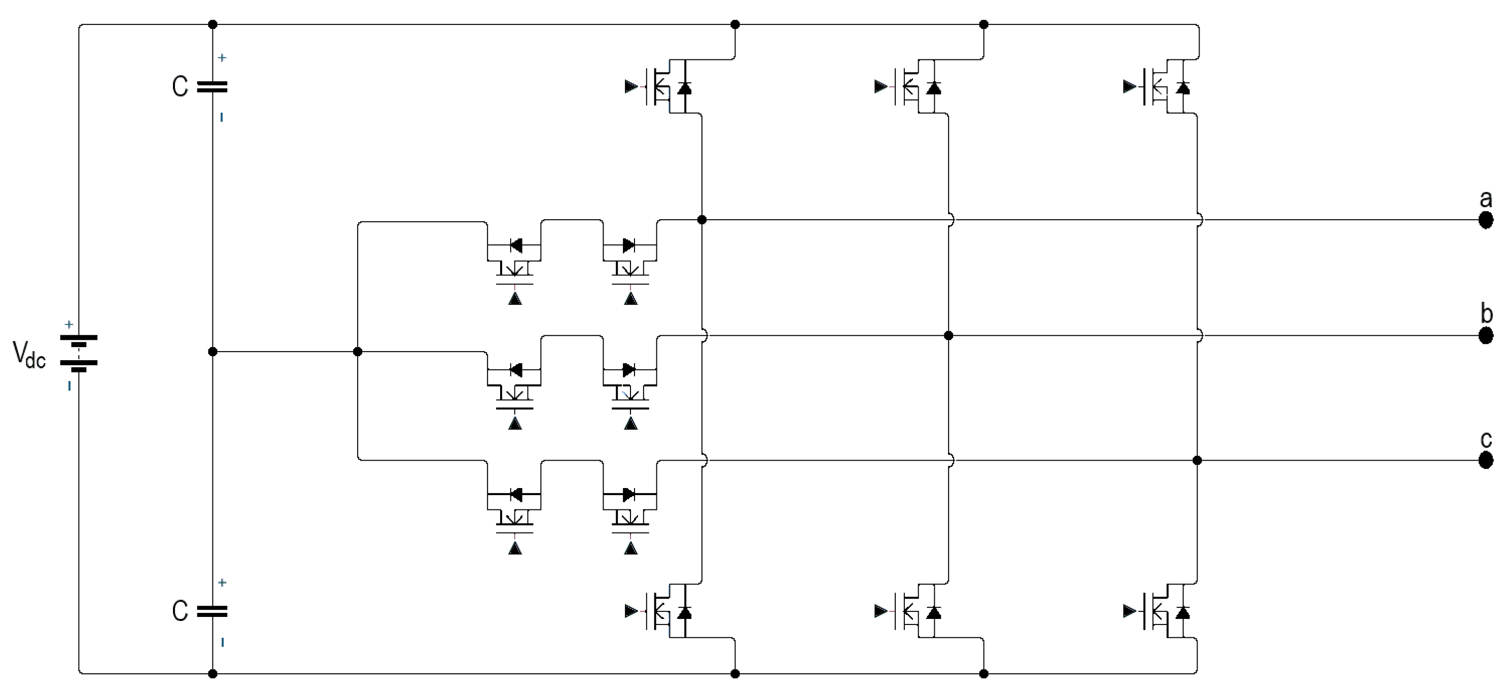
The main part of the system is the grid-following inverter. A three-phase three-level inverter in the T topology was selected for the tests. This type of topology allows a simple implementation of three-level output voltages, thanks to which the voltage signal being the output from the device gains a greater degree of flexibility [32,33]. The topology diagram of the T-type inverter is shown in Figure 2.
The proposed inverter works as a current source [34,35]. This type of converter should be connected to the power grid or to a microgrid containing a grid-forming inverter that can define the voltage and frequency conditions of the local grid. The inverter is synchronized to the grid using a Phase-Locked Loop (PLL) system [25,27,29,30,36,37,38,39,40]. The task of this device is to provide the current transferred in both directions, which is hereinafter referred to as the grid current. The DC source on the DC voltage side of the inverter can be an energy storage or; for example, a photovoltaic panel system [25,30,41]. The grid-following inverter is connected to the power grid using an LCL filter because of the discrete nature of the inverter output voltage. This type of filter is widely known and used in similar applications due to its simplicity, as well as the fact that with the appropriate selection of parameters, it is possible to ensure satisfactory filtration results at a low implementation cost [30,42,43,44,45,46].

2.2. Mathematical Model of the System

Capacitive and inductive elements are essential for describing the dynamics of the control system. The number of these elements dictates the order of mathematical equations describing the dynamics of the system. Therefore, the LCL filter used plays a very important role in the mathematical description. In the case under discussion, the parameters of this filter constitute the main basis for developing a mathematical model of the system [9,30]. Therefore, it is important to propose an appropriate control algorithm to provide protection against imperfections occurring in this mode, because deviations from the correctly selected filter parameter values can cause the occurrence of signal disturbances in the form of oscillations of higher harmonics [42,44,47]. This is strongly related to the fact that the power grid has its own inductance, which is not constant, from which follows the need to use a dedicated solution in the field of control.
Using the LCL-type filter discussed above, it is possible to propose the following equations describing the plant’s dynamics:
L d i k d t = d U d c u c k C f d u c k d t = i k i g k L g d i g k d t = u c k U g k ,
where
-
L—filter inductance;
-
L g —grid inductance;
-
C f —filter capacity;
-
i k —inverter output current of a given phase;
-
u c k —capacitive filter voltage of a given phase;
-
i g k —grid current of a given phase;
-
d—voltage modulator duty cycle;
-
U d c —energy storage voltage (inverter DC voltage source);
-
U g k —grid voltage of a given phase;
-
k—phase designation.
A simplified diagram of this model is visible in Figure 3.

2.3. Transformation of the Model Using dq0 Method

In order to simplify the control process by introducing two constant controlled signals instead of three phase signals, the dq0 transformation was used [25,41,48,49,50,51]. The use of this operation also allows for the implementation of a simple PLL synchronization system. After applying the discussed transformation, the following form of state equations can be obtained:
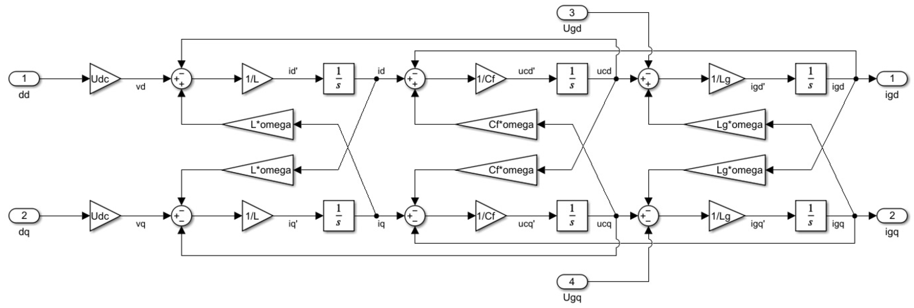
L d d t i d i q = U d c d d d q u c d u c q L ω i q i d C f d d t u c d u c q = i d i q i g d i g q C f ω u c q u c d L g d d t i g d i g q = u c d u c q U g d U g q L g ω i g q i g d ,
where
-
i d , i q —inverter output current vector components;
-
i g d , i g q —grid current vector components;
-
u c d , u c q —capacitive filter voltage vector components;
-
U g d , U g q —grid voltage vector components;
-
d d , d q —voltage modulator duty cycle vector components;
-
ω —pulsation.
It is noticeable that additional terms appeared in the equations, resulting from cross-couplings created in the system after the transformation.
The block diagram of the obtained dynamic system is visible in Figure 4. The use of the transformation allows one to consider the problem of regulation of the discussed system from the power perspective—component d is responsible for active power, and q for reactive power. This work focuses mainly on the problems of controlling the grid current in a wide range for component d, while the aim of regulation of component q is always to reduce the current of this component to the value 0, which is also a problem often discussed [52].
It is therefore a sixth-order system whose state equations can be represented in matrix form:
i d ˙ u c d ˙ i g d ˙ i q ˙ u c q ˙ i g q ˙ = 0 1 L 0 ω 0 0 1 C f 0 1 C f 0 ω 0 0 1 L g 0 0 0 ω ω 0 0 0 1 L 0 0 ω 0 1 C f 0 1 C f 0 0 ω 0 1 L g 0 i d u c d i g d i q u c q i g d + U d c L 0 0 0 0 0 0 U d c L 0 0 0 0 d d d q .
In order to design control systems, the system described by the matrix Equation (3) was divided into two smaller systems, which leads to the need of an appropriate controller for a given vector component. This action significantly simplifies the further design of controllers, and the overall dynamics of the system can still be taken into account using equivalent control laws.
For the d component of the vector, the matrix state equations take the following form:
i d ˙ u c d ˙ i g d ˙ = 0 1 L 0 1 C f 0 1 C f 0 1 L g 0 i d u c d i g d + U d c L 0 0 d d .
Similarly, the matrices for the q component can be determined.

2.4. Simulation Model

The simulation model was implemented in the MATLAB Simulink environment using elements of the specialized Simscape library. All devices were built from scratch, without using ready-made models, e.g., for an inverter. This model is therefore a realization close to reality, which can be configured in detail. A discrete solver with a time step of 1 × 10 7 was selected.

3. Implementation of Known SMC Algorithms

In order to compare the proposed control method with known literature methods, two algorithms will be first presented and described, which have already been developed in the literature and adapted to the discussed control problems. The main interest concerns the so-called reaching laws, which can have a significant impact on the control process and its quality [4,53,54,55,56,57]. The first selected method is the classic sliding mode control with a discontinuous (switching) part, proportional reaching law and equivalent control. The second algorithm is HSMC—hybrid control, in which the proportionally reaching law is switched with a power reaching law, and the discontinuous control has a variable amplitude.

3.1. Sliding Variable Selection

The first, and most important step in sliding mode control algorithm design is the appropriate proposal of the form of the hyperplane and its coefficients. As mentioned above, the dynamics of the system in the sliding phase will be governed solely by the adopted hyperplane. There are several methods for the appropriate selection of these coefficients, such as pole placement method, quadratic optimization, etc., but also using the dead-beat method [5,15]. In the implementation examples of sliding mode control in the grid current control system using a three-phase inverter known from the literature, the method of selecting these parameters is based on manual selection of values that are experimentally proven to provide stability of the system [30]. An additional difficulty in using some analytical methods is the fact that the state variables are not phase variables. In the two discussed cases, the manual method was used, but its stability was confirmed by using the state matrix described in Section 2, which is presented in the next subsection. Therefore, the following two sliding variables were selected:
s d = c 1 ( i d i d s e t ) + c 2 ( u c d u c d s e t ) + c 3 ( i g d i g d s e t ) ,
s q = c 1 ( i q i q s e t ) + c 2 ( u c q u c q s e t ) + c 3 ( i g q i g q s e t ) ,
where
-
s d , s q —sliding variables;
-
c 1 , c 2 , c 3 —sliding variable coefficients, where c 1 > 0 , c 2 > 0 , c 3 > 0 ;
-
i d s e t , u c d s e t , i g d s e t , i q s e t , u c q s e t , i g q s e t —desired values of the state variables.

3.2. Stability Analysis

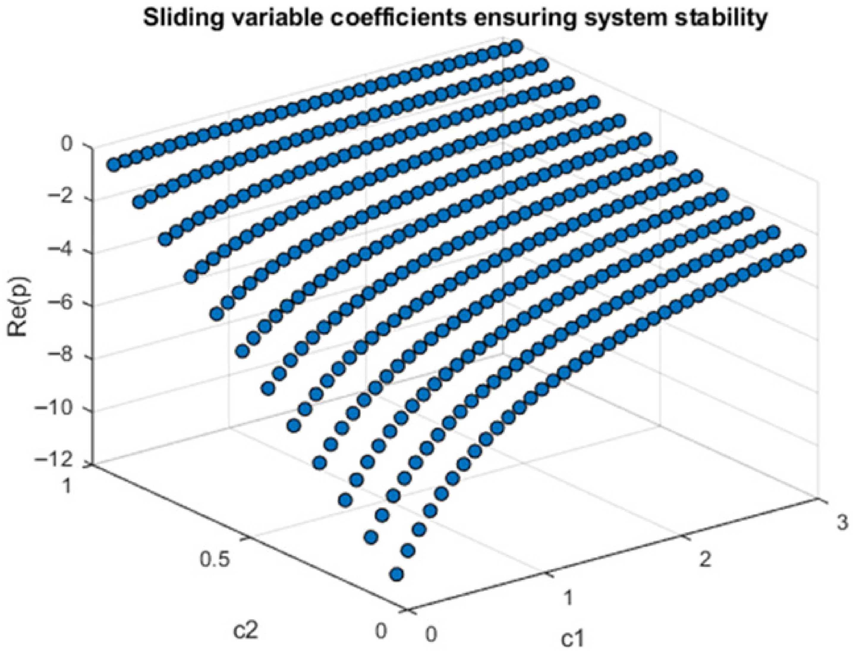
In order to investigate the stability of the system, the state feedback with the equivalent control substitution was applied, which led to obtaining a closed matrix of the system with the equivalent control applied. The stability of the system was investigated based on determining the poles of this system depending on the applied coefficients of the sliding variable, the combination of which was checked to a certain extent [58]. On this basis, a graphical visualization of the three-dimensional space was obtained, showing stable combinations of hyperplane parameters. The values of the slowest modes were presented. The aforementioned visualization is visible in Figure 5. The following sliding variable cofefficient values were selected: c 1 = 0.5 , c 2 = 1 , and c 3 = 1 .

3.3. Implementation of a Classic SMC

The structure of the classical controller is based on a discontinuous part, implemented using the sign function and equivalent control, which results from the dynamics of the plant. Additionally, the so-called reaching law has been taken into account in the form of a very simple, proportional part of the control law. The controllers for both components of the vectors are designed in an analogous way; therefore, the derivations of equations for the d component only have been presented.
In order to determine the equivalent control, Lyapunov stability analysis can be used, with the following Lyapunov function [9,30]:
V d = 1 2 s d 2 ,
will be reduced to the form of the well-known stability condition of a sliding-mode control system:
V d ˙ = s d s d ˙ < 0 .
The controlled variable in the case of the discussed issue is the output voltage of the inverter, which can be presented as the dependence of the control signal on the source voltage on the DC side of the inverter and the duty cycle [9,30]:
v d v q = U d c d d d q ,
where
-
v d , v q —components of the inverter output voltage vector.
Finally, the form of equivalent control for the d component can be presented in the following form [9]:
u d e q = L U d c u c d + L ω i q L i d s e t L c 1 c 2 U d c i d i g d + C f ω u c q C f u c d s e t L c 1 c 3 U d c u c d + L ω i g q L i d s e t .
Taking into account the obtained equivalent part in the control law, the following full form of the control [9] can be obtained:
u d = k 1 sgn ( s d ) k 2 s d + u d e q ,
where
-
u d —control law for the d component;
-
k 1 , k 2 —positive gains for corresponding control law parts.
Such a control algorithm ensures Lyapunov asymptotic stability, which is shown in the following equation:
V d ˙ = s d k 1 sgn ( s d ) k 2 s d < 0 .
Similar derivations apply to the q component.

3.4. Implementation of a Hybrid SMC

One of the interesting approaches is the use of so-called hybrid controllers, in which a certain part of the control law changes depending on the fulfillment of certain conditions [8,9]. In the case presented in this subsection, this is a change in the type of the reaching rule, the switching of which takes place at the representative point, which allows to avoid step changes in the control signals [9]. In the discussed case, two types of reaching rules are switched: proportional and power. The power reaching rule is used in the regions of state space far from the hyperplane, which allows to reduce the duration of the reaching phase. In the area closer to the hyperplane, the proportional part is activated, since it tends to provide better results with lower values of the sliding variable [8,9]. Additionally, the amplitude of the discontinuous part is variable and depends on the value of the sliding variable and the appropriate parameter. Such a procedure is intended to reduce the influence of chattering, which has been confirmed in the literature [9,12].
Again, it is possible to apply the methods used for the implementation and analysis of classical SMC, only changing the reaching law and the discontinuous control [9]:
u d = k 1 | s d | 1 α sgn ( s d ) k 2 H s d , α + u d e q ,
where
-
α —an additional parameter for hybrid control law;
-
H s d , α –-an additional function to implement hybrid control type, expressed by equation:
H s d , α = | s d | 1 + α sgn ( s d ) for | s d | > 1 , H s d , α = s d for | s d | 1 .
The presented control law again ensures asymptotic stability in the Lyapunov sense:
V d ˙ = s d k 1 | s d | 1 α sgn ( s d ) k 2 H s d , α < 0 .

3.5. Results Presentation

In order to initially compare both methods, a very simple test scenario case consisting of setting a constant signal value of 5 A is proposed for the desired value of the d component of the grid current vector.
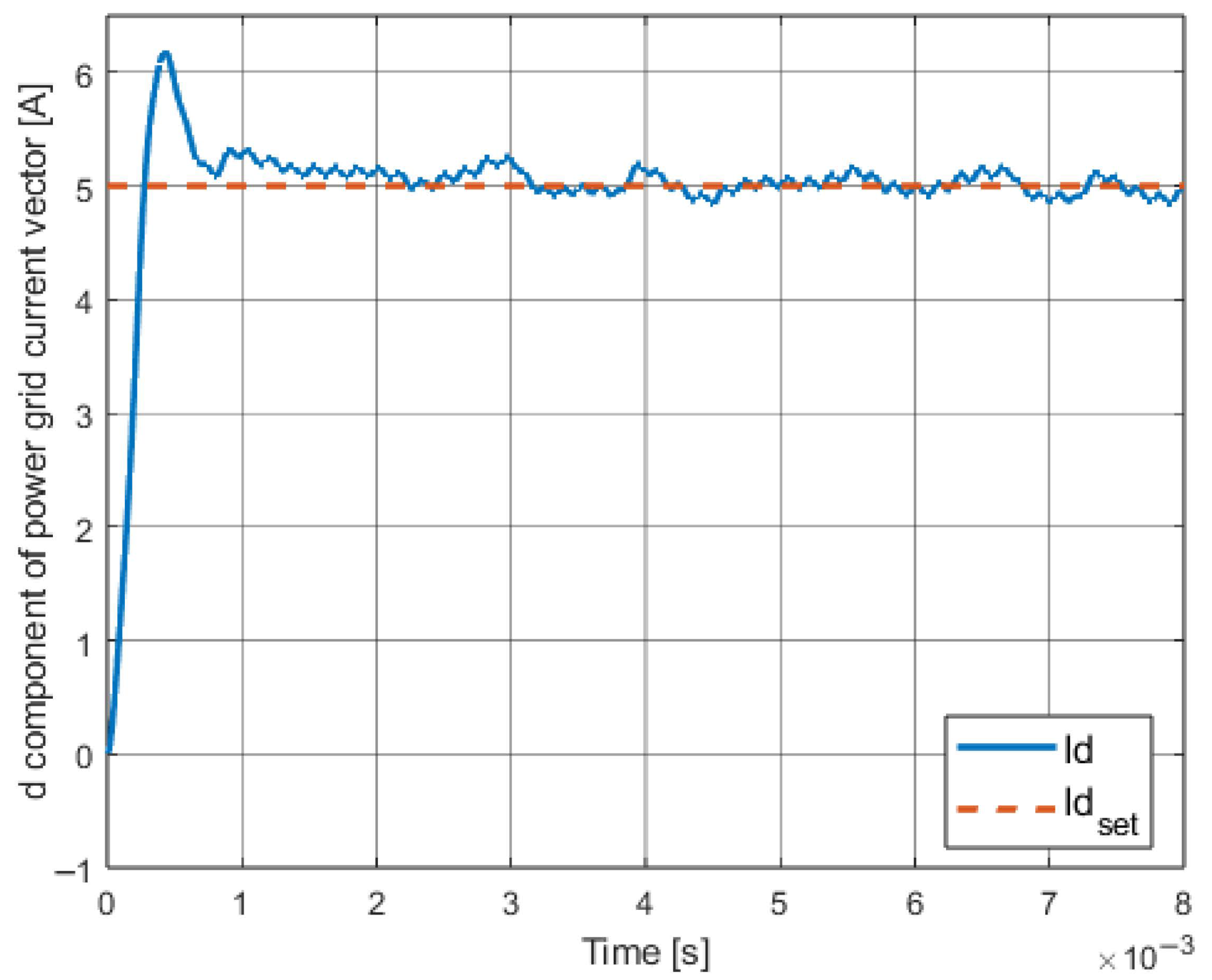
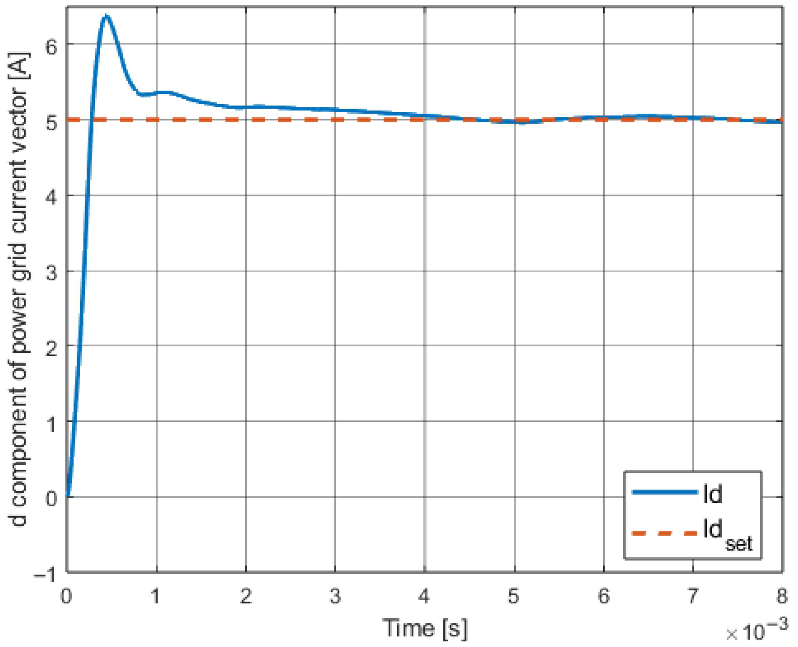
The results for both methods are presented below. Two types of waveforms are presented for the d component of the grid current vector: for a short simulation time to show the beginning of the control process and for a longer simulation time to demonstrate the steady state behavior. Additionally, sliding variable waveforms for each controller case are visualized. Figure 6 and Figure 7 present graphs of the d components of the grid current vector and their given signals for the case of using the classic SMC from Equation (11) and the hybrid HSMC described by Equation (13), respectively. As mentioned earlier, this is the first type of waveform that concerns a short simulation time in order to visualize the dynamic stage itself, i.e., the reaching phase.
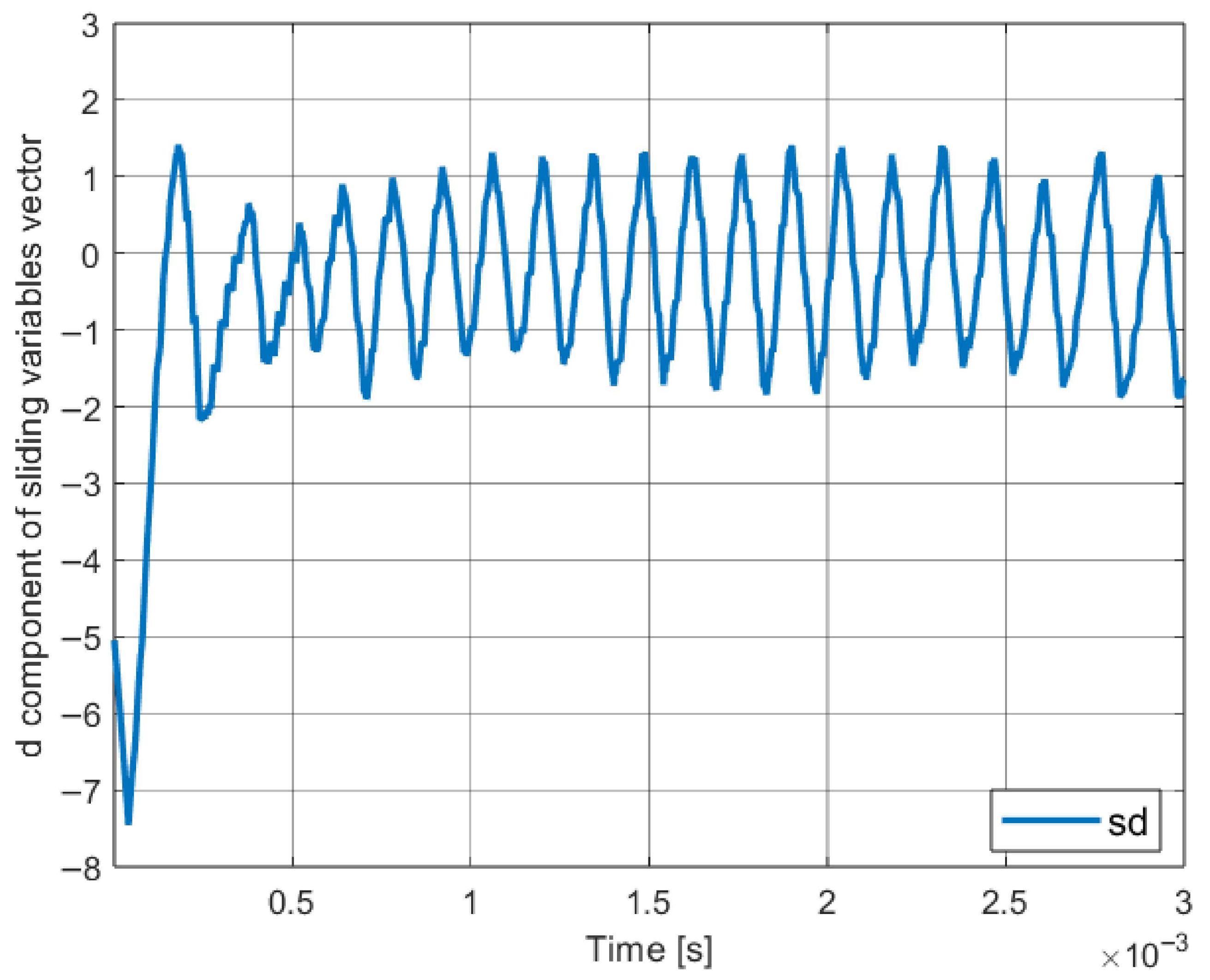
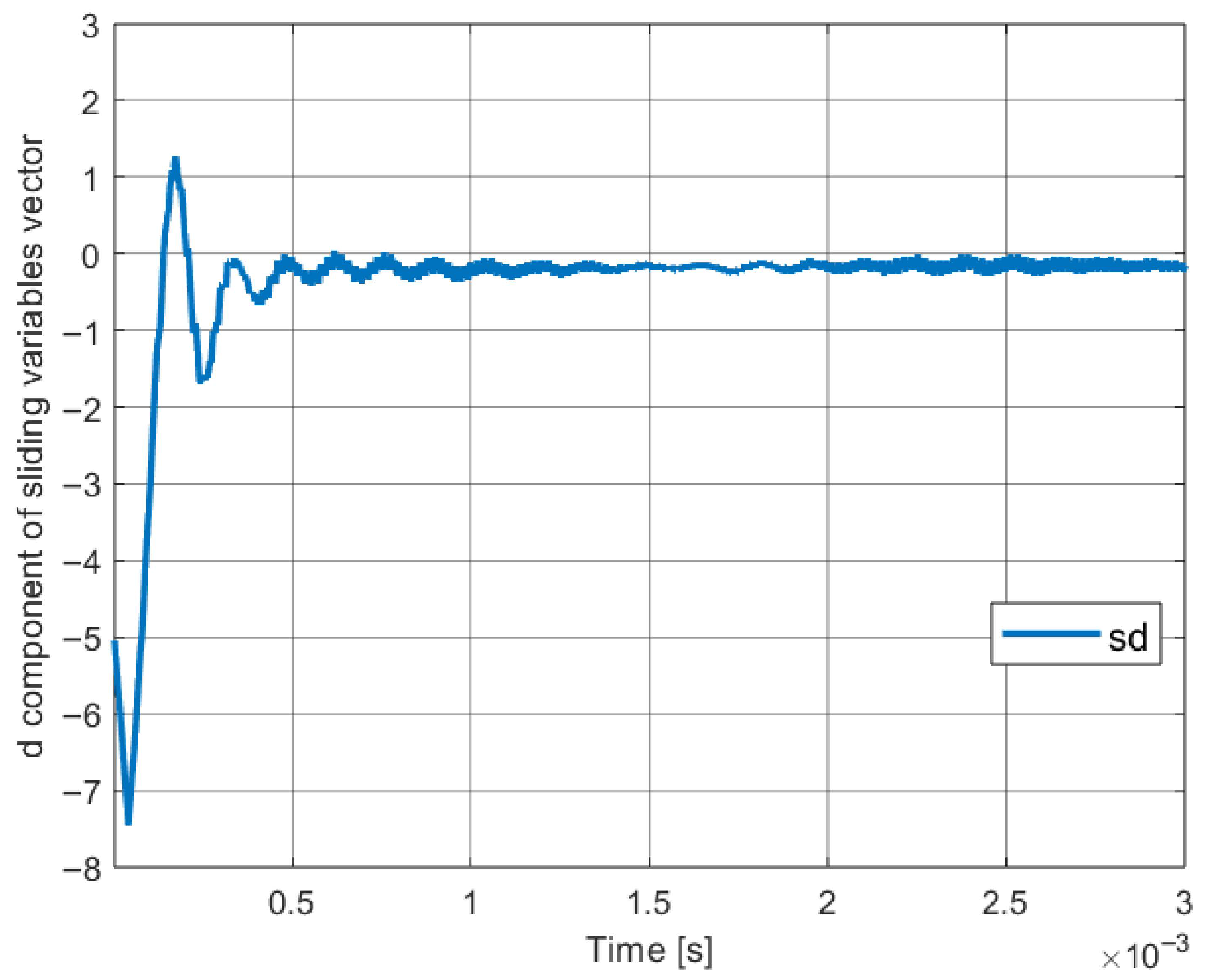
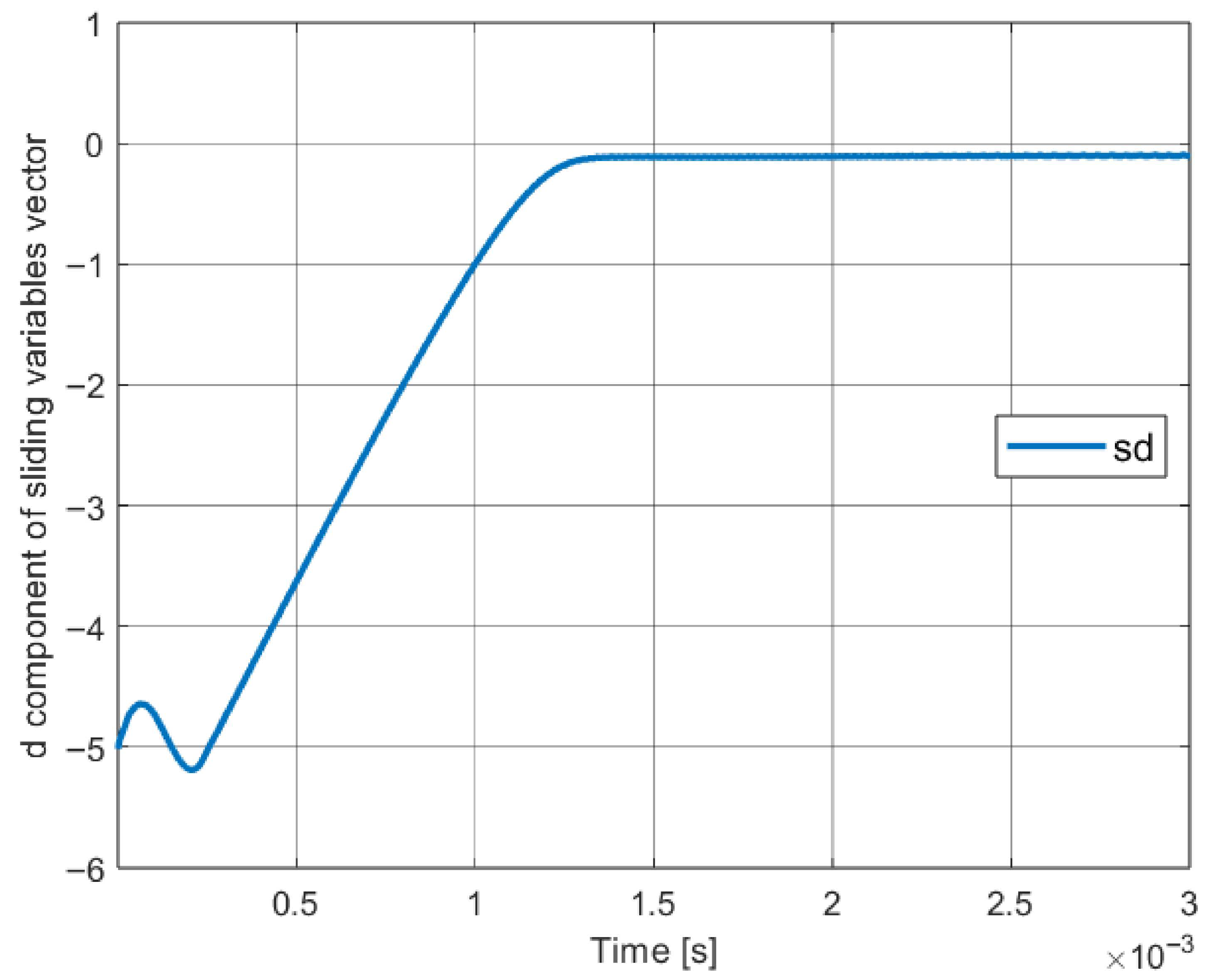
The waveforms visible in Figure 8 and Figure 9 allow to observe sliding variable signals. One can see that for the first case, i.e., for the classic sliding mode control approach, the impact of the chattering phenomenon resulting from discontinuous control presence. On the other hand, the second figure mentioned shows that this impact may be indeed reduced using hybrid reaching law and variable amplitude of the switching control part.
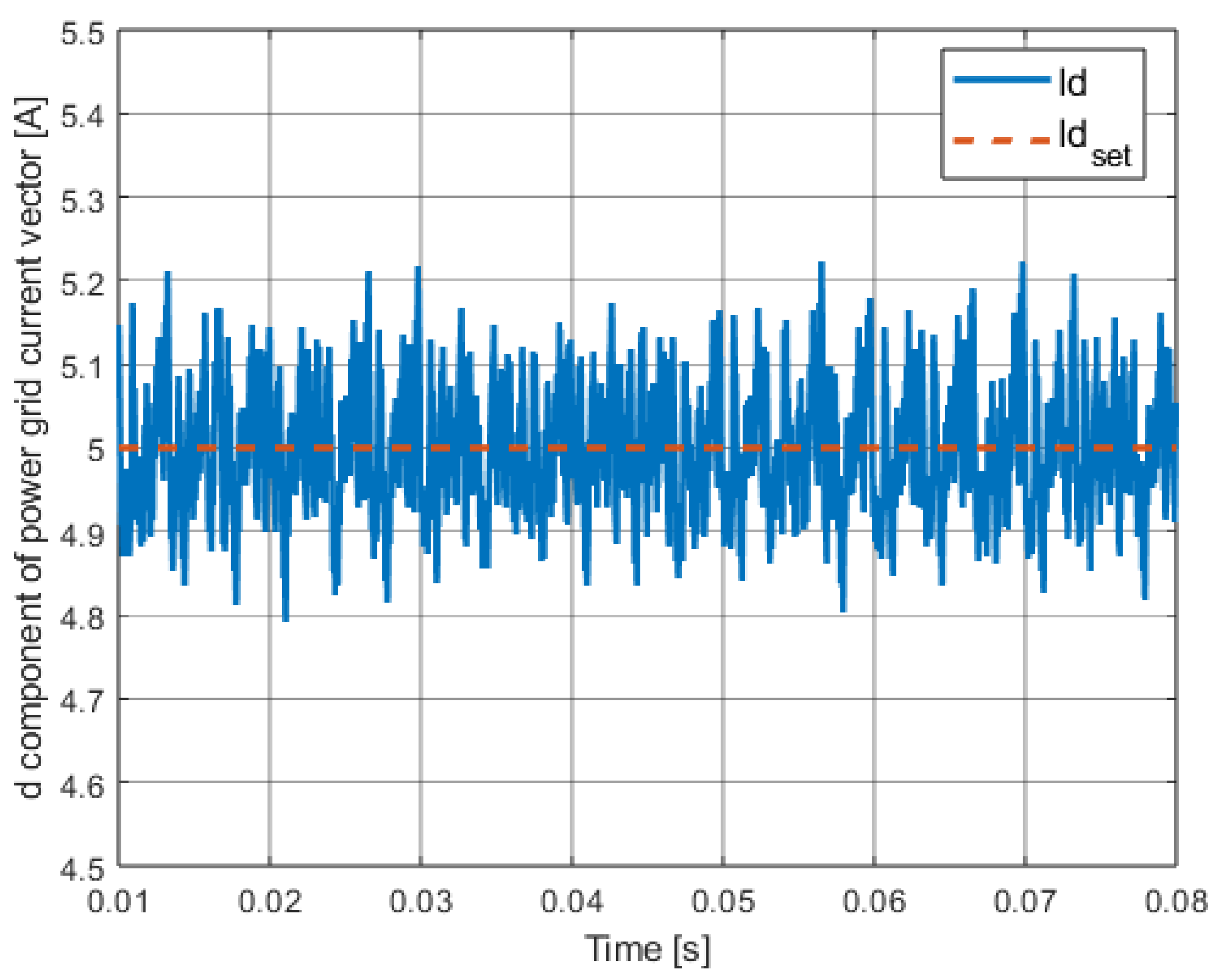
The observable oscillations resulting from the presence of discontinuous control, which are shown in Figure 10, were significantly reduced by means of hybrid control, and specifically by using the implementation of variable amplitude discontinuous control, which is visible in Figure 11. As mentioned earlier, only the oscillations resulting from the operation of the inverter keys remained (6th harmonic). This is a state close to the expected one. Reducing the amplitude value of these oscillations even to a greater extent is one of the goals of using more sophisticated methods presented in the subsequent chapters of the work.

3.6. Conclusions About Known Solutions

In both cases of the implementation of control algorithms based on sliding methods, the system turned out to be stable and the results were satisfactory. The use of the classical algorithm meets the basic requirements regarding the quality of control; however, a visible drawback is the presence of the chattering phenomenon, which is reduced to the presence of low-amplitude and high-frequency oscillations in the controlled signal of the system [1,4]. The hybrid control algorithm allows for obtaining better results by using the appropriate switching of reaching law and the variable amplitude of discontinuous control, thanks to which the impact of the chattering phenomenon on the system is significantly reduced. However, the proposed solutions also have a number of disadvantages. Firstly, the lack of possibility of using known analytical methods for selecting the coefficients of sliding variables—some methods are not applicable due to the previously mentioned fact of non-phase state variables, and, for example, the method based on dead-beat is not possible to implement due to the generation of too high signal values in the system, which shall lead to instability. It would be possible to use the pole placement method, where the starting point would be dead-beat control, but this is still a manual operation to some extent. The effect of manual selection of hyperplane parameters is most likely the overshoot visible in Figure 6. Secondly, these are continuous methods, and a better solution would be to use discrete control assuming the use of digital systems. Another problem is the use of certain quantities that are not fully analytically confirmed in the literature, but are present in the control laws in the form of gains. It is true that in the case of continuous controllers, the gain of discontinuous control should be greater than the total values of disturbances acting on the system [2]. In order to reduce the impact of the mentioned control system weaknesses on the system, a more advanced sliding control method is proposed in the next chapter.

4. Nonswitching-Type Reaching Law Implementation

In this section, a method for designing a nonswitching reaching rule based on [5] is presented. Then, this method is implemented in the system and its operation is checked. This algorithm belongs to the category of discrete controllers; hence, the system has been discretized. Interestingly, in this method there is no discontinuous switching part included; hence, the chattering phenomena problem should be completely eliminated. This method is designed to use a sliding hyperplane obtained with the dead-beat approach [5,16,55,56]. The selection of the sliding variable coefficients based on the dead-beat approach allows obtaining a hyperplane that shall provide the fastest error reduction, and the reaching law itself is designed in such a way as to appropriately limit the control signal, which could reach very high values without this limitation. The algorithm also allows for taking into account compensation for external disturbances and model imperfections using estimated maximum values of the deviations of these phenomena from the average values.

4.1. Dead-Beat Approach

In order to use the nonswitching reaching law method with the dead-beat hyperplane design approach, the system model was discretized. Two reduced matrices were used, which greatly simplified the discretization process. The discrete state matrix for the d component took the following form:
A d = A d 11 A d 12 A d 13 A d 21 A d 22 A d 23 A d 31 A d 32 A d 33 .
Due to the size of the above matrix, its individual elements are presented in Appendix A. The presented matrix will also be quoted later in the context of introducing the adaptation mechanism to the discussed control method.
To obtain the coefficients of the sliding variable using the dead-beat approach, one must determine the vector c T from the following equation:
det z 0 0 0 z 0 0 0 z 1 0 0 0 1 0 0 0 1 B d c T B d 1 c T A d = z 3
where
-
B d —discrete input matrix;
-
c T —sliding variable coefficients vector, c T = c 1 c 2 c 3 .
Determining the discussed coefficients is greatly facilitated by dividing the entire matrix system of equations into two simpler ones—this resulted in obtaining two third-order systems, hence the matrix for each component is compared to z 3 .

4.2. Control Law Implemenation

To determine the control law based on the nonswitching reaching law type, it is necessary to define sliding variables in the discrete domain:
s d ( k ) = c 1 [ i d ( k ) i d s e t ( k ) ] + c 2 [ u c d ( k ) u c d s e t ( k ) ] + c 3 [ i g d ( k ) i g d s e t ( k ) ] ,
where
-
s d ( k ) —sliding variable for the d component,
-
i d ( k ) , u c d ( k ) , i g d ( k ) —discrete state variables,
-
i d s e t ( k ) , u c d s e t ( k ) , i g d s e t ( k ) —desired discrete state variables signals.
For this chosen definition of the sliding variable, the control law based on the nonswitching reaching law type has the following form:
u d N R L ( k ) = c T B d 1 1 q [ s d ( k ) ] s d ( k ) + c T A d x d ( k ) c T x d set ( k ) + c T B d 1 F 1 d S 1 d ,
where
-
u d N R L ( k ) —control law based on nonswitching reaching law type;
-
q [ s d ( k ) ] —reaching law function; q [ s d ( k ) ] = s 0 d s d ( k ) + s 0 d ; where s 0 d —a positive constant;
-
F 1 d —average value of the disturbances impact on the system;
-
S 1 d —average value of the model inaccuracy impact on the system.
The control law presented above, together with an analogous control signal for the q component, has been implemented in the simulation environment. It should be noted that the equivalent control is largely implemented by state feedback; however, the existence of cross-couplings feedback is ignored, but it can be taken into account by using the appropriate constants that refer to the model inaccuracies and that are included in the control law.
Due to the use of a hyperplane designed with the dead-beat approach, three separate simulation models with different levels of advancement and complexity were designed:
-
Mathematical model—The simplest model, which was built using the matrix equations presented earlier. It concerns only one component of the grid current vector. Only basic Simulink elements were used in the design of this system. This model is helpful in verifying control based on the dead-beat method.
-
Model with ideal voltage sources—This is a model that takes into account both components of the state variable vectors. For this reason, it contains dq0 transformation systems and a synchronization system. The LCL filter and the power grid are implemented using elements of the Simscape library, which allows for the implementation of electrical elements in a very precise way. Reference voltages are implemented using ideal voltage sources, which allows for testing a fairly advanced version of the system in the absence of control signal constraints and for any output voltage levels.
-
Full model, i.e., model with modulator and inverter—This is the most advanced version of the model, which extends the previous model with modulator and inverter, which are also implemented using electrical elements of the Simscape library. Due to the mentioned elements, there are restrictions on the control signal in the system, and the T-type inverter—as a three-level inverter—can realize three voltage levels at the output: positive, zero and negative. This is the model used to conduct series of tests to generate results presented in this paper, also including tests of classic and hybrid control, which were described in the previous chapters.

4.3. Stability Analysis

Based on [5] it is possible to ensure the stability of the system using such a control law by fulfilling the following condition:
s 0 d > S 2 d + F 2 d ,
where
-
S 2 d —maximum permissible deviation of the value of the impact of model inaccuracy on the system from the nominal value;
-
F 2 d —maximum permissible deviation of the value of the impact of external disturbances on the system from the nominal value.
Both sets of parameters: above S 2 d and F 2 d and also mentioned in (19) S 1 d and F 1 d refer, respectively, to the total effect of the model uncertainty and external disturbances on the system:
S d ˜ ( k ) = c T Δ [ x d ( k ) ] ,
where
-
Δ [ x d ( k ) ] —a model uncertainty representation.
F d ˜ ( k ) = c T f ( k ) ,
where
-
f ( k ) —an external disturbance.
First, the control algorithm based on the dead-beat method (without nonswitching reaching law) was tested on a discrete mathematical model. After achieving success, tests were carried out on the second level of model advancement, also obtaining a positive result. The full technical model could not work correctly (in the context of simulation) due to the limitations of the inverter and the DC source, which led to exceeding the limits of the control signals and, as a result, to instability. Taking into account the full control law from (19) allowed to limit the control values in an expected way, so that the control task could be realized using the full technical model that was closest to reality.
In the case of control process discussed in this paper it is possible to introduce assumptions regarding above-described effects:
(1)
The total effect of the model uncertainty results from the lack of inclusion of the cross-couplings in the control algorithm and also results from all phenomena resulting from the use of advanced electronic components in simulation environement, whose full mathematical description would be too complex, i.e., parameters of transistors, passive elements, parasitic values, etc.
(2)
The total impact of disturbances acting on the system can be assumed arbitrarily to some extent, taking into account additionally the experimentally observed oscillations resulting from the operation of transistors, focusing on the value of their amplitude based on Figure 11. Since there is no external disturbance applied, it is possible to use the discussed signal in this manner.
In the first case, the signal may be specifed by considering the impact of the components added in (2) in relation to (1). To obtain values from (19) and (20), which refer to the average values and maximum deviations, assumptions regarding the test scenario must be made and then these signals can be measured.
Taking into account that
S 1 d = S U d + S L d 2 , F 1 d = F U d + F L d 2 ,
S 2 d = S U d S L d 2 , F 2 d = F U d F L d 2 ,
where
-
S U d —upper bound of S ˜ d ( k ) ;
-
S L d —lower bound of S ˜ d ( k ) ;
-
F U d —upper bound of F ˜ d ( k ) ;
-
F L d —lower bound of F ˜ d ( k ) .
It is possible to redirect the analysis of the discussed impacts to determine, through appropriate assumptions, their maximum and minimum values.
One can see that missing control law elements, resulting from the lack of inclusion of the cross-couplings, can be found in the full equivalent control from (10). Considering observations mentioned above, the following form of (21) may be proposed for c T B d 0 :
S d ˜ ( k ) = L ω U d c i q ( k ) + u c q ( k ) c 1 c 2 + i g q ( k ) c 1 c 3 c T B d 1 .
The obtained Equation (25) describes the total effect of one vector component (q) to another one (d). Based on that it is possible to propose appropriate assumptions or deliver experimental data regarding quantities presented in (24). As for (22), without any known external disturbance impacting the system, the best solution is to take into consideration observed oscillations amplitude.

4.4. Obtained Results

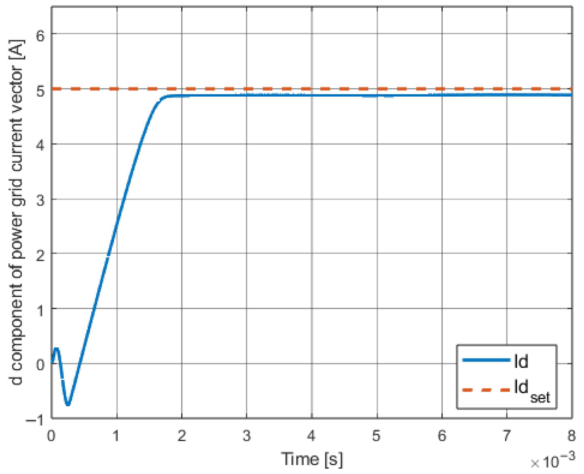
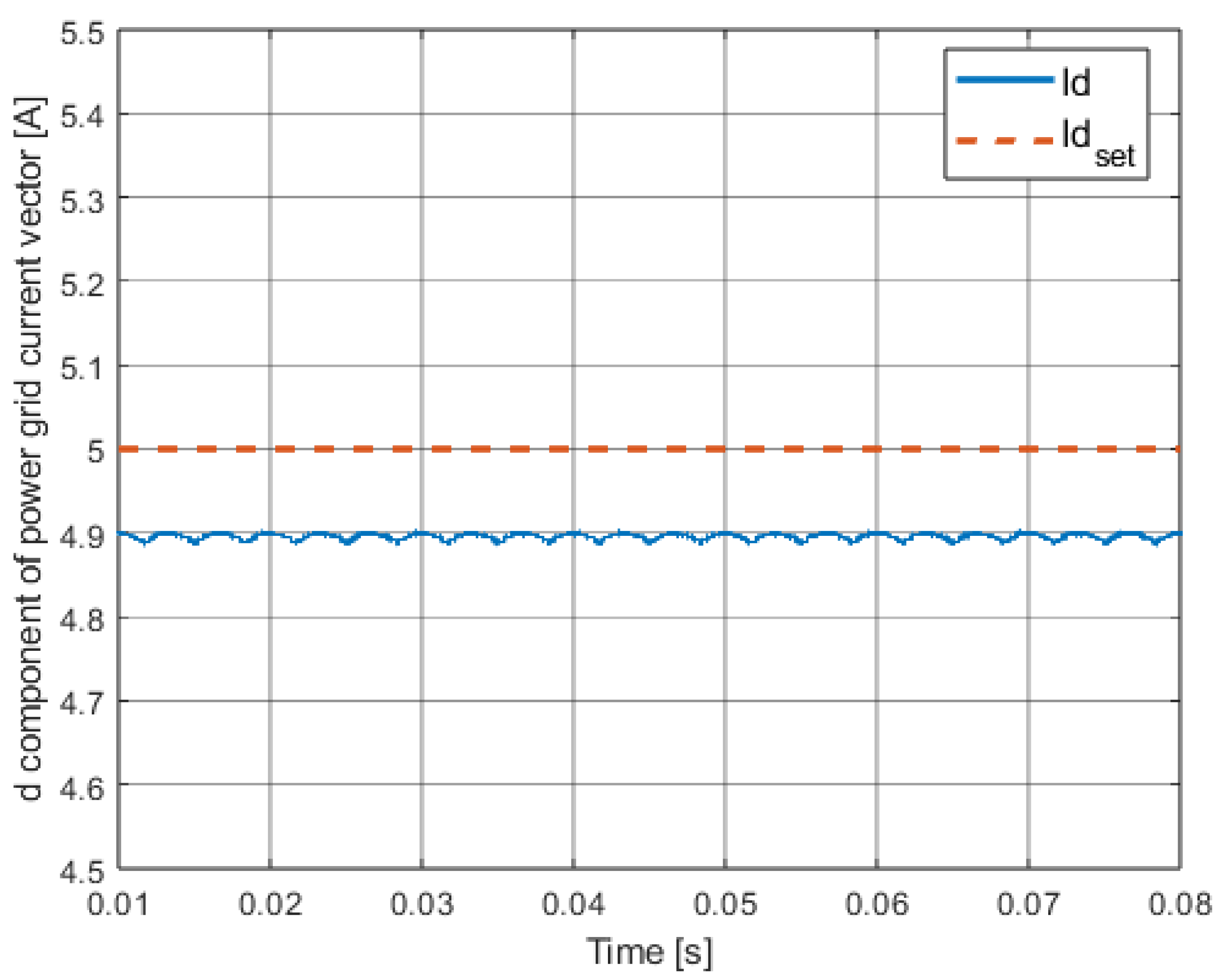
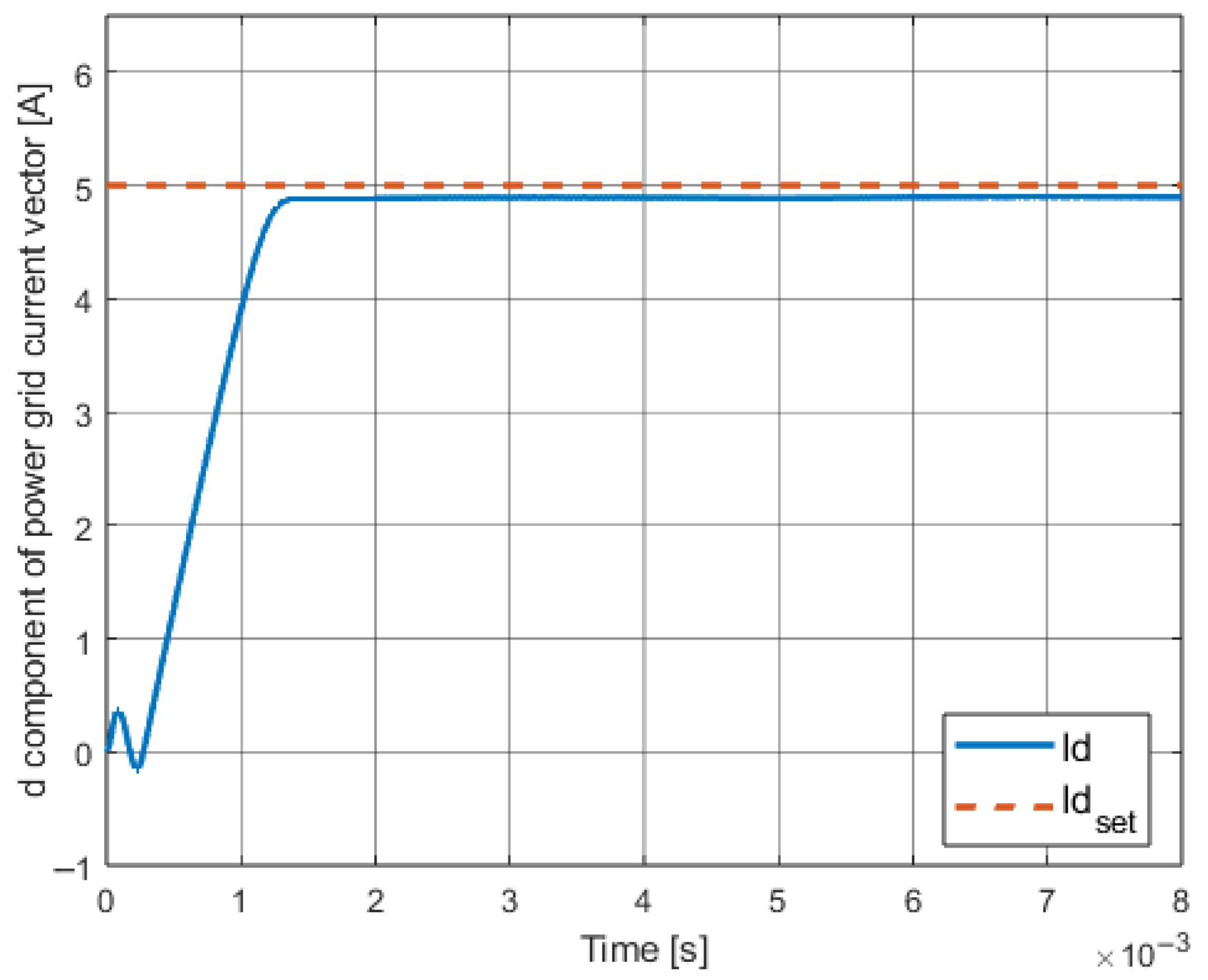
Similarly to Section 3.5, the results of the simulation tests are presented below, maintaining the same form. The control law parameter ( s 0 d ) was selected arbitrary based on (20) condition. The waveform shown in Figure 12 differs significantly from those presented in Figure 6 and Figure 7—there is no overshoot, and it is also possible to observe a completely different waveform characteristic. The same conclusions apply to results presented in Figure 13 when compared with those from Figure 8 and Figure 9. In turn, in Figure 14 one can see that, although the amplitude of oscillations resulting from the operation of the inverter keys decreased, a significant steady-state error appeared. The obtained results are described in more detail in the next subsection.

4.5. Conclusions About the Method

The applied solution allowed for the obtainment of a very good quality signal of the controlled value. It is free of oscillations and noise visible for the classical method, and there is no overshoot. The reaching phase is characterized by an almost linear characteristic of the grid current of the d component. The similar linearity itself can be a serious advantage in many different implementations and fields, especially since the set signal is constant.
It is worth mentioning that the characteristic of the sliding variable waveform, visible in Figure 13, is significantly different from those previously obtained (Figure 8 and Figure 9). The signal in this case is smooth and mostly close to a linear shape during reaching phase. No chattering is visible, but non-zero error in steady-state can be observed.
It is possible to point out several aspects of the control law in question that could be changed or modified, namely
a.
In the case of the above results, the parameter s 0 d is based entirely on the condition presented in (20), i.e., its value was assumed arbitrarily in the range specified by the condition. This parameter directly affects the gain of the control signal and thanks to it, it is possible to inhibit the dead-beat control to a greater or lesser extent. Hence, its appropriate selection for the assumed operating conditions could improve the quality of the control process. This problem is the genesis of the introduced adaptation mechanism, which will be presented in the next chapter.
b.
There is a steady-state error in the system, which can be seen in Figure 14. This error in long-term processes may turn out to be a factor significantly reducing the potential quality of control. This problem, in turn, is the basis for using the method of reducing the steady-state error proposed in Section 6.

5. Introducing Adaptation Mechanism

The presented control law described by Equation (19) assumes the use of a sliding variable resulting from the dead-beat method. It follows that the key aspect in such a control algorithm is to propose a model with high accuracy of plant representation. The methods presented above for limiting the value of the control signal to the maximum control value can be extended to take into account the occurrence of changes in specific model parameters within a certain assumed range. One of the proposed solutions for selecting the parameter s 0 d may be to link this parameter to a certain maximum value of the control signal. In the case of using an inverter with a modulator, the range of the control signal is [ 1 , 1 ] , so the maximum absolute value of the control, which is equal to 1, can be used as follows:
u d N R L ( 0 ) | u d m a x | ,
where
-
u d m a x —maximum allowable control.
Using the condition given in (26) and based on Equation (19), it is possible to present the following condition regarding the parameter s 0 d :
s 0 d c T x d set ( 0 ) | u d m a x | c T B d c T A d x d ( 0 ) s d ( 0 ) + 1 | s d ( 0 ) | c T x d set ( 0 ) | u d m a x | c T B d c T A d x d ( 0 ) s d ( 0 ) .
Based on this condition, it is possible to determine the appropriate control parameter, which ensures that the signal value at the first moment of time will not exceed the maximum value. This means that it is possible to use the dead-beat sliding hyperplane justifiably. Moreover, the efficiency of the control system can be maintained by implementing a fast and stable regulation process.
To confirm the reasonableness of the above assumptions, a simulation test was performed again, this time for the newly determined parameter s 0 d , in the Section 5.2.

5.1. Description of Adaptation Aspects

Using the method for determining the range of the non-switching control parameter, it is possible to propose a certain modification of the control based on the adaptation mechanism. Taking into account the dependencies between the parameter s 0 d and the maximum value of the control signal, state variables and setpoint signals contained in the inequality (27), it is possible to introduce regular updates of the value of this parameter so as not to exceed the control limits, while maintaining the parameter value calculated for the maximum control value.
An additional aspect worth considering is the limitation resulting from the nature of the object itself. In this case, it is possible to narrow the range of the control law parameter based on certain assumed ranges of changes in the grid parameters, i.e., the main load of the system. In the discussed case, the most important thing will be to take into account the variation in the grid capacitance and inductance. However, this method can also be used for any other plant in which a variation in certain parameters, loads or disturbances may be expected.
For the following conditions:
L g L g δ ,
C f C f δ ,
where
-
L g δ —new inductance value related to the grid load changes;
-
C f δ —new capacity value related to the grid load changes.
It is possible to propose a new state matrix in which the changed grid parameters are taken into account. First, however, an indication what exact impact a change in the value of a given parameter may have on other parameters is needed:
-
an increase in the grid inductance value leads to the need to increase the value of the control signal for a constant s 0 d ;
-
an increase in the capacitance value leads to the need to increase the value of the control signal for a constant s 0 d ;
-
an increase in the value of the parameter s 0 d leads to an increase in the value of the control signal (the larger s 0 d , the less dead-beat is counteracted).
A d δ = A d 11 δ A d 12 δ A d 13 δ A d 21 δ A d 22 δ A d 23 δ A d 31 δ A d 32 δ A d 33 δ .
where
-
A d δ —discrete state matrix with changed inductance and capacity (individual elements are presented in Appendix B).
Hence, one can conclude that in order to maintain the control signal value within a certain limited range, it is possible to use an additional limitation of the parameter s 0 d due to the assumed maximum values of inductance and capacitance. This is because it is the increase in these values that leads to exceeding the control signal limits. Hence, the values introduced in Equations (28) and (29) actually refer to the maximum values. Reducing either of these parameters will lead to a decrease in the control value, but within a safe range. Therefore, the parameter s 0 d has been additionally limited due to the assumed maximum values of the grid parameters in such a way that the maximum control value is achieved for the maximum possible values of the changed grid parameters.
If, in accordance with the previous statements, an increase in the value of the grid parameters leads to an increase in the value of the necessary control, then the action of the adaptation mechanism should consist of decreasing the value of the parameter s 0 d in order to reduce this control and maintain it within the assumed range or to adopt its assumed value.
By using a constant value of the parameter s 0 d , it is possible to determine the difference in the control value for two different state matrices:
δ u d m a x = c T B d 1 c T A d A d δ x d ( 0 ) ,
However, since the intended goal is to introduce adaptation of the parameter s 0 d , the range of the control value should always end at the maximum value resulting from the plant’s specificity. Hence, it is possible to update the inequality (27) to take into account the assumed range of grid parameter variability:
s 0 d δ c T x d set ( 0 ) | u d m a x | c T B d c T A d δ x d ( 0 ) s d ( 0 ) + 1 | s d ( 0 ) | c T x d set ( 0 ) | u d m a x | c T B d c T A d δ x d ( 0 ) s d ( 0 ) .
where
-
s 0 d δ —changed control parameter taking into account the assumed range of grid parameter variability.
The inequality (32) is an improved form of the inequality (27) that takes into account the grid variability that affects the model. This is very important when using the state matrix feedback based on the dead-beat method.
Based on the assumed largest and smallest necessary changes in state variables resulting from the current and desired states, it is possible to determine the limits of the signal being a variable representation of the parameter s 0 d δ . These limits should take into account the previously described assumptions regarding the range of changes in the grid and filter parameters.
For max c T A d x d ( 0 ) + c T x d set ( 0 ) = ϕ m a x :
s 0 d δ m i n = ϕ m a x | u d m a x | c T B d s d ( 0 ) + 1 | s d ( 0 ) | ϕ m a x | u d m a x | c T B d s d ( 0 ) ,
where
-
ϕ m a x —an auxiliary constant expressing maximum value of the respective control law parts;
-
s 0 d δ m i n —a constant defining the lower limit of the control law parameter value with respect to the value of ϕ m a x .
For min c T A d x d ( 0 ) + c T x d set ( 0 ) = ϕ m i n :
s 0 d δ m a x = ϕ m i n | u d m a x | c T B d s d ( 0 ) + 1 | s d ( 0 ) | ϕ m i n | u d m a x | c T B d s d ( 0 ) ,
where
-
ϕ m i n —an auxiliary constant expressing minimum value of the respective control law parts;
-
s 0 d δ m a x —constant defining the upper limit of the control law parameter value with respect to the value of ϕ m a x .
Using the inequality (20) presenting the proof of stability, it is possible to present the following condition:
s 0 d δ m a x s 0 d δ m i n > S 2 d + F 2 d .

5.2. Adaptation Mechanism Implementation

By adopting the above-mentioned assumptions described by equations and inequalities (26)–(35), it is possible to propose the following mechanism for adapting the parameter s 0 d δ ( k ) :
s 0 d δ ( k ) = s 0 d δ m a x for s 0 d δ ( k ) s 0 d δ m a x ϕ ( k ) | u d m a x | c T B d s d ( k ) + 1 | s d ( k ) | ϕ ( k ) | u d m a x | c T B d s d ( k ) for s 0 d δ ( k ) s 0 d δ m i n ; s 0 d δ m a x s 0 d δ m i n for s 0 d δ ( k ) s 0 d δ m i n ,
where
-
s 0 d δ ( k ) —a signal representing variable version of control law parameter;
-
ϕ ( k ) —an auxiliary signal, ϕ ( k ) = c T x d set ( k ) c T A d δ .
By implementing the proposed signal s 0 d δ ( k ) , the new control law will take the following form:
u d A N R L ( k ) = c T B d 1 1 q δ [ s d ( k ) ] s d ( k ) + c T A d x d ( k ) c T x d set ( k ) + c T B d 1 F 1 d S 1 d ,
where
-
u d A N R L ( k ) —control law based on adaptive nonswitching reaching law type;
-
q δ [ s d ( k ) ] = s 0 d δ ( k ) s d ( k ) + s 0 d δ ( k ) —modified reaching law part.
An important original assumption of the control law based on the nonswitching reaching law type was that the constant parameter used should be positive. The signal introduced instead of the constant should also be positive; therefore, a protection against reaching a negative value was added, which could be used for small values of the difference between the grid current and the set current, i.e., in the operating region close to the sliding hyperplane. Therefore, an updated form of Equation (36) was proposed:
s 0 d δ ( k ) = s 0 d δ m a x for s 0 d δ ( k ) s 0 d δ m a x ϕ ( k ) | u d m a x | c T B d s d ( k ) + 1 | s d ( k ) | ϕ ( k ) | u d m a x | c T B d s d ( k ) for s 0 d δ ( k ) s 0 d δ m i n ; s 0 d δ m a x | s d ( k ) | 1 s 0 d δ ( k 1 ) for | s d ( k ) | < 1 s 0 d δ m i n for s 0 d δ ( k ) s 0 d δ m i n .
The equation marked with number (38) is still applicable to the control law given by Equation (37).

5.3. Obtained Results

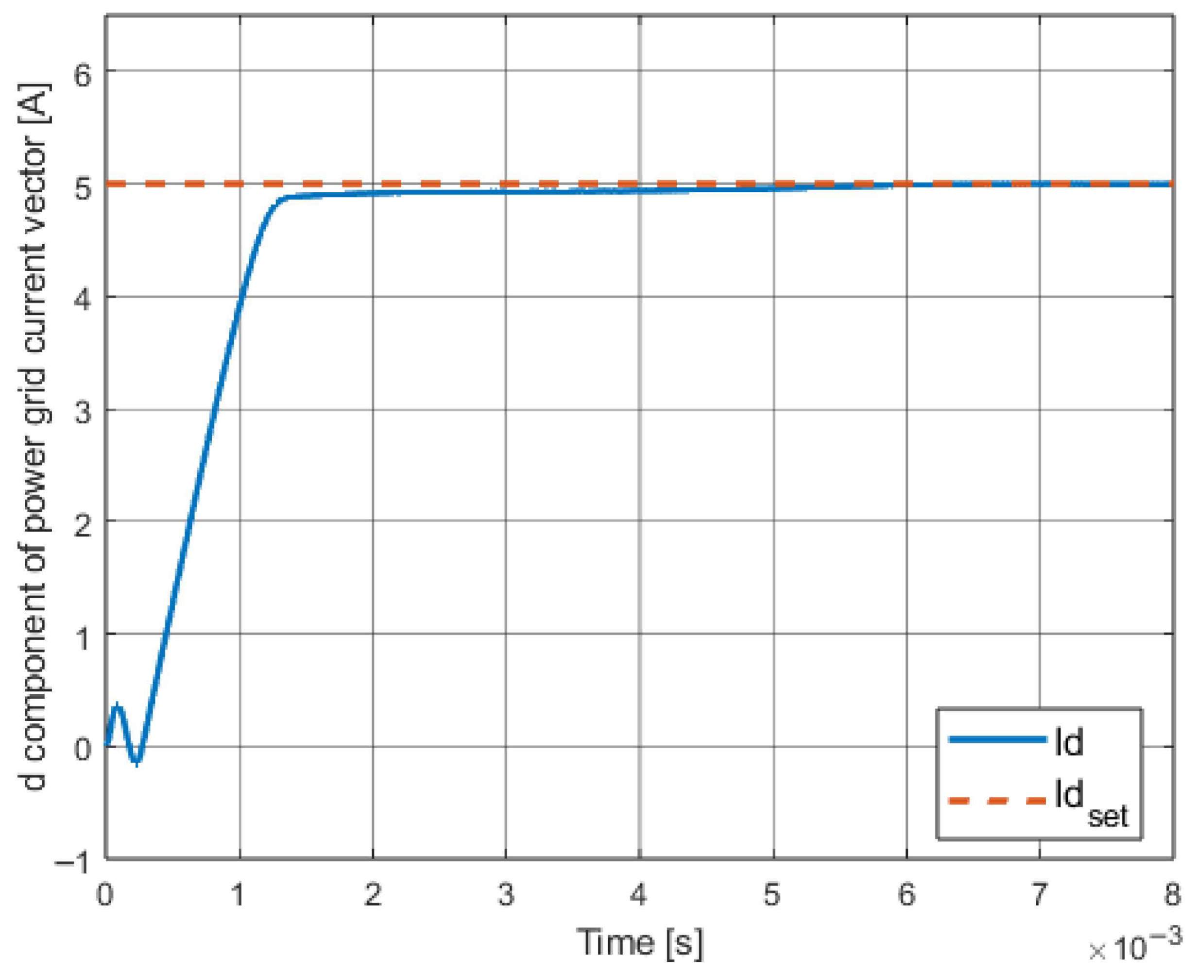
This subsection presents the simulation test results. Again, the same test scenario was used and the signal waveforms were recorded. It should also be mentioned that the lower limit of the auxiliary signal ϕ ( k ) proposed in (36) is 1 A and the upper limit is 100 A. The below presented waveforms demostrate the operation of the implemented adaptation mechanism—it may not be visible at first glance and will be more exposed through the presentation of quality measures in Section 7, but it is noticeable that the regulation time is shorter for the adaptive case in Figure 15 than for the case without the adaptation mechanism in Figure 12, which occurred without exceeding the maximum value of the control signal.
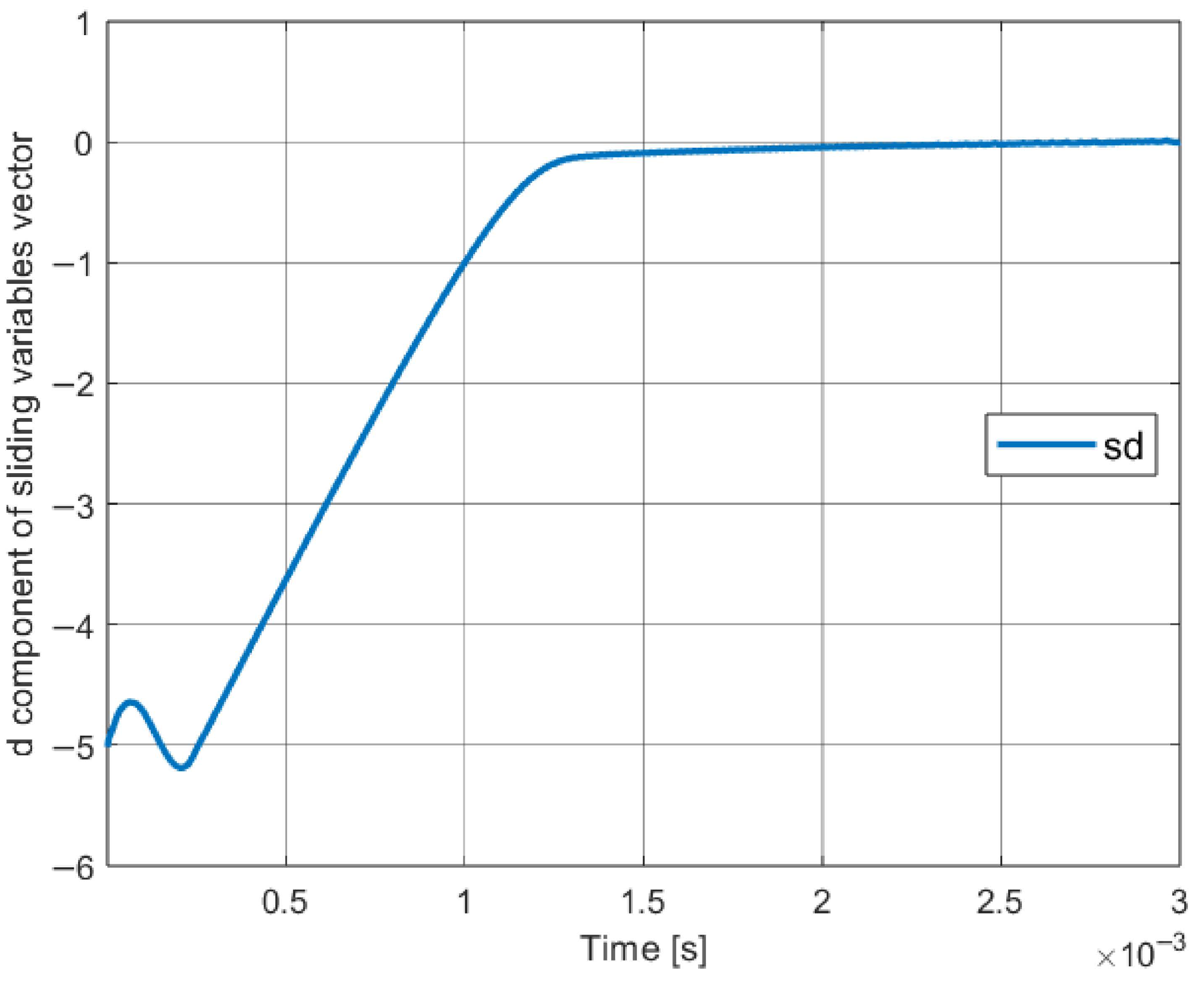
Comparing the results shown in Figure 16 to the case of using nonswitching reaching law algorithm with lack of adaptation mechanism in Figure 13, it should be mention that, in addition to the shorter reaching phase time mentioned earlier, the initial value changes (up to 0.25 milliseconds) were also reduced in terms of amplitude.

6. Introducing Steady Error Reduction Mechanism

The use of the adaptation mechanism allowed the system to adapt to various setpoint states and dynamic conditions, which significantly decreased the control time; however, one drawback still remains, which is better shown by rescaling the results from Figure 14, namely the non-zero steady-state error. This section presents the proposed concept that shall allow minimizing the steady-state error while using the discussed nonswitching reaching law type in the form with adaptation.

6.1. Description of the Proposed Method

Methods of reducing the steady-state error in the sliding-mode control theory often come down to the use of methods that take into account the calculation of the integral of the controlled quantity error or selected state variable. This element is usually included in the sliding variable [59,60,61].
In the case discussed in this paper, the topic concerns an advanced and specific control law based on the use of an appropriately limited dead-beat, therefore in the reaching phase (in the dynamic state) the reaching law should not be modified in any way by implementing an integral in the control law. Using an additional element in the sliding variable, which refers to the dead-beat coefficients through the hyperplane coefficients, is not correct due to the fact of modifying this hyperplane without referring to the dead-beat. In practice, in dynamic states the system may turn out to be unstable. Hence, the method proposed in the next subsection should only be activated interchangeably with the adaptation mechanism, i.e., adaptation operates in the dynamic state, and the steady-state error reduction is activated in the steady-state with a non-zero error presence. Such an implementation is possible because in the steady state adaptation is not crucial, and in the dynamic state the steady-state error reduction mechanism does not lead to an improvement in the quality of control, but quite the opposite.

6.2. Implementation of the Mechanism

The steady-state error reduction algorithm cooperating with the adaptive control law from Equation (37) can be described as follows, by modifying Equation (18):
s d ( k ) = c 1 [ i d ( k ) i d s e t ( k ) ] + c 2 [ u c d ( k ) u c d s e t ( k ) ] + c 3 [ i g d ( k ) i g d s e t ( k ) ] for ψ ( k ) = 0 c 1 [ i d ( k ) i d s e t ( k ) ] + c 2 [ u c d ( k ) u c d s e t ( k ) ] + c 3 [ i g d ( k ) i g d s e t ( k ) ] + γ T j = k s k [ i g d ( j ) i g d s e t ( j ) ] for ψ ( k ) = 1 ,
for which, together with the condition k 1 :
ψ ( k ) = 0 , for i g d s e t ( k ) i g d s e t ( k 1 ) ) T > i g d s e t δ m a x | s d ( k ) | 1 ψ ( k 1 ) = 1 1 , for i g d ( k ) i g d ( k 1 ) ) T < i g d δ m a x | s d ( k ) | < 1 i g d s e t ( k ) i g d s e t ( k 1 ) ) T i g d s e t δ m a x ψ ( k 1 ) = 0 ψ ( k 1 ) error
where
-
i g d s e t δ m a x —maximum permissible value of the change in the set value of the d component of the grid current vector;
-
i g d δ m a x —maximum value of the change in the d component of the grid current vector, below which it is assumed that the steady state is present;
-
γ —gain of control based on the steady-state error reduction mechanism, γ > 0 ;
-
T—sampling period ( T = 20 μ s );
-
k s —a discrete moment of time for which the activation condition of the mechanism is met;
-
ψ ( k ) —a logical variable enabling the mathematical notation of the implementation of the activation and deactivation mechanism of the steady-state error reduction algorithm; ψ ( 0 ) = 0 (mechanism disabled by default).
Considering modifications proposed in (39) and (40) it is important to mention that providing the system with a sliding variable reduction to zero shall not necessarily lead to reduction of the individual errors included in this variable - only the linear combination of these errors shall tend to zero. However, including an error reduction mechanism based on discrete integral calculation precisely for one controlled signal, which is in this case grid current vector d component, allows to achieve the expected results, i.e., to obtain a zero value of the specific error.
The following element from Equation (39):
γ T j = k s k [ i g d ( j ) i g d s e t ( j ) ] ,
is always equal to zero at the time of mechanism activation and while it is active, its value also tends to zero—right after starting to reduce the steady-state error–due to its construction based on the integral.

6.3. Obtained Results

An analogous set of results was again generated for the same test scenario, this time also incorporating the steady-state error mechanism in the control law.
The control law based on the nonswitching reaching law type from Equation (19) was extended by two mechanisms: adaptation of the key control parameter and reduction in the steady-state error.
The proposed control law described by Equations (37)–(40) allowed for the obtainment of the following effects: the short control time obtained in the case of using the adaptation mechanism alone was maintained, which was visible in Figure 15, but additionally the problem of the presence of the non-zero steady-state error, visible in Figure 14 and Figure 17, was eliminated, which, thanks to the applied method from Equation (39), ceased to be present in the grid current signal, which is visible in Figure 18 and Figure 19 (in terms of the sliding variable) and in particular in Figure 20. All the positives obtained by using the previous techniques were additionally preserved. The detailed summary of results and the summary are placed in the next section.

7. Comparative Analysis of the Presented Methods

Based on the test scenario described in Section 3.5, a series of simulation tests were performed, the results of which are visualized in the graphics from Figure 6, Figure 7, Figure 8, Figure 9, Figure 10, Figure 11, Figure 12, Figure 13, Figure 14, Figure 15, Figure 16, Figure 17, Figure 18, Figure 19 and Figure 20. Using the measured data, the following quality metrics were determined: ISE and IAE for the entire time range of the test scenario, as well as ISE, IAE, minimum and maximum error for the steady state.

7.1. Control Measures Summary

The collected data were prepared for comparison in the form of appropriate tables, which contain the values of the aforementioned quality measures assigned to the given type of control algorithm used. The steady state was defined as the state from 0.01 s to the end of the simulation duration (0.08 s). The steady state study therefore concerns 3.5 periods of the sinusoidal grid current signal.
Table 1 presents the IAE and ISE control measures for all five control methods presented in this publication. The main goal of this test scenario was to initially examine the quality of control considering the dynamic state and the steady state of a specified duration.
The results of the steady-state tests, which is the most important aspect in this work, are included in Table 2 and Table 3. The obtained results are described in detail in the next subsection.

7.2. Test Results Analysis

The use of the control algorithm based on the control law (37)–(40) resulted from an attempt to introduce a method that should lead to a significant improvement in the quality of control in the context of the dynamic state and the steady state by using a sliding hyperplane with an analytically justified form. Theoretical aspects and assumptions of this method indicated the possibility of completely reducing the impact of the chattering phenomenon on the system and obtaining a characteristic of the waveform, the specificity of which may be desired in certain control tasks in power electronics, and most importantly completely eliminates the problem of overshoot.
Based on the data from Table 1 it is possible to state that the quality of algorithms based on (19) is lower than for the classic solution and the better hybrid solution in the context of proposed control measures. This is due to the specific trajectory of the representative point in the case of using control laws based on (19), which from the perspective of calculating the values of quality measures may indeed seem less qualitative. However, its advantages should be taken into account, i.e., the previously mentioned almost linear signal growth without overshoot, for which the maximum control values resulting from the limitations of the three-phase inverter are not exceeded. Moreover, it is important to observe that the dynamic state in the control processes related to the discussed issue constitutes a significant minority of the entire process. The change of the grid current signal controlled in this way is also to a much lesser extent burdened with complications and consequences resulting from more chaotic and oscillatory, and often noisy waveforms. To discuss the most important and key advantages of the proposed control laws, it is necessary to refer first to the steady-state case.
The first issue concerning the waveforms of the grid current in the steady state is the range of oscillation values caused by the operation of electronic switches in the inverter. The use of the classic SMC from (11) additionally introduced oscillations visible in Figure 10 to the system, which was reduced using the control law from (13), obtaining the result visible in Figure 11, which was largely successful. One of the main goals of introducing the method based on the nonswitching reaching law type was to ensure an even greater reduction in the described phenomena—the nonswitching rule by definition eliminates the chattering problem, while the remaining oscillations should be reduced to an even greater extent than for (13) due to the analytically justified selection of the sliding hyperplane parameters and the control law parameters in (19). Apart from the presence of the steady-state error, visible in Figure 14, it is possible to conclude that the amplitude of the occurring unfavorable oscillations was reduced in comparison to the hybrid algorithm. The problem of the occurrence of the steady-state error was eliminated by using the laws (39)–(40), and the results presented in Table 2 confirm that the algorithm described by the quoted equations allows to narrow down the range of the amplitude of the mentioned oscillations many times more in comparison to other methods used.
The data included in Table 3 shows that the control quality in the case of using the last proposed algorithm from (37)–(40) is significantly higher than in the case of the other methods. This is due to the use of the adaptation mechanism leading to a reduction in the control time within the control constraints, but also the lack of chattering and, above all, the total disappearance in the steady-state error, which was the main disadvantage of the basic version of the algorithm from (19). Therefore, the best results were obtained for the case of the final form of the algorithm based on the nonswitching reaching law type, while maintaining the advantages concerning the shape of the characteristic in dynamic states and the narrowest range of quasi-sliding motion. These advantages are also visible when comparing results from Figure 8, Figure 9, Figure 13, Figure 16 and Figure 19—by using nonswitching reaching law control methods it is possible to ensure the system with a smooth and stiff sliding variable signal waveform that is close to linear shape in its characteristics. Two introduced algorithms provide even better results by shortening the settling time and by reducing the steady-state error to zero.

8. Conclusions

This paper presents an attempt to adapt one of the sliding-mode algorithms known in the theory of control laws to be used in a precisely modeled system representing a real case of the control problem. First, methods known from the literature that were successfully applied to the case of grid-following inverter control were presented and implemented. The results obtained by using these methods were presented, and then the advantages and disadvantages of these solutions were indicated. The next step was the introduction of a more sophisticated sliding mode control method known from the literature, which was supposed to potentially eliminate the disadvantages of the methods mentioned earlier, i.e., the lack of a full analytical approach, overshoots, oscillations, etc. It was possible to implement the nonswitching reaching law algorithm from [5] using the dead-beat sliding hyperplane parameters. For example, this algorithm allowed for the elimination of chattering and obtain a waveform shape that can be a significant advantage in many technological processes. In the next step, the disadvantages of this solution were indicated and two methods were proposed that could potentially eliminate these disadvantages: control parameter adaptation and the steady-state error reduction mechanism. These algorithms were then described and implemented, and the test results confirmed that they provide the highest quality of regulation, including the quality of energy transmitted through the grid. The two methods were also synthesized so that they could cooperate and not interfere with each other. The limitations of the system were also taken into account, as well as the potential variability of the power grid. The sliding mode control methods proposed in this paper turned out to be a very interesting extension of known methods. The control quality of the introduced algorithms was experimentally confirmed, and their advantages were discussed in detail. The possibility of implementing specific methods known in theory to practical problems, in this case related to power electronics, was confirmed. The developed methods can be also utilized in other control problems, i.e., wherever various changes in setpoints and the occurrence of a non-zero steady-state error are expected, the presence of which in real objects is often certain. The continuous development of devices, including power electronics, as well as the increasing requirements for devices, make the development of the field of control algorithms very dynamic, as mentioned in the introduction.

Author Contributions

Conceptualization, A.S., P.L. and P.C.; methodology, A.S., P.L. and P.C.; software, A.S.; validation, A.S., P.L. and P.C.; formal analysis, A.S., P.L. and P.C.; investigation, A.S.; resources, A.S.; data curation, P.L. and P.C.; writing—original draft preparation, A.S.; writing—review and editing, A.S., P.L. and P.C.; visualization, A.S.; supervision, P.L. and P.C.; project administration, P.C. All authors have read and agreed to the published version of the manuscript.

Funding

This research received no external funding.

Data Availability Statement

The data presented in this study are available on request from the corresponding author.

Conflicts of Interest

The authors declare no conflicts of interest.

Appendix A. Discrete State Matrix Elements

A d 11 = 2 L + L g e T L L g C f L L g + L g e T L L g C f L L g 2 L + L g ,
A d 12 = C f L g e T L L g C f L L g e T L L g C f L L g 2 C f L L g L + L g ,
A d 13 = 2 L g + L g e T L L g C f L L g + L g e T L L g C f L L g 2 L + L g ,
A d 21 = e T L L g C f L L g e T L L g C f L L g L + L g 2 C f L + L g ,
A d 22 = e T L L g C f L L g e T L L g C f L L g 2 ,
A d 23 = e T L L g C f L L g e T L L g C f L L g L + L g 2 C f L + L g ,
A d 31 = 2 L + L e T L L g C f L L g + L e T L L g C f L L g 2 L + L g ,
A d 32 = C f L e T L L g C f L L g e T L L g C f L L g 2 C f L L g L + L g ,
A d 33 = 2 L g + L e T L L g C f L L g + L e T L L g C f L L g 2 L + L g .

Appendix B. Modified Discrete State Matrix Elements

A d 11 δ = 2 L + L g δ e T L L g δ C f δ L L g δ + L g δ e T L L g δ C f δ L L g δ 2 L + L g δ ,
A d 12 δ = C f δ L g δ e T L L g δ C f δ L L g δ e T L L g δ C f δ L L g δ 2 C f δ L L g δ L + L g δ ,
A d 13 δ = 2 L g δ + L g δ e T L L g δ C f δ L L g δ + L g δ e T L L g δ C f δ L L g δ 2 L + L g δ ,
A d 21 δ = e T L L g δ C f δ L L g δ e T L L g δ C f δ L L g δ L + L g δ 2 C f δ L + L g δ ,
A d 22 δ = e T L L g δ C f δ L L g δ e T L L g δ C f δ L L g δ 2 ,
A d 23 δ = e T L L g δ C f δ L L g δ e T L L g δ C f δ L L g δ L + L g δ 2 C f δ L + L g δ ,
A d 31 δ = 2 L + L e T L L g δ C f δ L L g δ + L e T L L g δ C f δ L L g δ 2 L + L g δ ,
A d 32 δ = C f δ L e T L L g δ C f δ L L g δ e T L L g δ C f δ L L g δ 2 C f δ L L g δ L + L g δ ,
A d 33 δ = 2 L g δ + L e T L L g δ C f δ L L g δ + L e T L L g δ C f δ L L g δ 2 L + L g δ .

References

  1. Bartoszewicz, A. Conventional sliding modes in continuous and discrete time domains. In Proceedings of the 2017 18th International Carpathian Control Conference (ICCC), Sinaia, Romania, 28–31 May 2017; pp. 588–593. [Google Scholar]
  2. Utkin, V.; Shi, J. Integral sliding mode in systems operating under uncertainty conditions. In Proceedings of the 35th IEEE Conference on Decision and Control, Kobe, Japan, 13 December 1996; Volume 4, pp. 4591–4596. [Google Scholar]
  3. Zenteno-Torres, J.; Cieslak, J.; Dávila, J.; Henry, D. Sliding Mode Control with Application to Fault-Tolerant Control: Assessment and Open Problems. Automation 2021, 2, 1–30. [Google Scholar] [CrossRef]
  4. Latosiński, P.; Adamiak, K. Discrete-Time Sliding Mode Control Strategies—State of the Art. Energies 2024, 17, 4564. [Google Scholar] [CrossRef]
  5. Bartoszewicz, A.; Lesniewski, P. New Switching and Nonswitching Type Reaching Laws for SMC of Discrete Time Systems. IEEE Trans. Control Syst. Technol. 2016, 24, 670–677. [Google Scholar] [CrossRef]
  6. Jiang, Y.; Wang, Q.; Dong, C. A reaching law based neural network terminal sliding-mode guidance law design. In Proceedings of the 2013 IEEE International Conference of IEEE Region 10 (TENCON 2013), Xi’an, China, 22–25 October 2013; pp. 1–5. [Google Scholar]
  7. Xi, L.; Yang, S.; Dong, H.; Qi, X. Terminal Sliding Mode Control for Robotic Manipulator Based on Combined Reaching Law. In Proceedings of the 2019 International Conference on Computer Network, Electronic and Automation (ICCNEA), Xi’an, China, 27–29 September 2019; pp. 436–441. [Google Scholar]
  8. Leng, J.; Ma, C. Sliding Mode Control for PMSM Based on a Novel Hybrid Reaching Law. In Proceedings of the 2018 37th Chinese Control Conference (CCC), Wuhan, China, 25–27 July 2018; pp. 3006–3011. [Google Scholar]
  9. Sawiński, A.; Chudzik, P.; Tatar, K. Smc algorithms in t-type bidirectional power grid converter. Energies 2024, 17, 2970. [Google Scholar] [CrossRef]
  10. Szewczyk, F. Sliding Mode Control Restart Strategy for Rotating Induction Machine Using Time-Varying Switching Line. Przegląd Elektrotechniczny 2024, 1, 21–26. [Google Scholar] [CrossRef]
  11. Mozayan, S.M.; Saad, M.; Vahedi, H.; Fortin-Blanchette, H.; Soltani, M. Sliding Mode Control of PMSG Wind Turbine Based on Enhanced Exponential Reaching Law. IEEE Trans. Ind. Electron. 2016, 63, 6148–6159. [Google Scholar] [CrossRef]
  12. Sawiński, A.; Chudzik, P.; Tatar, K. Cascade Sliding Mode Control for Linear Displacement Positioning of a Quadrotor. Sensors 2025, 25, 883. [Google Scholar] [CrossRef] [PubMed]
  13. Rajanna, G.S.; Nagaraj, H.N. Comparison between sigmoid variable reaching law and exponential reaching law for sliding mode controlled DC-DC Buck converter. In Proceedings of the 2013 International Conference on Power, Energy and Control (ICPEC), Dindigul, India, 6–8 February 2013; pp. 316–319. [Google Scholar]
  14. Latosinski, P.; Bartoszewicz, A.; Lesniewski, P. A new reaching law based DSMC for inventory management systems. In Proceedings of the 2017 21st International Conference on System Theory, Control and Computing (ICSTCC), Sinaia, Romania, 19–21 October 2017; pp. 372–377. [Google Scholar]
  15. Bartoszewicz, A.; Lesniewski, P. Non-switching type reaching law with application to congestion control in connection-oriented communication networks. In Proceedings of the 2014 European Control Conference (ECC), Strasbourg, France, 24–27 June 2014; pp. 1211–1216. [Google Scholar]
  16. Bartoszewicz, A.; Maciejewski, M. Dead-beat sliding mode control of perishable inventories with transportation losses and multiple suppliers. In Proceedings of the 2013 European Control Conference (ECC), Zurich, Switzerland, 17–19 July 2013; pp. 3209–3215. [Google Scholar]
  17. Ignaciuk, P.; Bartoszewicz, A. Sliding Mode Dead-Beat Control of Perishable Inventory Systems With Multiple Suppliers. IEEE Trans. Autom. Sci. Eng. 2012, 9, 418–423. [Google Scholar] [CrossRef]
  18. Nicola, M.; Nicola, C.-L. Improved Performance in the Control of DC-DC Three-Phase Power Electronic Converter Using Fractional-Order SMC and Synergetic Controllers and RL-TD3 Agent. Fractal Fract. 2022, 6, 729. [Google Scholar] [CrossRef]
  19. Bouguerra, Z. Comparative study between PI, FLC, SMC and Fuzzy sliding mode controllers of DFIG wind turbine. J. Renew. Energies 2023, 26, 209–223. [Google Scholar] [CrossRef]
  20. Kalvinathan, V.; Chitra, S. Power Optimization in Hybrid Renewable Energy Standalone System using SMC-ANFIS. Adv. Electr. Comput. Eng. 2022, 22, 69–78. [Google Scholar] [CrossRef]
  21. Liu, S.; Liu, X.; Jiang, S.; Zhao, Z.; Wang, N.; Liang, X.; Zhang, M.; Wang, L. Application of an Improved STSMC Method to the Bidirectional DC–DC Converter in Photovoltaic DC Microgrid. Energies 2022, 15, 1636. [Google Scholar] [CrossRef]
  22. Kumar, N.; Saha, T.K.; Dey, J. Design and analysis of a double band hysteresis SMC for cascaded inverter-based PV system. In Proceedings of the 2016 IEEE Region 10 Conference (TENCON), Singapore, 22–25 November 2016; pp. 898–902. [Google Scholar]
  23. Lyu, S.; Zheng, L.; Song, J.; Liu, Z.; Tian, M. A Repetitive Sliding Mode Control for Household Mircogrid Inverter Operating in Islanding Mode. In Proceedings of the 2018 IEEE International Power Electronics and Application Conference and Exposition (PEAC), Shenzhen, China, 4–7 November 2018; pp. 1–6. [Google Scholar]
  24. Zheng, W.; Li, S.; Wang, J.; Wang, Z. Sliding-mode control for three-phase PWM inverter via harmonic disturbance observer. In Proceedings of the 2015 34th Chinese Control Conference (CCC), Hangzhou, China, 28–30 July 2015; pp. 7988–7993. [Google Scholar]
  25. Bouzid, A.M.; Guerrero, J.M.; Cheriti, A.; Bouhamida, M.; Sicard, P.; Benghanem, M. A survey on control of electric power distributed generation systems for microgrid applications. Renew. Sustain. Energy Rev. 2015, 44, 751–766. [Google Scholar] [CrossRef]
  26. Rocabert, J.; Luna, A.; Blaabjerg, F.; Rodríguez, P. Control of Power Converters in AC Microgrids. IEEE Trans. Power Electron. 2012, 27, 4734–4749. [Google Scholar] [CrossRef]
  27. Gong, X.; Wang, X. A novel Koopman-inspired method for the secondary control of microgrids with grid-forming and grid-following sources. Appl. Energy 2023, 333, 120631. [Google Scholar] [CrossRef]
  28. Guo, W.; Mu, L. Control principles of micro-source inverters used in microgrid. Prot. Control Mod. Power Syst. 2016, 1, 5. [Google Scholar] [CrossRef]
  29. Mohiuddin, S.M.; Qi, J. A Unified Droop-Free Distributed Secondary Control for Grid-Following and Grid-Forming Inverters in AC Microgrids. In Proceedings of the 2020 IEEE Power & Energy Society General Meeting (PESGM), Montreal, QC, Canada, 2–6 August 2020; pp. 1–5. [Google Scholar]
  30. Hao, X.; Yang, X.; Xie, R.; Huang, L.; Liu, T.; Li, Y. A fixed switching frequency integral resonant sliding mode controller for three-phase grid-connected photovoltaic inverter with lcl-filter. In Proceedings of the 2013 IEEE ECCE Asia Downunder, Melbourne, VIC, Australia, 3–6 June 2013; pp. 793–798. [Google Scholar]
  31. Monica, P.; Kowsalya, M.; Subramanian, K. Droop reference based decoupling coupling control of NPC inverter for islanded microgrid. In Proceedings of the 2017 Innovations in Power and Advanced Computing Technologies (i-PACT), Vellore, India, 21–22 April 2017; pp. 1–5. [Google Scholar]
  32. Rąbkowski, J.; Kopacz, R. Extended T-type Inverter. Power Electron. Drives 2018, 3, 55–64. [Google Scholar] [CrossRef]
  33. Meenakshi, V.; Kavitha, M.; Antony, A.S.M.; Kaveri, V.V.; Radhika, S.; Immanuel, D.G. T-Type Three Phase Inverter with Grid Connected System used in Renewable Energy Resources. In Proceedings of the 2023 International Conference on Sustainable Computing and Data Communication Systems (ICSCDS), Erode, India, 23–25 March 2023; pp. 929–936. [Google Scholar]
  34. Gao, X.; Zhou, D.; Anvari-Moghaddam, A.; Blaabjerg, F. Stability Analysis of Grid-Following and Grid-Forming Converters Based on State-Space Modelling. IEEE Trans. Ind. Appl. 2024, 60, 4910–4920. [Google Scholar] [CrossRef]
  35. Babu, V.; Roselyn, P.; Chinnaiyan, N.; Sundaravadivel, P. Development of Grid-Forming and Grid-Following Inverter Control in Microgrid Network Ensuring Grid Stability and Frequency Response. Electronics 2024, 13, 1958. [Google Scholar] [CrossRef]
  36. Fu, X.; Sun, J.; Huang, M.; Tian, Z.; Yan, H.; Iu, H.H.; Hu, P.; Zha, X. Large-Signal Stability of Grid-Forming and Grid-Following Controls in Voltage Source Converter: A Comparative Study. IEEE Trans. Power Electron. 2021, 36, 7832–7840. [Google Scholar] [CrossRef]
  37. Du, W.; Tuffner, F.K.; Schneider, K.P.; Lasseter, R.H.; Xie, J.; Chen, Z.; Bhattarai, B. Modeling of Grid-Forming and Grid-Following Inverters for Dynamic Simulation of Large-Scale Distribution Systems. IEEE Trans. Power Deliv. 2021, 36, 2035–2045. [Google Scholar] [CrossRef]
  38. Jasim, A.; Jasim, B. Grid-forming and grid-following based microgrid inverters control. Iraqi J. Electr. Electron. Eng. 2022, 18, 111–131. [Google Scholar] [CrossRef]
  39. Sadeque, F.; Sharma, D.; Mirafzal, B. Power-Sharing between Grid-Forming and Grid-Following Inverters. In Proceedings of the 2021 IEEE 22nd Workshop on Control and Modelling of Power Electronics (COMPEL), Cartagena, Colombia, 2–5 November 2021; pp. 1–5. [Google Scholar]
  40. Gluščević, J.; Janda, Ž.; Dragosavac, J.; Ristić, L. Enhancing Stability of Grid-Following Inverter for Renewables. In Proceedings of the 2023 22nd International Symposium on Power Electronics (Ee), Novi Sad, Serbia, 25–28 October 2023; pp. 1–6. [Google Scholar]
  41. Hasan, M.M.; Chowdhury, A.H. Performance Analysis of a DQ0 Controlled Grid Forming Inverter for Grid Connected Photovoltaic System: A Case Study. In Proceedings of the 2022 4th International Conference on Sustainable Technologies for Industry 4.0 (STI), Dhaka, Bangladesh, 17–18 December 2022; pp. 1–6. [Google Scholar]
  42. Li, S.; Zhou, S.; Li, H. Harmonic Suppression Strategy of LCL Grid-Connected PV Inverter Based on Adaptive QPR_pc Control. Electronics 2023, 1, 2282. [Google Scholar] [CrossRef]
  43. Huang, J.; Zhao, Y.; Wang, J.; Zhang, P. A Hybrid Active Damping Strategy for Improving the Adaptability of LCL Converter in Weak Grid. Electronics 2023, 13, 144. [Google Scholar] [CrossRef]
  44. Ahsan, E.E.; Shobug, M.A.; Tanim, M.M.H.; Reza, M.H. Harmonic Distortion Reduction of Transformerless Inverter’s Output Voltage Using 5-Level Single-Phase Inverter and LCL Filter. In Proceedings of the 2020 2nd International Conference on Advanced Information and Communication Technology (ICAICT), Dhaka, Bangladesh, 28–29 November 2020; pp. 251–256. [Google Scholar]
  45. Choi, W.; Lee, W.; Sarlioglu, B. Effect of grid inductance on grid current quality of parallel grid-connected inverter system with output LCL filter and closed-loop control. In Proceedings of the 2016 IEEE Applied Power Electronics Conference and Exposition (APEC), Long Beach, CA, USA, 20–24 March 2016; pp. 2679–2686. [Google Scholar]
  46. Wang, B.; Zhang, X.; Song, C.; Cao, R. Research on the Filters for Dual-Inverter Fed Open-End Winding Transformer Topology in Photovoltaic Grid-Tied Applications. Energies 2019, 12, 2338. [Google Scholar] [CrossRef]
  47. Dehghani, M.; Mardaneh, M.; Shafiei, M.H. Sliding mode control for load harmonics compensation and PV voltage regulation in a grid-tied inverter through a single-stage MPPT. In Proceedings of the 2020 28th Iranian Conference on Electrical Engineering (ICEE), Tabriz, Iran, 4–6 August 2020; pp. 1–6. [Google Scholar]
  48. de Brito, M.A.G.; Junior, L.G.; Canesin, C.A. Three-phase tri-state integrated boost inverter with special space vector and dq0 control. In Proceedings of the International Symposium on Power Electronics Power Electronics, Electrical Drives, Automation and Motion, Sorrento, Italy, 20–22 June 2012; pp. 644–648. [Google Scholar]
  49. Schonardie, M.F.; Coelho, R.F.; Schweitzer, R.; Martins, D.C. Control of the active and reactive power using dq0 transformation in a three-phase grid-connected pv system. In Proceedings of the 2012 IEEE International Symposium on Industrial Electronics, Hangzhou, China, 28–31 May 2012. [Google Scholar]
  50. Schonardie, M.F.; Ruseler, A.; Coelho, R.F.; Martins, D.C. Three-phase grid-connected pv system with active and reactive power control using dq0 transformation. In Proceedings of the 2010 9th IEEE/IAS International Conference on Industry Applications—INDUSCON 2010, Sao Paulo, Brazil, 8–10 November 2010; pp. 1–6. [Google Scholar]
  51. Vinoliney, A.; Lydia, M.; Levron, Y. Optimal grid integration of renewable energy sources with energy storage using dq0 based inverter controller. In Proceedings of the 2020 International Conference on Inventive Computation Technologies (ICICT), Coimbatore, India, 26–28 February 2020; pp. 966–972. [Google Scholar]
  52. Kumar, N.; Buwa, O. A Review on Reactive Power Compensation of Distributed Energy System. In Proceedings of the 2020 7th International Conference on Smart Structures and Systems (ICSSS), Chennai, India, 23–24 July 2020; pp. 1–6. [Google Scholar]
  53. Lesniewski, P. Discrete time reaching law based sliding mode control: A survey. In Proceedings of the 2018 22nd International Conference on System Theory, Control and Computing (ICSTCC), Sinaia, Romania, 10–12 October 2018; pp. 734–739. [Google Scholar]
  54. Li, Y.; Liu, L. The research of the sliding mode control method based on improved double reaching law. In Proceedings of the 2018 Chinese Control And Decision Conference (CCDC), Shenyang, China, 9–11 June 2018; pp. 672–675. [Google Scholar]
  55. Bartoszewicz, A.; Lesniewski, P. New reaching law for quasi-sliding mode control of discrete time systems. In Proceedings of the 52nd IEEE Conference on Decision and Control, Firenze, Italy, 10–13 December 2013; pp. 2881–2887. [Google Scholar]
  56. Bartoszewicz, A. A new reaching law for sliding mode control of continuous time systems with constraints. Trans. Inst. Meas. Control 2015, 37, 515–521. [Google Scholar] [CrossRef]
  57. Bartoszewicz, A.; Lesniewski, P. Reaching Law Approach to the Sliding Mode Control of Periodic Review Inventory Systems. IEEE Trans. Autom. Sci. Eng. 2014, 11, 810–817. [Google Scholar] [CrossRef]
  58. Tatar, K.; Chudzik, P.; Leśniewski, P. Sliding mode control of buck dc–dc converter with lc input filter. Energies 2023, 16, 6983. [Google Scholar] [CrossRef]
  59. Drazenovic, B.; Milosavljevic, C.; Veselic, B. Discrete-time chattering-free integral sliding mode control of continuous-time descriptor systems. In Proceedings of the 2014 13th International Workshop on Variable Structure Systems (VSS), Nantes, France, 29 June–2 July 2014; pp. 1–6. [Google Scholar]
  60. Veselic, B.; Perunicic-Drazenovic, B.; Milosavljevic, C. Integral Sliding Manifold Design for Linear Systems With Additive Unmatched Disturbances. IEEE Trans. Autom. Control 2016, 61, 2544–2549. [Google Scholar] [CrossRef]
  61. Veselic, B.; Drazenovic, B.; Milosavljevic, C. Optimal discrete-time integral sliding manifold design for linear systems subjected to a class of unmatched disturbances. In Proceedings of the 2015 International Workshop on Recent Advances in Sliding Modes (RASM), Istanbul, Turkey, 9–11 April 2015; pp. 1–6. [Google Scholar]
Figure 1. Microgrid system simplified scheme.
Energies 18 04696 g001
Figure 2. T-type inverter topology scheme. The individual phases are marked with the letters a, b, and c.
Energies 18 04696 g002
Figure 3. A three-phase simplified model diagram.
Energies 18 04696 g003
Figure 4. Scheme of the model transformed using dq0 method.
Energies 18 04696 g004
Figure 5. Graphical representation of sliding coefficient stability for c 3 = 1 .
Energies 18 04696 g005
Figure 6. Grid current and its desired value waveforms for the d component. Classic SMC approach implementation used.
Energies 18 04696 g006
Figure 7. Grid current and its desired value waveforms for the d component. Hybrid SMC approach implementation used.
Energies 18 04696 g007
Figure 8. Sliding variable waveform for the d component. Classic SMC approach implementation used.
Energies 18 04696 g008
Figure 9. Sliding variable waveform for the d component. Hybrid SMC approach implementation used.
Energies 18 04696 g009
Figure 10. Grid current and its desired value waveforms for the d component. Classic SMC approach implementation used.
Energies 18 04696 g010
Figure 11. Grid current and its desired value waveforms for the d component. Hybrid SMC approach implementation used.
Energies 18 04696 g011
Figure 12. Grid current and its desired value waveforms for the d component. Nonswitching reaching law approach implementation used.
Energies 18 04696 g012
Figure 13. Sliding variable waveform for the d component. Nonswitching reaching law approach implementation used.
Energies 18 04696 g013
Figure 14. Grid current and its desired value waveforms for the d component. Nonswitching reaching law approach implementation used.
Energies 18 04696 g014
Figure 15. Grid current and its desired value waveforms for the d component. Adaptive nonswitching reaching law approach implementation used.
Energies 18 04696 g015
Figure 16. Sliding variable waveform for the d component. Adaptive nonswitching reaching law approach implementation used.
Energies 18 04696 g016
Figure 17. Grid current and its desired value waveforms for the d component. Adaptive nonswitching reaching law approach implementation used.
Energies 18 04696 g017
Figure 18. Grid current and its desired value waveforms for the d component. Adaptive integral nonswitching reaching law approach implementation used.
Energies 18 04696 g018
Figure 19. Sliding variable waveform for the d component. Adaptive integral nonswitching reaching law approach implementation used.
Energies 18 04696 g019
Figure 20. Grid current and its desired value waveforms for the d component. Adaptive integral nonswitching reaching law approach implementation used.
Energies 18 04696 g020
Table 1. ISE and IAE control measures summary.
Control MethodISEIAE
Classic SMC3.6939 ×   10 3 6.2885 ×   10 3
Hybrid SMC3.5924 ×   10 3 3.7845 ×   10 3
Nonswitching Reaching Law (NRL)2.2296 ×   10 2 1.3434 ×   10 2
Adaptive Nonswitching Reaching Law (ANRL)1.4890 ×   10 2 1.1379 ×   10 2
Adaptive Integral Nonswitching Reaching Law (AINRL)1.4157 ×   10 2 4.2585 ×   10 3
Table 2. Minimum and maximum error values summary.
Control MethodMIN (Steady-State)MAX (Steady-State)
Classic SMC−2.2278 ×   10 1 2.0677 ×   10 1
Hybrid SMC−4.0321 ×   10 2 6.1065 ×   10 2
NRL9.8367 ×   10 2 1.1198 ×   10 1
ANRL9.1041 ×   10 2 1.0353 ×   10 1
AINRL−6.6823 ×   10 3 8.4445 ×   10 3
Table 3. ISE and IAE control measures summary for steady-state case.
Control MethodISE (Steady-State)IAE (Steady-State)
Classic SMC4.0190 ×   10 4 4.3989 ×   10 3
Hybrid SMC6.1030 ×   10 5 1.8120 ×   10 3
NRL7.6287 ×   10 4 7.3035 ×   10 3
ANRL6.5887 ×   10 4 6.7884 ×   10 3
AINRL1.3919 ×   10 6 2.7554 ×   10 4
Disclaimer/Publisher’s Note: The statements, opinions and data contained in all publications are solely those of the individual author(s) and contributor(s) and not of MDPI and/or the editor(s). MDPI and/or the editor(s) disclaim responsibility for any injury to people or property resulting from any ideas, methods, instructions or products referred to in the content.