Abstract
In this study, a high-efficiency permanent magnet synchronous motor (PMSM) was designed for a geared electric vehicle. The motor was developed for use in an L-category electric vehicle with four wheels and a two-passenger capacity. During the design process, application-specific dimensional constraints, electromagnetic requirements, and material limitations were taken into consideration. A spoke-type rotor structure was adopted to achieve both mechanical robustness and high efficiency with minimized leakage flux. In addition, the combination of a 12-stator slot and a 10-rotor pole was selected to suppress low-order harmonic components and improve torque smoothness. The motor model was analyzed using Siemens Simcenter SPEED software (Product Version 2020.3.1), and an efficiency above 94% was achieved, meeting the IE6 efficiency class. Magnetic flux analysis results showed that the selected core material operated within the magnetic saturation limits. The findings demonstrate that a compact and high-efficiency PMSM design is feasible for electric vehicle applications.
1. Introduction
The rapid development of electric vehicle (EV) technologies has been driven by the urgent need to reduce greenhouse gas emissions and improve energy efficiency in the transportation sector. This transition is further accelerated by regulations that are increasingly geared towards environmental factors, such as the European Union’s CO2 emission targets and the global adoption of higher efficiency standards for electric drive systems [1,2,3,4]. As the electrification of transportation continues to expand, the traction motor has emerged as a critical component influencing vehicle performance, energy consumption, and operational range. Consequently, the design and optimization of traction motors have become a central research focus in the industry.
Electric traction motors for EV applications must satisfy multiple and often conflicting design requirements, including high efficiency across a wide operating range, a compact size to fit within constrained chassis geometries, and sufficient thermal robustness to ensure reliability under continuous load [5]. Permanent magnet synchronous motors (PMSMs) have become the preferred choice for many EV manufacturers due to their high efficiency, high torque density, and wide constant power speed range compared to induction machines or switched reluctance motors [6,7,8,9]. Within this category, interior permanent magnet synchronous motors (IPMSMs) offer further advantages through rotor configurations such as spoke-type or V-shaped topologies, which enhance flux focusing, improve torque output, and extend flux-weakening capability [10].
Over the past decade, numerous studies have investigated PMSM and IPMSM designs for traction applications, focusing on aspects such as rotor topology optimization [11,12,13], fractional-slot concentrated windings [14,15,16], and advanced cooling strategies [17,18,19]. Spoke-type PMSM configurations, in particular, have been shown to reduce torque ripple and suppress harmonics [20], while fractional-slot concentrated windings can decrease copper loss through shorter end-turns and improve the slot fill factor [21]. Moreover, the integration of finite element analysis (FEA) with analytical modeling has enabled multi-objective optimization simultaneously targeting efficiency, torque density, and manufacturability. Recent advances in computational tools have also enabled more accurate prediction of iron losses, magnet demagnetization risk, and thermal behavior, further extending the applicability of simulation-based design approaches. Despite these advancements, several technical gaps remain unaddressed.
High-efficiency PMSMs have been successfully developed for industrial applications, but these machines typically employ larger frame sizes or active cooling systems that are impractical for compact EV applications. PMSM designs for EV applications often aim to achieve high efficiency while also meeting strict constraints on size, weight, and integration within limited space. Various PMSM designs targeting EV applications place primary emphasis on specific technical features, such as harmonic mitigation or flux-weakening capability [22], while offering limited benchmarking of overall efficiency relative to other high-performance machines. However, adapting such designs to the compact packaging requirements of EVs often demands a re-evaluation of rotor geometry, cooling methods, and material selection, which introduces additional multidisciplinary challenges. This underscores the importance of broader performance comparisons to assess the practical applicability of such designs in real-world EV scenarios.
In addition to electromagnetic performance, mechanical robustness and manufacturability are also key considerations in the design of PMSMs for EV applications. Spatial constraints in specific vehicles, such as L-category urban EVs, impose further design challenges. Motors for these applications must deliver high torque density within a limited envelope while ensuring manufacturability and cost-effectiveness. Reports in the literature describing PMSM designs that meet such spatial limitations while simultaneously achieving high efficiency remain limited. Existing industrial high-efficiency machines often cannot be directly adapted due to their larger frame sizes, active cooling requirements, or incompatible mounting configurations. This combination of requirements (compactness, high efficiency, and the potential for passive cooling) thus defines a clear gap in the current state of the art. In particular, there is a lack of studies that explicitly address the simultaneous optimization of slot/pole number selection, spoke-type rotor topology, and winding design under the dimensional and operational constraints of L-category EVs. While achieving high efficiency and torque density is a general requirement across traction motor designs, the present study addresses this gap by combining these requirements with the strict packaging limitations and manufacturability constraints of L-category EVs.
The present study focuses on the design and analysis of a 12-slot/10-pole spoke-type PMSM optimized for electric vehicle applications with geared transmission systems. The primary objectives are to achieve high efficiency consistent with IE6 efficiency classification targets, maintain a compact geometry suitable for limited installation spaces, and ensure smooth torque output through appropriate rotor topology selection. The design process combines analytical pre-design calculations with detailed finite element method (FEM) simulations to refine the electromagnetic parameters, evaluate torque and efficiency characteristics, and estimate the associated loss components. The proposed approach aims to provide a balanced solution that addresses both performance and manufacturability requirements, offering practical insights for the development of high-efficiency traction motors in next-generation electric vehicles.
In summary, the key contributions of this work are
- (1)
- The design of a high-efficiency spoke-type PMSM optimized for the dimensional constraints and operational requirements of L-category electric vehicles;
- (2)
- Demonstrating high torque density and low torque ripple within restricted installation spaces;
- (3)
- Providing a simulation-based design framework for evaluating electromagnetic performance, torque production, and loss distribution in compact traction motor applications.
2. Materials and Methods
In this study, a high-efficiency permanent magnet synchronous motor was designed for an electric vehicle with a geared transmission system. Within the design process, both electromagnetic and mechanical criteria were considered to size the motor, select appropriate materials, and analyze its conformity to performance targets and operating conditions. The design criteria and characteristics of the proposed motor are presented in this section.
2.1. Design Requirements
The PMSM is designed specifically for the traction requirements of L-category electric vehicles, which are compact urban mobility solutions typically intended for two passengers. These vehicles are characterized by their lightweight structure, limited installation space, and modest speed range, making them well-suited for short-range city commuting. In this context, the motor must deliver high torque at low speeds to ensure sufficient acceleration in urban driving conditions, while simultaneously maintaining high efficiency to maximize vehicle range within the limited battery capacity.
The proposed machine is designed to operate with a geared transmission system, enabling an effective balance between torque generation and vehicle speed. Through the integration with a single-speed gearbox, the motor’s shaft power is efficiently transferred to the wheels, ensuring the high starting torque required in stop-and-go traffic, while also providing smooth operation at the rated top speed of the vehicle. This configuration enhances driving comfort, reduces energy losses, and ensures compatibility with the overall dynamics of compact EV drivetrains.
Moreover, the design requirements place particular emphasis on compactness, manufacturability, and cost-effectiveness. Given the limited chassis space of L-category EVs, the motor geometry must be carefully optimized to achieve high torque density within a restricted envelope. At the same time, thermal robustness is essential, since the compact design reduces the possibility of employing large active cooling systems. Therefore, the proposed design aims to ensure reliable operation under natural or simplified forced-air cooling, consistent with the practical constraints of lightweight urban vehicles.
Table 1 summarizes the key technical specifications of the selected reference vehicle, which guided the definition of motor power, torque, and operational parameters in the design process.

Table 1.
Technical specifications of the electric vehicle.
2.2. Design of the PMSM
In the motor design process, the outer diameter of the stator was determined to be 144 mm, considering the available mounting space within the vehicle. A 12-stator-slot and 10-rotor-pole configuration was selected to achieve high efficiency, compact structure, and low harmonics. The selection of a 12-slot/10-pole spoke-type PMSM topology was motivated by its favorable electromagnetic performance characteristics, including high torque density, wide constant-power speed range, and the inherent potential for low torque ripple. While this combination has been reported in previous studies, its direct adaptation to the spatial and operational constraints of L-category electric vehicles presents unique engineering challenges. The compact chassis configuration of such vehicles imposes strict limitations on the motor’s axial length and overall envelope, while also restricting the integration of active cooling systems. To address these constraints, the rotor geometry, stator slot design, and winding configuration were tailored to achieve the required torque output and efficiency targets within the restricted installation space. The spoke-type rotor layout was specifically optimized to suppress low-order harmonics, ensuring smooth torque delivery without the need for additional structural complexity. Analytical pre-design calculations provided the initial dimensions and electromagnetic loading estimates, which were then refined through high-fidelity finite element analysis to evaluate the effects of magnet placement, flux concentration, and tooth geometry on torque ripple, efficiency, and manufacturability. Special attention was given to the winding end-turn length to improve the slot fill factor and minimize copper losses, which is critical in compact designs where space efficiency directly impacts performance. This engineering adaptation demonstrates that the 12-slot/10-pole spoke-type topology, when systematically optimized for compact EV constraints, can simultaneously satisfy high efficiency, favorable torque per volume ratio, and manufacturability requirements without active cooling. The approach bridges the gap between theoretically optimal electromagnetic designs and practical implementation in space-limited traction applications.
The electromagnetic and geometric considerations, the material selection for both the stator/rotor cores and the permanent magnets is a decisive factor in achieving the targeted performance objectives. The materials employed in the designed PMSM are summarized in Table 2. The magnetic cores of both the stator and rotor are composed of M250-50A non-oriented electrical steel laminations. This grade was selected due to its favorable compromise between magnetic permeability and specific core losses under the design operating frequency. Its relatively low hysteresis and eddy current losses contributed to the efficiency requirements of the machine while maintaining manufacturability and cost-effectiveness. Furthermore, the use of M250-50A allowed sufficient magnetic flux conduction capacity without pushing the laminations into premature saturation, which is a crucial concern for compact traction motors where high flux densities are concentrated in a confined volume. For the rotor permanent magnets, NdFeB grade N30SH was selected. NdFeB alloys are widely recognized for their superior remanence and coercivity compared to ferrite or SmCo alternatives, making them particularly suitable for high-torque-density traction motors. The N30SH grade, with a remanence flux density (Br) on the order of 1.05–1.10 T, combines strong magnetic properties with enhanced thermal stability. The “SH” classification corresponds to a maximum operating temperature of approximately 150 °C, which significantly reduces the risk of irreversible demagnetization during continuous traction operation in compact electric vehicle environments. This high-temperature capability was considered essential for the intended geared EV application, as forced cooling options are limited in the restricted chassis layout. The spoke-type rotor was designed with rectangular NdFeB permanent magnets having dimensions of 27 mm (axial length) × 16 mm (width) × 3.8 mm (height/thickness) for each insert. This corresponds to a per magnet volume of approximately 1641.6 mm3 (≈1.64 cm3). The relatively small thickness of 3.8 mm was selected to support flux focusing and reduce leakage across the rotor bridges, while the 16 mm width ensured adequate radial flux interaction with the stator teeth. The length of 27 mm was matched to the active stack height of the motor, thereby maximizing the effective utilization of the magnet volume in the electromagnetic design. The selected geometry was finalized after iterative evaluation of flux distribution, torque density, and manufacturability, ensuring that both electromagnetic and mechanical requirements were satisfied within the restricted motor envelope. This magnet configuration was determined through a parametric design process, in which variations in insertion depth and tangential span were evaluated to balance torque density, efficiency, and manufacturability under the geometric restrictions of L-category electric vehicles. Particular attention was given to avoiding local saturation in the stator teeth and rotor bridges, as well as to mitigating mechanical stress concentrations around the magnet cavities. The adopted geometry reflects a compromise between electromagnetic performance and structural robustness, ensuring reliable operation in continuous duty.

Table 2.
Materials of the designed PMSM.
The motor designed with this configuration is targeted to achieve an efficiency level exceeding 94%. This objective aligns with the IE6 efficiency class discussed in the draft version of IEC 60034-30-3 [23], which, although not yet officially standardized, has been proposed in the literature. The IE6 class aims to reduce motor losses by approximately 20% compared to the currently highest standardized efficiency class, IE5 [24]. Thanks to the reduced losses in the motor, the resulting thermal load within the system will be significantly decreased, eliminating the need for an active cooling system. Since the motor is planned to be mounted at the front of the electric vehicle, it is intended to utilize natural airflow for passive cooling during operation. Accordingly, the motor has been designed with a structure featuring only two end covers, allowing direct contact between the internal components and the air. As there is no specific requirement for a protection class in this application, the motor was designed with an IP0 protection level, and ventilation holes were added to the front and rear covers to promote air circulation. This configuration enables effective heat dissipation and eliminates the need for additional active cooling systems, ensuring that the thermal assumptions used in the analyses are consistent with the real installation environment.
2.3. Design Constraints
The design process of an electric motor is shaped by constraints arising from both the physical installation space and the selected materials. Dimensional parameters, such as the stator outer diameter and core length, are generally limited by the available mounting space within the application environment. In this study, the overall motor envelope was constrained to 150 × 150 × 54 mm (W × H × L), corresponding to a total volume of 1.215 × 10⁻³ m3 (≈1.2 L). This compact envelope was dictated by the installation requirements of the target vehicle. Additionally, constraints related to materials and performance stem from factors such as the motor’s thermal endurance and magnetic properties. In this context, design parameters including torque per rotor volume (TRV), electrical loading (Ac), the ratio of inner to outer diameter (Dsi/Dso), the aspect ratio (Lstk/Dsi), supply voltage, and current density (Jrms) are taken into consideration. These parameters define the design boundaries while ensuring optimal performance within the physical and material limitations of the motor, as well as compatibility with application-specific requirements.
2.4. Outputs of PMSM
The motor model was developed in accordance with the specific application requirements and the constraints imposed by the selected materials. To maintain the clarity and conciseness of this paper, detailed analytical and numerical calculations involved in the design process have been omitted. Instead, the key design parameters are summarized in Table 3. For a comprehensive explanation of the design methodology and the underlying computational procedures, readers are referred to [25,26,27].

Table 3.
Design parameters of the proposed motor.
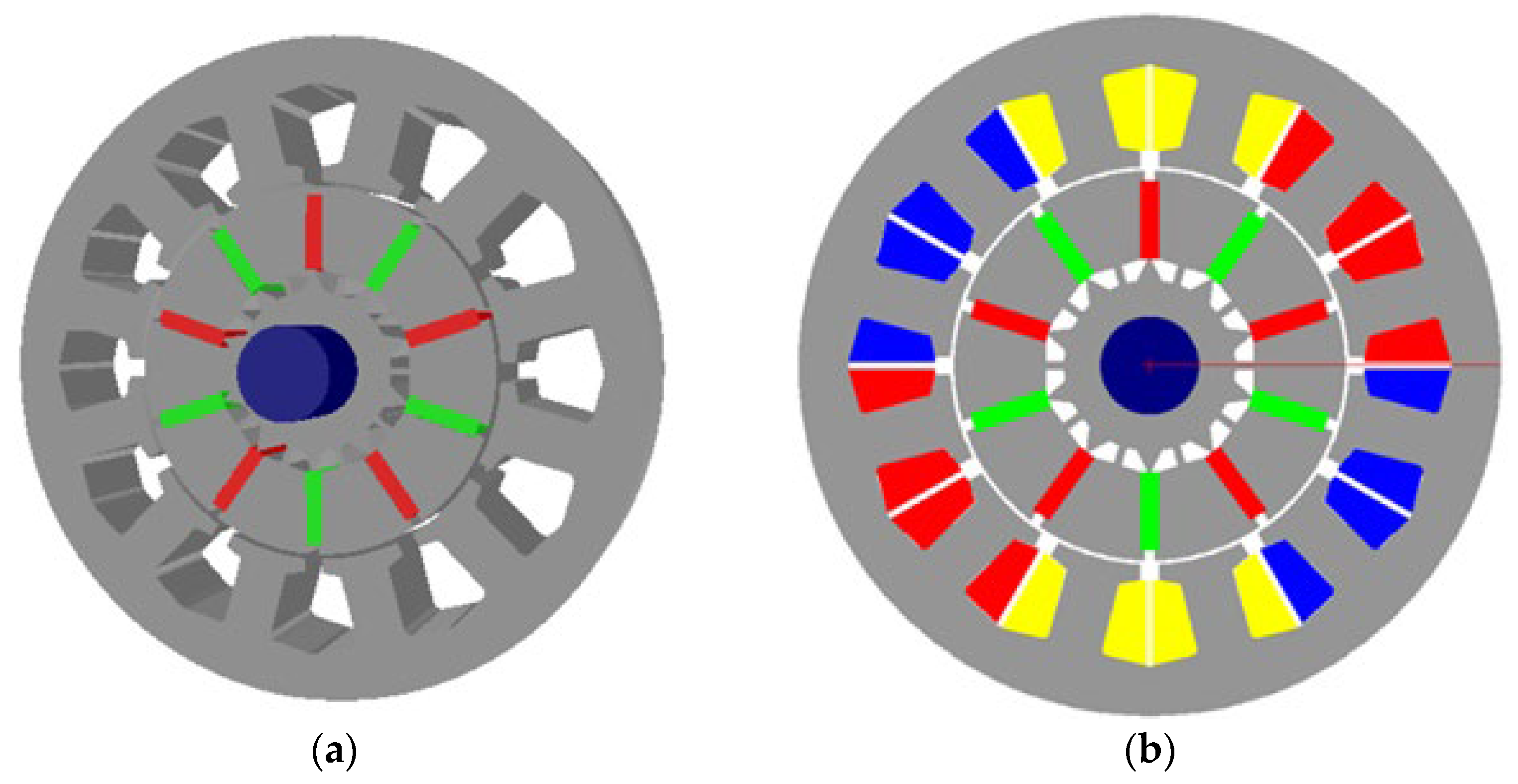
Table 3 presents the results obtained from analytical calculations related to the motor’s geometrical, electrical, and electromagnetic characteristics. These results represent the design outputs based on the input parameters outlined in Table 1 and serve as foundational data for subsequent motor performance analyses. In this context, the PMSM was modeled using the determined design parameters, and motor analyses were conducted using Siemens Simcenter SPEED software (Product Version 2020.3.1). The designed motor model is shown in Figure 1. In this design, a spoke-type rotor structure was preferred. This configuration offers significant advantages in terms of mechanical strength, compact motor construction, and achieving high efficiency. By utilizing the spoke-type rotor structure, leakage fluxes are minimized, enabling magnetic flux interaction between the rotor and stator to occur with minimal leakage. Furthermore, a 12-slot stator and 10-pole rotor combination was selected for the motor topology. This configuration prevents the occurrence of low-order odd harmonic components, such as the 5th, 7th, and 9th, thereby reducing torque ripple and enhancing the overall performance of the motor.
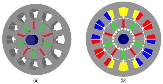
Figure 1.
The designed PMSM: (a) 3D structural view, (b) winding layout.
To further benchmark the electromagnetic performance, the torque per rotor volume (TRV) was evaluated. The designed PMSM achieves a TRV of 25.1 kNm/m3, as reported in Table 3. This metric was adopted instead of envelope-based torque density, since it provides a gearbox-independent and machine-intrinsic normalization of torque capability. Reported TRV values for totally enclosed rare-earth permanent magnet motors generally lie within the range of 14–42 kNm/m3 [26], confirming that the proposed design demonstrates a competitive performance.
Table 3 summarizes the electrical, geometrical, and electromagnetic outputs of the designed PMSM. The selected winding configuration ensures high fundamental component utilization while maintaining compact coil geometry. The relatively high split ratio and aspect ratio were determined based on vehicle constraints, ensuring a balance between torque capability and axial compactness. The average air-gap flux density of 0.62 T and the electrical loading of 22.67 kA/m indicate a moderate magnetic and electric loading, selected to limit saturation and thermal stress under continuous duty. These outputs, together with the geometric parameters such as tooth width and stack length, form the baseline inputs for the FEM-based performance analysis presented in the subsequent section.
3. Results
This section presents the analysis results of the PMSM designed for the electric vehicle. The analyses were carried out using the FEM-based environment of Siemens Simcenter SPEED software. The simulations were performed under the rated operating point in continuous duty, considering a winding temperature of 100 °C. In this process, both the temperature-dependent reduction in the winding resistance and the temperature-dependent decrease in the magnet remanence were taken into account. The copper resistance was calculated by including the end-winding extension height (≈5 mm per side), while the coil configuration of 16 turns per phase with an RMS current density of 5.2 A/mm2 was applied. The efficiency evaluation followed the total losses approach, as defined in IEC 60034-2-1 [28], where core losses were obtained from FEM using the material B–H and loss characteristics and AC copper losses were verified to remain negligible compared to the DC component. The operating point was determined using a maximum torque per ampere (MTPA) current phasing strategy. The current vector angle was determined to be γd = 90.95° with respect to the d-axis, corresponding to a small deviation of 0.95° from the q-axis, indicating that id ≈ 0. The electromagnetic load angle was calculated as δ = 33.88°. These two angles have distinct definitions: γd represents the current vector angle relative to the rotor d-axis, whereas δ denotes the load angle between the rotor flux and the stator flux linkage. At rated operating conditions, such values are typical for spoke-type PMSMs and confirm that the current vector remains predominantly aligned along the q-axis, as expected under MTPA control.
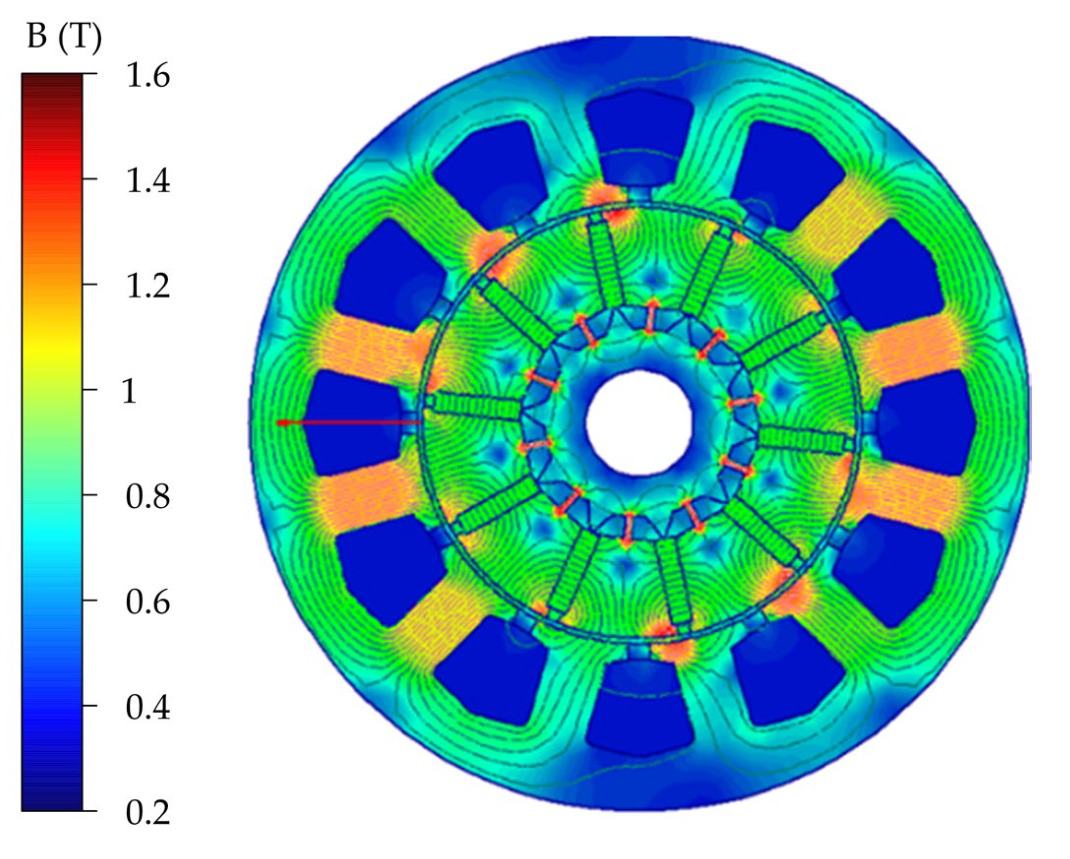
Figure 2 shows the results of the electromagnetic analysis. The primary objective of this analysis is to evaluate whether the core material reaches magnetic saturation. Upon examination of the obtained results, it is observed that magnetic saturation does not occur in the motor core. Remaining below the critical saturation threshold of 1.6 T indicates that the core material has been appropriately selected and that the motor does not pose a risk of saturation under nominal operating conditions. Moreover, the general orientation and symmetry of the flux lines suggest that the motor possesses a magnetically balanced structure.
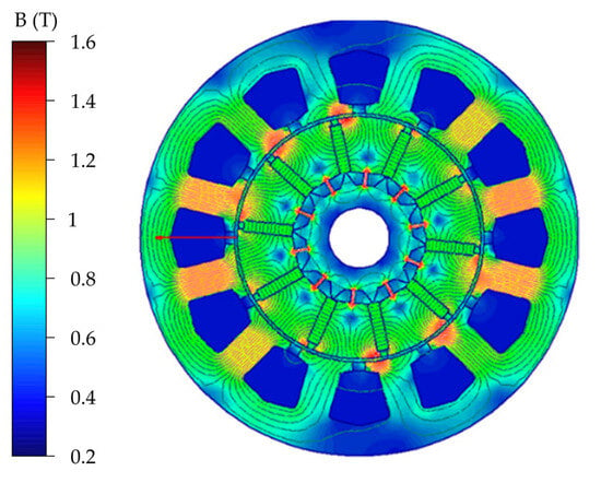
Figure 2.
Magnetic flux density distribution.
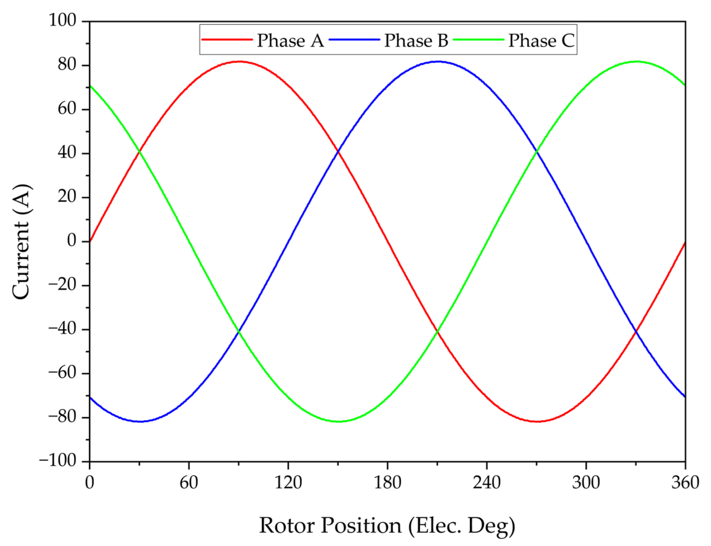
The current waveforms of the three-phase stator windings as a function of the rotor’s electrical position are shown in Figure 3. Each phase of the three-phase system exhibits a sinusoidal waveform with a 120° phase shift between them, indicating that the motor operates under balanced and ideal conditions. The root mean square (RMS) value of the current for each phase is obtained as 59.4 A.
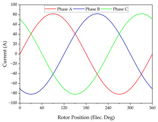
Figure 3.
Three phase stator current waveforms of designed PMSM.
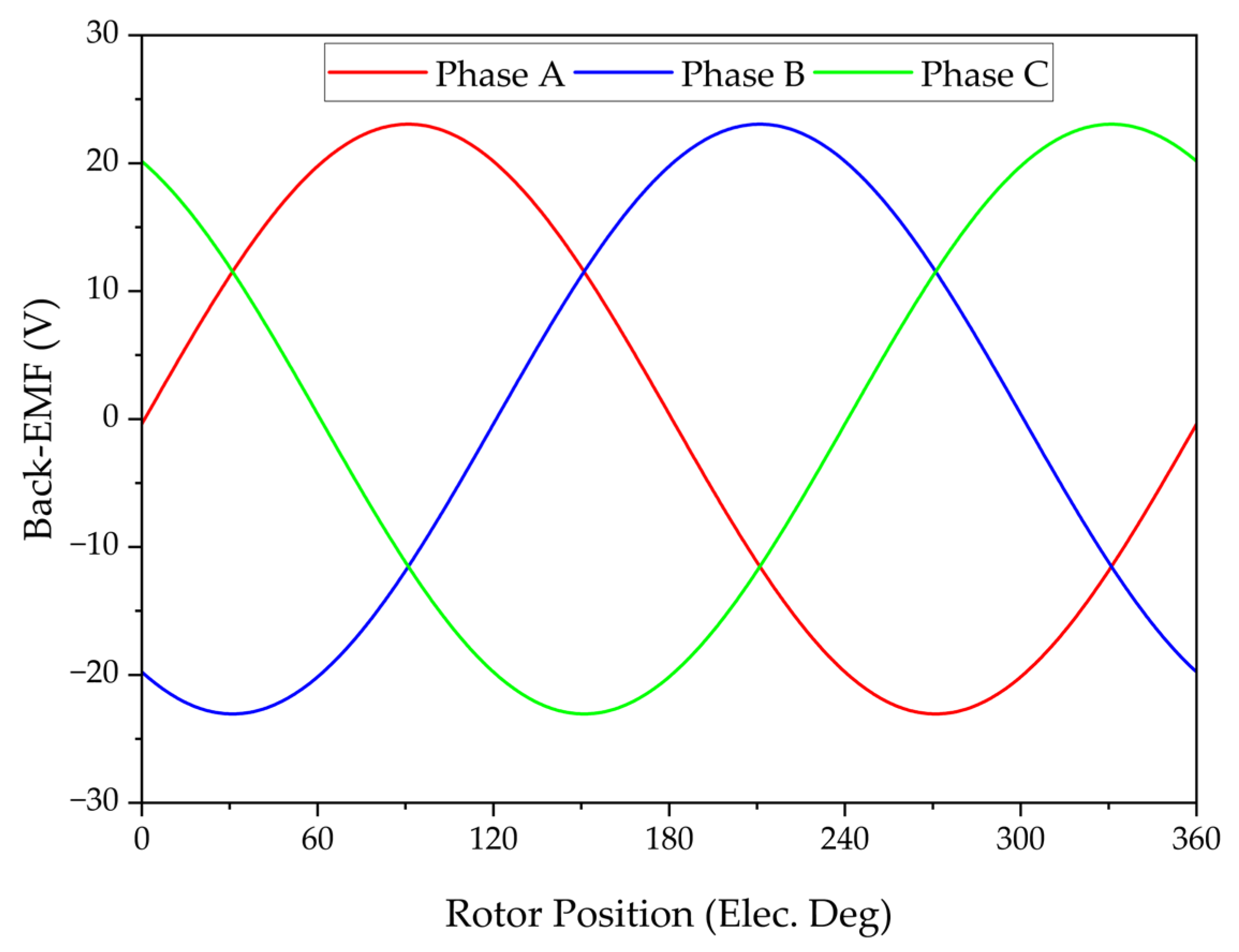
The back-electromotive force (back-EMF) waveforms induced in each phase as a function of the rotor’s electrical position are shown in Figure 4. Each phase exhibits a sinusoidal waveform with a 120° phase shift, indicating a balanced and ideal electromagnetic design. The RMS value of the back-EMF per phase is determined as 16.2 V.
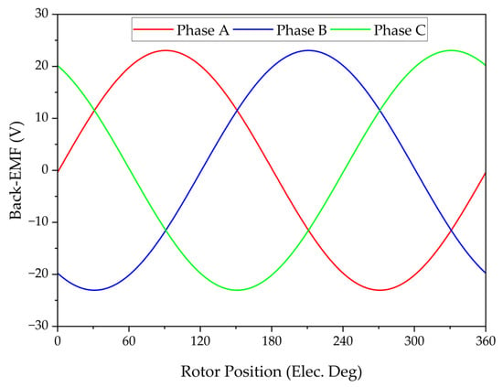
Figure 4.
Three phase back-EMF waveforms of PMSM.
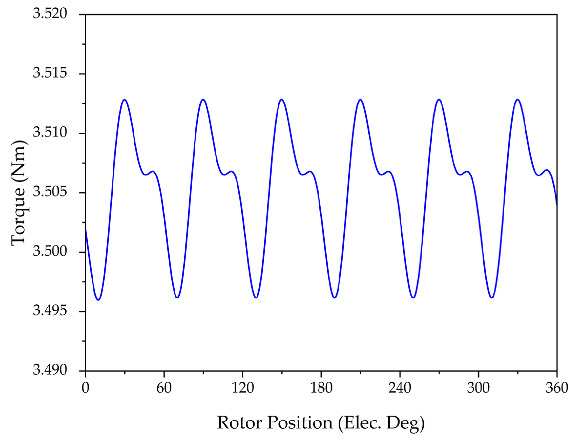
The nominal torque of the motor is approximately 3.504 Nm, as shown in Figure 5. The torque ripple is calculated to be around 0.46% using (1). The low amplitude of torque ripple indicates that the motor has a well-balanced magnetic design and offers high torque stability. From the perspective of electric vehicle applications, this feature provides significant advantages by enhancing driving comfort and the reducing vibrations and noise that may affect mechanical components.
where Tmax, Tmin, and Tavg are maximum torque, minimum torque, and average torque, respectively.
Tr = (Tmax − Tmin)/Tavg
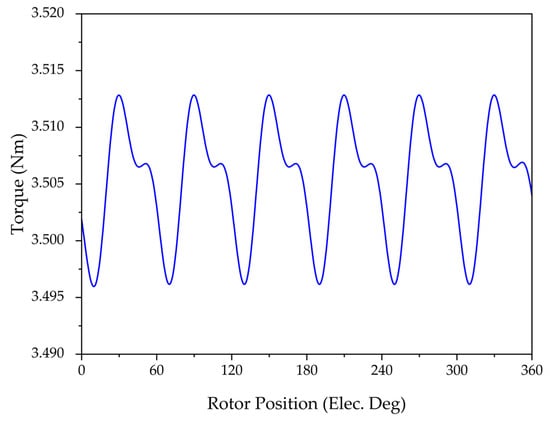
Figure 5.
Electromagnetic torque variation versus rotor electrical position.
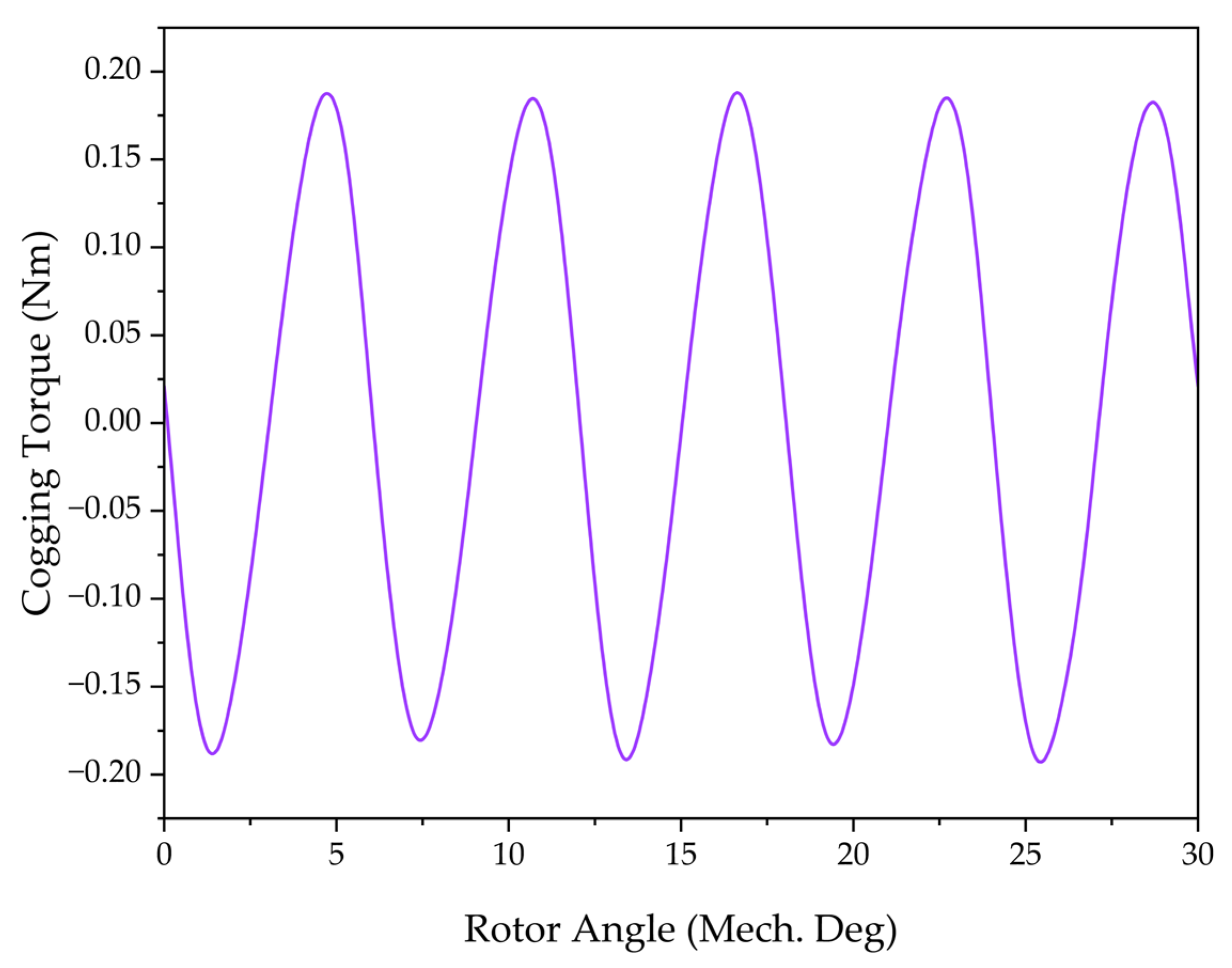
Figure 6 shows the cogging torque waveform obtained over a mechanical rotation of 0–30°. The peak cogging torque is approximately 0.18 Nm. The periodic and symmetrical nature of the waveform indicates a proper alignment between the rotor magnets and stator teeth. In electric vehicle applications, such a low cogging torque level is particularly beneficial at low speeds, where it contributes to smoother and vibration-free operation.
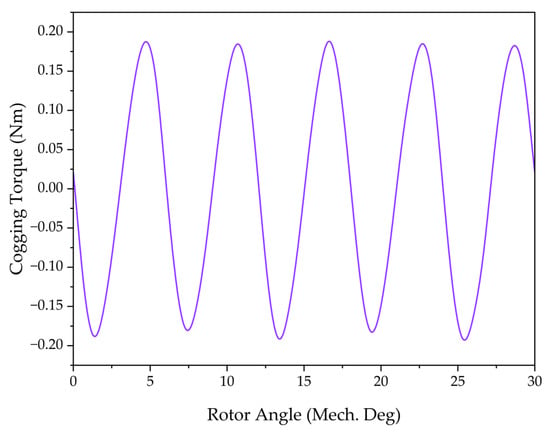
Figure 6.
Cogging torque variation versus rotor electrical position.
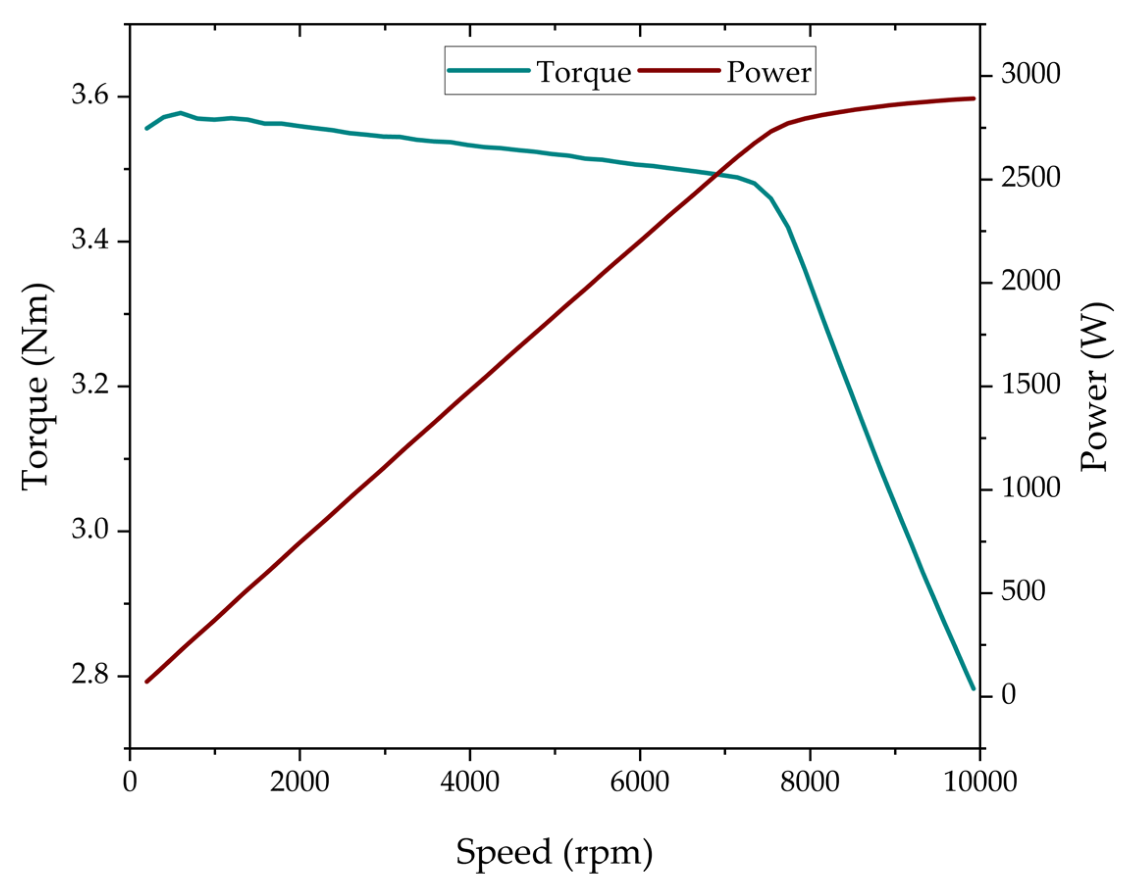
The torque and power characteristics of the designed PMSM are shown in Figure 7 as a function of motor speed. At low speeds, the torque remains nearly constant around 3.5 Nm, but it begins to decrease beyond a certain speed. In contrast, the power increases with speed and reaches approximately 2900 W. At the nominal operating point of 7000 rpm, the torque is 3.5 Nm and the output power is approximately 2.5 kW. This reflects a transition from the constant torque region to the constant power region, which is a desirable performance profile for electric vehicle applications.
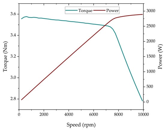
Figure 7.
Operating characteristics of designed PMSM.
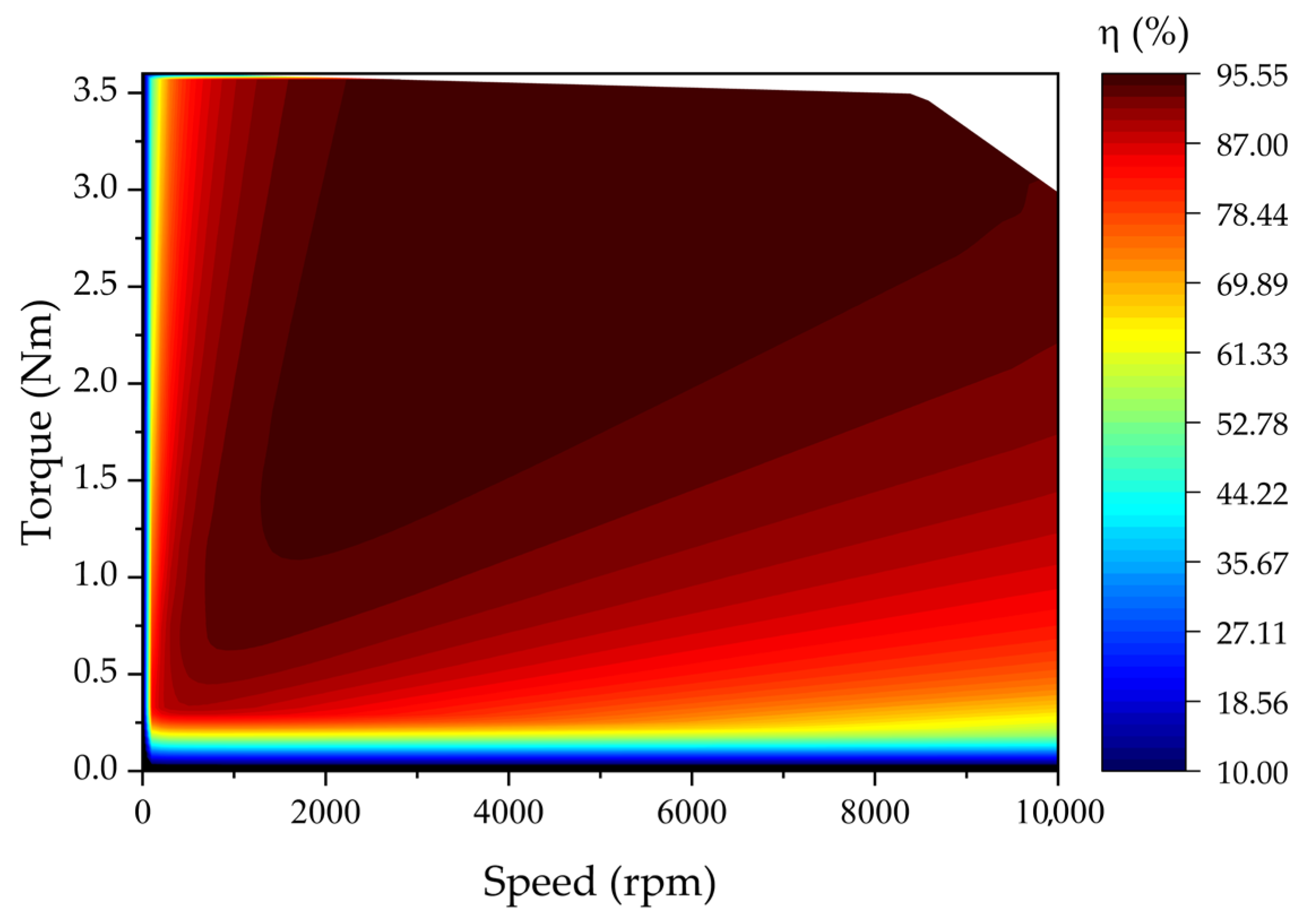
The efficiency map obtained as a function of shaft torque and motor speed is presented in Figure 8. It is observed that the motor operates with an efficiency above 90% over a wide operating range. In particular, high efficiency is achieved within the torque range of 1.5–3.5 Nm and the speed range of 1500–8000 rpm. Under nominal operating conditions, the motor reaches an efficiency of approximately 95.35%, which exceeds the level defined by the highest officially recognized IE5 efficiency class. In the literature, the proposed IE6 classification is associated with approximately 20% lower losses compared to IE5 [24]. Accordingly, the obtained efficiency value meets the expected performance of the IE6 efficiency class, indicating that the motor offers a highly advantageous structure in terms of energy efficiency and overall performance for electric vehicle applications.
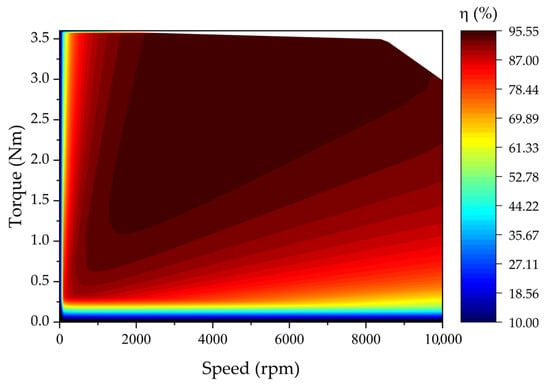
Figure 8.
Efficiency map of the designed PMSM.
The summary of the key electromagnetic and performance parameters of the motor is presented in Table 4. These results highlight that the proposed PMSM achieves a nominal torque of 3.5 Nm and an output power of 2.56 kW at 7000 rpm, with an efficiency of 95.35%. The relatively high power factor confirms the effectiveness of the MTPA-oriented current phasing strategy, while the low winding resistance ensures that copper losses remain small compared to iron losses. The inductance values indicate a saliency ratio close to unity, which is consistent with the spoke-type rotor design and beneficial for stable torque production. Furthermore, the back-EMF constant aligns well with the targeted DC bus voltage, ensuring compatibility with the intended EV drive system. Overall, the parameters confirm that the designed motor offers a balanced combination of high efficiency, compact size, and suitability for geared electric vehicle applications.

Table 4.
Output parameters of the designed PMSM.
4. Conclusions
In this study, a permanent magnet synchronous motor with a spoke-type rotor topology was designed for application in an L-category electric vehicle intended for the urban transportation of two passengers. The motor was tailored to meet the specific torque and speed requirements of the reference vehicle, while also ensuring a compact construction suitable for gearbox integration.
Simulation results showed that the proposed PMSM achieves a peak efficiency of 95.35% under continuous operation, thereby confirming its hyper-efficiency level. The adopted 12-slot/10-pole configuration significantly suppresses low-order harmonics, which reduces torque ripple and contributes to stable drive performance. Magnetic flux analysis further demonstrated that the selected core material remains well below saturation limits, ensuring electromagnetic stability during nominal operation.
In addition, the torque-per-rotor-volume (TRV) of 25.1 kNm/m3 highlights the competitive torque density of the proposed design compared with state-of-the-art permanent magnet machines, while maintaining a lightweight and manufacturable structure.
In conclusion, this study demonstrates the feasibility of achieving both compactness and high efficiency in a PMSM designed for geared electric vehicle applications. In future work, prototype production is planned, and the design will be validated experimentally through efficiency mapping, torque ripple characterization, and thermal performance tests at the electrical laboratory of Volt WEG Group.
Author Contributions
Conceptualization, H.N., S.A., and C.A.; methodology, H.N., S.A., and C.A.; validation, H.N., A.Y., S.A., and C.A.; formal analysis, H.N., S.A., and C.A.; investigation, H.N., A.Y., S.A., and C.A.; writing—original draft preparation, H.N. and A.Y.; writing—review and editing, A.Y.; visualization, A.Y.; supervision, A.Y.; funding acquisition, H.N., S.A. and C.A. All authors have read and agreed to the published version of the manuscript.
Funding
This research was funded by the European Union’s Horizon Europe research and innovation programme under the Grant Agreement 101189783.
Data Availability Statement
The original contributions presented in this study are included in the article. Further inquiries can be directed to the corresponding author.
Acknowledgments
The authors would like to thank Volt WEG Group for their valuable support.
Conflicts of Interest
Authors Hayatullah Nory, Serhat Aksun and Cansu Aksoy were employed by Volt Weg Group. The remaining author declares that the research was conducted in the absence of any commercial or financial relationships that could be construed as a potential conflict of interest.
References
- Fayyazbakhsh, A.; Bell, M.L.; Zhu, X.; Mei, X.; Koutný, M.; Hajinajaf, N.; Zhang, Y. Engine Emissions with Air Pollutants and Greenhouse Gases and Their Control Technologies. J. Clean. Prod. 2022, 376, 134260. [Google Scholar] [CrossRef]
- Rabbi, M.F.; Popp, J.; Máté, D.; Kovács, S. Energy Security and Energy Transition to Achieve Carbon Neutrality. Energies 2022, 15, 8126. [Google Scholar] [CrossRef]
- El, E.; Yildiz, C.; Dandil, B.; Yildiz, A. Effect of Wind Turbine Designed for Electric Vehicles on Aerodynamics and Energy Performance of the Vehicle. Therm. Sci. 2022, 26, 2907–2917. [Google Scholar] [CrossRef]
- Hainsch, K.; Löffler, K.; Burandt, T.; Auer, H.; Crespo del Granado, P.; Pisciella, P.; Zwickl-Bernhard, S. Energy Transition Scenarios: What Policies, Societal Attitudes, and Technology Developments Will Realize the EU Green Deal? Energy 2022, 239, 122067. [Google Scholar] [CrossRef]
- Un-Noor, F.; Padmanaban, S.; Mihet-Popa, L.; Mollah, M.N.; Hossain, E. A Comprehensive Study of Key Electric Vehicle (EV) Components, Technologies, Challenges, Impacts, and Future Direction of Development. Energies 2017, 10, 1217. [Google Scholar] [CrossRef]
- Yang, Y.; He, Q.; Fu, C.; Liao, S.; Tan, P. Efficiency Improvement of Permanent Magnet Synchronous Motor for Electric Vehicles. Energy 2020, 213, 118859. [Google Scholar] [CrossRef]
- Polat, M.; Yildiz, A.; Akinci, R. Performance Analysis and Reduction of Torque Ripple of Axial Flux Permanent Magnet Synchronous Motor Manufactured for Electric Vehicles. IEEE Trans. Magn. 2021, 57, 8106809. [Google Scholar] [CrossRef]
- Agamloh, E.; von Jouanne, A.; Yokochi, A. An Overview of Electric Machine Trends in Modern Electric Vehicles. Machines 2020, 8, 20. [Google Scholar] [CrossRef]
- Monadi, M.; Nabipour, M.; Akbari-Behbahani, F.; Pouresmaeil, E. Speed Control Techniques for Permanent Magnet Synchronous Motors in Electric Vehicle Applications Toward Sustainable Energy Mobility: A Review. IEEE Access 2024, 12, 119615–119632. [Google Scholar] [CrossRef]
- Vlachou, V.I.; Sakkas, G.K.; Xintaropoulos, F.P.; Pechlivanidou, M.S.C.; Kefalas, T.D.; Tsili, M.A.; Kladas, A.G. Overview on Permanent Magnet Motor Trends and Developments. Energies 2024, 17, 538. [Google Scholar] [CrossRef]
- Niu, L.; Zhang, M. Rotor Topology Optimization and Electromagnetic Performance Analysis of Interior Permanent Magnet Synchronous Motors for Electric Vehicle Applications. J. Eng. 2023, 2023, e212240. [Google Scholar] [CrossRef]
- Cheng, Y.; Ding, L.; Zhao, T.; Cui, S. Design and Optimization of Electric Vehicle Traction Motor Considering Rotor Topology and Manufacturing Uncertainty. IEEE Trans. Ind. Electron. 2024, 71, 5034–5044. [Google Scholar] [CrossRef]
- Chu, G.; Dutta, R.; Xiao, D.; Fletcher, J.E.; Rahman, M.F. Development and Optimization of a Mechanically Robust Novel Rotor Topology for Very-High-Speed IPMSMs. IEEE Trans. Energy Convers. 2023, 38, 1781–1792. [Google Scholar] [CrossRef]
- Zhou, C.; Huang, X.; Li, Z.; Cao, W. Design Consideration of Fractional Slot Concentrated Winding Interior Permanent Magnet Synchronous Motor for EV and HEV Applications. IEEE Access 2021, 9, 64116–64126. [Google Scholar] [CrossRef]
- Xi, Z.; Niu, L.; Yan, X.; Xu, L. Research on Performance of Interior Permanent Magnet Synchronous Motor with Fractional Slot Concentrated Winding for Electric Vehicles Applications. World Electr. Veh. J. 2024, 15, 470. [Google Scholar] [CrossRef]
- Fan, X.; Zhang, B.; Qu, R.; Li, D.; Li, J.; Huo, Y. Comparative Thermal Analysis of IPMSMs With Integral-Slot Distributed-Winding (ISDW) and Fractional-Slot Concentrated-Winding (FSCW) for Electric Vehicle Application. IEEE Trans. Ind. Appl. 2019, 55, 3577–3588. [Google Scholar] [CrossRef]
- Tikadar, A.; Johnston, D.; Kumar, N.; Joshi, Y.; Kumar, S. Comparison of Electro-Thermal Performance of Advanced Cooling Techniques for Electric Vehicle Motors. Appl. Therm. Eng. 2021, 183, 116182. [Google Scholar] [CrossRef]
- Shewalkar, A.G.; Dhoble, A.S.; Thawkar, V.P. Review on Cooling Techniques and Analysis Methods of an Electric Vehicle Motor. J. Therm. Anal. Calorim. 2024, 149, 5919–5947. [Google Scholar] [CrossRef]
- Gundabattini, E.; Mystkowski, A.; Idzkowski, A.; Singh, R.R.; Solomon, D.G. Thermal Mapping of a High-Speed Electric Motor Used for Traction Applications and Analysis of Various Cooling Methods—A Review. Energies 2021, 14, 1472. [Google Scholar] [CrossRef]
- Shah, S.H.; Wang, Y.-C.; Shi, D.; Shen, J.-X. Investigation of Torque and Reduction of Torque Ripples through Assisted-Poles in Low-Speed, High-Torque Density Spoke-Type PMSMs. Machines 2024, 12, 327. [Google Scholar] [CrossRef]
- EL-Refaie, A.M.; Shah, M.R.; Alexander, J.P.; Galioto, S.; Huh, K.-K.; Gerstler, W.D. Rotor End Losses in Multiphase Fractional-Slot Concentrated-Winding Permanent Magnet Synchronous Machines. IEEE Trans. Ind. Appl. 2011, 47, 2066–2074. [Google Scholar] [CrossRef]
- Miguel-Espinar, C.; Heredero-Peris, D.; Villafafila-Robles, R.; Montesinos-Miracle, D. Review of Flux-Weakening Algorithms to Extend the Speed Range in Electric Vehicle Applications With Permanent Magnet Synchronous Machines. IEEE Access 2023, 11, 22961–22981. [Google Scholar] [CrossRef]
- IEC 60034-30-3; Rotating Electrical Machines—Part 30-3: Efficiency Classes of High Voltage AC Motors (IE-Code). International Electrotechnical Commission (IEC): Geneva, Switzerland, 2024.
- Wang, J.; Cao, H.; Xie, P. Design of Variable Speed Three-Phase PMSM Series IE6 Efficiency Class. In Proceedings of the 2024 IEEE International Conference on Electrical Energy Conversion Systems and Control (IEECSC), Shanghai, China, 8–10 November 2024; pp. 97–101. [Google Scholar]
- Hendershot, J.R.; Miller, T.J.E. Design Studies in Electric Machines; Motor Design Books LLC: Venice, FL, USA, 2022; ISBN 9780984068746. [Google Scholar]
- Hendershot, J.R.; Miller, T.J.E. Design of Brushless Permanent-Magnet Machines, 2nd ed.; Motor Design Books LLC: Venice, FL, USA, 2010; ISBN 978-0-9840687-0-8. [Google Scholar]
- Miller, T.J.E. SPEED’s Electric Motors: An Outline of Some of the Theory in the Speed Software for Electric Machine Design: With Problems and Solutions; Magna Physics Publishing: Lebanon, OH, USA, 2002; ISBN 978-1-881855-10-1. [Google Scholar]
- IEC 60034-2-1; Rotating Electrical Machines—Part 2-1: Standard Methods for Determining Losses and Efficiency from Tests (Excluding Machines for Traction Vehicles). International Electrotechnical Commission (IEC): Geneva, Switzerland, 2024.
Disclaimer/Publisher’s Note: The statements, opinions and data contained in all publications are solely those of the individual author(s) and contributor(s) and not of MDPI and/or the editor(s). MDPI and/or the editor(s) disclaim responsibility for any injury to people or property resulting from any ideas, methods, instructions or products referred to in the content. |
© 2025 by the authors. Licensee MDPI, Basel, Switzerland. This article is an open access article distributed under the terms and conditions of the Creative Commons Attribution (CC BY) license (https://creativecommons.org/licenses/by/4.0/).

