Article

Novel Adaptive Super-Twisting Sliding Mode Observer for the Control of the PMSM in the Centrifugal Compressors of Hydrogen Fuel Cells

by
Shiqiang Zheng
,
Chong Zhou
* and
Kun Mao
*
School of Instrumentation and Optoelectronic Engineering, Beihang University, Beijing 100191, China
*
Authors to whom correspondence should be addressed.
Energies 2025, 18(17), 4675; https://doi.org/10.3390/en18174675
Submission received: 1 August 2025 / Revised: 21 August 2025 / Accepted: 1 September 2025 / Published: 3 September 2025
(This article belongs to the Special Issue Designs and Control of Electrical Machines and Drives)

Abstract

The permanent magnetic synchronous motor (PMSM) is of significant use for the centrifugal hydrogen compressor (CHC) in the hydrogen fuel cell system. In order to satisfy the demand for improving the CHC’s performance, including higher accuracy, higher response speed, and wider speed range, this paper proposes a novel adaptive super-twisting sliding mode observer (ASTSMO)-based position sensorless control strategy for the highspeed PMSM. Firstly, the super-twisting algorithm (STA) is introduced to the sliding mode observer (SMO) to reduce chattering and improve the accuracy of position estimation. Secondly, to increase the convergence speed, the ASTSMO is extended with a linear correction term, where an extra proportionality coefficient is used to adjust the stator current error under dynamic operation. Finally, a novel adaptive law is designed to solve the PMSM’s problems of wide speed change, wide current variation, and inevitable parameters fluctuation, which are caused by the CHC’s complex working environment like frequent load changes and significant temperature variations. In the experimental verification, the position accuracy and dynamic performance of the PMSM are both improved. It is also proved that the proposed strategy can guarantee the stable operation and fast response of the CHC, so as to maintain the reliability and the hydrogen utilization of the hydrogen fuel cell system.

1. Introduction

With globally increasing energy requirements, there is an emerging trend to replace traditional fossil fuels with clean energy [1]. Hydrogen energy, which is renewable and has high energy density, has been widely studied and utilized in the field of fuel-cell-based electrical vehicles [2]. The hydrogen compressor is a key piece of equipment in hydrogen fuel cell energy systems. The hydrogen compressor driven by a highspeed motor can adjust the flow and pressure of the hydrogen gas to increase the power density and efficiency of the fuel cell system [3]. Compared to the mechanical hydrogen compressors, the centrifugal hydrogen compressor (CHC) has lower cost and higher reliability [4]. The CHC has intricate control demands for high speed and high pressure, a wide adjustable speed range, and high energy utilization efficiency. Permanent Magnet Synchronous Motors (PMSMs) are characterized by superior power density, peak rotational speed, and braking performance, which are consistent with the requirements of the CHC [5]. The CHC of the fuel cell operates under dynamic conditions such as load changes, high power conditions, idling, and startup and shutdown. Insufficient dynamic performance will affect the output voltage and current of the battery pack, causing the failure of the cathode Pt catalyst [6,7,8]. As a result, it is important to improve the dynamic performance of the CHC to achieve a rapid response to the air flow demands under transient working conditions [8,9,10,11]. In addition, the energy efficiency of the CHC needs to be improved to achieve higher efficiency in fuel cell systems.
The PMSM can adjust the gas flow and pressure by controlling the speed of the CHC’s impellor. Field orient control (FOC) is a capable scheme for speed control through coordinate transformation according to the rotor position, so as to control the excitation current and torque current independently [12]. If there exists a position error, the efficiency of the PMSM will decrease. So, it is important to improve the position accuracy of the PMSM [13]. Sensorless control strategies for the PMSM can be generally divided into two categories. The common strategy for motor start or low-speed operation is the high-frequency injection method, which relies on the rotor saliency or magnetic saturation saliency [14]. While in the medium- and high-speed range, the back electromotive force (back EMF) approaches based on the motor model provide better performance. These approaches include the model reference adaptive system [15], the Kalman filter [16], the SMO [17], and so on. Among them, the SMO is widely used in the sensorless control of PMSMs since it has strong robustness to both torque disturbances and parameter variations, and provides good dynamic performance. However, the SMO-based sensorless control method would suffer from two problems: the slow convergence caused by the linear sliding mode surface and the chattering problem caused by the discontinuous control law [18].
Slow convergence speed will degrade the PMSM control performance. Thus, a finite-time extended state observer is designed to provide a faster convergence speed to the sliding mode scheme in [19]. But the electrical and mechanical parameters may be mismatched owing to load torque variations, which will severely deteriorate the dynamic performance of the extended state observer. In [20], an improved adaptive terminal sliding mode reaching law is proposed to ensure the state variables of the control system reach their equilibrium points quickly and suppress the chattering effectively. However, the singularity problem is ignored. The chattering problem will degrade the system stability and estimation accuracy. In [21], a hyperbolic function is selected as the switching function to reduce chattering. But the boundary layer thickness has a tradeoff relationship between the performance of the sliding mode method and the chattering problem. The low-pass filter is usually designed to reduce the chattering and harmonic disturbance. However, the low-pass filter brings a phase delay and position estimation errors for which compensation is needed [22]. In [23], a free-forward phase-lock loop (PLL) is employed to suppress the position error, but it may introduce excessive noise to harm the stability of the observer. In [24], two synchronous frequency-extract filters are proposed to extract the fundamental wave of the rotor position estimation before applying it to the PLL to compensate for the estimation error. But the synchronous frequency-extract filters will increase the calculation time.
The second-order SMO is another effective method which can both increase convergence speed and reduce chattering. In [25], a dual second-order sliding mode disturbance observer structure is proposed to eliminate chattering and provide a high response speed. However, this structure requires the inner and outer disturbances to be estimated separately. The majority of the types of second-order SMO share the difficulty of complex calculation. Therefore, a super-twisting algorithm (STA) is introduced to the second-order SMO in [26]. The super-twisting sliding mode observer (STSMO) converges both the sliding mode variable and its derivative toward zero, without extra high-order calculations. Therefore, the STSMO is widely employed for its simplicity and its ability to inhibit chattering [27]. The performance of the STSMO is sensitive to the selection of switching coefficients. Chattering will be significantly weakened if the appropriate observer coefficients are chosen [28]. The Lyapunov stability principle requires the sliding mode coefficients to be large enough. But the sliding mode coefficients should also be limited in order to reduce disturbance [29]. Obviously, fixed sliding mode coefficients limit the operation range, and inappropriate coefficients may bring large estimation errors.
Therefore, it is effective to develop coefficient adaptive algorithms against flexible operating conditions. Several coefficient adaptive algorithms have been proposed in recent years. The STA in [30] is based on a single-designed coefficient instead of the two coefficients required in the classic STA. Then, the single-designed coefficient can be tuned according to the sufficient conditions to ensure the finite-time convergence toward zero. A modified speed adaptive STSMO with a moving average filter PLL is deployed in [31] to accurately estimate the position and speed of the PMSM. A modified STSMO adjusts the sliding mode coefficients by online identification of the stator resistance and of the initial angular position. It shows good performance for the start and low-speed operation of the test PMSM [32]. In [33], an adaptive law is designed to adjust the sliding mode coefficients with the rotational speed variation. Meanwhile, the performance of the SMO for PMSM at high speed is related to not only the stator resistance and rotational speed, but also to the flux and current. And ignorance of these variables will influence the SMO performance in a wide speed and current range.
In order to achieve the demand of high flow rate and high pressure from the CHC, the sampling frequency of the highspeed PMSM should be high enough compared with the operation frequency to reach a higher peak rotational speed. In this case, the short control period will limit the system stability, dynamic performance, and position estimation accuracy [34]. Also, the increased switching frequency will enlarge the effect of control delay, which will lead to a worse chattering phenomenon [35]. In addition, the complex operating conditions of the CHC will lead to parameters fluctuation for the PMSM, which in turn affects the accuracy of the sensorless position estimation. For example, the stator resistance’s value varies linearly with temperature, and the winding inductance as well as the flux linkage are influenced by the magnetic saturation. Therefore, this paper proposes a novel ASTSMO for the operation of a highspeed PMSM with a wide current range. The proposed method has the following advantages over the conventional ASTSMO:
  • This paper proposes an improved STSMO model, which can increase the convergence speed of the SMO against sudden current change.
  • This paper prosses a novel adaptive law of the STSMO. This adaptive law considers the influences of motor parameters, speed, and current change. Therefore, the STSMO using this adaptive law can suppress chattering and maintain high accuracy on complex operating conditions over a wide range of speed variations or current fluctuations.
The rest of this paper is organized as follows. Section 2 analyzes the model of the SPMSM and conventional ASTSMO. Section 3 proposes the modified STSMO model and its stability proof. The novel adaptive law is also introduced. Section 4 gives the experimental verification. Section 5 is the final conclusion.

2. Conventional ASTSMO for PMSM Control

2.1. Basic Theory of FOC Strategy

The hydrogen fuel cell power system is comprised of four subsystems: the fuel cell stack, the hydrogen circulation system, the oxygen circulation system, and the water–heat management system, as shown in Figure 1. The CHC is the core equipment in the hydrogen circulation system. It is used to recycle the unreacted hydrogen gas from the fuel cell stack exports, and push it back to the entrance, which can help improve the hydrogen utilization and reliability. Additionally, the CHC can transfer the reaction-produced water to the import channel, and humidify the inlet gases as a result. There are several critical requirements for the CHC. The CHC must provide high speed and high pressure to satisfy the gas supply and system power demands. The CHC must have a broad speed range and swift adaptability against load changes to address varying operational demands. Furthermore, the CHC must have high efficiency to reduce the energy cost in the fuel cell system. The PMSM can fulfill the demands above with its advantages of high power density, high peak speed, rapid braking, high efficiency, and reduced torque ripple.
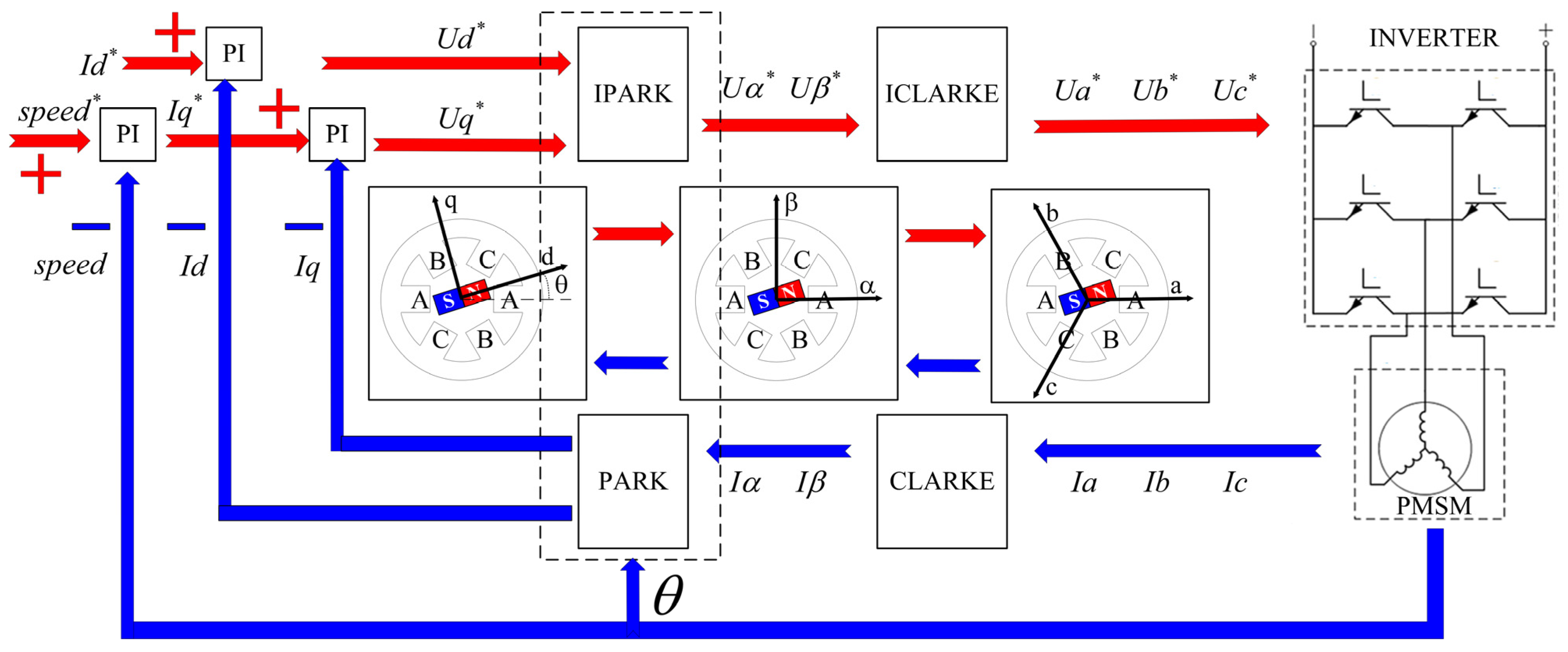
Generally, the highspeed PMSM is controlled by the FOC strategy, as shown in Figure 2. The PI controller will translate the error between the target speed* and feedback speed into a precise current control signal Iq*. The voltage control signals Uq* and Ud* will be translated to the three-phase voltage Ua*, Ub*, and Uc*, according to the coordinate transformation process IPARK and CLARKE. As a consequence, the three-phase current generated in the motor coils will create a rotating magnetic field, which can drive the pressurized impeller to compress the hydrogen gas. The rotor position is significant in the coordinate transformation process, since the position error will lead to excessive current cost and reduce the CHC’s efficiency. In addition, the delay of the feedback speed will reduce the response speed. Therefore, this paper aims to modify the conventional SMO to optimize the estimation of the position and speed of the PMSM.

2.2. Model of SMO in PMSM Control Systems

In order to facilitate the application of the CHC, the PMSM studied in this paper has the following characteristics.
  • The inductance of the d-axis is approximately equivalent to that of the q-axis.
  • The magnetic field is sinusoidally distributed in space.
  • The effect of magnetic cross-saturation is neglected.
The current equation of the employed PMSM in the α-β frame can be described as follows:
d d t i α i β = R L i α i β + 1 L u α e α u β e β
where uα, uβ, iα, iβ, eα, and eβ represent the voltages, the currents, and the back electromotive forces (back EMFs) in the α-β frame, respectively. R and L are, respectively, the stator resistance and inductance. The back EMFs can be translated to e α e β T = - ω e ψ f sin θ ω e ψ f cos θ T , where ωe is the rotor speed, ψf is the flux linkage, and θ is the rotor position.
According to (1), the SMO can be designed as follows:
d d t i ^ α i ^ β = R L i ^ α i ^ β + 1 L u α v α u β v β ,
where v α v β T represents the sliding mode control law. Then, an equation of current error can be obtained by subtracting (2) from (1).
d d t i ˜ α i ˜ β = R L i ˜ α + 1 L e α 1 L v α R L i ˜ β + 1 L e β 1 L v β ,
where i ˜ = i ˜ α i ˜ β T represents the current error. When the current error approaches 0, v α v β T can be regarded as the estimation of e α e β T . Furthermore, the rotor position and speed information can be obtained by an arctangent function or a phase-locked loop (PLL) [14,15].

2.3. Super-Twisting Algorithm

The high-order SMOs can both reduce chattering and improve control accuracy and dynamic response speed. However, the complexity of the major high-order SMOs limits their operation. One of the most popular employed high-order sliding mode laws is the super-twisting algorithm (STA) in which extra high-order calculations are not required. The formula of the STA is given in (4):
x ˙ 1 = k 1 x 1 sign x 1 + x 2 + ρ 1 x , t x ˙ 2 = k 2 sign x 1 + ρ 2 x , t ,
The robustness of the globally asymptotic stability of the equilibrium of (4) in finite time is proved to be guaranteed by the following conditions [36]:
ρ 1 δ 1 x 1 ρ 2 δ 2 ,
If there exists a positive constant δ1 that satisfies the inequalities in (5), the conditions of the two coefficients, k1 and k2, given in (6) can guarantee the stability of (4).
k 1 > 2 δ 1 k 2 > k 1 5 δ 1 k 1 + 6 δ 2 + 4 δ 1 + δ 2 / k 1 2 2 k 1 2 δ 1 ,
With the super-twisting algorithm in (4), the current error equation of the SMO in (3) can be translated to (7), which is the STSMO.
d d t i ˜ α i ˜ β = R L i ˜ α + 1 L e α 1 L K 1 i ˜ α sign i ˜ α + t 0 t 1 K 2 sign i ˜ α d t R L i ˜ β + 1 L e β 1 L K 1 i ˜ β sign i ˜ β + t 0 t 1 K 2 sign i ˜ β d t ,
Equation (8) shows the corresponding relationships between the variables in (7) and (4).
k 1 = K 1 L , k 2 = K 2 L x 1 = i ˜ α i ˜ β , x 2 = t 0 t 1 K 2 L sign i ˜ α i ˜ β d t ρ 1 = R L i ˜ α i ˜ β + 1 L e α e β , ρ 2 = 0 ,
This algorithm makes the sliding mode variable i ˜ = i ˜ α i ˜ β T and its first derivative converge near the sliding mode surface. As a result, the change rate of the sliding mode variable near the sliding mode surface is lower, the chattering is smoother, the number of oscillations is fewer, the convergence is faster, and complex calculation is no longer needed.

2.4. Conventional Adaptive STSMO

Although the coefficients can be designed according to the stable condition of the STSMO given in (5) and (6), fixed coefficients cannot maintain good performance in all operating conditions. Large sliding mode coefficients may lead to severe chattering and even instability in the low-speed range, while small sliding mode coefficients may cause instability at high speeds [25]. Therefore, an adaptive law of sliding mode coefficients can greatly improve the performance of the STSMO.
Assuming that the voltage drop across the stator resistance in the perturbation can be neglected, the global boundary in (7) can be rewritten as follows:
ρ 1 1 L ω e ψ f sin θ ω e ψ f cos θ δ 1 i ˜ α i ˜ β ,
There must be a large enough constant η1 that satisfies the following inequality:
ρ 1 η 1 ω e x 1 ,
Then, the conventional adaptive law can be designed as follows:
K 1 = σ 1 ω e K 2 = σ 2 ω e 2 ,
The STSMO will be stable if the constants σ1 and σ2 are large enough. In the conventional adaptive ASTSMO, the coefficients are commonly adjusted with the variation in rotor speed. However, when translating Equation (8) into (9), the voltage drop across the stator resistance is neglected in the conventional ASTSMO, which shall affect the accuracy of the position estimation.

3. The Proposed Method of Novel ASTSMO

3.1. STSMO with Linear Term

The conventional STSMO has a strong convergence ability near the sliding mode surface and can handle the strong perturbations near the origin. But it has difficulty enduring a linearly growing perturbation and may have a problem dealing with perturbations far away from the origin.
It is important to consider that the current disturbance may strongly affect the performance of the PMSM with a wide current range. When the current changes suddenly, the instantaneous current error is far from the sliding mode surface, and the convergence time of the conventional STSMO may limit the current tracking speed. Therefore, in this paper, an advanced STSMO with a linear correction term is used to improve the dynamic performance of the STSMO. The modified STSMO that combines the linear and nonlinear terms can maintain the strong convergence ability near the sliding mode surface while improving the convergence ability far away from the sliding mode surface with the effect of linear correction. Equation (12) gives the redesigned model of the current error:
d d t i ˜ α i ˜ β = R L i ˜ α + 1 L e α 1 L K 1 i ˜ α sign i ˜ α + t 0 t 1 K 2 sign i ˜ α d t + K 3 i ˜ α R L i ˜ β + 1 L e β 1 L K 1 i ˜ β sign i ˜ β + t 0 t 1 K 2 sign i ˜ β d t + K 3 i ˜ β ,
where K3 is the coefficient of the linear correction term. The proposed STSMO in (12) can guarantee the fast convergence of the sliding mode variable both near or far from the sliding mode surface, on the condition that the system is stable.

3.2. Stability Analysis

In order to meet the stability requirements, the values of the sliding mode coefficients are analyzed as follows. Take the α phase as an example. Firstly, a Lyapunov function is designed as W = M TPM. The definition of the matrices is as follows:
M = i ˜ α sign i ˜ α i ˜ α t 0 t 1 K 2 L sign i ˜ α d t ,
P = 2 K 2 L + K 1 2 2 L 2 K 1 K 3 2 L 2 K 1 2 L K 1 K 3 2 L 2 K 3 2 2 L 2 K 3 2 L K 1 2 L K 3 2 L 1 ,
W = M T P M = 2 K 2 L i ˜ α + 1 2 t 0 t 1 K 2 L sign i ˜ α d t 2 + 1 2 K 1 L i ˜ α sign i ˜ α + K 3 L i ˜ α t 0 t 1 K 2 L sign i ˜ α d t 2 > 0 ,
It is clear that Function W is positively defined. Then, the proposed STSMO should be stable as long as the derivative of W is negatively defined. The description of is shown in (16):
W ˙ = 1 i ˜ α M T Q 1 M M T Q 2 M + 1 i ˜ α q 1 T M + q 2 T M ,
where the coefficient matrices are described as follows:
Q 1 = K 1 K 2 L 2 + K 1 3 2 L 3 0 K 1 2 2 L 2 0 5 K 1 K 3 2 2 L 3 3 K 1 K 3 2 L 2 K 1 2 2 L 2 3 K 1 K 3 2 L 2 K 1 2 L ,
Q 2 = K 2 K 3 L 2 + 2 K 1 2 K 3 L 3 0 0 0 K 3 3 L 3 K 3 2 L 2 0 K 3 2 L 2 K 3 L ,
q 1 T = ρ 1 K 1 2 2 L 2 + 2 K 2 L 0 K 1 2 L ,
q 2 T = ρ 1 3 K 1 K 3 2 L 2 K 3 2 L 2 K 3 L ,
In order to give a sufficient condition to satisfy that is negative, it is assumed that there exist two positive constants δ1 and δ2 satisfying the following inequality in (21):
ρ 1 = 1 L R i ^ α + e α δ 1 i α 1 2 + δ 2 i α ,
The following inequations can be obtained on the condition that ρ 1 δ 1 i α 1 2 + δ 2 i α .
1 i ˜ α 1 2 q 1 T M δ 1 i ˜ α 1 2 M T Δ 1 M + δ 2 M T Δ 1 M q 2 T M 1 i ˜ α M T Δ 2 M + M T Δ 3 M ,
where the coefficient matrices are described as follows:
Δ 1 = 2 K 2 L + K 1 2 2 L 2 0 K 1 4 L 0 0 0 K 1 4 L 0 0 ,
Δ 2 = 0 0 0 0 3 K 1 K 3 δ 2 2 L 2 + K 3 2 δ 1 L 2 0 0 0 0 ,
Δ 3 = 3 K 1 K 3 δ 1 2 L 2 0 K 3 δ 1 2 L 0 K 3 2 δ 2 L 2 K 3 δ 2 2 L K 3 δ 1 2 L K 3 δ 2 2 L 0 ,
Therefore, if the condition in (21) is satisfied, the following inequation can be obtained according to (16) and (22):
W ˙ < 1 i ˜ α M T Q 1 Δ 2 δ 1 Δ 1 M M T Q 2 Δ 3 δ 2 Δ 1 M
If the following inequality in (27) is satisfied, Function is negatively defined:
Q 1 Δ 2 δ 1 Δ 1 > 0 Q 2 Δ 3 δ 2 Δ 1 > 0
On the condition that (27) is satisfied, the proposed STSMO with linear terms is stable. By substituting (17), (18), (23), (24), (25) into (27), the stable condition is equal to (28):
K 1 > 2 δ 1 L K 3 > 2 δ 2 L K 2 > K 1 δ 1 K 1 + 1 8 δ 1 2 L K 1 2 δ 1 L   if   ρ 1 δ 1 i ˜ α + δ 2 i ˜ α

3.3. Design of Adaptive Law

In order to guarantee the stability of the proposed ASTSMO, the constants δ1 and δ2 are designed as follows:
δ 1 = ω e ψ f ω 0 ψ f 0 δ 10 δ 2 = δ 20 + R L , δ 20 > 0
where ω0 is the rated rotor speed and ψf0 is the designed flux linkage. Since the rotor speed and flux linkage are bounded, there is little doubt about finding a large enough initial value δ10 that satisfies the inequation in (30):
δ 10 i ˜ α 1 2 > 1 L ω e 0 ψ f 0
δ20 is decided by a proportional component in (31):
δ 20 = k p i ˜ α
Kp is the proportionality coefficient. The larger Kp is, the faster the response is, but the less the stability is. The smaller Kp is, the more stable it is, but the slower the convergence is. Generally speaking, the value of the proportionality coefficient ranges from 0.1 to 50, and Kp = 2 is selected particularly in this paper.
On the condition that (30) and (31) are satisfied, the designed values δ1 and δ2 in (29) can satisfy the inequality in (21), as shown below.
δ 1 i ˜ α 1 2 + δ 2 i ˜ α = ω e ψ f ω 0 ψ f 0 δ 10 i ˜ α 1 2 + δ 20 i ˜ α + R L i ˜ α > 1 L ω e ψ f + R L i ˜ α 1 L R i ^ α + e α = ρ 1
In this case, the sliding mode coefficients can be designed as (33):
K 1 = 2 + ε δ 1 L K 3 = 2 + ε δ 2 L K 2 > K 1 δ 1 K 1 + 1 8 δ 1 2 L K 1 2 δ 1 L = 2 + ε 17 8 + ε δ 1 2 L ε
Then, the stability condition in (28) can be satisfied as long as ε > 0.
An excessive coefficient of the ASTSMO will enhance the chattering phenomenon and decrease the control performance of the system. Therefore, the value of ε should be properly adjusted. In order to minimize the chattering and harmonic disturbance of the observer, the coefficients should be set up to be as small as possible on the premise of stability.
The following function can be constructed:
F ε = 2 + ε 17 8 + ε ε ,
The differentiation of Equation (34) is as follows:
d d t F ε = 33 8 + 2 ε ε 17 4 + 33 8 ε + ε 2 ε 2 ,
It can be deduced that, when ε = 17 2 , the F ε function takes the minimum value of F ε = F ε min = 33 8 + 17 .
A novel adaptive law of sliding mode coefficients can be deduced according to (29), (30), (31), and (33):
K 1 = 2 + 17 2 ω e ψ f δ 10 L ω 0 ψ f 0 K 3 = 2 + 17 2 δ 20 + R L K 2 = 33 8 + 17 ω e 2 ψ f 2 δ 10 2 L ω 0 2 ψ f 0 2
The same adaptive law can be employed in the β phase as well. On the premise of the stability condition mentioned above, the adaptive law in (36) can adjust the sliding mode coefficients according to the real-time changes in rotor speed, stator resistance, inductance, flux linkage, and current.
At low speed, the values of K1 and K2 are small. And the resistance variation can have a great effect on the system. On the other hand, at high speed, the influence of resistance can be ignored. At the same time, the value of K3 is small when the current is stable. In this case, the adaptive law is similar to the conventional one in (11). Therefore, the proposed novel ASTSMO can cover the working field of the classic STSMO on a static operation. Additionally, it can improve the dynamic performance by accelerating the convergence speed.
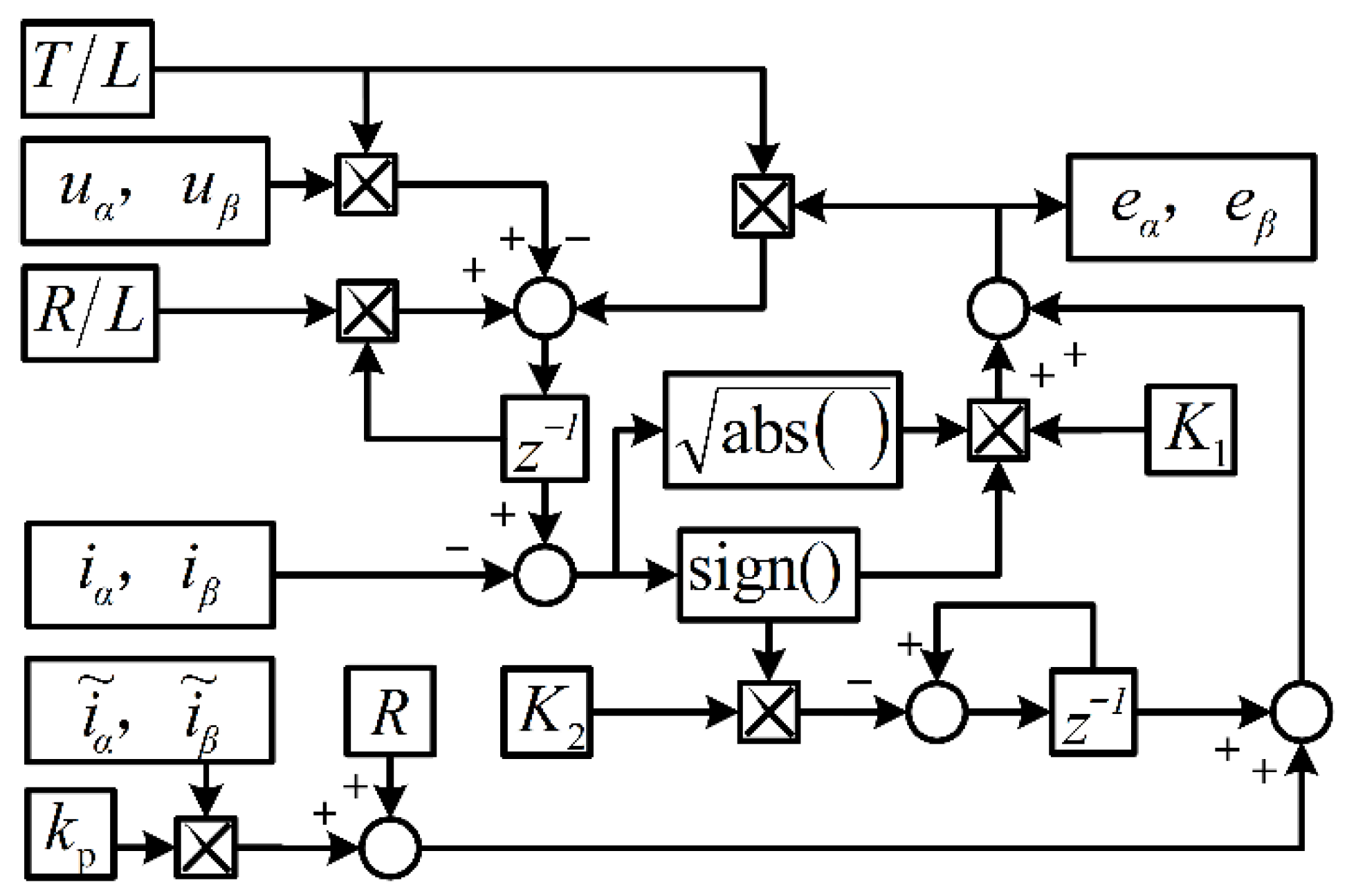
To sum up, the coefficients of sliding mode are adaptively related to the rotor speed ωe, the stator resistance R, the stator inductance L, the flux linkage ψf, and the current error i ˜ . The adaptive law is adopted in the ASTSMO model in (12), in order to realize an implement adaptive observation towards the back EMFs of the PMSM. The structural model of the discrete ASTSMO is as shown in Figure 3.
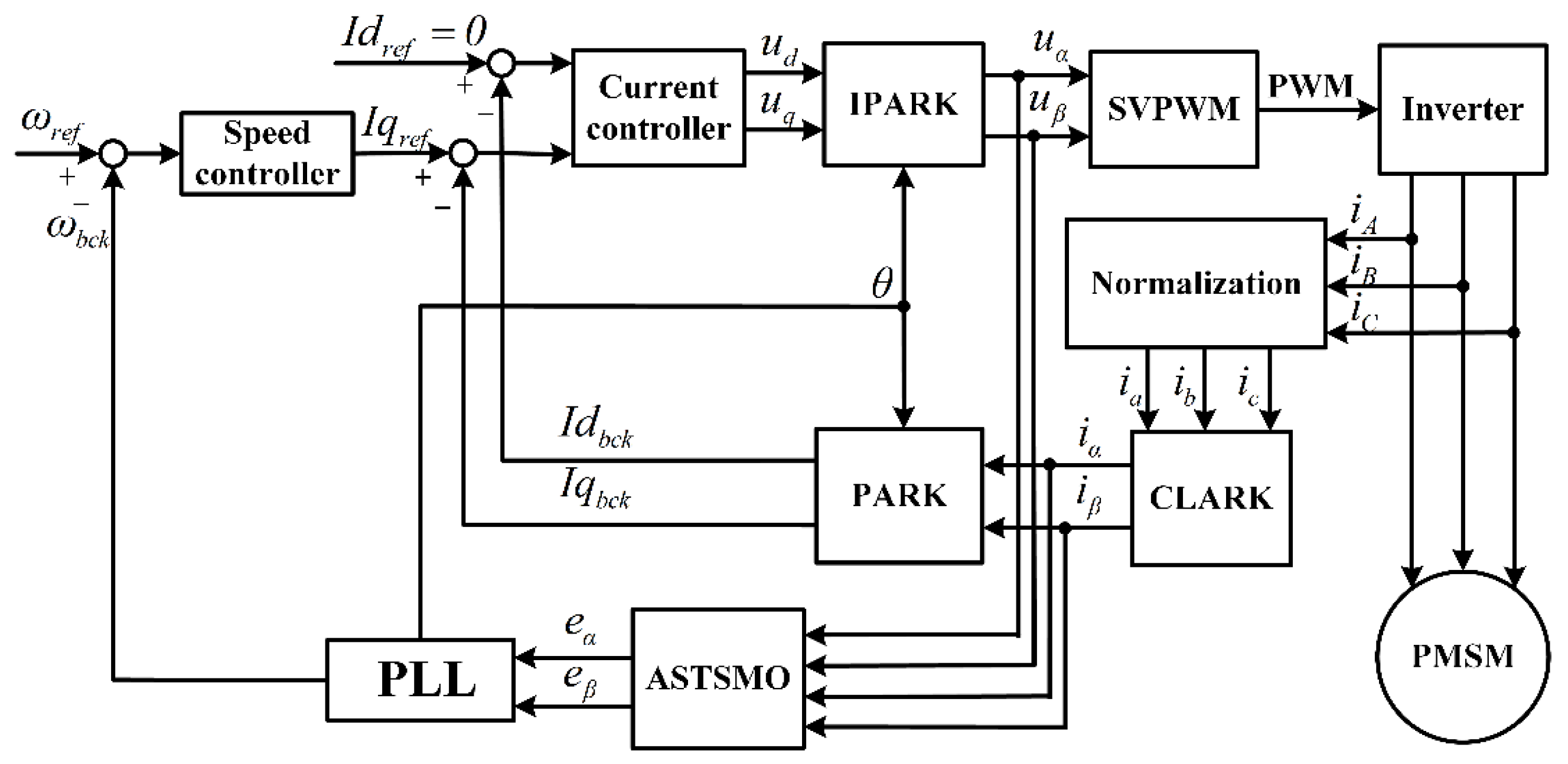
The overall driving scheme of magnetic field-oriented control for the PMSM based on the proposed ASTSMO is shown in Figure 4. The magnetic field-oriented control method is used for the double closed-loop control of speed and current. ωe is estimated through the PLL function. The coefficients of the ASTSMO change with the variation in speed and the current. Through this strategy, the chattering will be reduced, and the stability and dynamic performance will be improved.

4. Experiments and Discussions

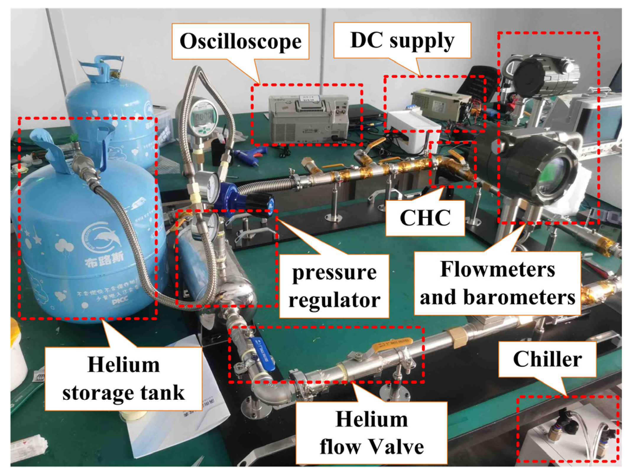
In order to verify the effectiveness of the proposed scheme, a gas circulation platform is built as shown in Figure 5. Helium gas is used instead of hydrogen gas for the consideration of safety. The gas flow and pressure can be measured by the flowmeters and barometers separately. And the pressure ratio can be obtained through the inlet and outlet gas pressure. Table 1 gives the parameters of the PMSM consisting of the test CHC. The nominal value of the stator resistance and inductance are measured offline using the E4980A LCR (manufacturer: Keysight Technologies, Santa Rosa, CA, USA) digital bridge from Agilent. The nominal value of flux linkage is obtained by measuring the back electromotive force while dragging the motor at a low speed. The phase current is measured by a CP1000A current probe of CYBERTEK, and is stored by an Agilent DOSX2024A oscilloscope (manufacture: Keysight Technologies). The real position and speed of the rotor are measured by the iC-TW39 (manufacture: iC-Haus, Bodenheim, Germany) series magnetic angle sensor, and converted into digital signals by a quadrature encoder. The above sampled signals are only used for experimental comparison and are not involved in the operation of the proposed control strategy. The proposed sensorless control strategy is realized via the circuit board in Figure 6. The integrated driver chip DRV8323 (manufacture: Texas Instruments, Dallas, TX, USA) is used for the generation of the driver signal and current sampling. The DSP chip TMS320f28377 (manufacture: Texas Instruments) is used for the calculation of the FOC and the ASTSMO scheme. The inverter switching frequency is set to 20 kHz, and the dead time is set to 2 μs. The sampling time of the SMO algorithm is 50 μs.

4.1. Simulation Results

A simulation study (with sampling time T = 50 μs) of the proposed methods is carried out using a PMSM with specifications as in Table 1.
There are three observers employed in the simulation model separately: the STSMO with fixed coefficients, the conventional adaptive STSMO, and the proposed novel ASTSMO.
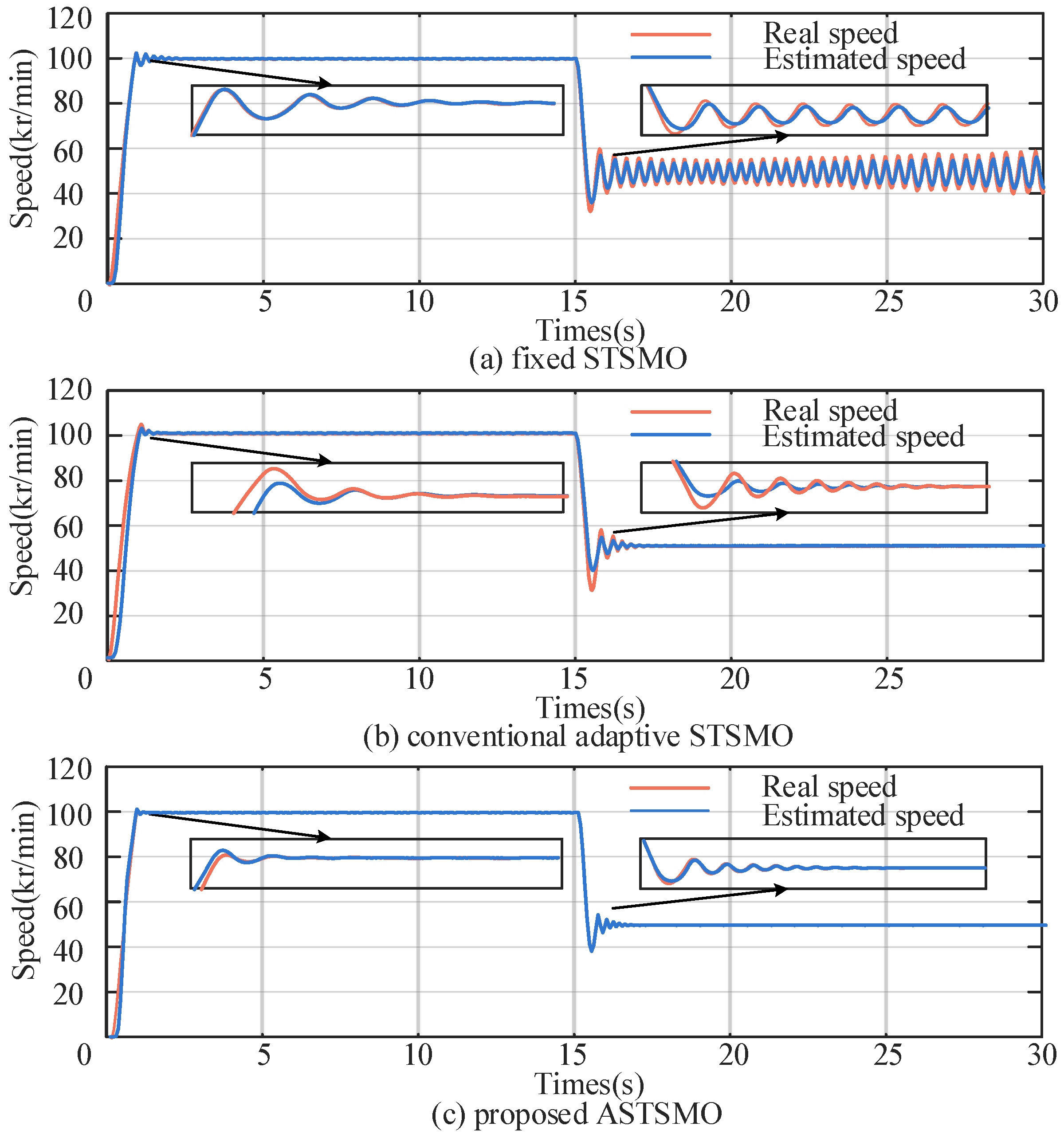
Figure 7a–c demonstrate the performance of the PMSM with the following conditions. The PMSM is accelerated to a reference speed of 100 kr/min, and decelerated to 50 kr/min at 15 s. The real speed and estimated speed are extracted for comparison. It can be seen that the fixed STSMO performs well at the rated speed, but the speed tends to divergence at 50 kr/min. The conventional adaptive STSMO performs well at both high and low speeds. But the estimated speed of the conventional adaptive STSMO has a poor tracking ability and has significant overshoot. On the contrary, the proposed ASTSMO not only reduces chattering at steady state, but also provides lower overshoot under dynamic operations.

4.2. Steady State Performance Experiment

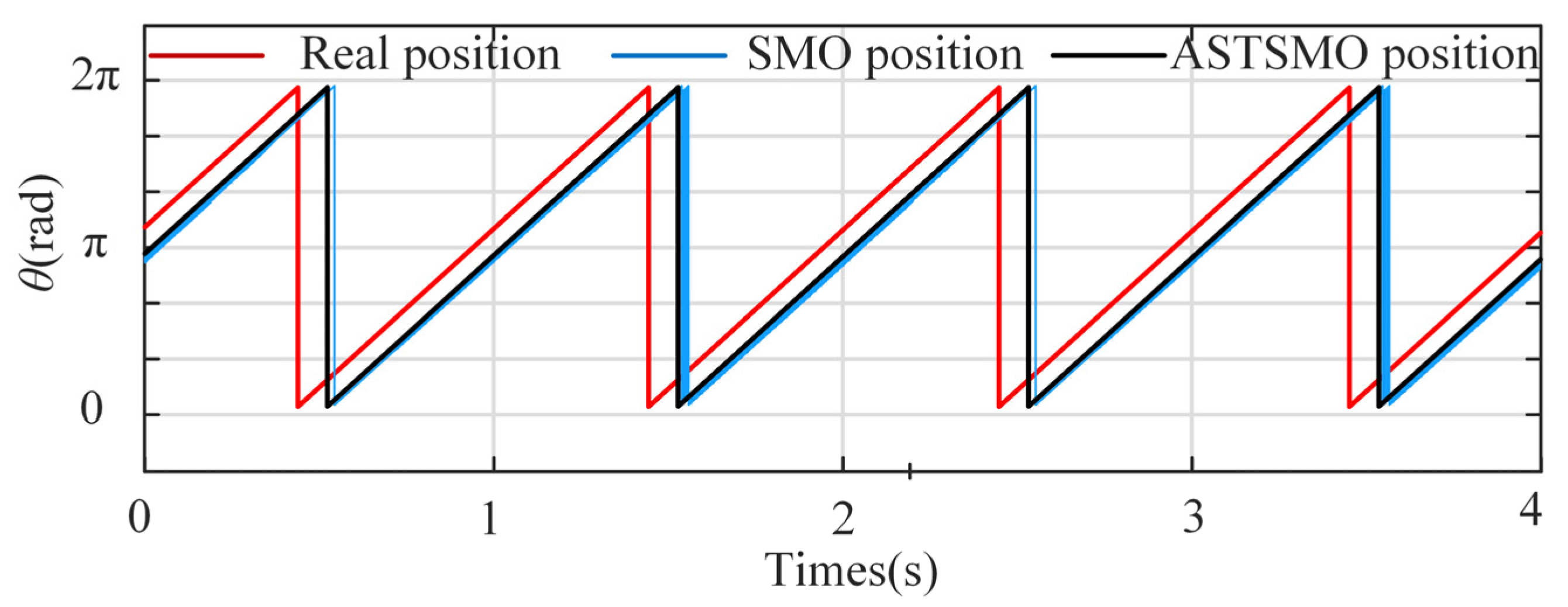
Since the back EMF is zero when the rotor is stationary, the speed cannot be detected by the back EMF-based method. Therefore, the motor is started by V/F control and switched to FOC control with the SMO algorithm after the speed reaches 60 r/min. The position estimation results at 60 r/min are shown in Figure 8. The position errors of both the conventional STSMO and the proposed scheme are more than 0.3 rad.
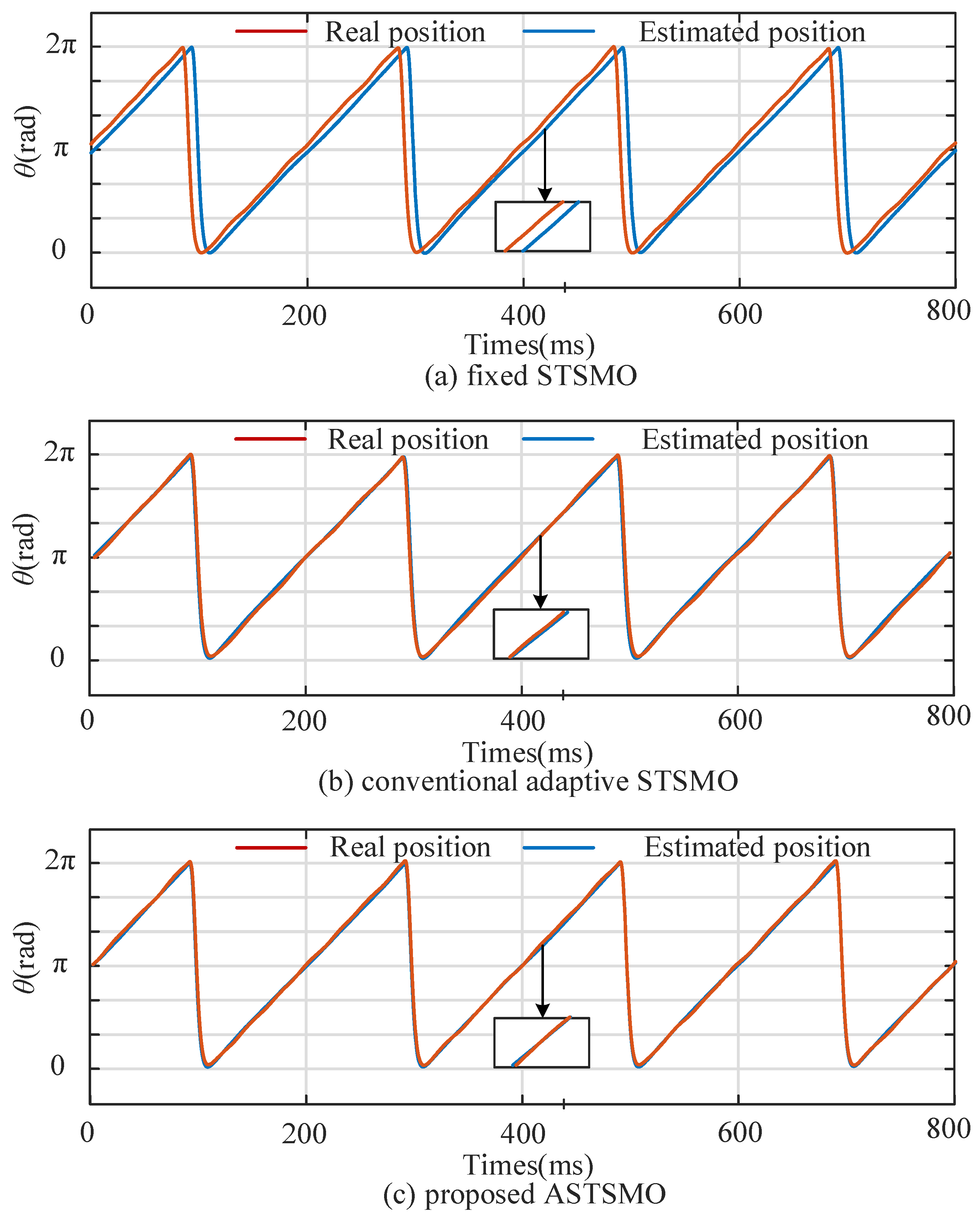
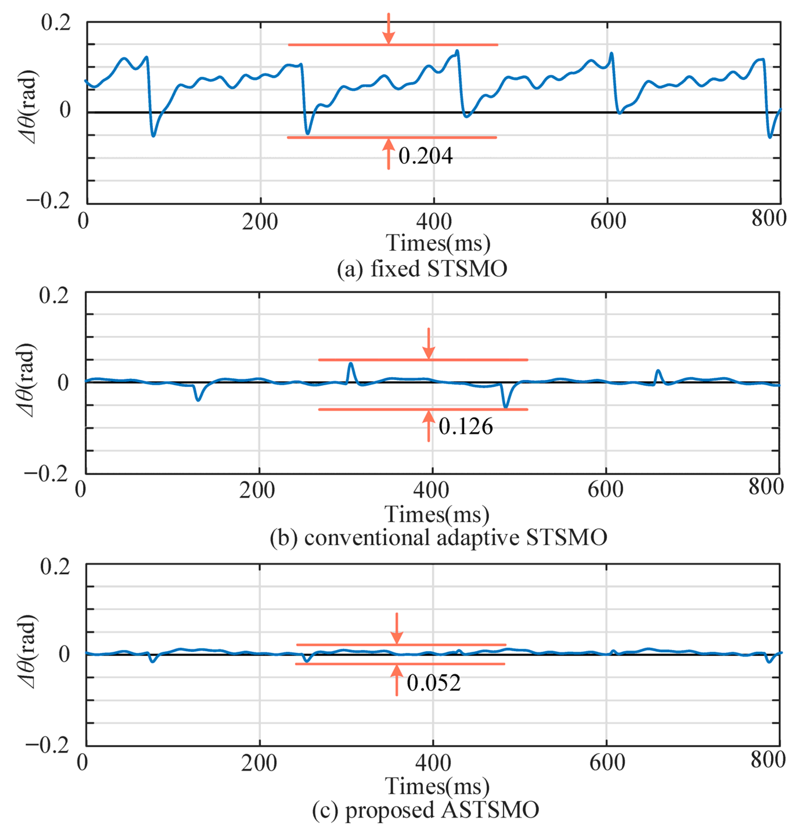
However, when the rotational speed reaches 300 r/min, the position detection accuracy is significantly improved. Figure 9 and Figure 10 show the comparison between the real position and the estimated position under 300 r/min. Figure 11 shows the corresponding position errors. The results indicate that the position estimated by the STSMO has a maximum error of 0.204 rad. On the contrary, the position estimated by the conventional adaptive STSMO has a lower error within 0.126 rad, and its standard deviation is about 0.0392. The position estimated by the proposed ASTSMO has the lowest error within 0.052 rad, and its standard deviation is about 0.0207. The accuracy of the estimated position is improved using the proposed ASTSMO.
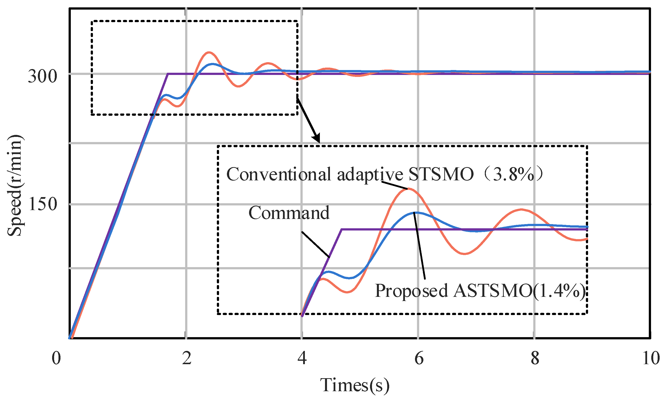
Apart from the static performance, the dynamic performance of the conventional adaptive STSMO and the proposed ASTSMO is also compared. Figure 11 shows the speed responses to a ramp speed command of 0 to 300 r/min. The overshoot of the conventional adaptive STSMO is 3.8%, while the overshoot of the proposed ASTSMO is 1.4%. The adjusting time of the proposed ASTSMO is also much shorter. According to the results, the proposed ASTSMO has a better tracking ability than the conventional adaptive STSMO.
At low speed, according to the conventional adaptive law in (11), the coefficients of the conventional adaptive STSMO are adjusted to very small values, which may influence the tracking speed. By contrast, the coefficient K3 of the proposed ASTSMO has a large enough value related to the stator resistance R, according to the proposed adaptive law in (36). The experimental results also indicate that the PMSM has a better performance at low speed employing the proposed ASTSMO.

4.3. Experiment with Motor Parameters Variation

When the motor parameters are varied, the reliability of the proposed method is also verified. Since it is difficult to accurately change the real motor parameters of the test motor, the motor parameters used in the control model are changed instead. The rotor speed stabilizes at 300 r/min. Table 2 shows the position error when the stator inductance is changed. Table 3 shows the position error when the stator resistance is changed. It can be seen that when the motor parameters used in the model deviate from their real values, the error of the conventional ASTSMO increases, while the error of the proposed ASTSMO changes little.

4.4. Experiment with Motor Speed Variation

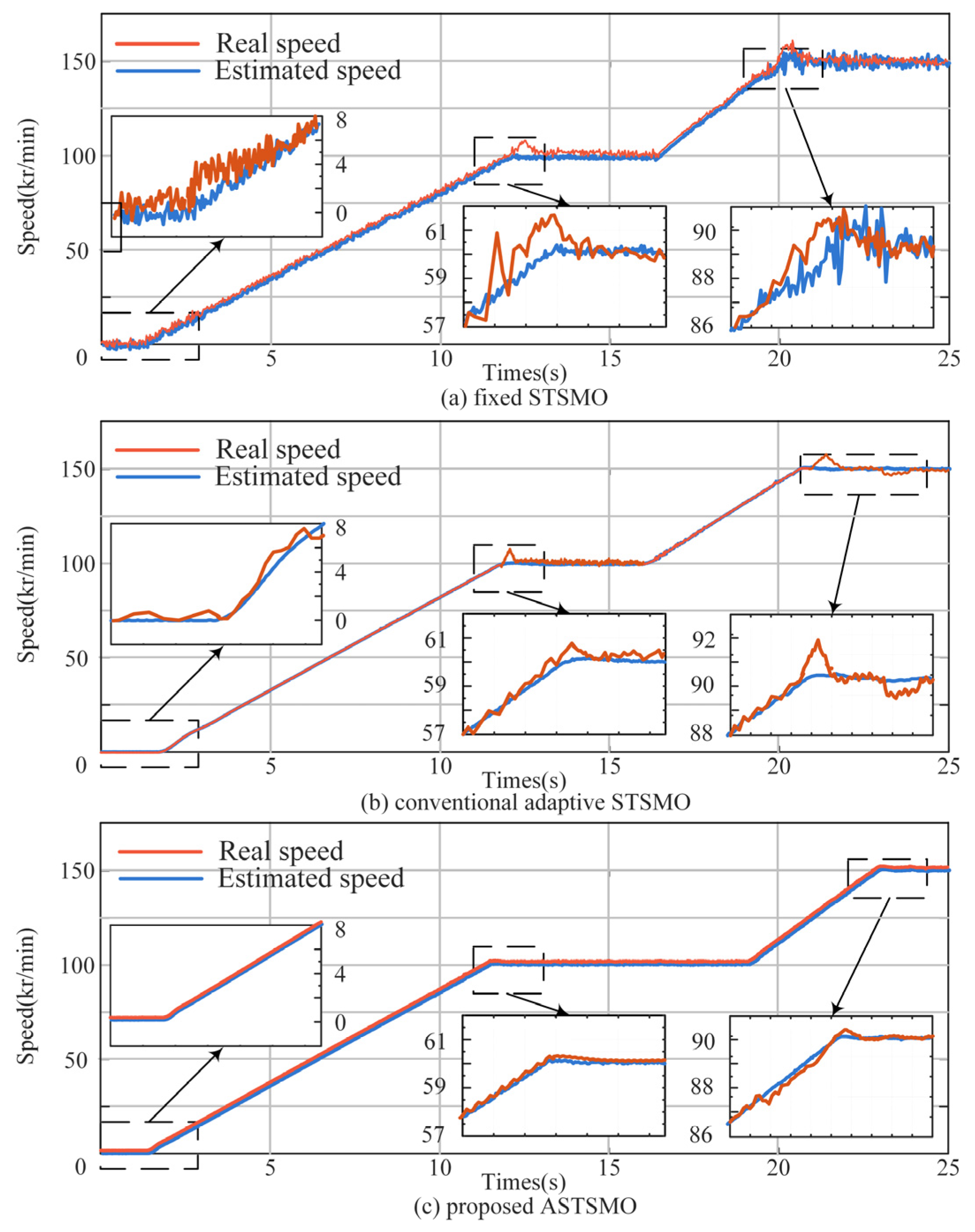
Experiments under acceleration conditions are conducted with the fixed STSMO, the conventional adaptive STSMO, and the proposed ASTSMO separately. Figure 12a–c show the experiment results of the speed accelerated from 0 to 100 kr/min and then to 150 kr/min. The speed estimated by the fixed STSMO has an apparent chattering phenomenon. In contrast, the speeds estimated by the conventional adaptive STSMO and the proposed ASTSMO are smoother.

4.5. Experiment with Torque Current Variation

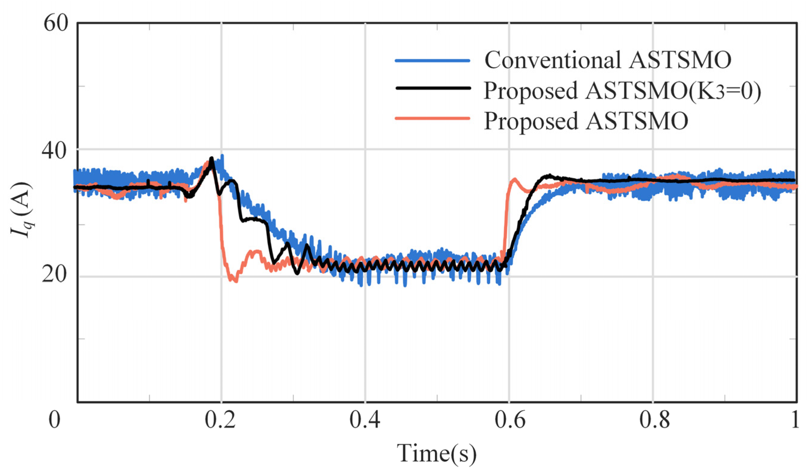
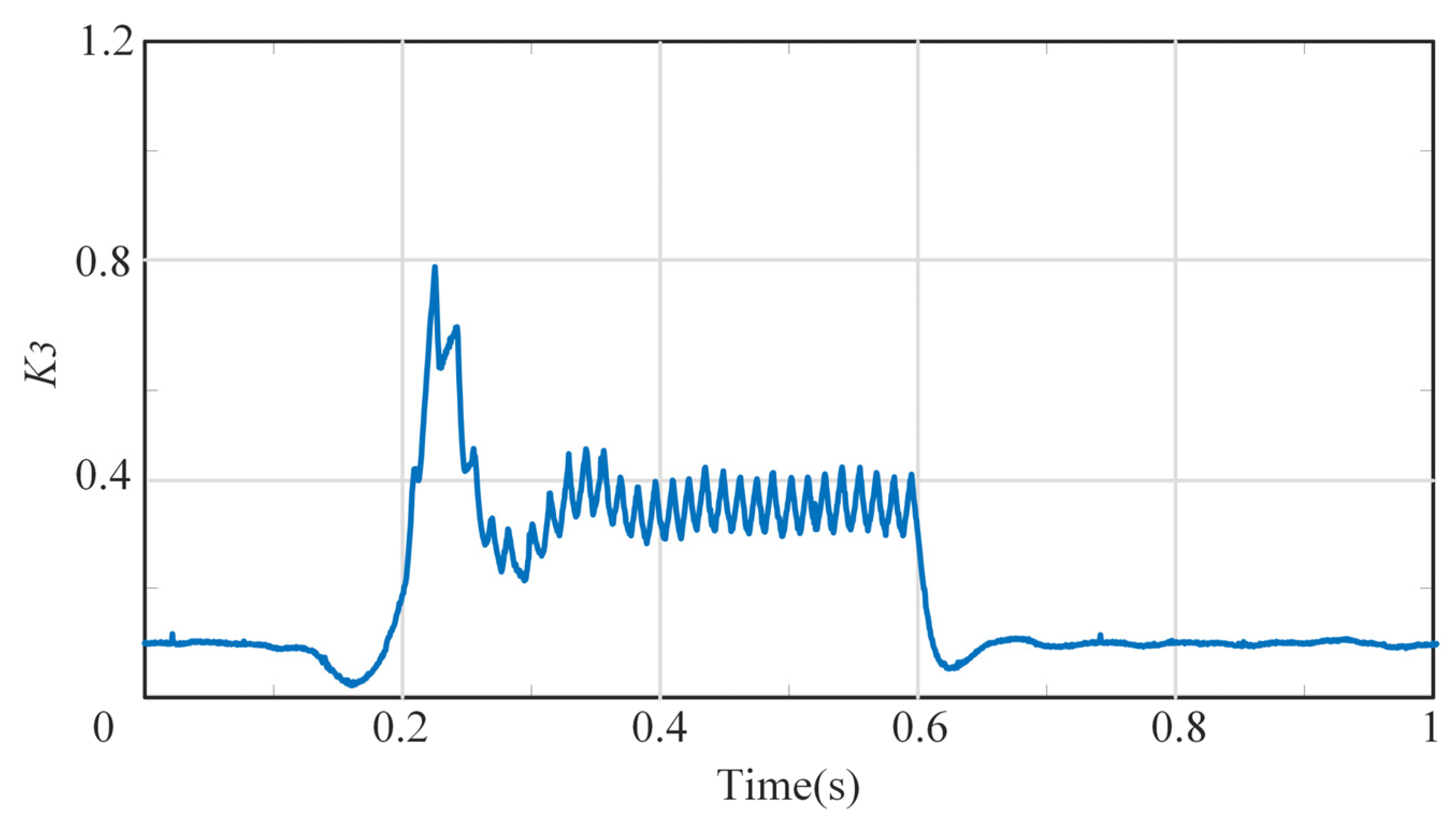
Additionally, an experiment is conducted by keeping the motor speed at 100 kr/min while changing the load from 100% to 50% at 0.2 s and from 50% to 100% at 0.6 s. The ordinate of Figure 12 represents the current in the q-axis, which is the torque current of the PMSM using the Id = 0 control method. The experiment was carried out using the following three methods, respectively: the conventional ASTSMO, the proposed ASTSMO with K3 = 0, and the proposed ASTSMO with the adaptive value of K3. The results are shown in Figure 13. When K3 = 0, the adjusting time of the proposed ASTSMO is about 0.2 s, which is almost the same as that of the conventional ASTSMO. In contrast, when the adaptive value of K3 is adopted to the proposed ASTSMO, the adjusting time was reduced to 0.08 s. The results indicate that the linear correction term can help improve the convergence speed against the sudden current change. According to Figure 13, when the linear compensation is not used (K3 = 0), the response time under disturbance conditions is much longer than that when the linear compensation is used. It can be concluded that the linear compensation can better maintain the stability of the CHC when a sudden disturbance occurs. Figure 14 shows the variation in the parameter K3 during current adjustment.

4.6. Test of CHC

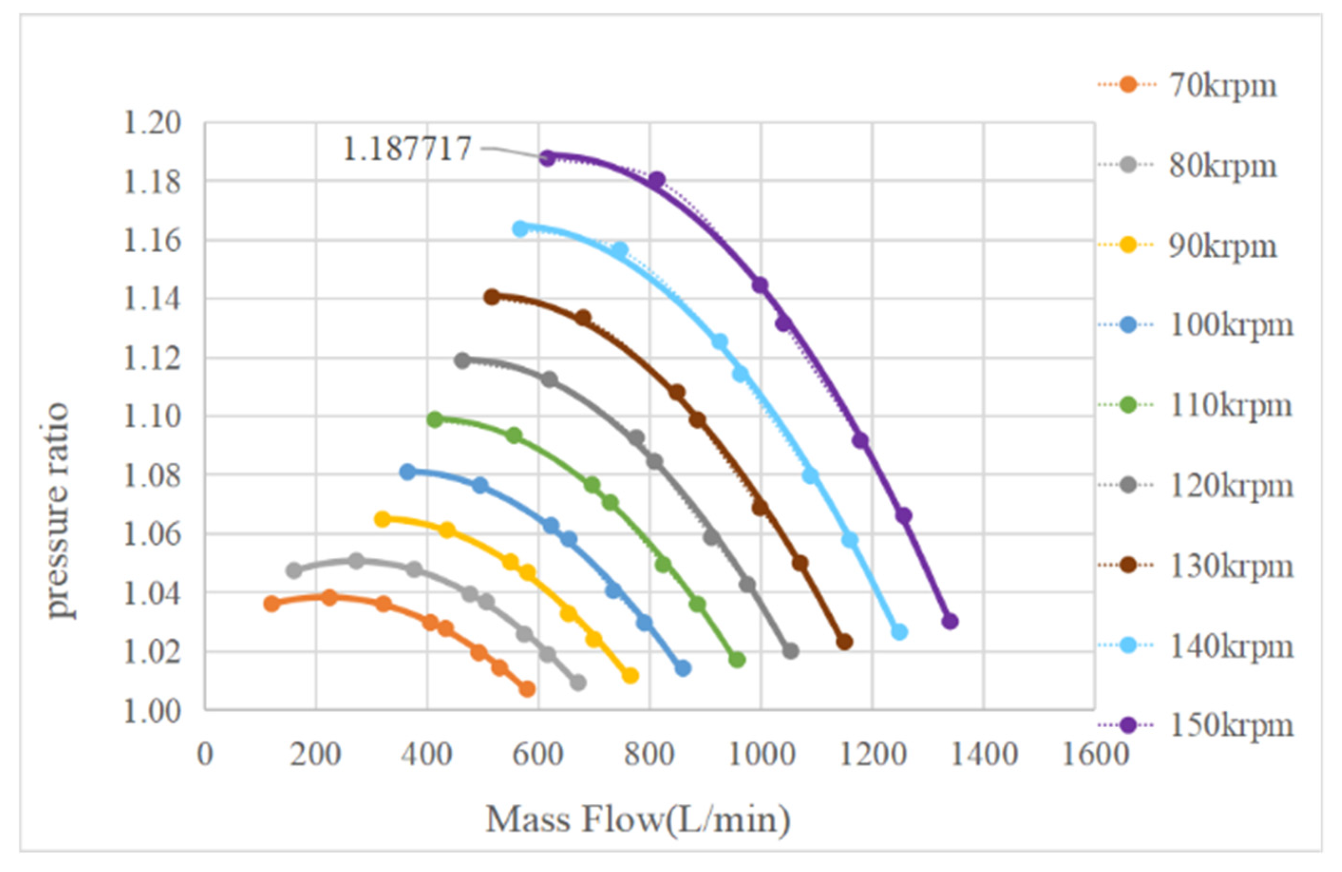
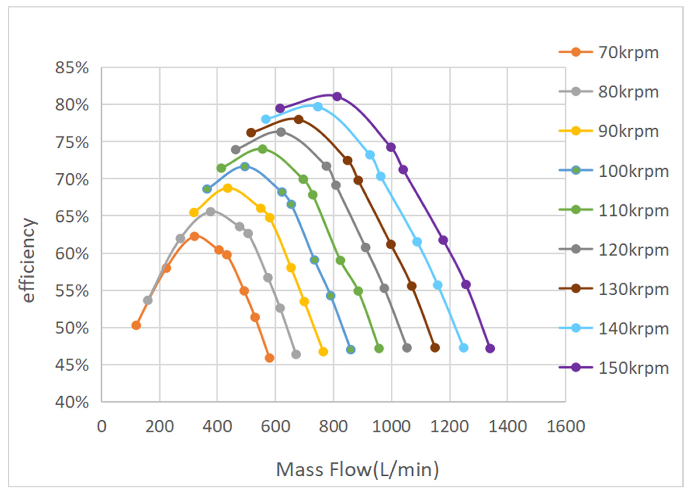
The overall performance of the CHC equipped with the ASTSMO-based PMSM control strategy is also evaluated. The impeller operation speed ranges from 70 kr/min to 150 kr/min. The inlet pressure is 50 kPa and the environment temperature is 25 °C. Figure 15 shows that the maximum pressure ratio can reach 1.18 and the maximum flow is over 1300 L/min. Figure 16 shows that the maximum efficiency of the CHC system is 81%. The solid lines refer to the trend of the pressure ratio and flow change within its work range at each speed. The results indicate that the CHC adopted with the proposed novel ASTSMO can work stably over wide ranges of speed and load. In addition, the proposed scheme shows excellent dynamic performance and high efficiency, demonstrating its dependability and broad availability.

5. Conclusions

This paper adopts a novel ASTSMO to optimize the sensorless control of a highspeed PMSM. According to the specialty of the highspeed PMSM, the coefficient adaptive law based on the change of motor speed, resistance, and current variation is designed. The experimental results show that this scheme effectively suppresses system chattering, and has high accuracy in the estimation of rotor position in the range from low speed to high speed. Additionally, it has fast tracking convergence speed under load disturbance for the highspeed PMSM. The high-order SMO used in this article is based on the super-twisting algorithm, which can simultaneously converge the sliding mode variable and its derivatives to 0 without requiring additional calculations. Therefore, the computation time is much shorter than that of the other kinds of high-order SMOs.
In the performance test of the CHC adopted with the proposed scheme, the gas circulation system shows a fast dynamic response and high efficiency. Its effectiveness is proven and its future is promising.

Author Contributions

Conceptualization, C.Z. and K.M.; methodology, C.Z. and K.M.; software, C.Z.; validation, C.Z.; resources, S.Z.; data curation, C.Z.; writing—original draft preparation, C.Z.; writing—review and editing, S.Z., C.Z. and K.M.; supervision, S.Z. and K.M.; project administration, S.Z. and K.M.; funding acquisition, S.Z. All authors have read and agreed to the published version of the manuscript.

Funding

This research was funded by the National Natural Science Foundation of China under Grant 62225301.

Data Availability Statement

Data used to support the findings of this study are included within this article.

Conflicts of Interest

The authors declare no conflicts of interest.

Abbreviations

The following abbreviations are used in this manuscript:
PMSMPermanent magnetic synchronous motor
CHCCentrifugal hydrogen compressor
ASTSMOAdaptive super-twisting sliding mode observer
STASuper-twisting algorithm
SMOSliding mode observer
FOCField orient control
PLLPhase-lock loop
STSMOSuper-twisting sliding mode observer

References

  1. Peng, Q.; Bao, R.; Li, J.; Ren, J.; Tang, J.; Li, J.; Pan, Z.; Ma, G.; Gao, Y.; Kang, T.; et al. Centrifugal compressor performance prediction and dynamic simulation of natural gas hydrogen blended. Int. J. Hydrogen Energy 2024, 52, 872–893. [Google Scholar] [CrossRef]
  2. Singh, U.R.; Bhogilla, S. A self-sustaining renewable energy driven hydrogen refuelling system utilising a metal hydride-based compressor. Int. J. Hydrogen Energy 2024, 52, 1419–1433. [Google Scholar] [CrossRef]
  3. Ye, J.; He, Y.; Du, Z.; Ji, R.; Xie, J.; Liu, J. The transient flow and heat transfer characteristics in reciprocated conditions of hydraulic-driven piston hydrogen compressor in hydrogen storage system. J. Energy Storage 2024, 89, 111662. [Google Scholar] [CrossRef]
  4. Khan, A.; Irfan, M.; Niazi, U.M.; Shah, I.; Legutko, S.; Rahman, S.; Alwadie, A.S.; Jalalah, M.; Glowacz, A.; Khan, M.K.A. Centrifugal Compressor Stall Control by the Application of Engineered Surface Roughness on Diffuser Shroud Using Numerical Simulations. Materials 2021, 14, 2033. [Google Scholar] [CrossRef]
  5. Dong, L.; Jiang, P. Improved super-twisting sliding mode control strategy in permanent magnet synchronous motors for hydrogen fuel cell centrifugal compressor. Heliyon 2024, 10, e24181. [Google Scholar] [CrossRef]
  6. Yu, Y.; Tu, Z.; Zhang, H.; Zhan, Z.; Pan, M. Comparison of degradation behaviors for open-ended and closed proton exchange membrane fuel cells during startup and shutdown cycles. J. Power Sources 2011, 196, 5077–5083. [Google Scholar] [CrossRef]
  7. Bacak, A.; Pınarbaşı, A.; Dalkılıç, A.S. A 3-D FSI simulation for the performance prediction and valve dynamic analysis of a hermetic reciprocating compressor. Int. J. Refrig. 2023, 150, 135–148. [Google Scholar] [CrossRef]
  8. Guo, X.; Hu, X.; Zhang, S. Application status of variable-frequency drive in hydrogen fuel cell air compressors from an industrial viewpoint: A review. Sustain. Energy Technol. Assess. 2024, 64, 103716. [Google Scholar] [CrossRef]
  9. Liu, G.; Zhao, Y.; Tang, B.; Li, L. Dynamic performance of suction valve in stepless capacity regulation system for large-scale reciprocating compressor. Appl. Therm. Eng. 2016, 96, 167–177. [Google Scholar] [CrossRef]
  10. Wu, Y.; Bao, H.; Fu, J.; Wang, X.; Liu, J. Review of recent developments in fuel cell centrifugal air compressor: Comprehensive performance and testing techniques. Int. J. Hydrogen Energy 2023, 48, 32039–32055. [Google Scholar] [CrossRef]
  11. Hou, J.; Yang, M.; Ke, C.; Zhang, J. Control logics and strategies for air supply in PEM fuel cell engines. Appl. Energy 2020, 269, 115059. [Google Scholar] [CrossRef]
  12. Gao, D.; Jin, Z.; Zhang, J.; Li, J.; Ouyang, M. Development and performance analysis of a hybrid fuel cell/battery bus with an axle integrated electric motor drive system. Int. J. Hydrogen Energy 2016, 41, 1161–1169. [Google Scholar] [CrossRef]
  13. Wang, K.; Yan, Y.; Mao, K.; Zheng, S.; Hao, M.; Zhang, Y. Adaptive current decoupling control scheme based on online multi-parameter identification for high-speed permanent magnet synchronous motor in fuel cell. Int. J. Hydrogen Energy 2024, 86, 542–553. [Google Scholar] [CrossRef]
  14. Jiang, Y.; Cheng, M. An improved initial rotor position estimation method using high-frequency pulsating voltage injection for PMSM. Def. Technol. 2024, 33, 19–29. [Google Scholar] [CrossRef]
  15. Chi, X.; Wang, C.; Wu, Q.; Yang, J.; Lin, W.; Zeng, P.; Li, H.; Shao, M. A ripple suppression of sensorless FOC of PMSM electrical drive system based on MRAS. Results Eng. 2023, 20, 101427. [Google Scholar] [CrossRef]
  16. Dan, L. EKF-based fault detection and isolation for PMSM inverter. Sustain. Energy Technol. Assess. 2022, 52, 101846. [Google Scholar] [CrossRef]
  17. Li, Y.; Wang, D.; Zhou, S. Moment of inertia identification for PMSM based on extended SMO and improved RBFNN. Energy Rep. 2023, 9, 521–528. [Google Scholar] [CrossRef]
  18. Zuo, Y.; Lai, C.; Iyer, K.L.V. A Review of Sliding Mode Observer Based Sensorless Control Methods for PMSM Drive. IEEE Trans. Power Electron. 2023, 38, 11352–11367. [Google Scholar] [CrossRef]
  19. Hou, Q.; Ding, S. Finite-Time Extended State Observer-Based Super-Twisting Sliding Mode Controller for PMSM Drives with Inertia Identification. IEEE Trans. Transp. Electrif. 2022, 8, 1918–1929. [Google Scholar] [CrossRef]
  20. Xu, W.; Cheng, S.; Ge, J.; Zhou, M.; Liao, K.; Wang, A.; Qu, G. Improved Adaptive Terminal Sliding-Mode Reaching Law for Speed Control of TPMLSM with Disturbance Observer. IEEE Trans. Ind. Appl. 2023, 59, 3210–3219. [Google Scholar] [CrossRef]
  21. Gong, C.; Hu, Y.; Gao, J.; Wang, Y.; Yan, L. An Improved Delay-Suppressed Sliding-Mode Observer for Sensorless Vector-Controlled PMSM. IEEE Trans. Ind. Electron. 2020, 67, 5913–5923. [Google Scholar] [CrossRef]
  22. An, Q.; Zhang, J.; An, Q.; Liu, X.; Shamekov, A.; Bi, K. Frequency-Adaptive Complex-Coefficient Filter-Based Enhanced Sliding Mode Observer for Sensorless Control of Permanent Magnet Synchronous Motor Drives. IEEE Trans. Ind. Appl. 2020, 56, 335–343. [Google Scholar] [CrossRef]
  23. Liu, G.; Zhang, H.; Song, X. Position-Estimation Deviation-Suppression Technology of PMSM Combining Phase Self-Compensation SMO and Feed-Forward PLL. IEEE J. Emerg. Sel. Top. Power Electron. 2021, 9, 335–344. [Google Scholar] [CrossRef]
  24. Song, X.; Fang, J.; Han, B.; Zheng, S. Adaptive Compensation Method for High-Speed Surface PMSM Sensorless Drives of EMF-Based Position Estimation Error. IEEE Trans. Power Electron. 2016, 31, 1438–1449. [Google Scholar] [CrossRef]
  25. Li, S.; Xu, Y.; Zhang, W.; Zou, J. Robust Deadbeat Predictive Direct Speed Control for PMSM with Dual Second-Order Sliding-Mode Disturbance Observers and Sensitivity Analysis. IEEE Trans. Power Electron. 2023, 38, 8310–8326. [Google Scholar] [CrossRef]
  26. Liu, Y.-C.; Laghrouche, S.; Depernet, D.; Djerdir, A.; Cirrincione, M. Disturbance-Observer-Based Complementary Sliding-Mode Speed Control for PMSM Drives: A Super-Twisting Sliding-Mode Observer-Based Approach. IEEE J. Emerg. Sel. Top. Power Electron. 2021, 9, 5416–5428. [Google Scholar] [CrossRef]
  27. Sun, Y.; Yang, M.; Wang, B.; Chen, Y.; Xu, D. Precise Position Control Based on Resonant Controller and Second-Order Sliding Mode Observer for PMSM-Driven Feed Servo System. IEEE Trans. Transp. Electrif. 2023, 9, 196–209. [Google Scholar] [CrossRef]
  28. Lian, C.; Xiao, F.; Gao, S.; Liu, J. Load Torque and Moment of Inertia Identification for Permanent Magnet Synchronous Motor Drives Based on Sliding Mode Observer. IEEE Trans. Power Electron. 2019, 34, 5675–5683. [Google Scholar] [CrossRef]
  29. Wang, Y.; Xu, Y.; Zou, J. Sliding-Mode Sensorless Control of PMSM with Inverter Nonlinearity Compensation. IEEE Trans. Power Electron. 2019, 34, 10206–10220. [Google Scholar] [CrossRef]
  30. Morales, D.B.; Delpoux, R.; Lechappe, V.; Morales, J.D.L. Single-Gain Super-Twisting Algorithm Application to PMSM. IEEE J. Emerg. Sel. Top. Ind. Electron. 2021, 2, 237–246. [Google Scholar] [CrossRef]
  31. Sreejith, R.; Singh, B. Sensorless Predictive Control of SPMSM-Driven Light EV Drive Using Modified Speed Adaptive Super Twisting Sliding Mode Observer with MAF-PLL. IEEE J. Emerg. Sel. Top. Ind. Electron. 2021, 2, 42–52. [Google Scholar] [CrossRef]
  32. Liang, D.; Li, J.; Qu, R. Sensorless Control of Permanent Magnet Synchronous Machine Based on Second-Order Sliding-Mode Observer with Online Resistance Estimation. IEEE Trans. Ind. Appl. 2017, 53, 3672–3682. [Google Scholar] [CrossRef]
  33. Liang, D.; Li, J.; Qu, R.; Kong, W. Adaptive Second-Order Sliding-Mode Observer for PMSM Sensorless Control Considering VSI Nonlinearity. IEEE Trans. Power Electron. 2018, 33, 8994–9004. [Google Scholar] [CrossRef]
  34. Ding, L.; Li, Y.W.; Zargari, N.R. Discrete-Time SMO Sensorless Control of Current Source Converter-Fed PMSM Drives with Low Switching Frequency. IEEE Trans. Ind. Electron. 2021, 68, 2120–2129. [Google Scholar] [CrossRef]
  35. An, Q.; Zhang, J.; An, Q.; Shamekov, A. Quasi-Proportional-Resonant Controller Based Adaptive Position Observer for Sensorless Control of PMSM Drives Under Low Carrier Ratio. IEEE Trans. Ind. Electron. 2020, 67, 2564–2573. [Google Scholar] [CrossRef]
  36. Moreno, J.A.; Osorio, M. A Lyapunov approach to second-order sliding mode controllers and observers. In Proceedings of the 2008 47th IEEE Conference on Decision and Control, Cancun, Mexico, 9–11 December 2008; pp. 2856–2861. [Google Scholar]
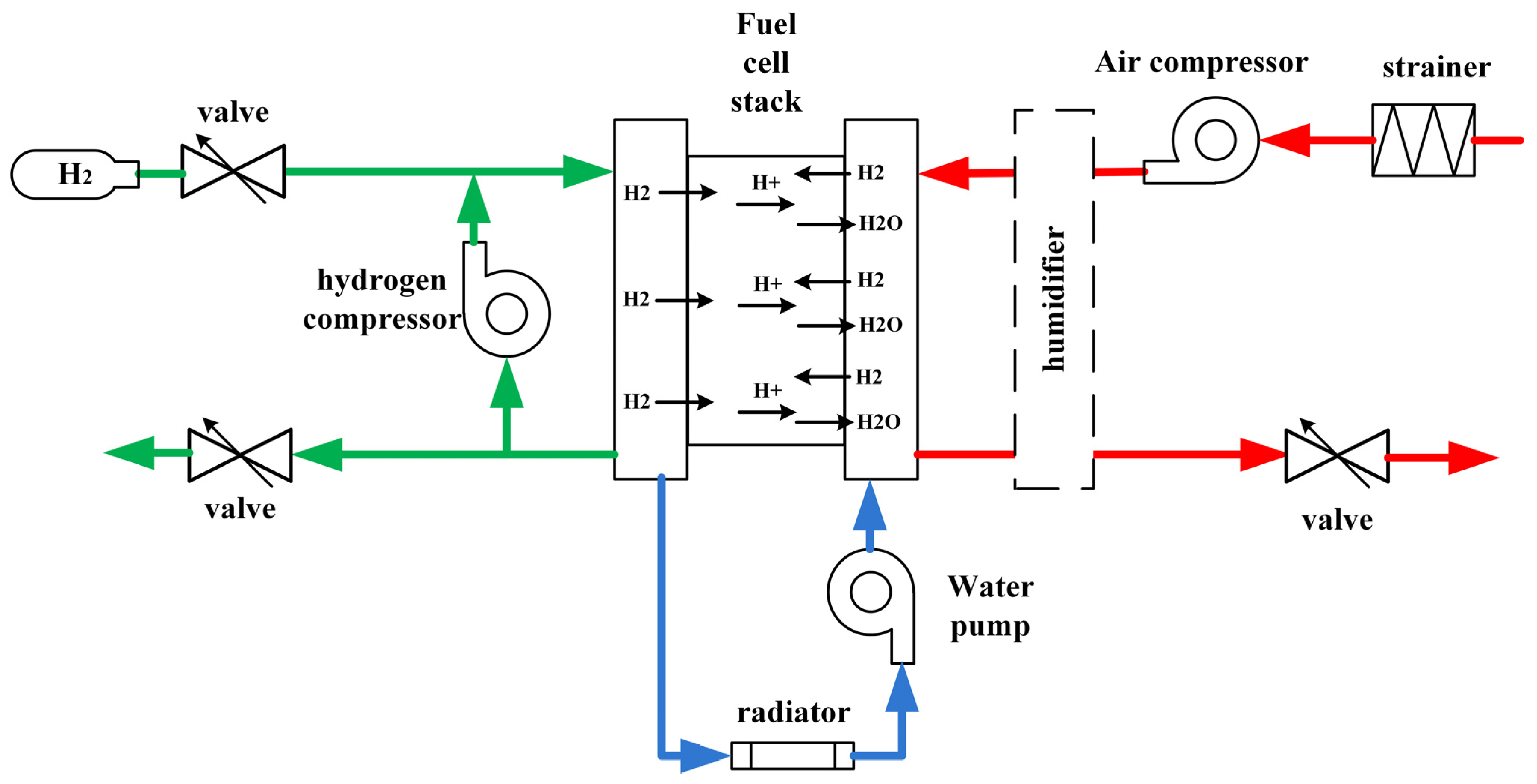
Figure 1. Hydrogen fuel cell power system.
Energies 18 04675 g001
Figure 2. FOC strategy.
Energies 18 04675 g002
Figure 3. Model of the discrete ASTSMO.
Energies 18 04675 g003
Figure 4. Sensorless strategy for the PMSM on the ASTSMO.
Energies 18 04675 g004
Figure 5. Gas circulation platform.
Energies 18 04675 g005
Figure 6. Control circuit.
Energies 18 04675 g006
Figure 7. Simulation results.
Energies 18 04675 g007
Figure 8. Rotor positions of the tested PMSM at 60 r/min.
Energies 18 04675 g008
Figure 9. Rotor positions of the tested PMSM at 300 r/min.
Energies 18 04675 g009
Figure 10. Position errors of the tested PMSM at 300 r/min.
Energies 18 04675 g010
Figure 11. Experiment results of the speed command to 300 r/min.
Energies 18 04675 g011
Figure 12. Speed comparison under acceleration conditions from standstill to 150 kr/min.
Energies 18 04675 g012
Figure 13. Current comparison under disturbance conditions.
Energies 18 04675 g013
Figure 14. Variation in K3 during current adjustment.
Energies 18 04675 g014
Figure 15. Pressure ratio and flow test results of the CHC.
Energies 18 04675 g015
Figure 16. Efficiency of the CHC.
Energies 18 04675 g016
Table 1. The parameters of the PMSM.
CoefficientValueUnit
Stator resistance Rs17
Stator inductance Ls12μH
Pole pairs P1
Rated speed ω0150kr/min
Flux linkage ψf0.175Wb
Inertia J0.001kg·m2
Table 2. Position error with inductance change.
Inductance (μH)91215
Conventional ASTSMO0.183 rad0.126 rad0.178 rad
Proposed ASTSMO0.057 rad0.052 rad0.055 rad
K11.1251.51.875
K2150200250
Table 3. Position error with resistance change.
Resistance (mΩ)121722
Conventional ASTSMO0.183 rad0.126 rad0.178 rad
Proposed ASTSMO0.057 rad0.052 rad0.055 rad
Disclaimer/Publisher’s Note: The statements, opinions and data contained in all publications are solely those of the individual author(s) and contributor(s) and not of MDPI and/or the editor(s). MDPI and/or the editor(s) disclaim responsibility for any injury to people or property resulting from any ideas, methods, instructions or products referred to in the content.