Abstract
Axial flux motors, characterized by compact axial dimensions and high torque density, are well-suited for space-constrained applications such as in-wheel drives and flying vehicles. However, conventional axial flux permanent magnet synchronous motors (AFPMSMs) face challenges such as high-temperature demagnetization, reduced efficiency at high speeds, and elevated manufacturing costs. Electrically excited synchronous motors (EESMs) offer a promising alternative, providing high-temperature reliability and superior high-speed capability while maintaining high torque density. In this paper, a novel composite-cooled axial flux electrically excited synchronous motor (AFEESM) is proposed. From an electromagnetic design perspective, the effects of key parameters such as shaft-to-outer-diameter ratio, inner-to-outer-diameter ratio, slot depth, and yoke thickness on output performance are systematically investigated, and a dedicated design procedure is established. Through multi-objective optimization, the motor’s torque output is increased by 19.6%. Comparative simulations are conducted to evaluate differences in torque density, efficiency, and cost between the proposed AFEESM, a conventional radial flux EESM, and an AFPMSM. To address the cooling requirements of double-sided windings on both the stator and rotor, a dual-channel composite cooling structure is developed, integrating internal–external double-loop water cooling for the stator and axial through-hole air cooling for the rotor, reducing the peak temperature by over 36%. Finally, a prototype is manufactured, and no-load characteristics and load efficiency validate the effectiveness of the electromagnetic design and the structural reliability of the motor.
1. Introduction
Applications with stringent spatial constraints, such as flying cars and direct-drive electric vertical take-off and landing vehicles, require an electric motor with a high torque density. Compared with conventional radial flux motors, axial flux motors feature a more compact structure and, owing to their shorter magnetic flux path and larger effective air-gap surface area, can deliver higher torque within the same overall volume. Consequently, they are regarded as one of the most promising motor technologies [1,2].
Managing thermal rise under compact packaging and high-torque-density conditions remains a critical challenge. Most existing axial flux machines are permanent magnet types, which are prone to irreversible demagnetization under elevated temperatures. Furthermore, the high cost of rare-earth materials, reduced efficiency at high speeds, and power degradation limit the widespread adoption of axial flux motors in applications such as flying vehicles.
EESMs offer superior high-speed capability, immunity to demagnetization, and cost effectiveness due to the controllability of field excitation. Additionally, the large inner diameter inherent to axial flux machines enables the seamless integration of the excitation system, effectively mitigating brush-related issues. As a result, axial flux electrically excited machines exhibit significant potential for advanced applications and further development [3,4,5]. This paper proposes a novel composite-cooled AFEESM with electromagnetic parameter design theory and dual-sided composite cooling for the stator and rotor, aiming to improve the motor’s output performance and torque density.
In 1980, researchers from the University of Hong Kong proposed a novel design and manufacturing method for a sandwich-type axial field motor [6]. Since then, axial flux machines have been widely investigated, with most studies focusing on PM topologies. Research on AFEESMs primarily addresses aspects such as structure, materials, and performance enhancement. References [7,8,9] sequentially optimized air gap and turn parameters and studied the constraints between torque density, axial force, and air-gap length. Reference [10] explored the potential application of high-temperature superconducting materials in axial flux motors. Overall, AFEESMs are still in their nascent stage. The design principles governing the relationship between electromagnetic performance and key geometric parameters remain unclear. Furthermore, the comparative analysis of AFEESMs against axial flux PM machines and radial flux EESMs is insufficient, and their potential advantages are yet to be fully elucidated.
Owing to the compact axial topology, managing temperature rise in axial flux motors is a critical constraint. Moreover, with the simultaneous presence of heat sources from both-sided windings, an efficient cooling system is even more crucial for AFEESMs. Current work centers on air and liquid cooling. References [11,12] investigated the cooling performance at different speeds by adding fan blades and ventilation holes to the rotor back and yoke. In liquid cooling, the coolant channels are typically located at the casing/end-cover areas [13]. Reference [14] compared four types of end-cap cooling structures and found that the series-connected water channel delivered the best cooling performance. Reference [15] proposed a dual-cooling scheme combining a spiral water channel in the housing with an axial U-shaped water pipe, achieving a 38% increase in motor power density. References [16,17,18,19] effectively cooled the winding ends through oil injection holes and oil channel design, thereby improving power and torque density. Overall, the current research on axial flux motor cooling has primarily targeted PM topologies. Given the loss distribution in dual-sided windings of AFEESMs, simultaneous management of stator and rotor thermal loads is required; a single-mode strategy is unlikely to meet the elevated heat-flux demands.
In summary, this paper presents a high-torque-density AFEESM with a composite cooling system. Section 2 presents the system topology and introduces the key parameter design method and procedure for the novel motor. Section 3 conducts multi-objective optimization and performance simulations. Section 4 details the development of an integrated stator–rotor composite cooling structure combining water and air cooling. Section 5 describes the prototype fabrication and experimental validation. Conclusions are drawn in Section 6.
2. Motor Topology and Parameter Influence Mechanism
2.1. Optimal Topology Selection
Axial flux machines offer flexible stator–rotor configurations to meet diverse application requirements. Typical topologies include single-stator single-rotor (SSSR), single-stator double-rotor (SSDR), and double-stator single-rotor (DSSR), as illustrated in Figure 1a–c, respectively. Among these, the NS-type SSDR can be extended to the YASA-type topology, as shown in Figure 1d. The corresponding no-load flux paths are also depicted. By eliminating the stator yoke and employing fractional-slot concentrated windings, each coil can be pre-wound on individual teeth, enabling modular manufacturing. Moreover, independent winding facilitates more efficient space utilization, thereby increasing the slot fill factor, improving efficiency, and enhancing torque density.
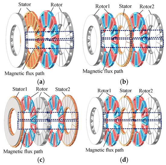
Figure 1.
Motor models with different topologies: (a) SSSR structure; (b) SSDR structure; (c) DSSR structure; (d) YASA structure.
To identify the optimal topology, a comparative analysis was performed across multiple configurations under uniform conditions: a current density of 5 A/mm2, identical core outer dimensions, and equal axial lengths for the stator, rotor, and air gap. The design parameters and corresponding performance metrics are summarized in Table 1. The results show that while the SSSR topology yields the highest torque density, it exhibits significant unbalanced magnetic pull, which restricts its practical applicability. In contrast, the YASA topology offers both high efficiency and high torque density, making it more suitable for the target application in this study.

Table 1.
Structures and performance of motors with different topologies.
Given the unique characteristics of the AFEESM, including its multi-dimensional stator and rotor combinations, flat structure, and double-sided winding excitation, particular attention must be paid to the corresponding pole–slot combination, axial length-to-diameter ratio, and spatial allocation between stator and rotor in its design. To determine the motor’s optimal structure, this section investigates the influence of key parameters on motor performance and presents the design method and procedure for this type of motor.
2.2. Mechanism of Parameter Influence
2.2.1. Pole–Slot Combination
In the design of an axial flux motor, the pole–slot combination directly affects the space harmonic content and the fundamental winding factor, thereby influencing the torque density. Elevated space harmonics can introduce parasitic effects, leading to increased torque ripple, electromagnetic noise, and reduced efficiency.
The torque equation of the axial flux motor can be expressed as
In conjunction with the characteristics of the AFEESM rotor, the torque density (Nm/L) can be expressed as follows:
From Equation (2), it can be seen that, assuming a constant current density and neglecting magnetic saturation, a smaller pole number and slot number lead to a higher torque density.
To quantitatively determine the pole–slot combination, the structural parameters listed in Table 2 are adopted as a case study, referencing the YASA 750R series design concept to illustrate the underlying design principles.

Table 2.
Example parameters of axial flux electrically excited motor.
Table 3 summarizes typical slot–pole number combinations for axial flux motors. When the fundamental winding factor exceeds 0.9, a larger slot per pole per phase value is preferred. Accordingly, three configurations—16-pole 18-slot, 20-pole 24-slot, and 24-pole 27-slot—are selected for comparative analysis. The corresponding output characteristics are presented in Table 4. Among these, the 20-pole 24-slot configuration offers a favorable trade-off between torque density and efficiency and is therefore adopted as the optimal choice in this study.

Table 3.
Winding factors for different pole–slot combinations.

Table 4.
Motor performance under different pole–slot combinations.
2.2.2. Inner and Outer Diameter Ratio and Shaft Diameter Ratio
For the planar structure of an axial flux motor, both the shaft-to-outer-diameter ratio and the inner-to-outer-diameter ratio are critical, as they jointly influence magnetic field distribution, energy conversion efficiency, and manufacturing cost.
Figure 2 illustrates the key dimensional parameters of the proposed AFEESM. Taking the inner-to-outer-diameter ratio as an example, increasing this ratio reduces winding length and copper losses but also decreases the core volume, thereby weakening the magnetic field. Thus, the optimization of both the shaft-to-outer-diameter ratio and the inner-to-outer-diameter ratio requires a trade-off between electromagnetic and thermal performance. To investigate parameter selection trends, the influence of these ratios on torque density was analyzed for the three previously discussed pole–slot combinations, as shown in Figure 3.
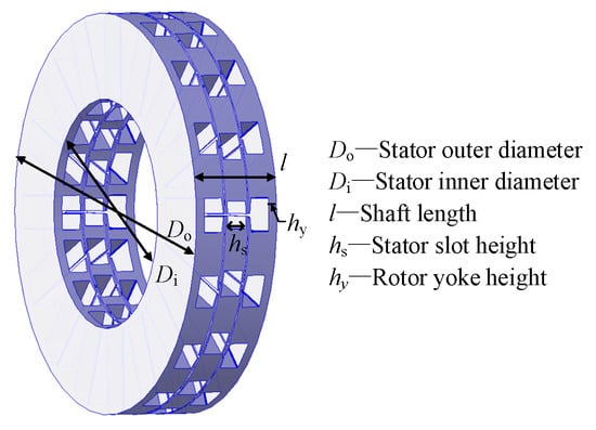
Figure 2.
Motor key parameter schematic diagram.

Figure 3.
Influence of design parameters on torque density under different pole–slot combinations. (a) Influence of inner-to-outer-diameter ratio kd on torque density. (b) Influence of shaft-to-outer-diameter ratio kh on torque density.
It can be seen from the figure that reducing the pole–slot number generally enhances torque output. However, in certain cases, localized magnetic saturation may lead to a reduction in torque. Additionally, as the design adopts a flatter configuration, i.e., with a lower shaft-to-outer-diameter ratio, torque density tends to increase.
As the inner-to-outer-diameter ratio varies, an inflection point is observed where torque density reaches its peak. Further analysis of its effect on efficiency, as shown in Figure 4, reveals an intersection region where torque, torque density, and efficiency are simultaneously optimized. Therefore, the inner-to-outer-diameter ratio should be selected within this interval to achieve a balanced and comprehensive performance.

Figure 4.
Influence of inner-to-outer-diameter ratio kd on motor output performance: (a) torque and torque density; (b) efficiency and core loss.
In summary, given the selected pole–slot configuration, the motor favors a small shaft-to-outer-diameter ratio and a flat profile, both of which enhance torque performance. The inner-to-outer-diameter ratio should be optimized by balancing effective utilization of the core and windings and tailored to the specific operating conditions and performance requirements.
2.2.3. Stator and Rotor Space Allocation
In AFEESMs, both the stator and rotor require excitation winding design. Compared with PM motors, the wound rotor occupies more space. Proper allocation of stator and rotor space is essential for improving core utilization and balancing losses, which is particularly critical for this topology. In this study, the total axial length and air gap length are fixed, while two key design parameters—stator slot depth and rotor yoke thickness—are optimized. Their impacts on torque, efficiency, and loss distribution are illustrated in Figure 5.
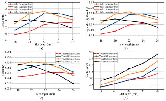
Figure 5.
Influence of stator slot depth and rotor yoke thickness on motor performance: (a) torque; (b) torque density; (c) efficiency; (d) core loss.
As shown in Figure 5a,b, both stator slot depth and rotor yoke thickness exhibit a non-monotonic effect on torque and torque density, with performance increasing initially and then declining. A trade-off exists between the two parameters. Figure 5c,d further show that increasing the stator slot depth reduces the space available for field windings, adversely impacting efficiency. In this scenario, copper loss becomes dominant, particularly when the yoke thickness is excessive. Considering all factors, a parameter combination near the inflection point is chosen, with a stator slot depth of 22 mm and a rotor yoke thickness of 5 mm.
Overall, the performance of the AFEESM is significantly influenced by spatial constraints imposed by double-sided windings and by tooth and yoke dimensions. By properly balancing key parameters such as slot depth and yoke thickness, the coupling between stator and rotor windings and the magnetic core can be effectively managed, enabling an optimized trade-off between torque output and efficiency.
2.2.4. Design Process
Based on the preceding analysis, the design procedure for the proposed AFEESM is illustrated in Figure 6. The first step is to define the performance targets. Then, appropriate electromagnetic loading values are selected according to the motor power equation, and key parameters such as the pole–slot combination, shaft-to-outer-diameter ratio, and inner-to-outer-diameter ratio are determined. Subsequently, yoke dimensions are assigned to establish the stator–rotor spatial configuration, yielding the initial design. A finite element model is developed to evaluate electromagnetic performance, and design parameters are iteratively refined until the specified operating requirements are satisfied.
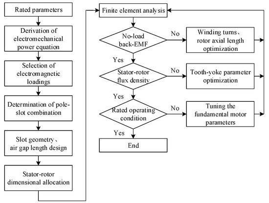
Figure 6.
Motor design flowchart.
3. Motor Optimization and Simulation Analysis
Once the initial structural parameters are defined, finite element-based multi-objective optimization is employed to further enhance motor performance. In this stage, additional design variables, including stator and rotor slot parameters, are introduced. Torque and efficiency are selected as optimization objectives, and an improved multi-objective genetic algorithm is utilized to perform the optimization.
The correlation coefficient matrix is shown in Figure 7a. For average torque, a positive correlation is observed between stator slot depth and rotor yoke thickness. In the efficiency analysis, inner diameter and rotor yoke thickness are identified as key influencing factors, with the inner diameter exhibiting a negative correlation with efficiency. The distribution of the simulation-based optimization results is illustrated in Figure 7b, and a comparison of motor parameters before and after optimization is provided in Table 5.

Figure 7.
Analysis of optimization results: (a) parameter correlation analysis; (b) design point and optimal set.

Table 5.
Values of optimization parameters before and after optimization.
The performance of the initial and optimized designs under peak operating conditions is summarized in Table 6. The results demonstrate a significant torque improvement with only a minor reduction in efficiency.

Table 6.
Comparison before and after optimization.
Based on the optimization parameter values listed in Table 5, a finite element simulation model of the motor was established, as shown in Figure 8. Simulation studies were conducted to verify the feasibility of the motor design principle and the validity of its operating performance indicators.
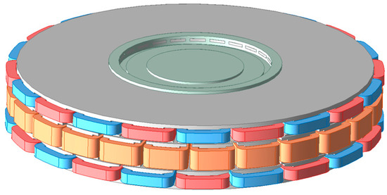
Figure 8.
Schematic diagram of motor structure finite element model.
3.1. No-Load Characteristics
Under the rated operating condition, the no-load back-EMF waveform of AFEESM and its harmonic analysis are shown in Figure 9.

Figure 9.
No-load back EMF waveform of the motor: (a) no-load back EMF; (b) harmonic analysis.
The incorporation of rotor slots for field winding introduces air-gap non-uniformity, resulting in the distortion of the magnetic field distribution. Additionally, the use of concentrated windings increases the harmonic content in the induced EMF.
3.2. Load Characteristics
Under rated three-phase symmetrical AC excitation for the armature winding and rated DC excitation for the field winding, the torque output characteristic is shown in Figure 10. The average electromagnetic torque reaches 86.4 Nm with a torque ripple of 13.32%, satisfying the rated performance requirements. Furthermore, the simulated torque-speed (T-n) and power-speed (P-n) characteristics are shown in Figure 11. The corner speed is approximately 2600 r/min. The motor exhibits minimal power drop-off during speed escalation and maintains a high power output even at nearly triple the base speed.
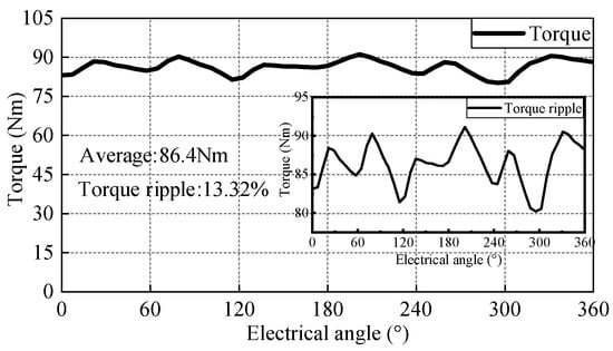
Figure 10.
Electromagnetic torque output characteristics.
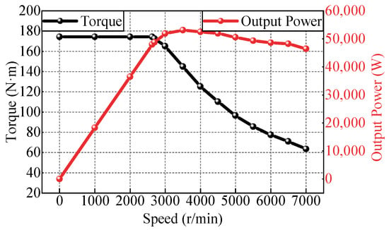
Figure 11.
Motor output characteristic curve.
In AFEEMs, the primary losses include stator copper loss, field copper loss, and core losses in both the stator and rotor. Copper losses are calculated based on winding resistance and RMS current, while core losses are obtained through finite element simulation. Motor efficiency is then derived accordingly. Key performance parameters are summarized in Table 7.

Table 7.
Rated operating condition parameters of the motor.
3.3. Comparison with Conventional Motors
To ensure consistency in core parameters such as motor volume and current density, a comparative analysis is performed between the proposed motor and a conventional radial flux EESM. The corresponding models are shown in Figure 12, with key dimensions and performance metrics listed in Table 8.

Figure 12.
Models of the two motors: (a) AFEESM model; (b) radial flux EESM model.

Table 8.
Comparison of parameters between the two motors.
The results indicate that both motors deliver comparable torque output. However, the proposed axial flux machine, leveraging a three-dimensional flux path, achieves higher material utilization within the same volume, resulting in a 15.14% increase in torque density over the radial flux counterpart. The efficiency maps in Figure 13 further highlight performance differences. While the axial flux motor exhibits a slightly lower peak efficiency (98.1%) than the radial flux motor, it provides a broader high-efficiency region under low-speed, low-torque conditions.

Figure 13.
Efficiency maps of the two motors: (a) AFEESM; (b) radial flux EESM.
Similarly, under identical dimensions, the proposed novel motor is compared with an axial flux PMSM, maintaining the same pole–slot combination and current density. The model is shown in Figure 14.

Figure 14.
Models of the two motors: (a) AFEESM model; (b) AFPMSM model.
Simulation results indicate that the permanent magnet machine, benefiting from inherent magnet excitation, achieves a higher peak torque. However, the efficiency map in Figure 15 highlights the advantages of the proposed motor: its peak efficiency is 0.6 percentage points higher. Moreover, in the high-speed region, the axial flux electrically excited machine maintains efficiency above 97%, whereas the permanent magnet machine drops to 93% due to its fixed excitation. These results demonstrate the superior high-speed performance of the proposed design.

Figure 15.
Efficiency maps of the two motors: (a) AFEESM; (b) AFPMSM.
Additionally, under identical dimensional constraints, the cost of the AFEESM is 40.56% lower than that of the PM counterpart, as shown in Table 9. This cost advantage primarily stems from the elimination of NdFeB magnets and the absence of specialized rotor structures such as magnetic bridges, resulting in reduced material and manufacturing costs.

Table 9.
Cost comparison of the two motors.
In summary, the proposed AFEESM retains the inherent advantages of axial flux topology, such as compact structure and high torque density. Additionally, it delivers higher efficiency at high speeds compared to axial flux permanent magnet machines, while significantly reducing overall cost.
3.4. Wireless Excitation Structure Expansion
To enhance system integration, a hollow shaft design is adopted, leveraging the ample radial space available in the AFEESM. This configuration enables the integration of a wireless excitation system within the shaft, eliminating the need for conventional brush mechanisms. The system schematic and a comparison with the traditional slip-ring structure are shown in Figure 16. A combination of T-shaped and canned magnetic cores is employed. The coil wound around the T-shaped magnetic core functions as the transmitting side and is fixed to the motor end cap, remaining stationary. The canned magnetic core serves as the receiving side, embedded in the inner wall of the hollow shaft and rotating with it. This configuration enables better compatibility and integration between the wireless excitation device and the motor structure without increasing the axial length.
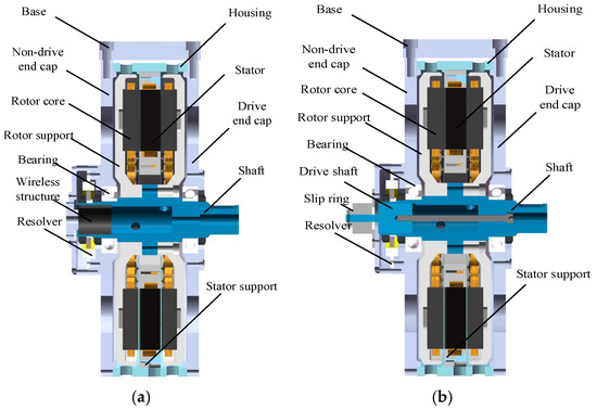
Figure 16.
Schematic diagram of the motor overall structure: (a) overall structure of the integrated wireless excitation module; (b) overall structure of the traditional slip-ring type.
4. Dual-Loop Composite Cooling Structure Design
The compact structure of axial flux machines poses significant thermal management challenges, further exacerbated by the presence of field windings in the rotor. To address this, a dual-channel hybrid cooling system is proposed, combining inner and outer loop water cooling for the stator slots with axial air cooling for the rotor. This configuration enables simultaneous and efficient heat dissipation from both stator and rotor components.
4.1. Inner and Outer Loop Water Cooling Design
A high-efficiency dual-loop water-cooling system is developed, as illustrated in Figure 17. The inner loop, inspired by slot cooling, brings the coolant into direct contact with the armature windings, enabling effective stator heat removal. The outer loop adopts a spiral water channel integrated into the housing, offering structural simplicity while covering both stator and rotor regions to enhance overall cooling performance. The stator support frame incorporates a clamping structure that hydraulically connects the inner and outer loops, forming a closed-loop circulation system. Additionally, the inner water channel is modularly embedded within the stator lamination stack, increasing the heat-exchange surface area and improving thermal efficiency.

Figure 17.
Integrated inner and outer water-cooling structure.
As the cooling water channels are integrated into the internal structure of the stator support frame and directly contact the stator windings, the stator region exhibits significantly lower temperatures compared to the rotor, as shown in Figure 18. The maximum stator winding temperature is 52.21 °C, while the rotor winding reaches a peak temperature of 165.63 °C.
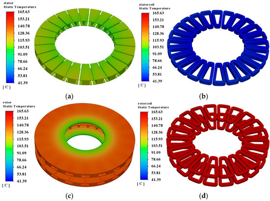
Figure 18.
Stator and rotor temperature distribution under water cooling: (a) stator core; (b) stator winding; (c) rotor core; (d) rotor winding.
4.2. Air Cooling Analysis
While the water cooling system effectively reduces stator temperature, rotor winding heat dissipation remains a challenge. Due to the complex thermal path and rotational constraints of the rotor, an air-cooling scheme is proposed to address rotor thermal management.
The proposed air-cooling structure incorporates an air inlet on the end cap and an outlet on the housing. Ventilation holes are integrated into the rotor to enhance internal airflow. A simplified schematic is shown in Figure 19.

Figure 19.
Simplified model of air-cooling motor.
As the air inlet is positioned on the end cover near the rotor, the rotor region exhibits lower temperatures than the stator under air cooling, as shown in Figure 20. At this point, the stator side experiences insufficient heat dissipation, reaching a peak temperature of 186.48 °C, while the rotor excitation winding peaks at 153.32 °C. These results indicate that the air-cooling structure is more effective for rotor-side thermal management.
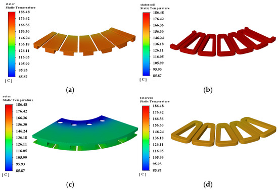
Figure 20.
Stator and rotor temperature distribution under air cooling: (a) stator core; (b) stator winding; (c) rotor core; (d) rotor winding.
In summary, the hybrid cooling structure, shown in Figure 21, integrates both air- and water-cooling systems. The dual-loop water-cooling system, featuring internal and external circulation, effectively dissipates heat from the stator. Simultaneously, the air-cooling system directly lowers the rotor winding temperature and enhances internal airflow, facilitating heat exchange between the rotor region and the housing-integrated water channels.
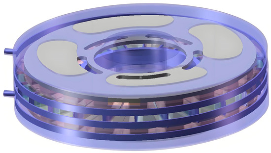
Figure 21.
Hybrid cooling motor model.
5. Experimental Verification
A prototype of the hollow-shaft wireless excitation axial flux electrically excited motor was fabricated based on the proposed design, as shown in Figure 22. The rotor shaft incorporates symmetrically distributed through-holes for routing the excitation winding and wireless power transmission coils. The rotor core was fabricated using a winding process, while the segmented stator core was assembled through lamination.
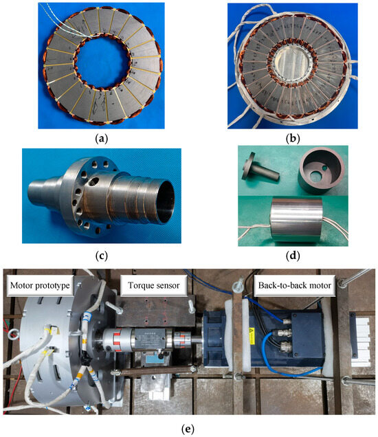
Figure 22.
Prototype of the novel axial flux electrically excited motor: (a) rotor core; (b) stator core; (c) shaft; (d) wireless excitation structure; (e) experimental test bench.
5.1. No-Load Test
An in-shaft wireless power supply device was used to supply the field winding for testing the motor’s no-load back EMF characteristics. Figure 23 shows the experimental waveforms of the wireless excitation system at field currents of 1 A and 4 A. Channel 1 shows the transmitter-side current (Ip); Channels 2 and 3 correspond to the receiver-side current (Is) and voltage (Us), respectively; and Channel 4 displays the output field current (If). The results confirm that excitation current can be linearly regulated by adjusting the front-stage voltage amplitude, meeting the dynamic requirements of the excitation system under varying operating conditions. Additionally, with excitation currents of 1 A, 2 A, 3 A, and 4 A, the rotor speed was linearly increased from 200 r/min to 1000 r/min. As shown in Figure 24, the measured back-EMF results closely match the simulation, particularly in the low-speed range. While slight deviations emerge at higher speeds, they remain within acceptable limits.

Figure 23.
Waveform of wireless excitation control: (a) if = 1 A; (b) if = 4 A.
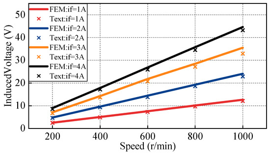
Figure 24.
No-load back EMF comparison.
5.2. Load Test
Load experiments ranging from 4 Nm to 16 Nm were conducted at rotational speeds of 1000 rpm and 2000 rpm. Parameters including motor input power, output power, and excitation loss were recorded using a power analyzer, with results summarized in Table 10. Under load conditions, the simulated efficiency generally exhibits a certain deviation from the measured values. This discrepancy arises partly from differences between the actual winding process of the axial flux motor and the simplified laminated structure used in the simulation model, which does not fully replicate the local eddy current paths and anisotropic magnetic permeability at the lamination interfaces. Furthermore, differences between the experimental control strategy and the simulation also contribute to this variance, indicating areas for future improvement and optimization.

Table 10.
Load operating condition test.
5.3. Dual-Loop Composite Cooling Temperature Verification
Due to current experimental constraints, motor thermal performance is primarily evaluated through simulation. The simulated temperature field of the hybrid-cooled motor is shown in Figure 25, with a maximum temperature of 119.18 °C. A detailed comparison of peak temperatures across key components under different cooling strategies is provided in Table 11. The results indicate that the hybrid cooling approach significantly reduces overall temperature and improves thermal uniformity. This confirms its effectiveness in enhancing heat dissipation and ensuring reliable motor operation.
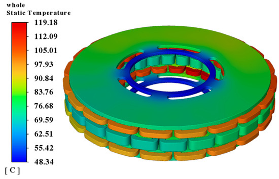
Figure 25.
Overall motor temperature distribution.

Table 11.
Comparison of component maximum temperature under different cooling conditions.
6. Conclusions
This paper proposes a high-torque-density composite-cooled axial flux electrically excited synchronous motor, employing a single-stator dual-rotor configuration. The selected 20-pole 24-slot combination achieves favorable torque and efficiency performance. Key structural parameters—including shaft-to-outer-diameter ratio and inner-to-outer-diameter ratio—are analyzed, showing that a smaller shaft ratio enhances torque density. The impact of tooth and yoke dimensions on the balanced distribution of stator and rotor losses is also investigated. Following multi-objective optimization, the torque density improves by 8.93%. Compared to a conventional radial flux electrically excited machine, the proposed design yields a 15.14% increase in torque density and achieves nearly 4% higher high-speed efficiency than an axial flux permanent magnet synchronous motor.
A composite cooling structure is proposed, comprising inner and outer loop water cooling and axial air cooling. The water cooling system integrates stator slot cooling and a helical full-coverage channel in the housing to efficiently dissipate heat from the stator windings. The air cooling path, formed by the end cap, housing, and rotor through-holes, directly lowers rotor winding temperature. With this hybrid approach, the maximum motor temperature is reduced to 119.18 °C, and the temperature rise across all components is significantly mitigated.
Finally, a prototype was developed and experimentally tested. The in-shaft wireless excitation system enabled wide-range controllability, and the motor exhibited favorable no-load excitation characteristics, providing preliminary validation of the design correctness of this novel axial flux wireless excitation motor. In the future, for applications requiring compact axial space and high torque density, such as hub direct-drive and flying cars, this type of motor demonstrates good adaptability and application potential due to its low cost and high reliability with no demagnetization.
Author Contributions
Conceptualization, S.C. and Y.Z.; methodology, Y.Z.; software, Y.Z. and C.F.; validation, Y.Z., K.X. and C.F.; formal analysis, B.S.; investigation, Y.Z.; resources, S.C.; data curation, K.X. and C.F.; writing—original draft preparation, Y.Z. and K.X.; writing—review and editing, S.C.; visualization, K.X.; supervision, B.S.; project administration, S.Q.; funding acquisition, S.C. All authors have read and agreed to the published version of the manuscript.
Funding
This work was supported by the National Natural Science Foundation of China under the grant 52177036.
Data Availability Statement
The original contributions presented in this study are included in the article. Further inquiries can be directed to the corresponding author(s).
Conflicts of Interest
The authors declare no conflict of interest.
References
- Benzaquen, J.; He, J.; Mirafzal, B. Toward More Electric Powertrains in Aircraft: Technical Challenges and Advancements. CES Trans. Electr. Mach. Syst. 2021, 5, 177–193. [Google Scholar] [CrossRef]
- Diao, C.; Zhao, W.; Wang, N.; Wang, X. Analysis of a High-Speed Axial Flux Permanent Magnet Synchronous Motor With Cost-Effective Hybrid Magnets. IEEE Trans. Mag. 2023, 59, 1–4. [Google Scholar] [CrossRef]
- Wang, Y.; Nuzzo, S.; Zhang, H.; Zhao, W.; Gerada, C.; Galea, M. Challenges and Opportunities for Wound Field Synchronous Generators in Future More Electric Aircraft. IEEE Trans. Transp. Electrif. 2020, 6, 1466–1477. [Google Scholar] [CrossRef]
- Nie, Y.; Brown, P.; Lodois, C. Low Switching Frequency Deadbeat-Direct Torque and Flux Control of Wound Field Synchronous Machines. In Proceedings of the 2018 IEEE Energy Conversion Congress and Exposition, Portland, OR, USA, 23–27 September 2018; pp. 6542–6549. [Google Scholar]
- Kandil, A. Investigation of the whirling motion and rub/impact occurrence in a 16-pole rotor active magnetic bearings system with constant stiffness. Nonlinear Dyn. 2020, 102, 2247–2265. [Google Scholar] [CrossRef]
- Leung, S.; Chan, C.C. A New Design Approach for Axial-Field Electrical Machines. IEEE Trans. Power Appar. Syst. 1980, PAS-99, 1679–1685. [Google Scholar] [CrossRef]
- Multi, A.; Garniwa, I. Design of Slotted Core Axial Flux Wound Rotor Synchronous Generator. In Proceedings of the 2013 International Conference on QiR, Yogyakarta, Indonesia, 25–28 June 2013; pp. 185–191. [Google Scholar]
- Endert, F.; Moeckel, A. Concept of a Two-Stator Axial Flux Machine with Field-Wound Fiber-Composite Rotor. In Proceedings of the Innovative Small Drives and Micro-Motor Systems, Würzburg, Germany, 10–11 September 2019; pp. 1–6. [Google Scholar]
- Schwarz, P.; Heidrich, T.; Möckel, A. Development of an Electrically Excited Axial Flux Machine with Stabilized Disk Rotor. In Proceedings of the 2023 IEEE International Electric Machines & Drives Conference, San Francisco, CA, USA, 15–18 May 2023; pp. 1–7. [Google Scholar]
- Yim, W.; Yoon, J.; Cha, J.; Bong, U.; Hahn, S. A Design Study on 20 kW Class Axial Flux Motor with HTS Field Winding for 100 MPa Liquid Hydrogen Pump. Cryogenics 2024, 139, 103829. [Google Scholar] [CrossRef]
- Fawzal, A.S.; Cirstea, R.M.; Gyftakis, K.N.; Woolmer, T.J.; Dickison, M.; Blundell, M. Fan Performance Analysis for Rotor Cooling of Axial Flux Permanent Magnet Machines. IEEE Trans. Ind. Appl. 2017, 53, 3295–3304. [Google Scholar] [CrossRef]
- Zaher, I.; Rodriguez, R.; Sayed, E.; Callegaro, A.; Goykhman, M.; Emadi, A. Effect of Rotor Geometry on Rotor Air Cooling of a Ventilated Axial-Flux Permanent Magnet Machine. In Proceedings of the 2021 IEEE Transportation Electrification Conference and Expo, Chicago, IL, USA, 21–25 June 2021; pp. 77–82. [Google Scholar]
- Jenkins, C.; Jones-Jackson, S.; Zaher, I.; Pietrini, G.; Rodriguez, R.; Cotton, J. Innovations in Axial Flux Permanent Magnet Motor Thermal Management for High Power Density Applications. IEEE Trans. Transp. Electrif. 2023, 9, 4380–4405. [Google Scholar] [CrossRef]
- Liu, W.; Dai, Y.; Zhao, J.; Wang, X. Thermal Analysis and Cooling Structure Design of Axial Flux Permanent Magnet Synchronous Motor for Electrical Vehicle. In Proceedings of the 22nd International Conference on Electrical Machines and Systems, Harbin, China, 11–14 August 2019; pp. 1–6. [Google Scholar]
- Chang, J.; Fan, Y.; Wu, J.; Zhu, B. A Yokeless and Segmented Armature Axial Flux Machine with Novel Cooling System for In-Wheel Traction Applications. IEEE Trans. Ind. Electron. 2021, 68, 4131–4140. [Google Scholar] [CrossRef]
- Liu, C.; Gerada, D.; Xu, Z.; Chong, Y.C.; Michon, M.; Goss, J. Estimation of Oil Spray Cooling Heat Transfer Coefficients on Hairpin Windings with Reduced-Parameter Models. IEEE Trans. Transp. Electrif. 2021, 7, 793–803. [Google Scholar] [CrossRef]
- Zhang, F.; Gerada, D.; Xu, Z.; Liu, C.; Zhang, H.; Zou, T. A Thermal Modeling Approach and Experimental Validation for an Oil Spray-Cooled Hairpin Winding Machine. IEEE Trans. Transp. Electrif. 2021, 7, 2914–2926. [Google Scholar] [CrossRef]
- Shen, Q.; Liu, L.; Zhu, H.; Zhang, T.; Li, J.; Tian, J. Design and Simulation Analysis of Oil Cooling System for Axial Flux Permanent Magnet Motors. In Proceedings of the 2023 26th International Conference on Electrical Machines and Systems (ICEMS), Zhuhai, China, 5–8 November 2023; pp. 5079–5084. [Google Scholar]
- Zhu, G.; Li, L.; Mei, Y.; Liu, T.; Xue, M. Design and Analysis of a Self-Circulated Oil Cooling System Enclosed in Hollow Shafts for Axial-Flux PMSMs. IEEE Trans. Veh. Technol. 2022, 71, 4879–4888. [Google Scholar] [CrossRef]
Disclaimer/Publisher’s Note: The statements, opinions and data contained in all publications are solely those of the individual author(s) and contributor(s) and not of MDPI and/or the editor(s). MDPI and/or the editor(s) disclaim responsibility for any injury to people or property resulting from any ideas, methods, instructions or products referred to in the content. |
© 2025 by the authors. Licensee MDPI, Basel, Switzerland. This article is an open access article distributed under the terms and conditions of the Creative Commons Attribution (CC BY) license (https://creativecommons.org/licenses/by/4.0/).