Article

A New Model to Investigate Effect of Heat Conduction Between Tubes on Overall Performance of a Coil Absorber for Flat-Plate Solar Collectors

by
Elena G. Martínez-Morales
1,
Ricardo Romero-Méndez
2,*,
Francisco G. Pérez-Gutiérrez
2 and
Pedro García-Zugasti
3
1
Instituto de Energías Renovables, Universidad Nacional Autónoma de México, Temixco 62580, Mexico
2
Facultad de Ingeniería, Universidad Autónoma de San Luis Potosí, San Luis Potosí 78290, Mexico
3
Departamento de Metal Mecánica, Instituto Tecnológico de San Luis Potosí, Tecnológico Nacional de México, San Luis Potosí 78436, Mexico
*
Author to whom correspondence should be addressed.
Energies 2025, 18(16), 4360; https://doi.org/10.3390/en18164360
Submission received: 19 July 2025 / Revised: 8 August 2025 / Accepted: 9 August 2025 / Published: 15 August 2025
(This article belongs to the Section A2: Solar Energy and Photovoltaic Systems)

Abstract

Solar heaters are a sustainable solution to lower operating heating costs for diverse applications. Improving the design of these devices promotes the adoption of this technology to reduce the environmental impact of traditional gas water heaters. The present paper studies heat transfer along the plate-fins of serpentine-type flat-plate solar collectors. The focus of this investigation is the analysis of tube-to-tube thermal conduction through the absorbent plate and its effect on the heat gain of the circulating fluid. The model used here does not consider the adiabatic boundary condition in the plate mid-distance between tubes but applies the prescribed temperatures of the tubes as a boundary condition for the plate-fins. This type of boundary condition allows for heat conduction between rows of tubes. The analysis demonstrates that tube-to-tube heat conduction along the absorber plate has a detrimental effect on the heat gain of the circulating fluid. This effect is responsible for a decrease of up to 10% of the circulating fluid heat gain. This investigation defines the set of parameters that affect the performance of plate solar heaters because of tube-to-tube thermal conduction along the plates, and it helps to choose operation and designs parameters, leading to better design of these devices.

1. Introduction

Solar collectors are devices used as a means of collecting solar energy to heat a circulating fluid [1,2]. A common design for a solar collector is the tube-on-plate solar collector. It uses an absorber copper plate located on top of a grid of pipes arranged in a serpentine loop covered by an insulated substrate. This design incorporates a translucent acrylic or glass plate separated by an air gap from the copper plate to reduce heat loss. The copper plate transfers heat from solar irradiation to fluid circulating through tubes, which behave as an extended surface. Among the critical parameters affecting the performance of solar collectors are the absorber plate-fins, pipe diameter, length, pitch, and circuitry design.
Recent investigations have focused on different aspects of flat-plate solar water heaters [3,4,5,6,7,8,9,10,11,12,13]. These can be modeled using the thermal resistances between the fluid in the tubes and the surrounding environment. The absorber plate and tubes are considered as fins. The efficiency and thermal resistance of the fins are calculated by [14,15,16]. Duffie and Beckman [14] assumed zero heat flow in the cross-section of the plate at the centerline between adjacent tubes as one of the boundary conditions necessary to solve the fin second-order differential equation. This assumption facilitates analysis, because it uncouples the tube-to-tube dependence of the fluid temperature distribution in the inflow direction.
In serpentine-type flat-plate solar collectors, the fluid moves inside straight sections of adjacent pipes connected at their ends by U-pipes. This allows a single stream to flow in a back-and-forth trajectory. As the fluid heats up while it flows, the hotter temperature is found towards the exit of the solar collector. This temperature difference produces a non-adiabatic condition in the cross-section of the plate at the centerline between the adjacent tubes. This condition makes the temperature distribution along the pipes different from that obtained by the model proposed by [14]. It is not clear how important it may be to use a different type of boundary condition for the centerline of the plate absorber fins. We believe that it is relevant to analyze this situation, build a modified mathematical model that includes tube-to-tube conduction along the absorber plates, and use it to determine the set of parameters that affect the fluid outlet temperature.
The existence of longitudinal fin conduction has been recognized by several authors as a possibility for a variety of heat exchanger configurations [17,18,19,20,21]. Romero-Méndez [22] considered a model that includes tube-to-tube heat conduction for plate-fin and tube heat exchangers. Singh et al. [23,24] analyzed how tube-to-tube fin conduction affects heat exchangers operating at large temperature differences. They found that fin conduction between neighboring tubes degrades heat exchanger performance and proposed the use of cut fins to avoid this effect.
Recent numerical modeling and optimization algorithms for cooling heat exchangers have considered tube-to-tube conduction. Ding et al. [25] built a computer code to predict the performance of complex plate-fin and tube heat exchanger circuits that incorporate interactions between different rows of tubes. Sarfraz et al. [26] state that (i) serpentine heat exchanger performance is influenced by tube-to-tube conduction; (ii) coil models that exclude cross-fin conduction are biased and under-predict the capacity of the heat exchanger; and (iii) cross-fin conduction is important in coils with increased difference in air and water temperatures at the coil inlet. The authors proposed the use of a plate-fin and tube heat exchanger model that incorporates tube-to-tube fin conduction between adjacent tubes. They compared the results of their numerical model with experiments on a test bench and found that neglecting tube-to-tube conduction through the fins causes significant discrepancies in predicted coil performance.
Sarfraz et al. [27] developed a novel segment-by-segment model of a fin-tube heat exchanger that eliminates the need to calculate the heat transfer between adjacent tube segments through the fins. This reassignment of the fin area decreases the simulation time and computational costs. However, it still accounts for cross-fin conduction in the analysis in a simplified manner. Sarfraz et al. [28] present a validation of two different heat exchanger models that consider cross-fin conduction against two-phase refrigerant data. Saleem et al. [29] explore how refrigerant circuitry can influence cross-fin conduction in multi-circuit evaporator coils and conclude that cross-fin conduction needs to be considered in heat exchanger modeling to accurately predict heat exchanger performance. Garcia et al. [30] utilize graph theory concepts to model tube–tube adjacency in finned-tube heat exchangers. Macchitella et al. [31] present a review in which they collected, analyzed, and summarized design optimization methods with a focus on circuitry configuration for plate-finned tube heat exchangers used for refrigeration.
Based on the literature review, and to the best of our knowledge, there is no categorical evidence for whether tube-to-tube conduction in serpentine-array solar panels is as important as in plate-fin and tube heat exchangers. There is no other analytical model that includes tube-to-tube conduction along the absorber plates of solar collectors. The investigation developed here is important because it provides a comparison of models that do and do not include tube-to-tube conduction along the absorber plate. The investigation also gives insight into the values of the geometrical and operational parameters under which tube-to-tube conduction is significant.

2. Collector Model and Formulation

Figure 1 shows the geometry of a flat-plate solar collector of a serpentine array. It consists of an optically absorbing flat plate made of a highly conductive metal coupled to a serpentine pipe array buried in insulation. The plate transfers heat from solar irradiation to the serpentine pipe arrangement by conduction acting as a fin. The circulating fluid is heated as it flows downstream of the pipes, leaving the device at a higher temperature than at the entrance.
Assuming that the solar collector has N straight sections of pipe, each of length L, and numbering the pipe section from left to right, there is a connection between two consecutive pipes through the U-turns. The global coordinate z indicates the position of the pipe measured from the inlet plane. The fluid temperature will increase or decrease in the direction of coordinate z, depending on whether the tube row is odd or even. The model developed here assumes steady-state conditions and uniform fluid, pipe, and plate properties, and that all solar irradiation that is not returned to the environment is absorbed by the in-tube fluid. The heat balance of a differential section of the pipe for the row jth is
( 1 ) j m ˙ C d T = ( T j T j w ) d z R T
The coefficient ( 1 ) j takes into account the fact that the flow in the tube is in the positive z direction for the odd rows of tubes and in the negative z direction for the even rows of tubes; m ˙ and C are the mass flow rate and the specific heat of the fluid in the tube, respectively; T j w and T j are the contact strips of the tube–plate and the fluid temperatures, respectively. R T is the resistance to heat transfer per unit length between the contact point of the tube–plate and the fluid in the tube, expressed by two parallel tracks to transfer heat as
R T = g h i + η d h i ( π D i g ) 1
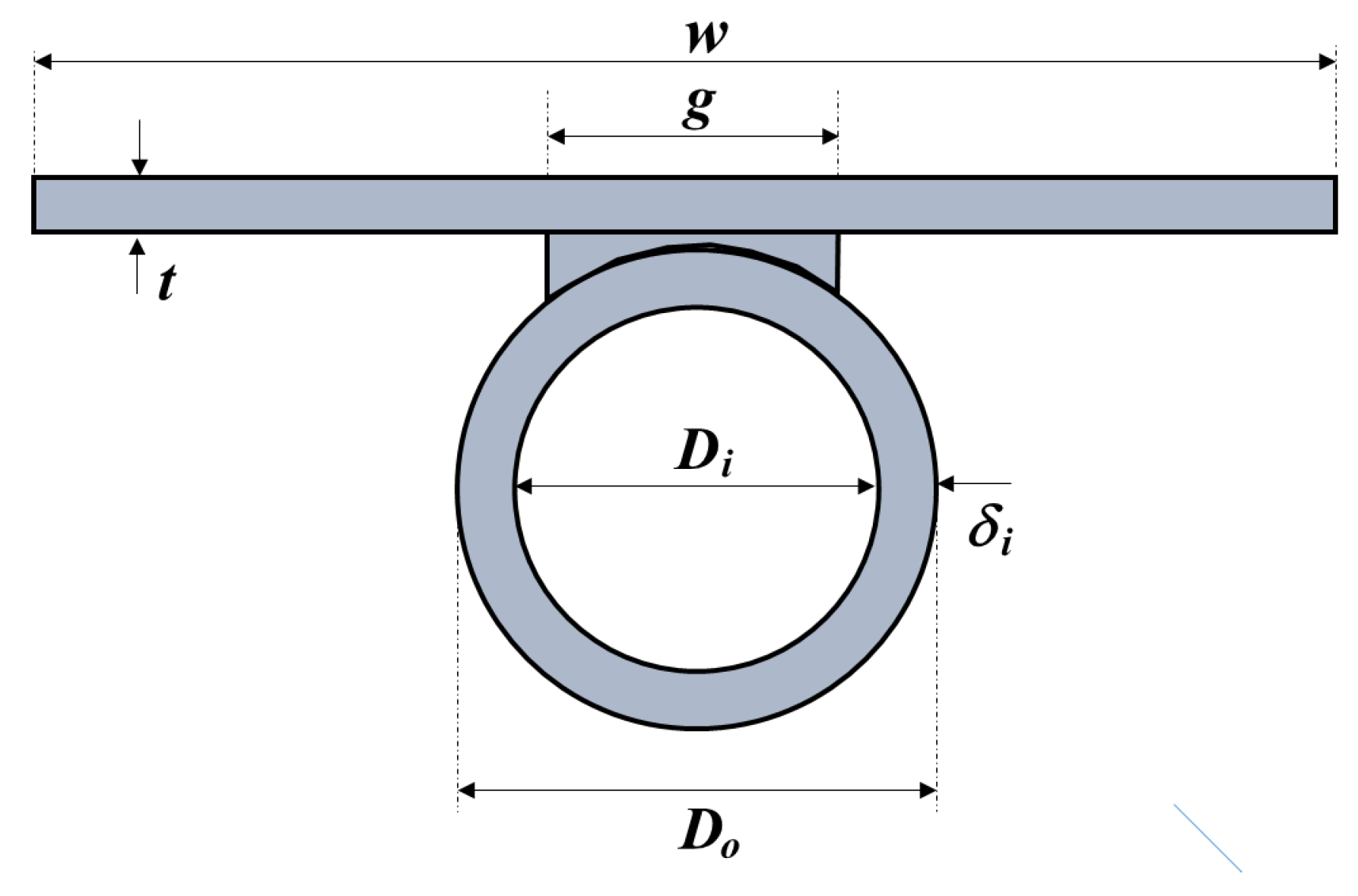
where h i is the convective heat transfer coefficient between the inner tube surface and the fluid in the tubes, D i is the inner diameter of the tube, g is the length of the strip where the tube and plate are soldered, and η d is the efficiency of the fin, considering each half of the tube as an adiabatic tip fin of length ( π D i g ) / 2 and thickness δ i = ( D o D i ) / 2 . The dimensions and details of a flat plate solar collector are in Figure 2.
Calculating R T requires the determination of h i and η d . The coefficient of convective heat transfer between the inner tube surface and the fluid in the tube is obtained using standard pipe flow laminar and turbulent heat transfer correlations [32,33]:
N u D i = 3.56 if R e D i < 2300
N u D i = ( f / 8 ) ( R e D i 1000 ) P r 1 + 12.7 ( f / 8 ) 1 / 2 ( P r 2 / 3 1 ) if R e D i > 3000
where f is the friction factor of the smooth pipe:
f = ( 0.79 ln ( R e D i ) 1.64 ) 2
In these calculations, R e D i = V D i / ν is the Reynolds number, P r is the fluid Prandtl number, and N u D i = h i D i / k f is the Nusselt number. V is the mean velocity of the fluid within the pipe. For 2300 < R e D i < 3000 , N u D i is interpolated using their values in R e D i = 2300 and R e D i = 3000 .
The efficiency of the pipe-fin is that of an adiabatic tip fin considering each half of the pipe:
η d = tanh [ m ( π D i g ) / 2 ] m ( π D i g ) / 2
where
m = h i k δ i
Figure 3 illustrates the heat transfer interactions of the extended surfaces. On top of the pipes, there is an absorber plate, on which solar irradiation is incident. The plate is at a temperature higher than that of the surroundings, such that part of the solar energy returns to the ambient by convection. The rest of the heat flows by conduction along the plates, acting as fins, towards the plate–tube connecting strips.
The heat absorbed by the in-tube fluid comes from the net solar absorption of the plates. Some of this energy passes directly from a strip connecting the plate and the tube surface, while the other part comes from the extended surfaces:
q j = q c o n t q t u b
where q j is the rate of heat transfer from the absorber plate to the in-tube fluid;
q j = ( T j w T j ) d z R T
where q c o n t is the heat absorbed by the tube directly from the plate strip that adheres to the tube;
q c o n t = g [ S S U L ( T j w T ) ] d z
where S S is the net solar irradiation absorbed by the plate per unit length in the direction of the tube length, g is the length of the strip that attaches the tube and the plate, and U L is the overall heat transfer coefficient between the absorber plate and the ambient air at T .
From Equation (8), q t u b is the heat transferred between the tubes along the plate; the minus sign comes from the convention that the heat leaves tube j in the direction of tubes j 1 and j + 1 :
q t u b = q j + q j +
To calculate q j and q j + , the plates must be analyzed as extended surfaces that connect to the plate–tube junction. The heat balance of a plate differential section of length d x can be expressed as
d 2 T p d x 2 U L k t ( T p T ) = S S k t
Here, T p is the plate temperature, t is the thickness of the collector plate, and k is the thermal conductivity of the tubes and plate.
This equation is applied for the domain that goes from the plate–tube joint, j, to the adjacent plate–tube joint, j + 1 , 0 x ( w g ) . The boundary conditions for this case are the following:
T p ( 0 ) = T j w
T p ( w g ) = T j + 1 w
T j w and T j + 1 w are the temperatures at the plate–tube contact zone of the tubes j and j + 1 , respectively.
By solving Equation (12) together with boundary conditions (13) and (14), it is possible to obtain the heat flow that leaves the plate–tube juncture j in the direction of the plate–tube juncture j + 1 :
q j + = k t d z [ d T p d x ] 0 = m k t d z ( T j w T S S U L ) cosh ( m ( w g ) ) ( T j + 1 w T S S U L ) sinh ( m ( w g ) )
where
m = U L k t
Similarly, Equation (12) is applied to the domain that goes from the plate–tube joint, j, to the adjacent plate–tube joint, j 1 , 0 x ( w g ) . The boundary conditions for this case are the following:
T p ( 0 ) = T j w
T p ( w g ) = T j 1 w
where T j w and T j 1 w are the temperatures in the contact zone of the plate–tube of tubes j and j + 1 , respectively,
q j = k t d z [ d T p d x ] 0 = m k t d z ( T j w T S S U L ) cosh ( m ( w g ) ) ( T j 1 w T S S U L ) sinh ( m ( w g ) )
Equation (15) applies to tube rows 1 j N 1 , while Equation (19) is useful for tube rows 2 j N . Both ends of the solar collector—that is, tube rows 1 and N—are special cases, where the tubes do not have both neighboring tubes. In those cases, the plate on one side is modeled as a fin with an adiabatic fin tip. In those two cases,
q 1 = k t d z [ d T p d x ] 0 = m k t d z ( T 1 w T S S U L ) tanh ( m ( w g 2 ) )
q N + = k t d z [ d T p d x ] 0 = m k t d z ( T N w T S S U L ) tanh ( m ( w g 2 ) )
Equation (1) expresses the heat transferred to the fluid by the tube wall and is applied to each row. The only position where the fluid temperature is known beforehand is the solar collector inlet, that is, the fluid temperature of the first tube in position z = 0 :
T 1 ( 0 ) = T i n
The in-tube fluid also presents conditions that link the temperatures of adjacent pipes at the U-turns. Here, the U-turns are assumed to be adiabatic sections of the solar collector, and the prescribed condition is that the temperature at which the fluid leaves one tube is equal to the temperature with which it enters the connecting pipe, expressed mathematically as
T j ( L ) = T j + 1 ( L ) if   j   is   odd
T j ( 0 ) = T j + 1 ( 0 ) if   j   is   even

2.1. Non-Dimensionalization

The dimensionless variables used for scaling purposes are
ξ = x L
θ j = T j w T S S U L T i n T S S U L
ψ j = T j T S S U L T i n T S S U L
Here, L is the length of each straight section of the pipe.
The dimensionless version of Equation (1) is
d ψ j d ξ = σ ( 1 ) j ( ψ j θ j )
The dimensionless form of the set of Equation (8) is
ψ 1 = [ α + γ β ( coth β + tanh β 2 ) + 1 ] θ 1 [ γ β sinh β ] θ 2
ψ j = [ γ β sinh β ] θ j 1 + [ α + 2 γ β coth β + 1 ] θ j [ γ β sinh β ] θ j + 1 for 2 j N 1
ψ N = [ γ β sinh β ] θ N 1 + [ α + γ β ( coth β + tanh β 2 ) + 1 ] θ N
where
σ = L R T m ˙ C
α = g U L R T
β = m ( w g )
γ = k t w g R T
The boundary conditions of the problem are the following:
ψ 1 ( 0 ) = 1
ψ j ( 1 ) = ψ j + 1 ( 1 ) i f j is   odd
ψ j ( 0 ) = ψ j + 1 ( 0 ) i f   j   is   even
By following this non-dimensionalization of the equations, the resulting equations and the procedure to solve them are similar to those of [22]. The equations in vectorial form are as follows.

2.2. Vectorial Expression of Equations

The dependent variables written as vectors are
Ψ ( ξ ) = ψ 1 ( ξ ) ψ 2 ( ξ ) ψ N 1 ( ξ ) ψ N ( ξ )
and
Θ ( ξ ) = θ 1 ( ξ ) θ 2 ( ξ ) θ N 1 ( ξ ) θ N ( ξ )
Introducing these forms, Equations (28)–(31) become
d Ψ d ξ = σ S ( Ψ Θ )
Ψ = A Θ
where
S = [ ( 1 ) i δ i j ]
and
A = ν ϵ 0 0 0 0 ϵ ν ϵ 0 0 0 0 ϵ ν ϵ 0 0 0 0 0 0 ϵ ν ϵ 0 0 0 0 ϵ ν ϵ 0 0 0 0 ϵ ν
where
ν = α + γ β ( coth β + tanh β 2 ) + 1
ν = α + 2 γ β coth β + 1
ϵ = γ β sinh β
We introduce Equation (42) into Equation (41):
d Ψ d ξ = σ S ( I A 1 ) Ψ
The solution of the differential equation system is as follows:
Ψ ( ξ ) = e [ σ S ( I A 1 ) ξ ] Ψ ( 0 )
All elements of the vector Ψ ( 0 ) are unknown, with the exception of Ψ 1 ( 0 ) = 1 . By first evaluating in x = 1 , the following result is obtained:
Ψ ( 1 ) = e [ σ S ( I A 1 ) ] Ψ ( 0 )
Since the set of resulting equations is similar, the steps described in [22] to solve the cases of even or odd numbers of tubes also apply here.
Once Ψ ( 0 ) is obtained, the temperature anywhere in the tube can be obtained from Equation (49). The dimensionless fluid temperature goes from 1 at the inlet to potentially 0 at the exit (if the solar heater has a sufficiently large area). The fluid absorbs more heat if the outlet value of Ψ N is closer to zero. The expression 1 Ψ N , o u t is a measure of the amount of heat absorbed by the fluid in the solar collector.
The total heat absorbed by the in-tube fluid can be determined by
Q = m ˙ C ( T o u t T i n ) = m ˙ C ( T i n T S S U L ) ( 1 ψ N , o u t )
In order to determine the effect of tube-to-tube conduction along the flat plates, a parameter that indicates the decrease in fluid heat gain due to the tube-to-tube conduction is defined as the ratio of heat transfer obtained when modeling the solar heater as described above to the heat transfer obtained using the traditional model of applying adiabatic fin tip conditions in the mid-distance between adjacent tubes:
R = Q Q ^
The lower R is, the more significant the tube-to-tube conduction.
Q ^ is the heat transfer obtained in the solar collector if the adiabatic fin tip conditions are used between adjacent tubes, in which case the matrix A of Equation (44) becomes diagonal, with elements:
ν = α + 2 γ β tanh β 2 + 1
And, by Equation (49) the temperature of the in-tube fluid outlet becomes
ψ ^ N , o u t = e [ σ ( 1 1 ν ) N ]
Equation (52) becomes
R = 1 ψ N , o u t 1 ψ ^ N , o u t

3. Results and Discussion

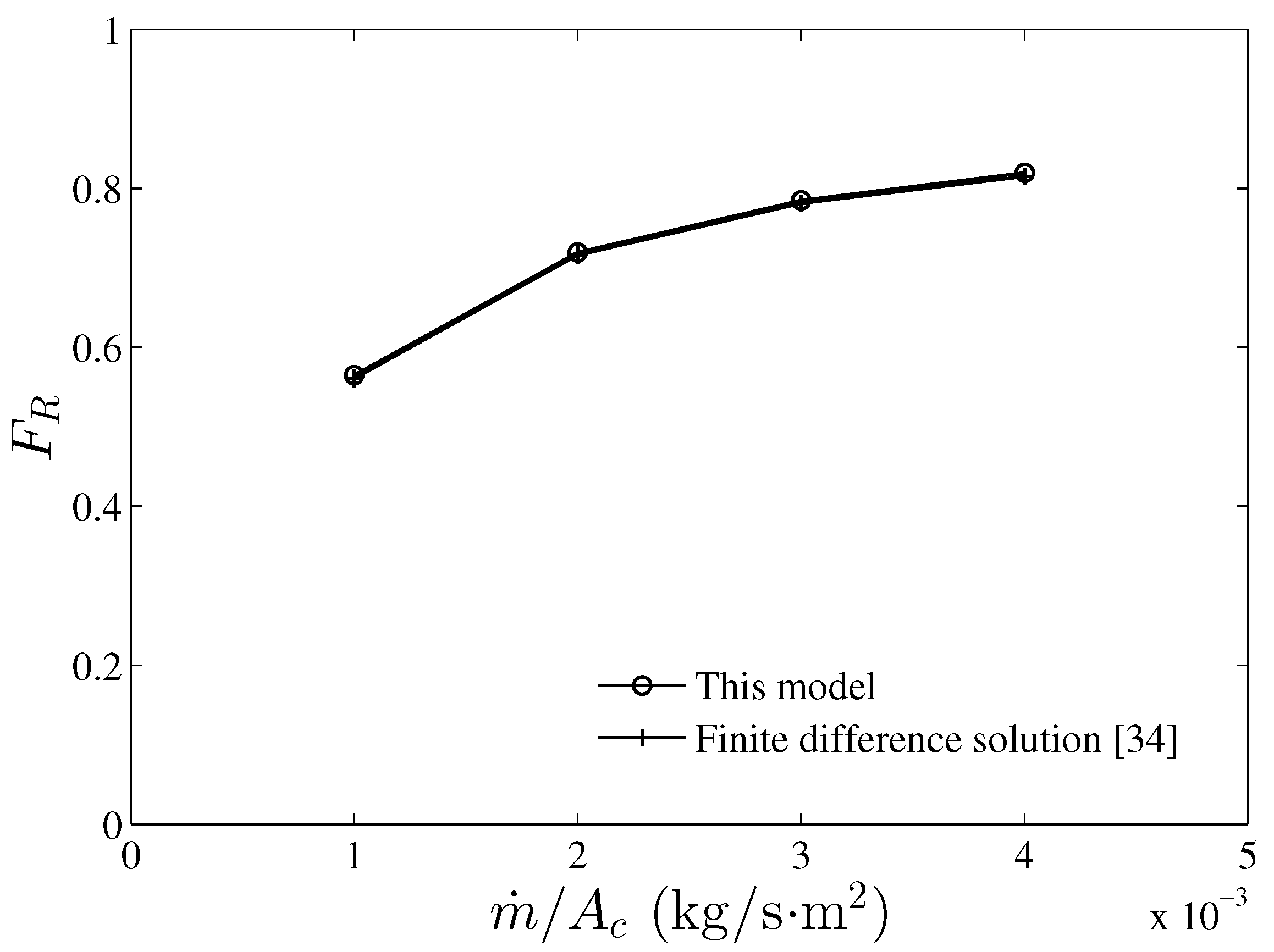
The mathematical model developed was validated by comparing the performance results obtained with a finite-difference solution for a flat-plate serpentine collector presented by [34]. The comparison is with Figure 3.10 of [34], where the author presents a graph of the collector heat removal factor F R vs. m ˙ / A c , A c = w N L is the collector area, and F R is defined as
F R = m ˙ C ( T o u t T i n ) S S U L ( T i n T )
Figure 4 presents the comparison of the results of [34] and those resulting from the methodology introduced in our research. The good agreement of both results is observable.
To assess the relevance of tube-to-tube conduction in coiled flat-plate solar collectors, a set of typical geometric and operational conditions for this type of device is specified. Table 1 presents typical values of commercial flat-plate solar collectors used as a standard in this investigation.
For the set of parameters and properties detailed in Table 1, an estimation of the effect of tube-to-tube conduction along the plate on the performance of this flat-plate solar collector gives R = 0.9442 . This indicates that for these solar collector conditions, tube-to-tube conduction is responsible for reducing 5.58% of the total heat transfer of the device, for which reason it is relevant to include tube-to-tube conduction in the analysis of the coiled flat-plate solar collector.
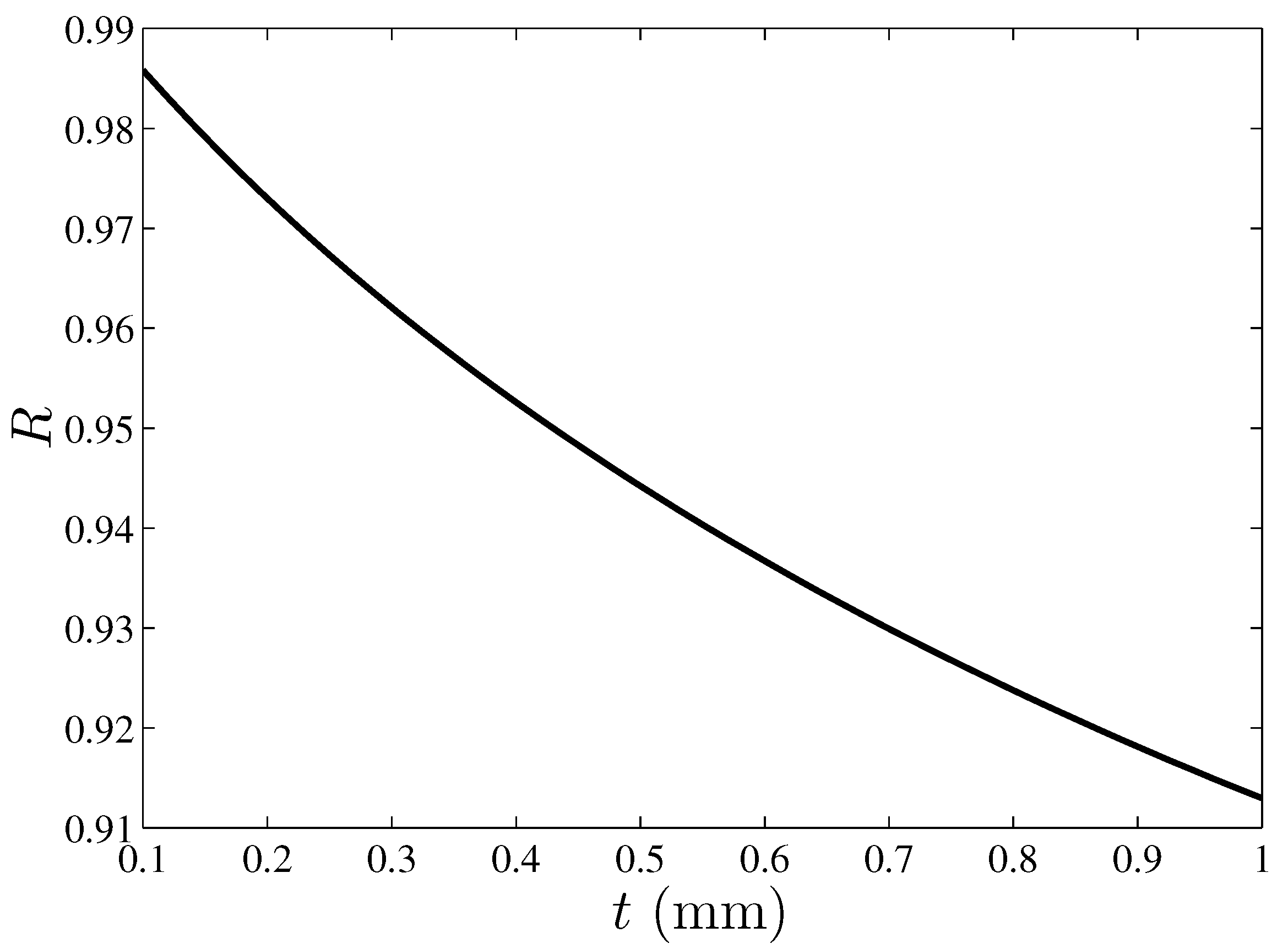
To learn more about the relevance of tube-to-tube heat conduction along the plates of flat-plate solar collectors, an analysis of the influence of different parameters was performed. The most influential parameter seems to be the thickness of the plate. Figure 5 shows how parameter R varies with the thickness of the plate. As seen in the figure, tube-to-tube conduction increases monotonically its importance when the plate thickness is increased; this happens because the cross-sectional area across which the heat flows between the tubes is directly proportional to the thickness of the plate. As manufacture permits the use of thinner plates, tube-to-tube conduction decreases its relevance.
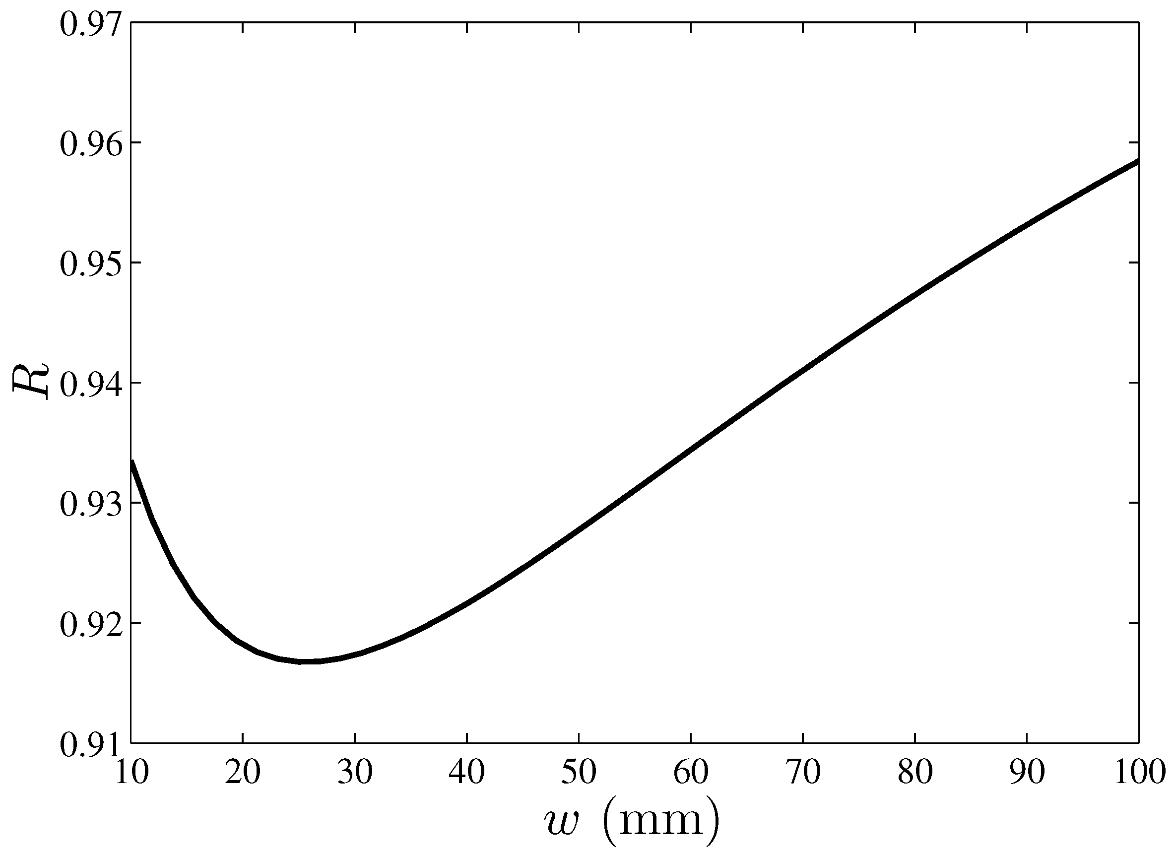
Figure 6 shows the variation of R with the distance between adjacent tubes. For small w, tube-to-tube conduction increases as the tubes separate from each other. The parameter R indicates the maximum conduction between adjacent tubes at some point after which the conduction from tube to tube decreases. For tubes very close to each other, the surface area of the plate is small, and, therefore, a limited amount of heat is transferred to the fluid inside the tubes per row. Hence, the temperature difference of the fluid between adjacent tubes is small, reducing tube-to-tube heat conduction (small temperature gradient between adjacent tubes). When the separation between adjacent tubes increases, the surface area of the plate is large and more heat is absorbed by the plate and is transferred to the fluid, increasing the temperature difference between adjacent tubes. In contrast, the longer distance between adjacent tubes increases the thermal resistance of the plate to conduction between adjacent tubes. At some w ( w 25 mm for the case of Figure 6) there is a maximum conduction between the tubes, after which the growth of thermal resistance between adjacent tubes dominates, so the conduction between the tubes loses importance as w grows.
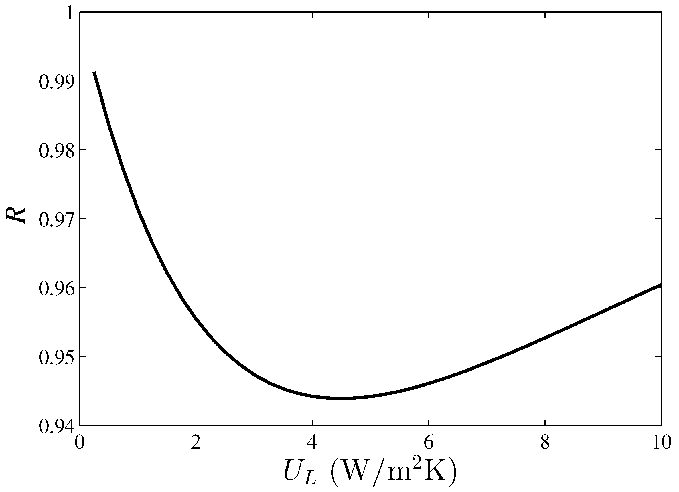
Figure 7 shows the decrease in fluid heat gain due to the tube-to-tube conduction effect as a function of the overall heat transfer coefficient of the absorber plate, R vs. U L . A value U L = 0 means that none of the solar irradiation heat absorbed by the plate is returned to the environment and surroundings. In that case, the plate temperature increases, making the plate temperature distribution between tubes more symmetric, reducing tube-to-tube conduction. A very large value of U L means that a large part of the heat absorbed by solar irradiation on the plate returns to the surroundings, which implies lower absorption of heat by the in-tube fluid and a smaller temperature gradient between adjacent tubes, also reducing tube-to-tube conduction along the plates.
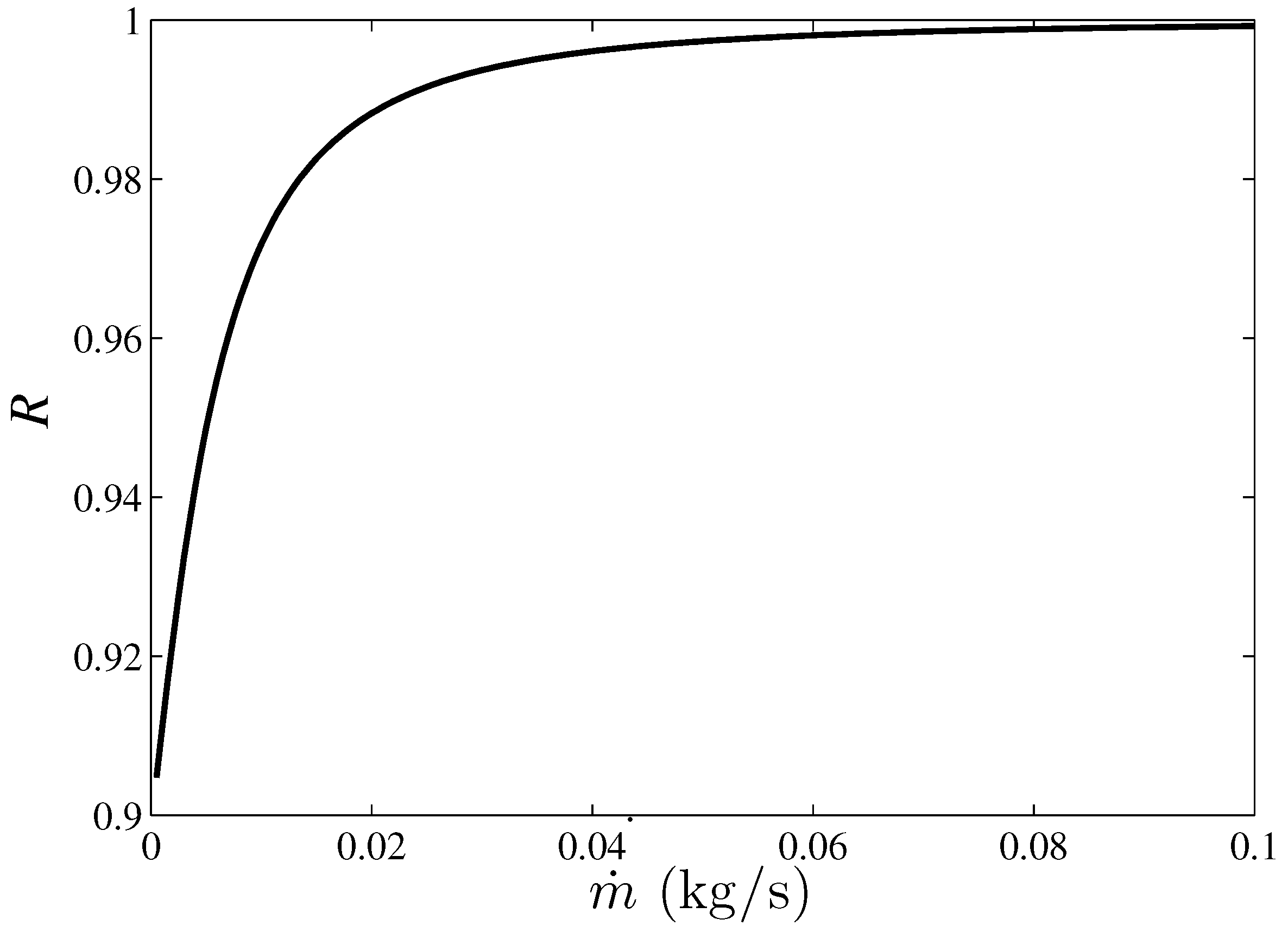
Figure 8 presents the decrease in the fluid heat gain due to tube-to-tube conduction as a function of the mass flow rate of the fluid in the tube, R v s . m ˙ . If the mass flow rate is too large, the in-tube fluid experiences only a small temperature gradient as it flows along the solar collector. In such a case, the temperature gradient between adjacent tubes is negligible, as is the tube-to-tube conduction along the plates. When the in-tube fluid mass flow rate is small, a large temperature gradient between adjacent tubes occurs, favoring tube-to-tube conduction along the plates.
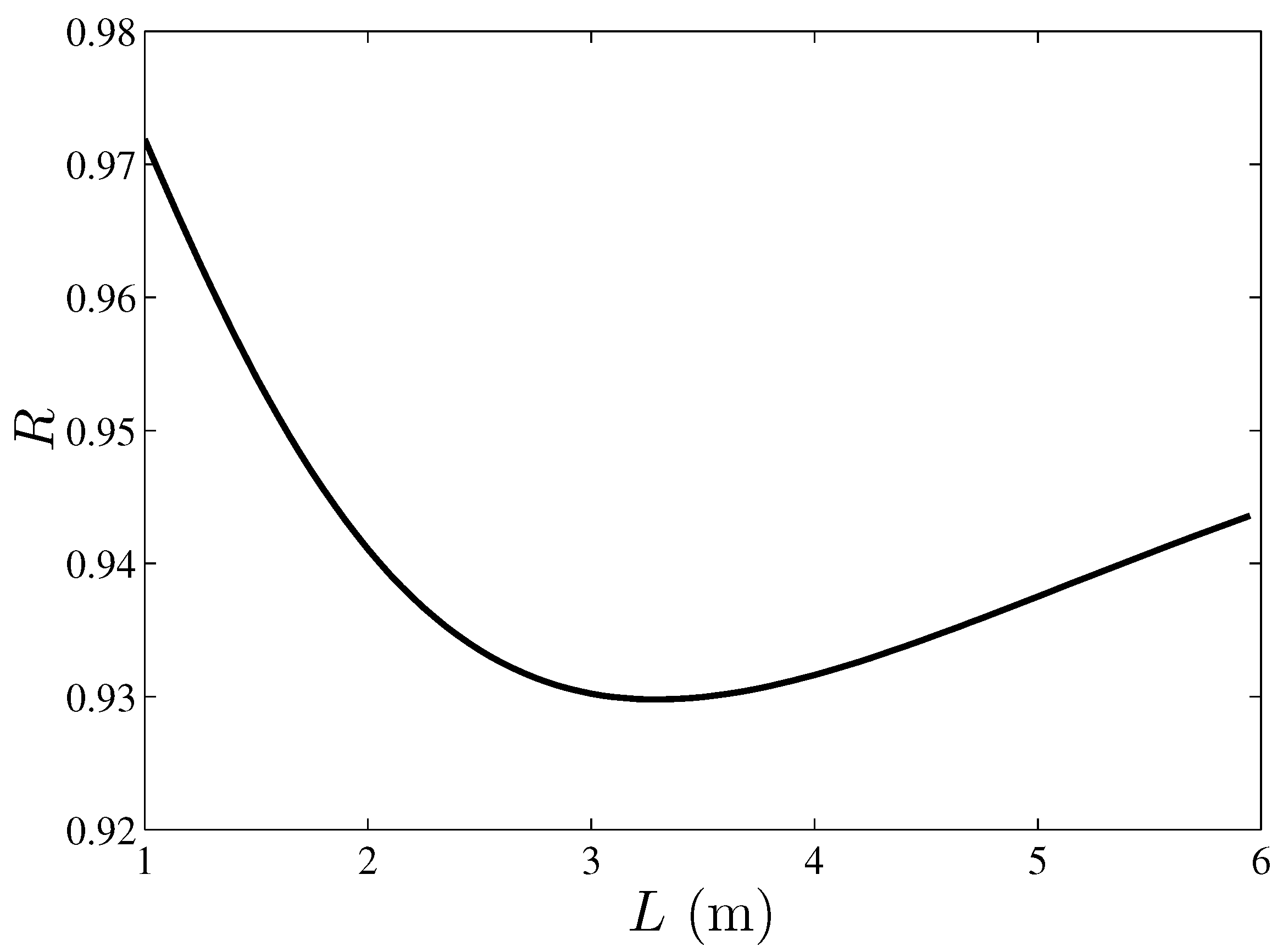
Figure 9 shows the decrease in fluid heat gain due to tube-to-tube conduction as a function of tube length, R v s . L . For short straight sections of pipe, tube-to-tube conduction decreases because there is not a large temperature difference between adjacent tubes at the same position z, because the heat transfer area of each row decreases linearly with tube length. For very long stretches of pipe with all other parameters fixed, the total heat transfer area increases linearly with the length of the tube, and the in-tube fluid approaches a limit temperature, independently of whether or not tube-to-tube conduction occurs, so R tends to a limit for large L.
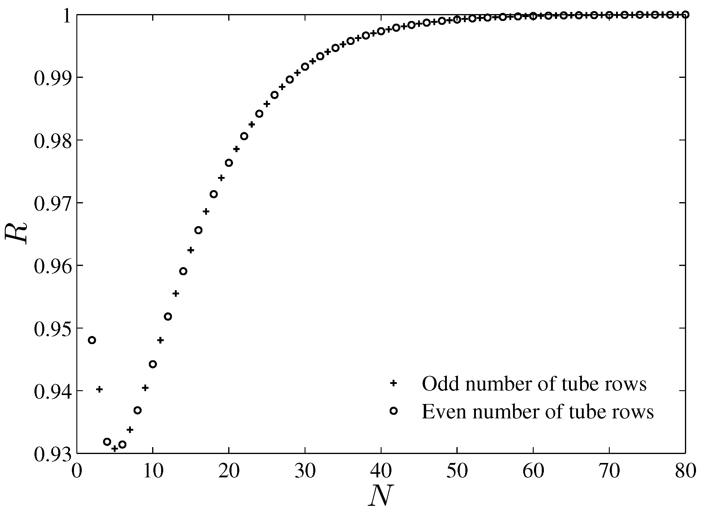
Figure 10 presents the decrease in fluid heat gain due to tube-to-tube conduction as a function of the number of rows of tubes, R v s . N , for the case of even and odd numbers of rows of tubes. When N is large, the heat exchanger is also large and the in-tube fluid approaches a limit temperature, independently of whether tube-to-tube conduction occurs, so that R tends to one for large N. When N is small, the plate section between tubes is lower, which also influences the heat transfer on the end side of the plates (first and last rows of the solar collector), so that an important part of the heat transfer is not between tubes and the importance of tube-to-tube conduction decreases. The limiting case is when N = 1 , where there is a single tube, so there is no tube-to-tube heat conduction and R = 1 .
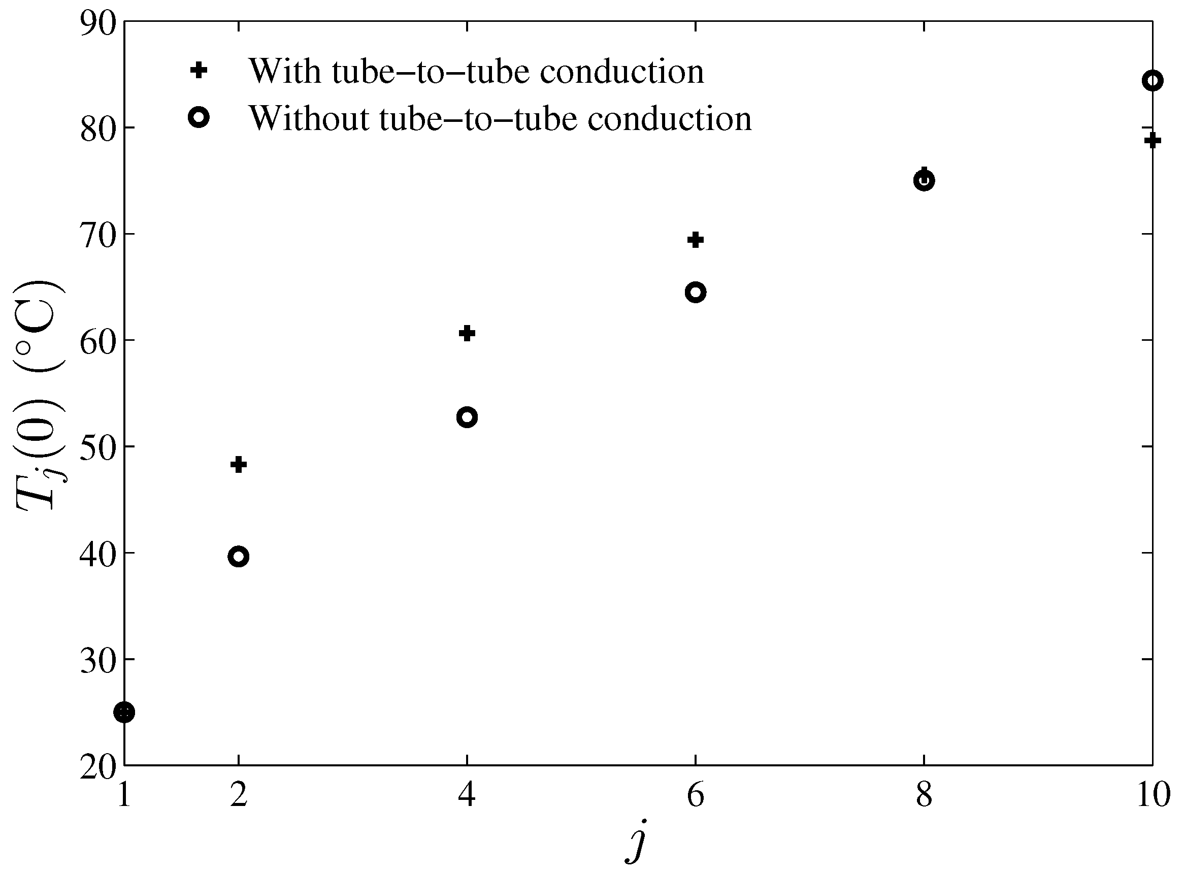
Figure 11 shows the temperature of the fluid inside the tubes at z = 0 for different rows and for two models: one that neglects and one that considers tube-to-tube heat conduction. From this figure, it is possible to visualize how tube-to-tube heat conduction has the effect of evening out the fluid temperature: it raises the in-tube fluid temperature of the first tube rows, but it decreases the in-tube fluid temperature of the final rows, and with it the outlet temperature, such that the global effect of tube-to-tube heat conduction is to reduce the thermal performance of the solar collector.

4. Conclusions

This study demonstrates the existence of tube-to-tube heat conduction along the plates of serpentine-type flat-plate solar collectors. The mathematical model presented here differs from standard models in considering possible backflow across the plates of solar panels as a result of temperature gradients of the in-tube fluid temperature of adjacent tubes. The main difference from previous models is that adiabatic fin tip conditions in the mid-distance between the tubes are not applied but the fin base and tip conditions correspond to the temperatures of the tubes to which it connects. This consideration couples the calculation of the temperatures of all rows of pipes in the solar collector. The results of the model indicate that there is tube-to-tube conduction along the absorber plates of the solar collectors. The magnitude of tube-to-tube conduction is highly dependent on the geometric and operational parameters of the device. The most critical parameters are plate thickness and mass flow rate. In addition, it is also affected by other parameters, such as the absorber plate overall heat transfer coefficient, the number of rows of tubes, separation of adjacent tubes, and the tube length. The effect of tube-to-tube conduction is detrimental to the overall heat transfer of the solar collector. The decrease in fluid heat gain due to the tube-to-tube conduction effect can be up to 10%. Tube-to-tube heat conduction tends to even the fluid temperature of different rows of tubes of the device, which is produced by a back heat flow along the plates that reduces the outlet fluid temperature. This investigation gives insights into the values of the geometrical and operational parameters under which tube-to-tube conduction is relevant. Future work related to this type of solar collector may consider ways to reduce tube-to-tube conduction by modifying the geometrical and operational parameters. Another possibility is the use of cut fins to avoid this effect.

Author Contributions

Conceptualization, E.G.M.-M. and R.R.-M.; investigation, E.G.M.-M. and P.G.-Z.; supervision, R.R.-M. and P.G.-Z.; validation, R.R.-M.; writing—original draft preparation, F.G.P.-G. and R.R.-M.; writing—review and editing, F.G.P.-G. and P.G.-Z. All authors have read and agreed to the published version of the manuscript.

Funding

This research received no external funding.

Data Availability Statement

The original contributions presented in the study are included in the article, further inquiries can be directed to the corresponding author.

Conflicts of Interest

The authors declare no conflicts of interest.

Abbreviations

The following abbreviations are used in this manuscript:
Cin-tube fluid specific heat (J/Kg·K)
A c collector absorber plate surface area (m2)
D i tube inner diameter (m)
D o tube outer diameter (m)
d z tube differential length (m)
F c collector heat removal factor
glength of tube–plate contact strip (m)
jrow number
h i in-tube convective heat transfer coefficient (W/m2·K)
kthermal conductivity of tubes and plates (W/m·K)
k f thermal conductivity of the in-tube fluid (W/m·K)
Llength of each straight section of pipe (m)
m ˙ in-tube fluid mass flow rate (kg/s)
Nnumber of straight sections of pipe
Qtotal heat absorbed by the in-tube fluid (W)
q c o n t heat absorbed by the tube from adhered plate strip (W)
q j rate of heat transfer from absorber plate to j-th tube (W)
q j heat leaving tube j in the direction of tube j 1 (W)
q j + heat leaving tube j in the direction of tube j + 1 (W)
q t u b heat transferred along the plates (W)
Rratio of heat transfer rates with and without tube-to-tube conduction along the plates
R T resistance to heat transfer per unit length between the contact point of the tube–plate and the in-tube fluid (K·m/W)
S S net solar irradiation absorbed by the plate (W)
tplate thickness (m)
T j j-th tube fluid temperature (°C)
T p plate temperature (°C)
T j w j-th tube–plate contact strip temperature (°C)
T i n fluid inlet temperature (°C)
T o u t fluid outlet temperature (°C)
U L absorber plate overall heat transfer coefficient (W/m2·K)
wdistance between adjacent tubes centerline (m)
zaxial position along the pipe measured from inlet (m)
T ambient air temperature (°C)
N u D i inner tube diameter-based Nusselt number
R e D i inner tube diameter-based Reynolds number
P r inner tube fluid Prandtl number
f        smooth pipe Darcy–Weisbach friction factor
η d fin efficiency of pipe as extended surface
θ j j-th tube dimensionless tube–plate contact strip temperature
δ i tube thickness (m)
ψ j j-th tube dimensionless fluid temperature
Ψ vectorial expression of dimensionless fluid temperature
Θ vectorial expression of dimensionless tube–plate contact strip temperature
ν kinematic viscosity of in-tube fluid (m2/s)

References

  1. Tian, Y.; Zhao, C.Y. A review of solar collectors and thermal energy storage in solar thermal applications. Appl. Energy 2013, 104, 538–553. [Google Scholar] [CrossRef]
  2. Raja, A.; Natarajan, R.; Gaikwad, P.R.; Basil, E.; Borse, S.D.; Sundaraj, M. Heat enhancement in solar flat plate collectors—A review. J. Therm. Eng. 2024, 10, 773–789. [Google Scholar] [CrossRef]
  3. Merembayev, T.; Amirgaliyev, Y.; Kunelbayev, M.; Yedilkhan, D. Thermal Loss Analysis of a Flat Plate Solar Collector Using Numerical Simulation. Comput. Mater. Contin. 2022, 73, 4627–4640. [Google Scholar] [CrossRef]
  4. Shamsul Azha, N.I.; Hussin, H.; Nasif, M.S.; Hussain, T. Thermal performance enhancement in flat plate solar collector solar water heater: A review. Processes 2020, 8, 756. [Google Scholar] [CrossRef]
  5. Koholé, Y.W.; Fohagui, F.C.V.; Tchuen, G. Flat-plate solar collector thermal performance assessment via energy, exergy and irreversibility analysis. Energy Convers. Manag. 2022, 15, 100247. [Google Scholar]
  6. Freegah, B. Numerical and experimental analysis of the flat plate solar water heater systems’ thermal performance. Heat Transfer 2023, 52, 1118–1141. [Google Scholar] [CrossRef]
  7. Mokhlif, N.D.; Eleiwi, M.A.; Yassen, T.A. Experimental evaluation of a solar water heater integrated with a corrugated absorber plate and insulated flat reflectors. AIMS Energy 2023, 11, 522–539. [Google Scholar] [CrossRef]
  8. Hassan, Z.; Mahmood, M.; Ahmed, N.; Saeed, M.H.; Khan, R.; Abbas, M.M.; Abdelsalam, E. Techno-economic assessment of evacuated flat-plate solar collector system for industrial process heat. Energy Sci. Eng. 2023, 11, 2185–2201. [Google Scholar] [CrossRef]
  9. Balakrishnan, R.; Chellasamy, G.; Bojan, V.B.; Machakalai, R.K. Empirical investigation and performance evaluation of flat-plate solar water heating systems: A comparative analysis with and without heat exchangers. Z. FüR Phys. Chem. 2025, 239, 1013–1032. [Google Scholar] [CrossRef]
  10. Rahimi-Ahar, Z.; Khiadani, M.; Rahimi Ahar, L.; Shafieian, A. Performance evaluation of single stand and hybrid solar water heaters: A comprehensive review. Clean Technol. Environ. Policy 2023, 25, 2157–2184. [Google Scholar] [CrossRef]
  11. Vengadesan, E.; Gnanasekaran, K. Comprehensive performance analysis of a flat plate solar water heating system featuring a dual-inlet modified absorber. Discov. Sustain. 2025, 6, 489. [Google Scholar] [CrossRef]
  12. Tang, X.; Tan, C.; Liu, Y.; Sun, C.; Xu, S. Numerical Analysis on Heat Collecting Performance of Novel Corrugated Flat Plate Solar Collector Using Nanofluids. Sustainability 2024, 16, 5924. [Google Scholar] [CrossRef]
  13. Mahakud, J.; Kundu, B. Two-Dimensional Analysis of Absorber Plates in Solar Collectors with a Nonlinear Plate Temperature at the Tube Section. Energies 2024, 17, 5979. [Google Scholar] [CrossRef]
  14. Duffie, J.A.; Beckman, W.A. Solar Engineering of Thermal Processes, 2nd ed.; Wiley Interscience: New York, NY, USA, 1991. [Google Scholar]
  15. Lund, K.O. General thermal analysis of serpentine-flow flat-plate solar collector absorbers. Sol. Energy 1989, 42, 133–142. [Google Scholar] [CrossRef]
  16. Eisenmann, W.; Vajen, K.; Ackermann, H. On the correlations between collector efficiency factor and material content of parallel flow flat-plate solar collectors. Sol. Energy 2004, 76, 381–387. [Google Scholar] [CrossRef]
  17. Kroeger, P.G. Performance deterioration in high effectiveness heat exchangers due to axial conduction. Adv. Cryog. Eng. 1967, 12, 363–372. [Google Scholar]
  18. Mondt, J.R. Correlating the effects of longitudinal heat conduction on heat exchanger performance. ASME Heat Transf. Div. 1980, 10, 123–134. [Google Scholar]
  19. Chiou, J.P. The effect of longitudinal heat conduction on crossflow heat exchangers. ASME J. Heat Transf. 1978, 100, 346–351. [Google Scholar] [CrossRef]
  20. Chiou, J.P. The advancement of compact heat exchanger theory considering the effects of longitudinal heat conduction and flow nonuniformity. ASME Heat Transf. Div. 1980, 10, 101–121. [Google Scholar]
  21. Heun, M.K.; Crawford, R.R. Longitudinal fin conduction in multipass cross-counterflow finned-tube heat exchangers. ASHRAE Trans. 1994, 100, 382–389. [Google Scholar]
  22. Romero-Méndez, R.; Sen, M.; Yang, K.T.; McClain, R.L. Effect of tube-to-tube conduction on plate-fin and tube heat exchanger performance. Int. J. Heat Mass Transf. 1997, 40, 3909–3916. [Google Scholar] [CrossRef]
  23. Singh, V.; Aute, V.; Radermacher, R. Numerical approach for modeling air-to-refrigerant fin-and-tube heat exchanger with tube-to-tube heat transfer. Int. J. Refrig. 2008, 31, 1414–1425. [Google Scholar] [CrossRef]
  24. Singh, V.; Aute, V.; Radermacher, R. Investigation of effect of cut fins on carbon dioxide gas cooler performance. HVAC&R Res. 2010, 16, 513–527. [Google Scholar] [CrossRef]
  25. Ding, W.K.; Fan, J.F.; He, Y.L.; Tao, W.Q.; Zheng, Y.X.; Gao, Y.F.; Song, J. A general simulation model for performance prediction of plate fin-and-tube heat exchanger with complex circuit configuration. Appl. Therm. Eng. 2011, 31, 3106–3116. [Google Scholar] [CrossRef]
  26. Sarfraz, O.; Bach, C.K.; Bradshaw, C.R. Discrete modeling of fin-and-tube heat exchangers with cross-fin conduction functionality. Int. J. Refrig. 2019, 104, 270–281. [Google Scholar] [CrossRef]
  27. Sarfraz, O.; Bach, C.K.; Bradshaw, C.R. A novel technique for computationally efficient consideration of cross-fin conduction in fin-and-tube heat exchanger models. Int. J. Refrig. 2019, 107, 73–83. [Google Scholar] [CrossRef]
  28. Sarfraz, O.; Bach, C.K.; Bradshaw, C.R. Validation of advanced fin-and-tube heat exchanger models with cross-fin conduction functionality. Int. J. Refrig. 2020, 116, 70–81. [Google Scholar] [CrossRef]
  29. Saleem, S.; Bradshaw, C.R.; Bach, C.K. Validation of a multi-circuit heat exchanger model for evaluating the effect of refrigerant circuitry on cross-fin conduction in evaporator mode. Int. J. Refrig. 2021, 131, 623–633. [Google Scholar] [CrossRef]
  30. Garcia, J.C.S.; Giannetti, N.; Varela, D.A.B.; Varela, R.J.; Yamaguchi, S.; Saito, K.; Berana, M.S. Design of a Numerical Simulator for Finned-Tube Heat Exchangers with Arbitrary Circuitry. Heat Transf. Eng. 2021, 43, 1675–1693. [Google Scholar] [CrossRef]
  31. Macchitella, S.; Colangelo, G.; Starace, G. Performance prediction of plate-finned tube heat exchangers for refrigeration: A review on modeling and optimization methods. Energies 2023, 16, 1948. [Google Scholar] [CrossRef]
  32. Incropera, F.P.; DeWitt, D.P. Fundamentals of Heat and Mass Transfer, 4th ed.; Wiley: New York, NY, USA, 1996. [Google Scholar]
  33. Gnielinski, V. New equations for heat and mass transfer in turbulent pipe and channel flow. Int. Chem. Eng. 1976, 16, 359–367. [Google Scholar]
  34. Dayan, M. High Performance in Low-Flow Solar Domestic Hot Water Systems (No. DOE/SF/15303-53). Master’s Thesis, Universty of Wisconsin, Madison, WI, USA, 1997. [Google Scholar]
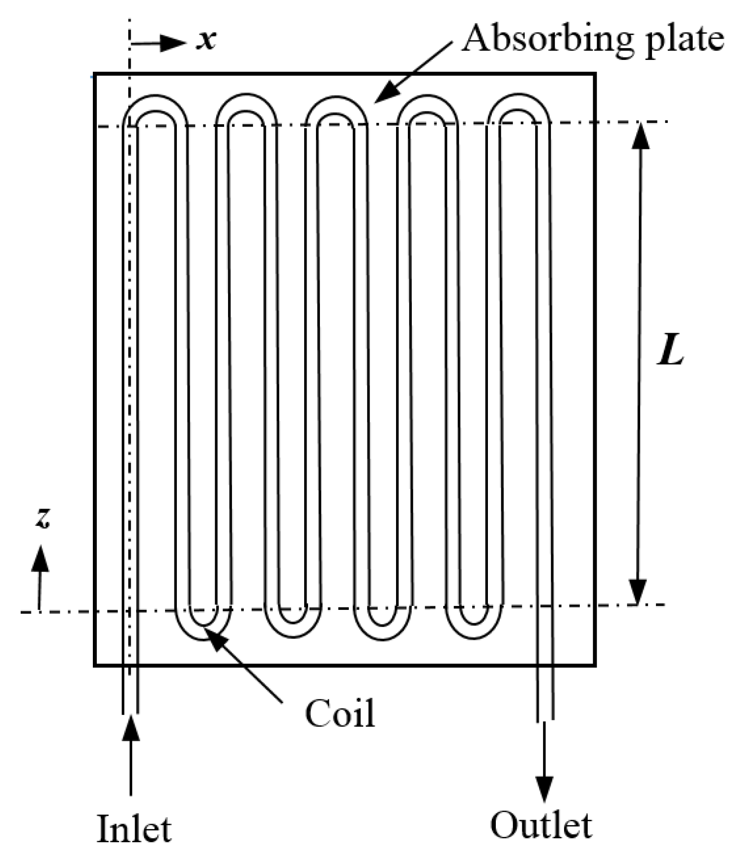
Figure 1. Serpentine type plate-fin tube solar collector.
Energies 18 04360 g001
Figure 2. Geometric dimensions of a plate-fin tube solar collector.
Energies 18 04360 g002
Figure 3. Schematic representation of a plate-fin tube solar collector.
Energies 18 04360 g003
Figure 4. Comparison of results of collector heat removal factor F R vs. m ˙ / A c , using the model presented here (∘) and with the finite-difference technique used by [34] (+).
Energies 18 04360 g004
Figure 5. Variation of tube-to-tube conduction as a function of plate thickness, R vs. t. All other parameters are fixed as in Table 1.
Energies 18 04360 g005
Figure 6. Variation of tube-to-tube conduction as a function of adjacent tubes separation, R vs. w. All other parameters are fixed as in Table 1.
Energies 18 04360 g006
Figure 7. Variation of tube-to-tube conduction as a function of absorber plate overall heat transfer coefficient, R vs. U L . All other parameters are fixed as in Table 1.
Energies 18 04360 g007
Figure 8. Variation of tube-to-tube conduction as a function of in-tube fluid mass flow rate, R vs. m ˙ . All other parameters are fixed as in Table 1.
Energies 18 04360 g008
Figure 9. Variation of tube-to-tube conduction as a function of straight sections of tube length, R vs. L. All other parameters are fixed as in Table 1.
Energies 18 04360 g009
Figure 10. Variation of tube-to-tube conduction as a function of number of tube rows, R vs. N. All other parameters are fixed as in Table 1.
Energies 18 04360 g010
Figure 11. In-tube fluid temperature at row j, T j ( 0 ) different rows; T 1 ( 0 ) is the inlet to the solar collector; T 10 ( 0 ) is the outlet of the solar collector; w = 0.025 m; all other parameters are fixed as in Table 1.
Energies 18 04360 g011
Table 1. Typical geometric and operational parameters of commercial coiled flat solar collectors.
SymbolDescriptionValueUnits
U L Absorber plate overall heat transfer coefficient5.0W/m2· K
D i Inner diameter of tubes0.0065m
D o Outer diameter of tubes0.0075m
LLength of straight sections of tubes1.857m
tThickness of absorber plate0.0005m
wSpacing between adjacent tubes0.075m
gPlate contact length between tubes and plate0.00375m
NNumber of tube rows of coil10
kThermal conductivity of plates and tubes400W/m·K
m ˙ Mass flow rate of water0.001kg/s
ν Kinematic viscosity of water0.000001m2/s
k f Thermal conductivity of water0.628W/m·K
CSpecific heat of water4180J/kg·K
S S Net solar irradiation absorbed by the plate700W/m2
Disclaimer/Publisher’s Note: The statements, opinions and data contained in all publications are solely those of the individual author(s) and contributor(s) and not of MDPI and/or the editor(s). MDPI and/or the editor(s) disclaim responsibility for any injury to people or property resulting from any ideas, methods, instructions or products referred to in the content.