Article

Modification of Short-Channel Structures Towards Heat Transfer Intensification: CFD Modeling

1
Institute of Chemical Engineering, Polish Academy of Sciences, Bałtycka 5, 44-100 Gliwice, Poland
2
Faculty of Civil Engineering and Architecture, Opole University of Technology, Katowicka 48, 45-061 Opole, Poland
*
Author to whom correspondence should be addressed.
Energies 2025, 18(16), 4343; https://doi.org/10.3390/en18164343
Submission received: 5 May 2025 / Revised: 8 August 2025 / Accepted: 11 August 2025 / Published: 14 August 2025
(This article belongs to the Special Issue Computational Fluid Dynamics (CFD) for Heat Transfer Modeling)

Abstract

In this paper, we present the results of heat transfer studies on short-channel structured packing in chemical reactors. Heat transfer coefficients, streamlines, and fluid temperatures were determined using CFD (Computational Fluid Dynamics). CFD simulations were performed for three modified short-channel structures, in which the front of the walls was rounded to eliminate inlet vortices and the outlet was modified (in three versions) to minimize outlet vortices that disturb the fluid flow. CFD simulations for a classic short-channel structure with straight walls were also performed. The results proved that modified structures experienced significantly more intensive heat transport compared to classic structures. Among the tested modifications, the most promising was Modification 1, for which the Nusselt number increased from 65% to 15% depending on the structure length and the Reynolds number. Additionally, for all modifications considered, there was no inlet vortex, which significantly reduced the transport intensity in the classic structure. Further down the channel, the transport intensity was similar for all structures, including the classic structure. The smoothest flow at the outlet of the structure was observed for Modification 1.

1. Introduction

Currently, catalytic monolithic reactors are commonly used as automotive exhaust afterburners; their success does not exclude numerous other industrial and environmental applications [1]. These monoliths, initially made of ceramics (cordierite), were soon made of materials like graphite, alumina, and metals [2,3]. The monolith consists of numerous straight, parallel capillary channels. The channels’ transversal dimensions are a few millimeters in size (from 4 mm to less than 1 mm). As channels are usually a dozen centimeters long, developed laminar flow often exists inside [4,5]. A positive feature of the developed laminar flow is low flow resistance [5]. However, the heat (mass) transport takes place via conduction (diffusion); thus, it is significantly less intense than convection. The dimensionless Sherwood and Nusselt numbers are constant and not dependent on the flow velocity (Reynolds number). This seriously reduces the reaction rate, rendering mass transport of the reactants to the catalyst surface insufficient [6]. Hence, the main advantage of monoliths is their low flow resistance, but at the same time, they have low heat (mass) transfer, which is their main disadvantage. The problem of insufficient heat and mass transport in monolithic reactors is frequently discussed. Several works can be presented here, such as the research of Kolaczkowski et al. [7,8], presenting studies on heat and mass transport and chemical reactions in monoliths, as well as the work of Heibel et al. [9], in which an internally finned monolith was used to improve mass transport. Chartre et al. [10] proposed a 3D-printed structure with random packing, providing a certain simplicity for the designed fluid paths to alleviate mass transfer problems.
In the inlet part of the monolith channel, a developing laminar flow occurs, and the heat (mass) transport coefficients are much higher than in the developed flow (further down the channel). Figure 1 shows a schematic representation of the theoretical dependence of the local value of the Nusselt number, Nu, on the channel coordinate z. This theoretical dependence [5] at the inlet point (z = 0) tends toward infinity, and further down the channel, it relates to the asymptotic value of the Nusselt number, which depends, among other factors, on the channel shape and boundary conditions and characterizes the fully developed laminar flow. This solution was obtained, however, based on the assumption of a uniform fluid velocity distribution at the channel inlet, with velocity vectors equal and parallel to the channel axis. Due to the constant non-zero thickness of the channel walls (even for very thin walls), such an assumption is not feasible in practice. The necessity of flowing around the wall front forces a component of the velocity vector to appear perpendicular to the channel axis at the channel inlet [11,12]. As a result, a vortex (called the inlet vortex) appears in the inlet of the channel, located in the region where, theoretically, the transport coefficients should be the highest. Unfortunately, the vortex causes reverse fluid flow near the channel wall and screens it from the core of the stream, thus reducing the heat transfer intensity in this region. In such cases, the distribution of the Nusselt number is indicated by a line marked “real” in Figure 1. A little further down the channel, the so-called stream split point (the end of the inlet vortex) occurs; at this point, a small local maximum appears in the local Nusselt number distribution. Generally, the phenomena described above significantly lower the overall transport intensity. The literature addressing the problem of vortices in laminar flow is rather scarce; there are studies aimed at streamlined and classic short channel structures [11,12], a classic short channel structure [13], and a honeycomb monolith [14].
The fundamental book by Shah and London [5] shortening heat (mass) transfer intensification in the case of laminar flow occurring in the monolith channels remedies it, resulting in the so-called short-channel structures proposed in [6,15]. The transport coefficients for these structures are much higher than for monoliths, even by an order of magnitude, and the flow resistances are only slightly higher. Apart from the research results of Kołodziej and Łojewska [6,15] and other studies of the team [13], few works present the use of such an operation to intensify heat and mass transport processes. The article by Wang et al. [16] is notable, in which catalytic combustion of VOCs (Volatile Organic Compounds) was carried out in the diffusion regime using metal monoliths with different channel lengths, including straight or bent channels. Significantly higher conversions were obtained for shorter and additionally bent channels, in which mass transport was much more intensive. Kolb and Hessel [17] discuss the problem of limiting the reaction rate by diffusion to the catalyst and the possibility of shortening the channel to intensify mass transport. Jiang et al. [18] present a plate-type mini-channel heat exchanger reactor with arborescent structures and report enhanced heat transfer for the reactor cooling system with short capillary channels.
However, the above-mentioned effect of inlet vortices is still a significant limitation of the intensification of short-channel structure transport. So-called streamlined structures were invented to facilitate a remedy for the inlet vortex appearance [11,12]. This consists of shaping the channel walls of the structure like an airplane wing profile and is presented in the famous book by Herman Schlichting [19]. The streamlined shapes in the chemical apparatus are not new; the heat exchangers with elliptical tubes have been known for many years, providing lower flow resistance and a more intensive heat transfer rate due to their streamlined shape [20,21]. Veerraju and Gopal [22], in turn, modeled heat and mass transfer for elliptical metal hydride tubes and tube banks. The authors found that the use of elliptical tubes leads to more compact reactors than circular tubes with the same internal hydride volume. Another example is MellapakPlus, a famous structured packing of distillation columns, in which a specific bend of the channels was used. Thanks to this shape, a sudden change in the flow direction was avoided at the contacts of the packing layers, which reduced the flow resistance and allowed for an increase in the column load, and, thus, its efficiency [23,24].
The modern internals of catalytic reactors are presented by Ferroni et al. [25] in the form of periodic open cellular structures (POCSs) with streamlined elliptical struts. The elliptical struts reduce flow resistance and increase the surface for catalyst deposition. The authors report that the POCS shows a twofold larger trade-off index between transport coefficient and pressure drop than the state-of-the-art honeycombs.
The transverse component of the velocity vector near the inlet is, therefore, strongly reduced, and the inlet vortex does not appear. The Nusselt number distribution becomes almost identical to the theoretical predictions (cf. Figure 1). Extensive mass transfer studies for the streamlined structures with a square channel cross-section, including experiments and CFD simulations, are presented in [13]. The results have been compared to those of classic short-channel structures displaying similar dimensions. It was found that, for the classic structure, intense vortices appeared at the inlet, which reduced the heat transport intensity; the transverse distribution of Nusselt numbers showed irregularity and some instability. A similar phenomenon did not occur for the streamlined structures. However, for the streamlined structures, the narrowing in the center of the channel caused a high-speed jet, which resulted in intense outlet vortices and higher gas velocities, as well as irregularities in the transverse distribution of Nusselt numbers. Interestingly, this phenomenon (vortices in the outlet channel region) was significantly less intense for the classic structures. It should be noted that the outlet vortices cause an increase in flow resistance and fluctuation in the heat (mass) transfer.
These phenomena described above inspired the design of a new type of short-channel structure, the inlet of which was rounded (as for streamlined structure—to eliminate inlet vortices), and in the middle, the channel remained straight (with constant dimensions—as in classical structure) to eliminate high-speed jetting occurring in streamlined structures, while the outlet was modified (three modifications were considered) to reduce the unfavorable impact of outlet vortices.

2. Modifications of the Structure Geometries

The proposed geometric modifications mainly concerned the outlet section of the channel or, more precisely, the shape of the channel wall at the outlet. The proposed shapes are shown in Figure 2. The outlet in the wall was alternatively cut perpendicularly to the channel axis (modification 1), cut at an angle of 30° (modification 2), or cut in two steps successively at an angle of 30° and then perpendicularly (modification 3), as shown in Figure 2. The CFD simulations included the modifications 1, 2, and 3, as well as the classic short-channel structure. All the channels have a square cross-section. During the design of all the tested geometries, the following assumptions were made:
  • The dimension of all the square structures (side of the square) is D = 4 mm (the distance of the channel wall axes);
  • The lengths of the structures are L = 3, 6 and 12 mm;
  • All the structures, for a given channel length, have similar specific surface area.
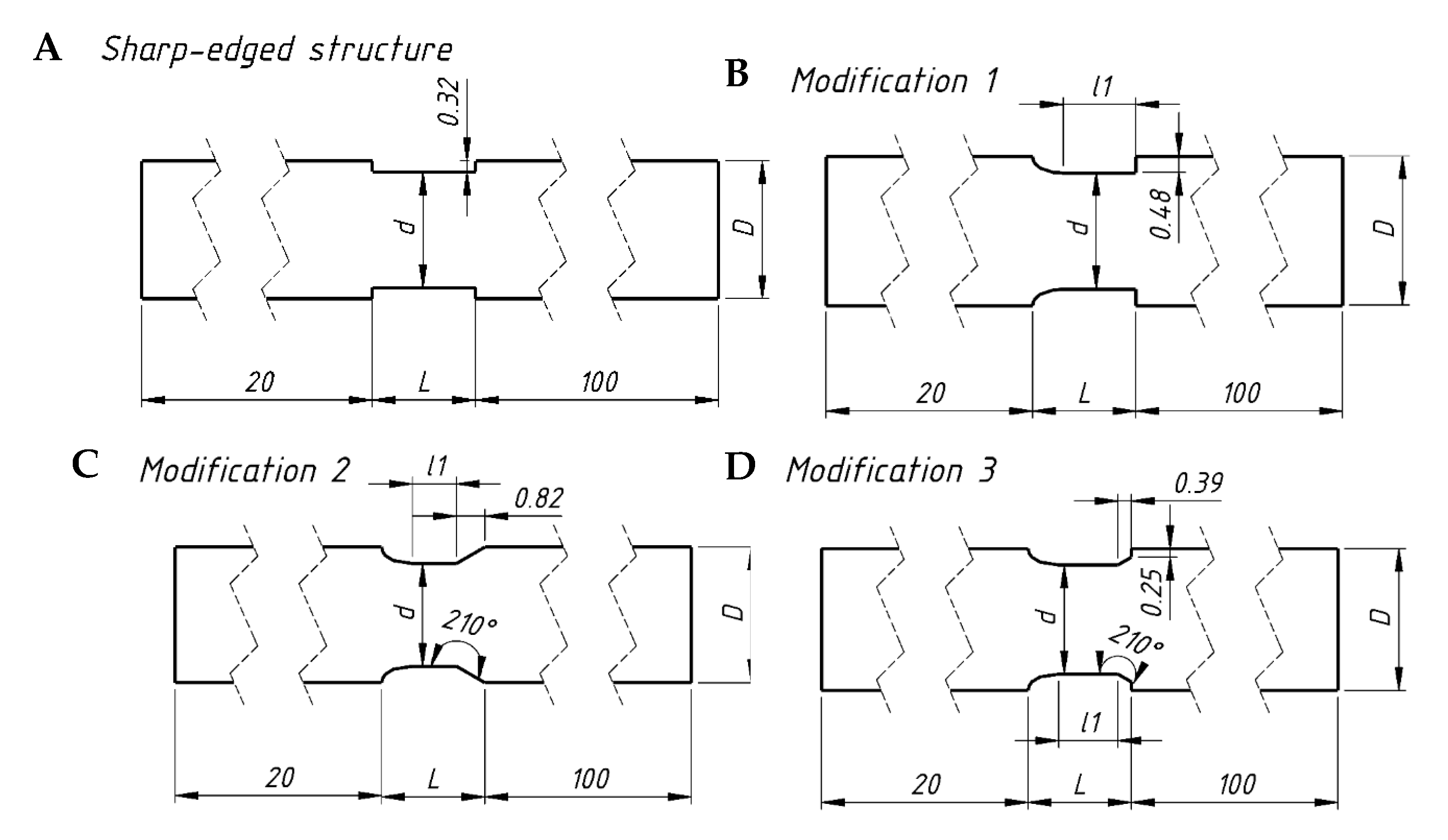
Figure 2. Geometries of the structures studied. (A)—classic short-channel structure; (BD)—modifications No. 1, 2, 3, respectively.
Energies 18 04343 g002
It should be noted that the real structure corresponds to a section of length L. The geometric parameters of the studied structures are listed in Table 1 and include specific surface area (Sv), void fraction (ε), hydraulic diameter (dh = 4ε/Sv), channel length (L), length and dimension (square side) of the narrowest section of the channel (l1, d), and dimension of inlet section (D).

3. Experiments

The heat transfer experiments were conducted for a classical short-channel structure at 3, 6, and 12 mm (denoted as “classic exp.”). The structures were made of AISI 316 steel via the SLM (selective laser melting) method (SLM 50, Realizer, Borchen, Germany). The morphological parameters of the structures are also gathered in Table 1 (data source: Metrotom 1500, Zeiss, Oberkochen, Germany).
The structures were tested using air under ambient conditions, for superficial air velocity v within 0.2–4 m·s−1. The test section of the reactor (home-made) was rectangular, 30 × 45 mm. The metal structures were heated using a strong electric current (Power Supply EA-PS 9080-340, EA Electro-Automatic GmbH, Viersen, Germany) flowing directly through them (Joule effect), ensuring constant heat flux at the structure surface, which corresponds to the H1 boundary condition according to Shah and London [5]. The maximum applied current, Imax, was 290 A, while the maximum voltage, Umax, was no more than 2 V. Air temperature was measured by six thermocouples, three placed before the structure tested and three downstream. The structure temperature was measured by eight thermocouples (four at the inlet and four at the outlet side), with an accuracy of 0.2 K. The thermocouples were attached to the structure with epoxy glue, which ensures excellent thermal conductivity and complete electrical insulation. The logarithmic value of the temperature difference ΔTm between the structure surface and the flowing air was 10–20 K.
The heat transfer coefficient α (W·m−2K−1) was calculated according to the equation:
α = Q F · T m
where Q—heat stream exchanged (W); F—heat exchange surface area (m2); ΔTm—logarithmic mean temperature (K). The Nusselt number Nu was defined as
N u = α · d h λ
where λ is thermal conductivity (W·m−1·K−1). The Reynolds number is defined as
R e = v d h ρ ε η
where v is superficial velocity (m·s−1), ρ is density (kg·m−3), ε is structure porosity, η is viscosity (Pa·s).

4. CFD Modeling

The numerical solution of differential equations describing fluid behavior, based on assumed boundary conditions, enables the visualization of fluid flow and accompanying transport phenomena.
The CFD model of the studied case is based on the universal equations [26] of conservation of mass (Equation (4), momentum for constant density, ρ, and viscosity, μ, (Equation (5)), and energy (Equation (6)).
ρ t + 𝛻 ρ v = 0
ρ D v D t = 𝛻 p + μ 𝛻 2 v + ρ g
ρ c p D T D t = λ 𝛻 2 T
where cp is specific heat; g is body force; t is time; and τ is the stress tensor.
BC:
At inlet velocity = constant;
At inlet temperature = constant;
At channel walls, heat flux = constant;
At symmetry walls, shear stress = 0;
At outlet “pressure outlet”, static pressure = 0.
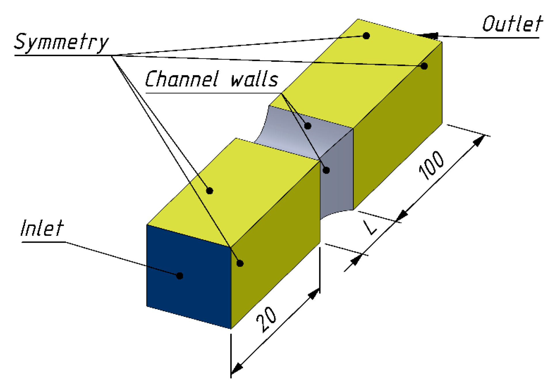
In the studied system, numerical calculations were performed using the Ansys Fluent 2024 R2 software, which operates based on the finite volume method. The calculations were performed in a steady state. The fluid under investigation was air, treated as an incompressible gas with a constant density ρ = 1.225 kg m−3, a constant dynamic viscosity η = 1.7894·10−5 Pa·s, and a thermal conductivity λ = 0.0242 W m−1 K−1. The specific heat was assumed to be 1006.43 J kg−1 K−1. Second-order upwind discretization was used for all equations in the calculations. The “Least-Squares Cell-Based” method was used for gradient calculations, along with the standard pressure–velocity coupling algorithm, SIMPLE (Semi-Implicit Method for Pressure-Linked Equations) [27]. No additional turbulence model was applied in the calculations due to Reynolds number values being below 2000. The calculations were performed on numerical grids composed of tetrahedral elements. Following a preliminary analysis, grids with element counts ranging from 6 million to 24 million were selected for further calculations, depending on the length and type of modification of the structure under investigation. The influence of the independence of the mesh density on the calculation result was assessed based on the change in the calculated value of the Nusselt number. The grids for which the differences in the calculated values of the Nusselt number were below 2% were selected for the calculations. In other words, if the calculation result (Nusselt number) for the denser grid did not differ by more than 2% from the result obtained for the coarser mesh, the denser grid was used in further calculations. The computational domain (Figure 3) was expanded by 20 mm upstream of the channel being studied and by 100 mm downstream (these dimensions are also indicated in Figure 2 and Figure 3). Calculations were performed for three channel lengths, 3, 6, and 12 mm, and for each of the three modifications shown schematically in Figure 2.
The simulations used a boundary condition of constant velocity and temperature at the inlet and a pressure-outlet condition at the outlet. The flow was perpendicular to the inlet surface, and the velocity profile was uniform. The flow velocity was analyzed from 0.1 m s−1 to 4 m s−1. On the “walls” of the computational domain (Figure 3), except for the structures, the symmetry condition was applied, which means that there is no friction on such a surface. The only objects causing flow resistance were the walls of the analyzed channels. Additionally, a constant heat flux of 1500 W m−2 was implemented on the channel walls. The summary of conditions for which the simulations were performed is presented in Table 2.
The criterion for convergence of calculations was the residual value below 10−4 for the continuity equation and 10−7 for the energy equation.

Validation of Numerical Model

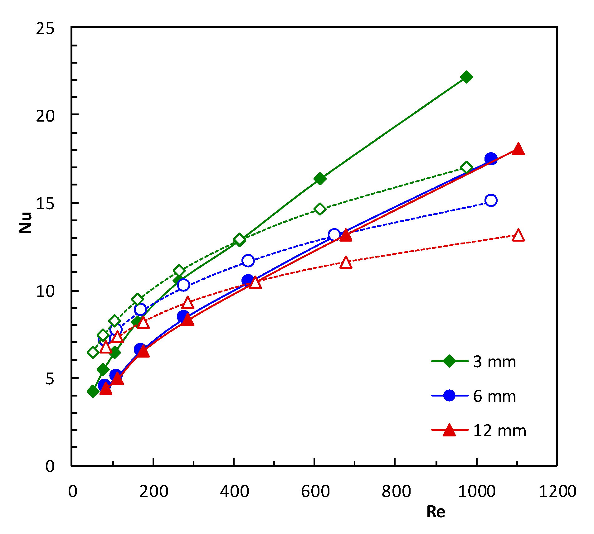
The accuracy of the CFD simulations was verified only for classic short-channel structures. Figure 4 shows the inaccuracy between the CFD and experimental values of Nusselt numbers in the Re number range up to about 1100. CFD simulation predicts experimental data of heat transfer with acceptable agreement (average relative error is equal to 21–27%). It can be mentioned that for the streamlined structures presented in [12], experimental validation of the CFD accuracy was also carried out, obtaining an average difference between experiments and CFD of 13%. Importantly, the same modeling procedure was used in [12] as in this work.
Therefore, it is justified to undertake a detailed analysis of local heat transport phenomena for the proposed structures, which is only possible using modeling methods. Experimental verification of heat transport coefficients (Nu numbers) determined by CFD for other short-channel structures, streamlined and classical, can also be found in the works [11,13].

5. Results and Discussion

5.1. Heat Transfer

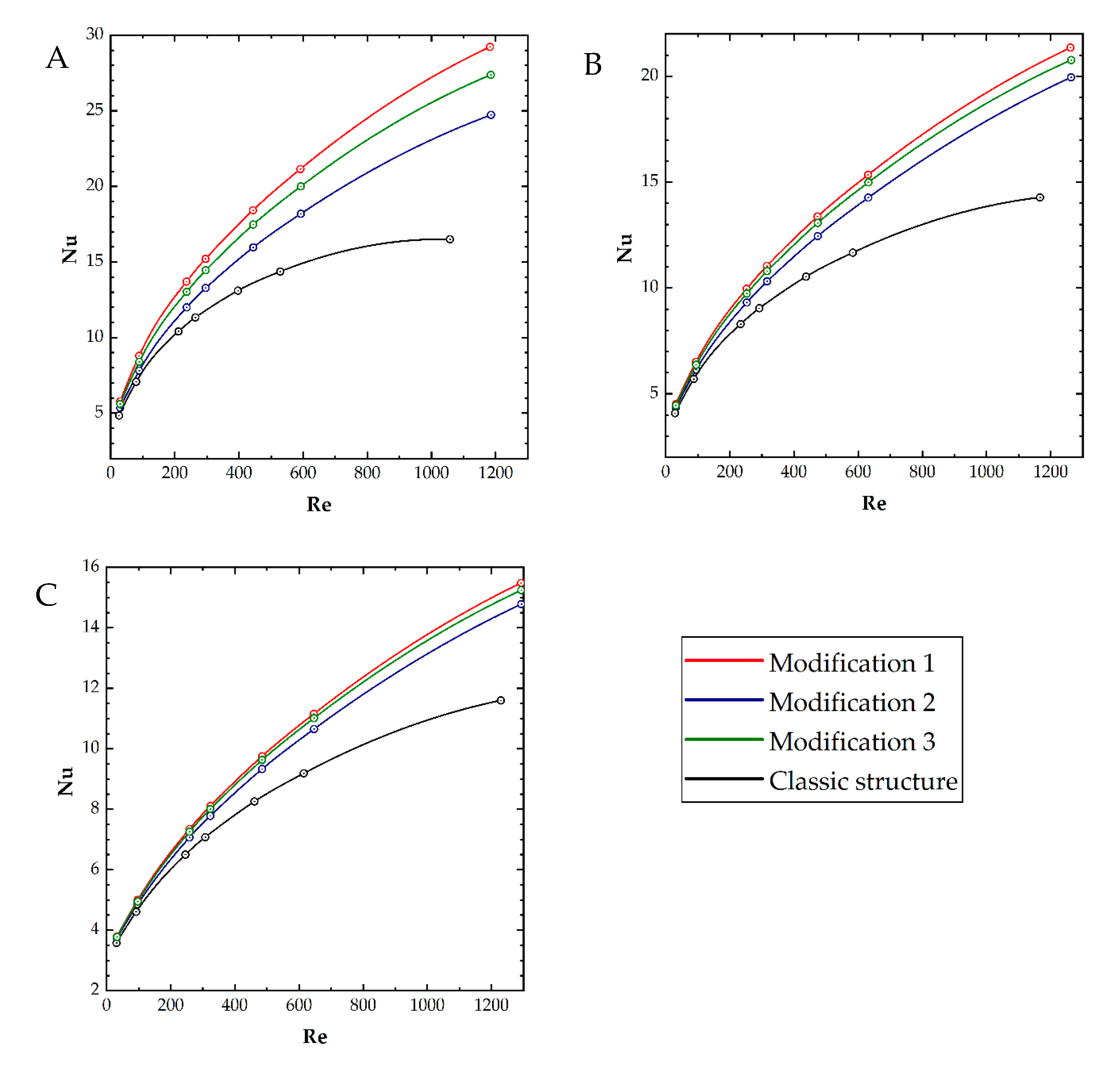
Simulation results of the heat transfer for the structures studied are presented in terms of the Nusselt vs. Reynolds number in Figure 5A–C for the structures 3, 6, and 12 mm long, respectively. Nusselt numbers are averaged for the entire inner channel surface of the structures tested.
According to Figure 5, the characteristics of the three modifications are close to each other. Modification 1 displays the highest values of Nusselt numbers; modifications 3 and then 2 are slightly lower. The classic structure shows the lowest Nusselt numbers of all. The largest differences occur for the shortest structures (L = 3 mm); the differences become lower for the longer channels. For the 12 mm long channels, the differences between modifications 1–3 are almost negligible, while the characteristic of the classic structure lies distinctly lower. For the low Reynolds numbers, all the characteristics are close to each other, while for larger Reynolds numbers, the differences between them increase.
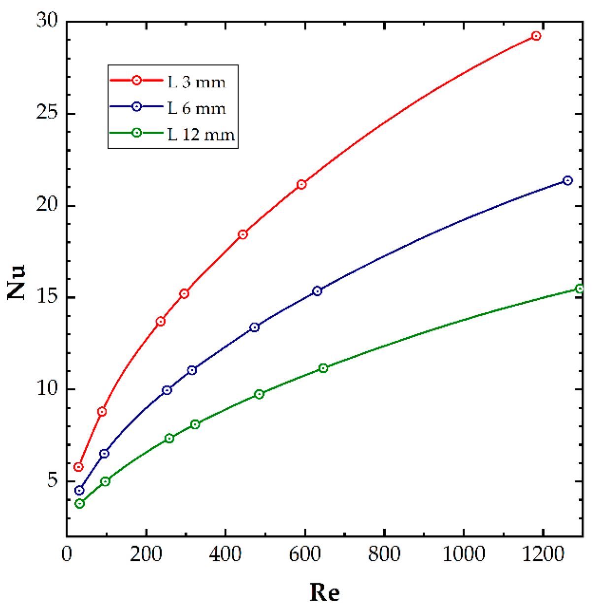
In principle, in all structures, displaying channel lengths from 3 mm to 12 mm, the area of developing laminar flow covers a section of the channel of almost the same length, depending, of course, on the fluid velocity [5]. In this area, heat transport is much more intensive than in the rest of the structure, where the fully developed flow takes place. The share of this area of intense transport, in relation to the entire structure, is the largest in the shortest structures, which thus shows the highest Nusselt numbers. A comparison of the channel length’s influence on the thermal characteristics in terms of Nusselt vs. Reynolds number is shown in Figure 6 for the modified structure No. 1 with channel lengths of 3 mm, 6 mm, and 12 mm; the comparisons for the other structures look similar and differ only in the maximum values of the Nusselt number.
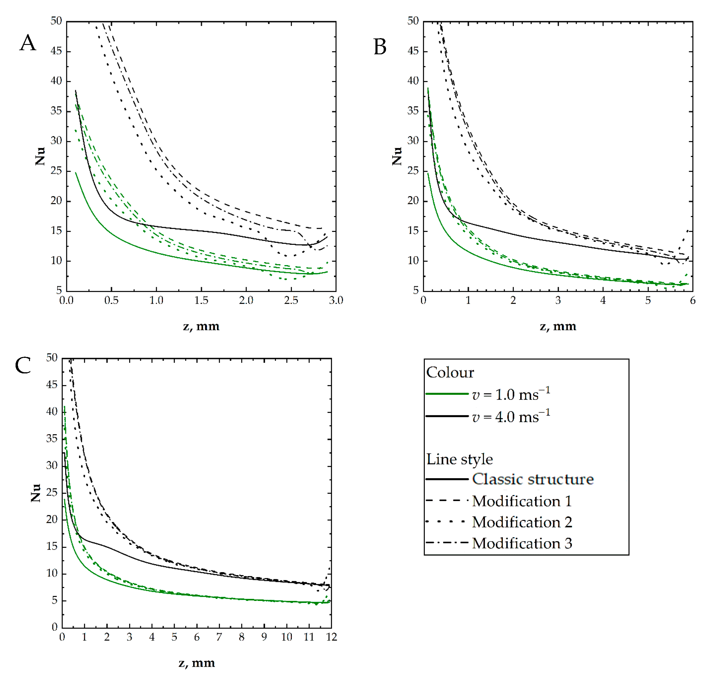
Nusselt number distributions along the channels for all the structures studied are presented in Figure 7. Two air superficial velocities are presented, namely 1.0 m/s and 4.0 m/s, for all three structure lengths. The characteristics for modifications 1–3 are similar for all the lengths. The largest differences are for the shortest structure, but they are not substantial. As in Figure 4 and Figure 5, the highest values of the Nusselt number are shown by modification 1, followed by 3, and the lowest by 2. Near the exit, the Nusselt number distribution for modifications 2 and 3 shows slight, irregular behavior for the gas velocity of 4 m/s. Such behavior was also observed for the shortest classical structure. For the classic structure for both the gas velocities tested, the transport intensity is lower compared to modifications 1–3. This is most distinctly visible near the inlet; further down the channel, Nusselt numbers for all the structures, including the classic one, close in. This behavior is most visible for the longest structures (Figure 7C).

5.2. Flow and Transfer Phenomena

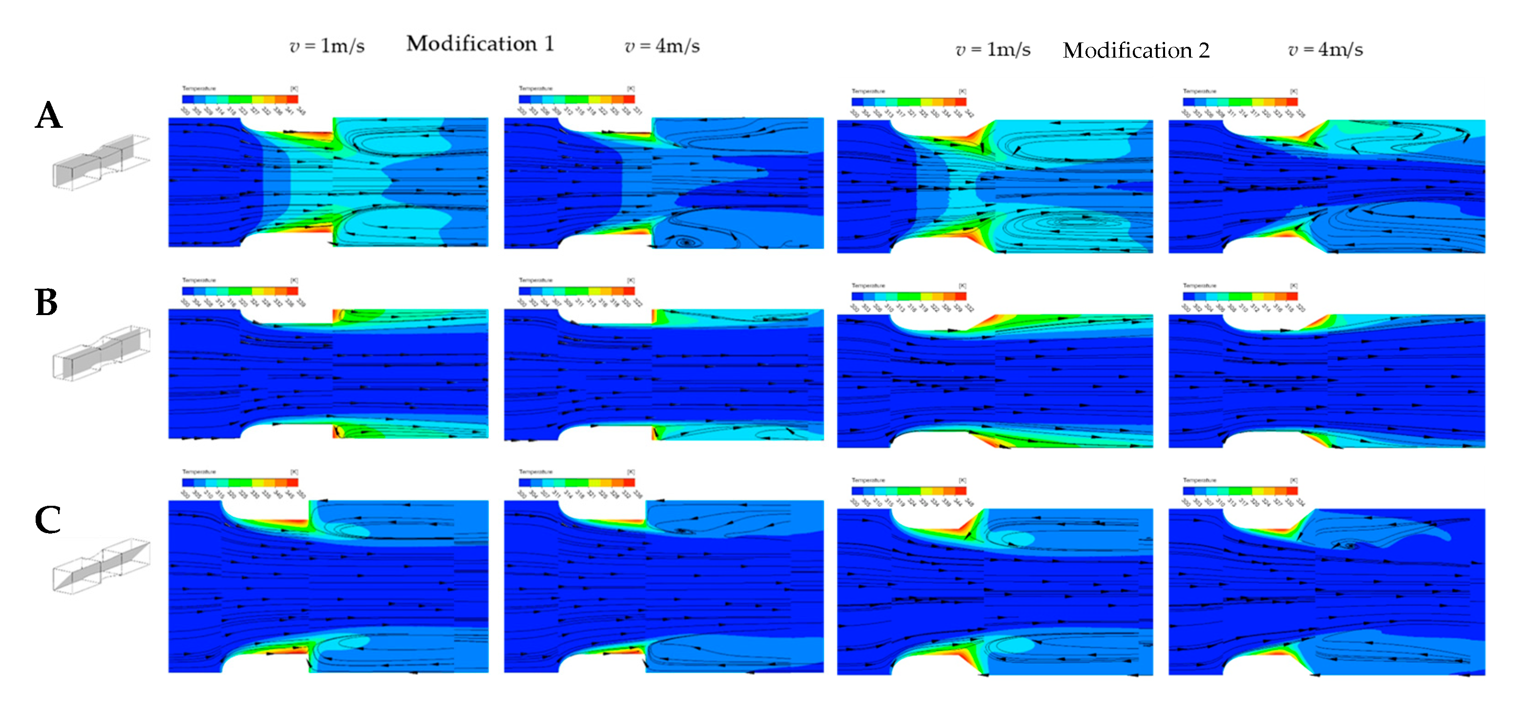
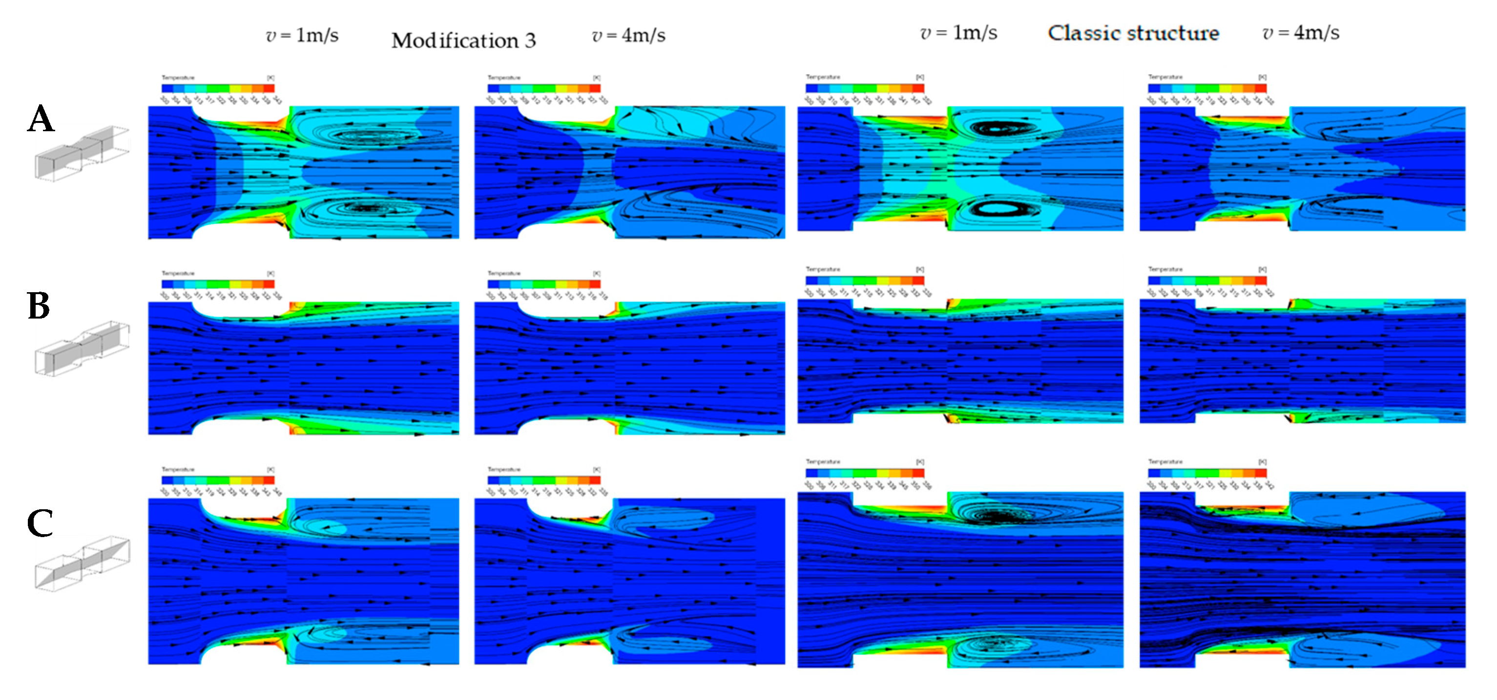
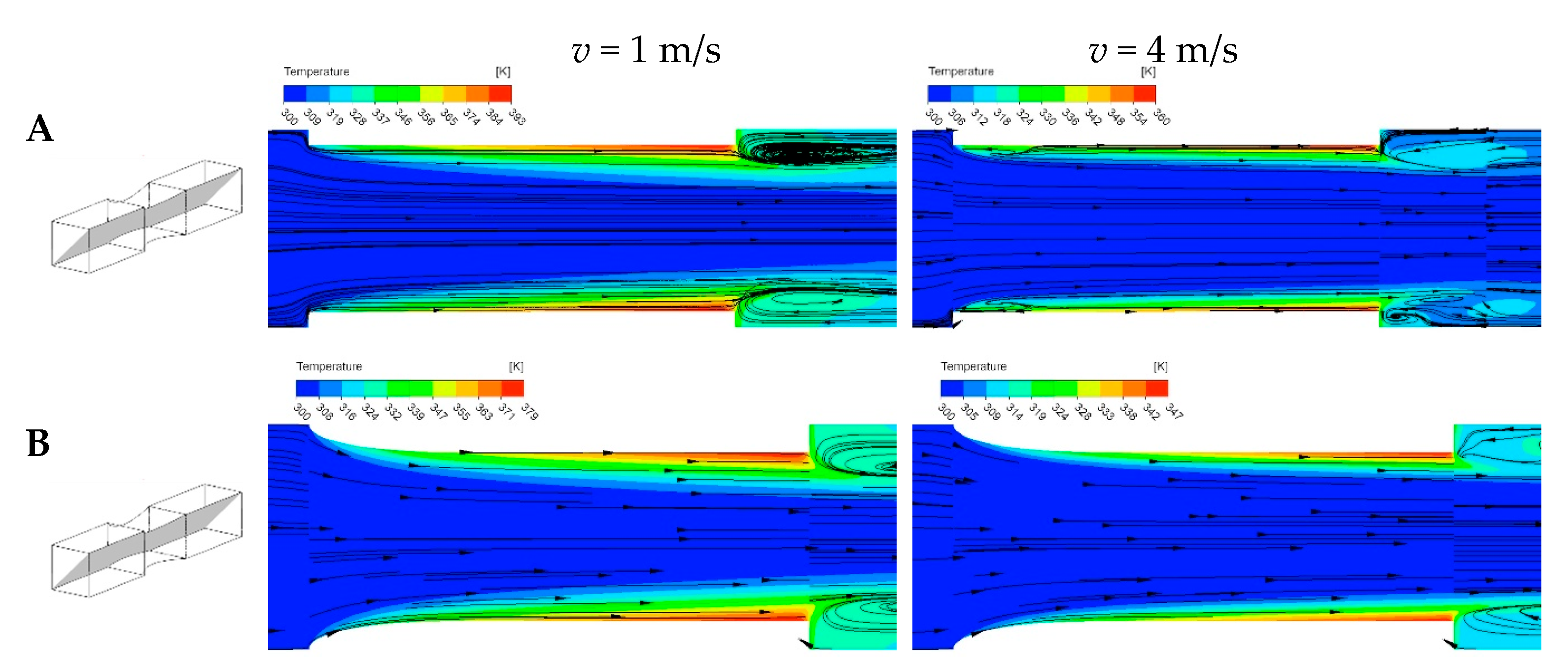
The streamlines and the fluid temperature maps derived using the CFD modeling are presented in Figure 8, Figure 9, Figure 10 and Figure 11. The most general presentation is shown in Figure 8 and Figure 9 for the shortest, 3 mm long structures: modifications 1–3 and the classic one. Note that on the temperature maps, it is possible to assess the temperature gradient on the surface of the structure. The surface is heated with a constant heat flux. This means that, if a cold (blue) fluid region is adjacent to the surface, the temperature gradient is large, so heat transport is intensive and the Nusselt number is high. Warmer areas (green, yellow, red), so-called hot spots, indicate small gradients and, thus, weaker transport (low Nu).
The inlet vortex does not occur for modified structures; in all three modifications, only outlet vortices are observed, regardless of the gas velocities tested. For the classic structure, the inlet vortex occurs; it is distinctly visible for a gas velocity of 4 m/s, much less pronounced for 1 m/s. In the case of all modifications of the modified structures in Figure 8 and Figure 9, we observe intensive heat transport in the inlet part. Indeed, this part of all three modifications has the same geometry. The streamlines are smooth, there are no vortices, and the fluid temperature distribution indicates a significant temperature gradient, i.e., a high heat transfer coefficient.
The conclusions from Figure 8 and Figure 9 relating to the inlet vortices confirm the distributions of local Nusselt numbers presented in Figure 7. These trends, discussed below, are most pronounced for the shortest channels (3 mm), but similar conclusions also apply to longer structures. For all three modifications, the transport coefficients in the inlet region are close to each other and significantly higher than for the classic structure; this tendency is observed for both tested velocities, 4 m/s and 1 m/s. The significantly less intensive heat transport for the classic structure is the result of the inlet vortex interaction.
Further down the channel, the Nusselt numbers for the modified structures and the classic structure decrease and close in on one another. Near the end of the channel, modifications 2 and 3 show a local minimum of the Nusselt number, followed by a slight increase (see Figure 7); this is the effect of the interaction of the outlet vortex with the back wall, inclined at an angle of 30 degrees (see Figure 2). A hot spot appears here in Figure 8 and Figure 9, indicating a lower temperature gradient.
For the classic structure, the Nusselt number increases at the end of the channel, which results from the interaction of the outlet vortex with the back wall, perpendicular to the structure axis (see Figure 7). Heat transport is weaker here, especially for lower fluid velocities. The heat transport intensity is highest in the axial plane of the channel and lowest near the corners. The comparison of temperature maps in the axial plane of the channel in Figure 8 and Figure 9 shows that the highest temperature gradient, and thus the most intensive heat exchange, occurs for modification 1, is weaker for 3, and is even weaker for 2; heat transport is the least intensive for the classic structure. This observation agrees with Figure 4, Figure 5 and Figure 7.
At the end of the structure and beyond it, an outlet vortex is visible in all cases. This vortex affects the rear surface of the structure. For modification 1, this interaction is the least intensive; it visibly supports the heat transport from the rear surface of the structure, as evidenced by its temperature, lower compared to the inner surface of the channel near the outlet. This phenomenon is most pronounced near the corners of the channel, and less intense in the axial plane. For modification 2, the gradient (and thus heat transport) on the rear surface is much smaller. For modification 3 (Figure 9), the outlet vortex affects the rear wall more intensively than for modification 2: this wall is partly perpendicular to the channel axis and, similarly to modification 1, ensures more intensive heat transport.
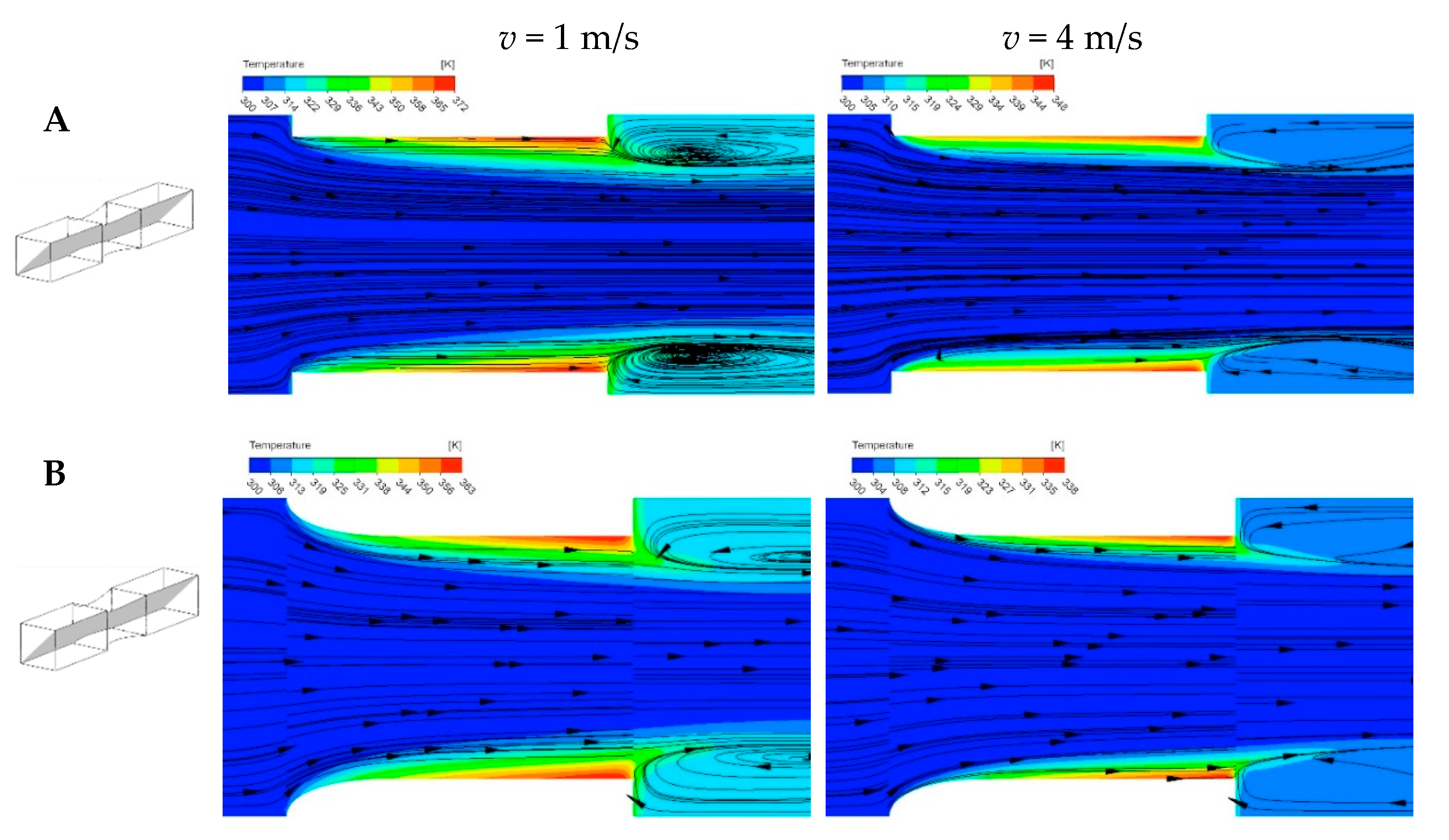
For the longer structures (6 mm and 12 mm long), only exemplified pictures of streamlines and temperature maps are presented in Figure 10 and Figure 11 for the classic structure and modification 1. The plane diagonal of the channel was shown there. Figure 10 and Figure 11 confirm the conclusions presented above regarding the 3 mm long structures. A decreasing temperature gradient is visible along the channel, which is confirmed by the Nusselt number distributions in Figure 7. The outlet vortices are slightly more intense for the classic structure; here, the difference is smaller than for the shortest structures. The outlet vortex enhances heat transfer from the rear wall, as evidenced by the slight increase in the Nusselt number at the end of the channel (see Figure 7). As for the 3 mm long structures, the inlet vortices do not occur for modification 1 but are visible for the classic structure.

6. Conclusions

The results of heat transport in the modified short-channel structured internals of reactors are presented in this paper. All presented results were obtained using CFD simulations.
  • The Nusselt numbers for modifications 1–3 are higher than for the classic short-channel structure. The results for the modified structures are close to each other; the most intensive heat transport is shown by modification 1, then 3, and finally 2.
  • Heat transfer is particularly intensive for the modified structures in the inlet part of the channel when compared to the classic structure. This is a result of the lack, for the modified structures, of inlet vortices that weaken heat transport in the inlet region, theoretically, transport phenomena should be the most intensive. The lack of inlet vortices is visible on the temperature and streamline maps. On the contrary, the inlet vortices are visible for the classic structure, especially for the velocity of 4 m/s. These vortices isolate the channel wall near the inlet from the main fluid flow, thus weakening the heat transfer intensity.
  • Intensive outlet vortices appear in all structures, modified and classic. In the rear of the channel, the temperature gradient decreases. The outlet vortices intensify heat transfer on the back surface of the structures, where the gradient is slightly larger.
  • The heat transfer intensity decreases significantly down the channel for all the structures studied.
  • Modification 1 provides the smoothness streamlines, which may explain the observed highest Nu value compared to the other considered modifications.
Future work can include further structure geometry modifications, including channels with other cross-sections (e.g., hexagonal). To verify the potential benefits of these modifications on reactor performance, it is necessary to deposit a catalyst on the structure’s surface and conduct test reactions, such as the combustion of hydrocarbons diluted in air.

Author Contributions

Conceptualization, A.G. and A.K.; methodology, A.K.; software, M.K. and M.I.; validation, M.S.; formal analysis, K.S.; writing—original draft preparation, A.K. and M.K.; writing—review and editing, A.G. and M.I.; visualization, M.S. and K.S. All authors have read and agreed to the published version of the manuscript.

Funding

This research received no external funding.

Data Availability Statement

Data are contained within the article.

Conflicts of Interest

The authors declare no conflicts of interest.

References

  1. Moulijn, J.A.; Kapteijn, F. Monolithic reactors in catalysis: Excellent control. Curr. Opin. Chem. Eng. 2013, 2, 346–353. [Google Scholar] [CrossRef]
  2. Cybulski, A.; Moulijn, J.A. Monoliths in heterogeneous catalysis. Catal. Rev. 1994, 36, 179–270. [Google Scholar] [CrossRef]
  3. Boger, T.; Heibel, A.K.; Sorensen, C.M. Monolithic catalysts for the chemical industry. Ind. Eng. Chem. Res. 2004, 43, 4602–4611. [Google Scholar] [CrossRef]
  4. Williams, J.L. Monolith structures, materials, properties and uses. Catal. Today 2001, 69, 3–9. [Google Scholar] [CrossRef]
  5. Shah, R.K.; London, A.L. Laminar Flow Forced Convection in Ducts: A Source Book for Compact Heat Exchanger Analytical Data; Academic Press: New York, NY, USA, 1978. [Google Scholar]
  6. Kołodziej, A.; Łojewska, J. Short-channel structured reactor for catalytic combustion: Design and evaluation. Chem. Eng. Process. 2007, 46, 637–648. [Google Scholar] [CrossRef]
  7. Bennett, C.J.; Kolaczkowski, S.T.; Thomas, W.J. Determination of heterogeneous reaction kinetics and reaction rates under mass transfer controlled conditions for a monolith reactor. Process Saf. Environ. Protect. 1991, 69, 209–220. [Google Scholar]
  8. Hayes, R.E.; Kolaczkowski, S.T. Mass and heat transfer effects in catalytic monolith reactors. Chem. Eng. Sci. 1994, 49, 3587–3599. [Google Scholar] [CrossRef]
  9. Heibel, A.K.; Heiszwolf, J.J.; Kapteijn, F.; Moulijn, J.A. Influence of channel geometry on hydrodynamics and mass transfer in the monolith film flow reactor. Catal. Today 2001, 69, 153–163. [Google Scholar] [CrossRef]
  10. Chatre, L.; Socci, J.; Adams, S.J.; Denissenko, P.; Cherkasov, N. Design of 3D-printed structures for improved mass transfer and pressure drop in packed-bed reactors. Chem. Eng. J. 2021, 420, 129762. [Google Scholar] [CrossRef]
  11. Sindera, K.; Korpyś, M.; Iwaniszyn, M.; Gancarczyk, A.; Suwak, M.; Kołodziej, A. New streamlined catalytic carriers of enhanced transport properties: Experiments vs CFD. Chem. Eng. J. 2022, 450, 138297. [Google Scholar] [CrossRef]
  12. Korpys, M.; Iwaniszyn, M.; Sindera, K.; Suwak, M.; Gancarczyk, A.; Kolodziej, A. Flow phenomena in laminar flow through streamlined and sharp-edged short monolithic structures. Sci. Rep. 2023, 13, 15742. [Google Scholar] [CrossRef]
  13. Iwaniszyn, M.; Jodłowski, P.J.; Sindera, K.; Gancarczyk, A.; Korpyś, M.; Jędrzejczyk, R.J.; Kołodziej, A. Entrance effects on forced convective heat transfer in laminar flow through short hexagonal channels: Experimental and CFD study. Chem. Eng. J. 2021, 405, 126635. [Google Scholar] [CrossRef]
  14. Zakharov, V.P.; Zolotarskii, I.A.; Kuzmin, V.A. CFD simulation of “gauze pad–honeycomb” catalytic system. Chem. Eng. J. 2003, 91, 249–255. [Google Scholar] [CrossRef]
  15. Kołodziej, A.; Łojewska, J.; Ochońska, J.; Łojewski, T. Short-channel structured reactor: Experiments versus previous theoretical design. Chem. Eng. Process. 2011, 50, 869–876. [Google Scholar] [CrossRef]
  16. Wang, L.; Tran, T.P.; Vo, D.V.; Sakurai, M.; Kameyama, H. Design of novel Pt-structured catalyst on anodic aluminum support for voc’s catalytic combustion. Appl. Catal. A 2008, 350, 150–156. [Google Scholar] [CrossRef]
  17. Kolb, G.; Hessel, V. Micro-structured reactors for gas phase reactions. Chem. Eng. J. 2004, 98, 1–38. [Google Scholar] [CrossRef]
  18. Jiang, S.Y.; Yang, Z.R.; Zhang, J.; Duan, X.Z.; Qian, G.; Zhou, X.G. Development of a mini-channel heat exchanger reactor with arborescent structures for fast exothermic reactions. Ind. Eng. Chem. Res. 2022, 61, 14121–14131. [Google Scholar] [CrossRef]
  19. Schlichting, H. Boundary Layer Theory; McGraw-Hill: New York, NY, USA, 1979. [Google Scholar]
  20. Deepakkumar, R.; Jayavel, S. Air side performance of finned-tube heat exchanger with combination of circular and elliptical tubes. Appl. Therm. Eng. 2017, 119, 360–372. [Google Scholar] [CrossRef]
  21. Arani, A.A.A.; Uosofvand, H. Double-pass shell-and-tube heat exchanger performance enhancement with new combined baffle and elliptical tube bundle arrangement. Int. J. Therm. Sci. 2021, 167, 106999. [Google Scholar] [CrossRef]
  22. Veerraju, C.; Gopal, M.R. Heat and mass transfer studies on elliptical metal hydride tubes and tube banks. Int. J. Hydrogen Energy 2009, 34, 4340–4350. [Google Scholar] [CrossRef]
  23. Moser, F.; Kessler, A. Increased capacity thanks to improved geometry. Sulzer Tech. Rev. 1999, 3, 24. [Google Scholar]
  24. Čmelíková, T.; Valenz, L.; Lyko Vachková, E.; Rejl, F.J. Basic separation efficiency and hydraulic data of MellapakPlus 452.Y structured packing under distillation conditions. Chem. Eng. Res. Des. 2021, 172, 175–185. [Google Scholar] [CrossRef]
  25. Ferroni, C.; Bracconi, M.; Ambrosetti, M.; Groppi, G.; Maestri, M.; Tronconi, E. Periodic open cellular structures with streamlined elliptical struts for the intensification of mass transfer-limited catalytic reactors. Acs Eng. Au 2025, 5, 168–182. [Google Scholar] [CrossRef]
  26. Ferziger, J.H.; Perić, M. Computational Methods for Fluid Dynamics; Springer: Berlin/Heidelberg, Germany, 2002. [Google Scholar]
  27. Patankar, S. Numerical Heat Transfer and Fluid Flow, 1st ed.; CRC Press: Boca Raton, FL, USA, 1980. [Google Scholar]
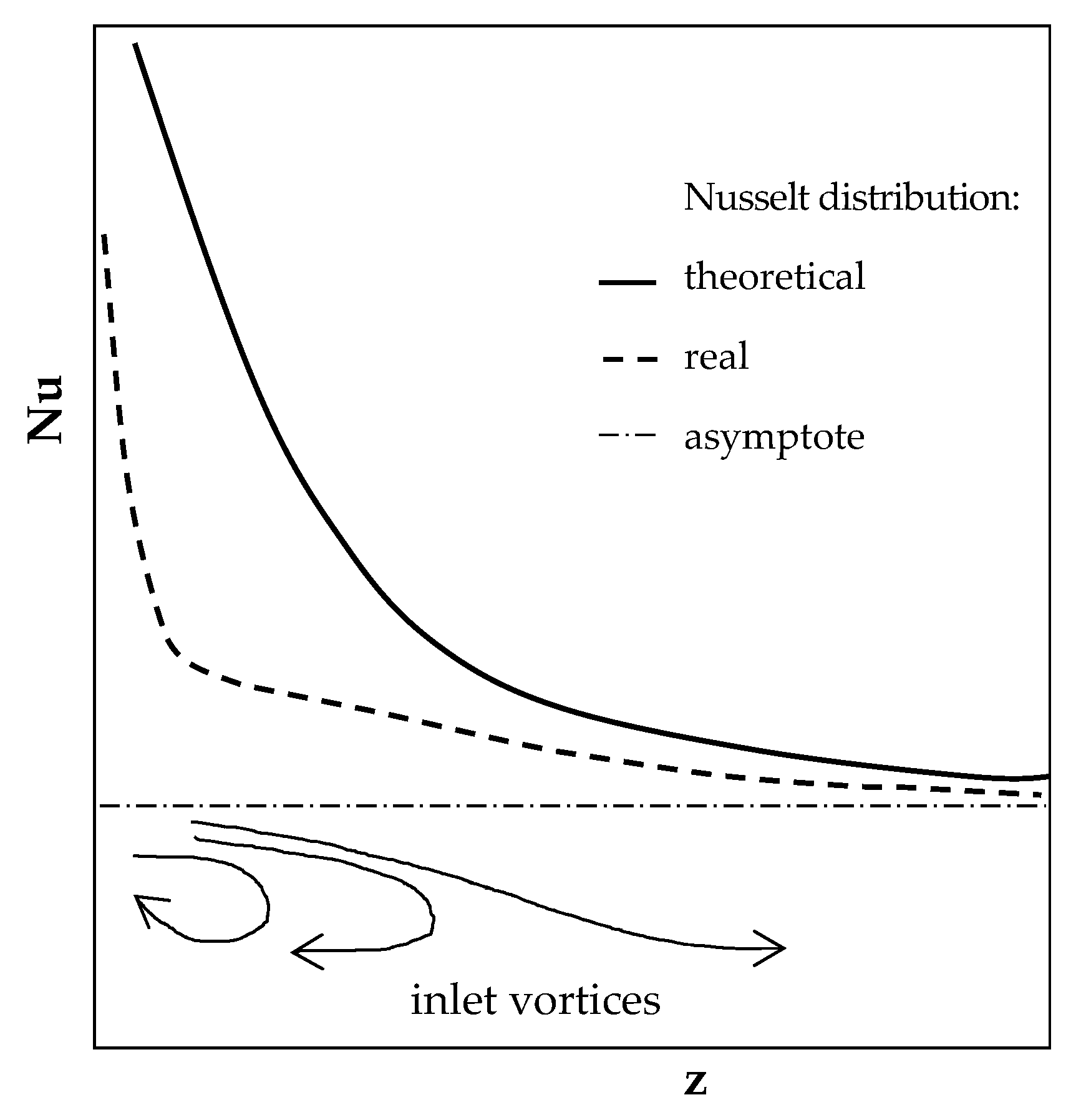
Figure 1. Longitudinal distribution of Nusselt number for the laminar developing flow through capillary channel: theoretical (equal inlet velocity distribution [5]); real—impact of channel wall; asymptote—asymptotic value of Nusselt number for fully developed laminar flow; inlet vortices are shown schematically in the lower part of the figure.
Energies 18 04343 g001
Figure 3. Computational domain diagram.
Energies 18 04343 g003
Figure 4. Accuracy of the CFD modeling—comparison of the experimentally (solid points) derived Nusselt numbers with those obtained from CFD simulations (open points).
Energies 18 04343 g004
Figure 5. Nusselt vs. Reynolds number for the channels: (A) 3 mm long; (B) 6 mm long; (C) 12 mm long.
Energies 18 04343 g005
Figure 6. Nusselt vs. Reynolds number for the modified structure No. 1—comparison of 3 mm, 6 mm, and 12 mm long structures.
Energies 18 04343 g006
Figure 7. Nusselt number distribution along the channels: (A) 3 mm long; (B) 6 mm long; (C) 12 mm long. Nusselt numbers are circumferentially averaged. Velocity v = 1 ms−1 corresponds to Reynolds number: for Modif. 1—Re = 296; Modif. 2—Re = 296; Modif. 3—Re = 296; Classic—Re = 264. Velocity v = 4 ms−1 corresponds to: for Modif. 1—Re = 1183; Modif. 2—Re= 1185; Modif. 3—Re = 1185; Classic—Re = 1057.
Energies 18 04343 g007
Figure 8. Streamlines and fluid temperature maps for the structure modifications 1 and 2: (A) on the plane near the channel wall; (B) on the plane along the axis; (C) on the plane in the diagonal of the channel (see left-hand sketches). Channel length 3 mm. Fluid superficial velocity v = 1 ms−1 corresponds to the Reynolds number: Modif. 1—Re = 296; Modif. 2—Re = 296. Velocity v = 4 ms−1 corresponds to the following: Modif. 1—Re = 1183; Modif. 2—Re = 1185.
Energies 18 04343 g008
Figure 9. Streamlines and fluid temperature maps for the 3 structure modifications and the classic short-channel structure: (A) on the plane near the channel wall; (B) on the plane along the axis; (C) on the plane in the diagonal of the channel (see left-hand sketches). Channel length 3 mm. Fluid superficial velocity v = 1 ms−1 corresponds to the Reynolds number: Modif. 3—Re = 296; Classic—Re = 264. Velocity v = 4 ms−1 corresponds to the following: Modif. 3—Re = 1185; Classic—Re = 1057.
Energies 18 04343 g009
Figure 10. Streamlines and fluid temperature maps for (A) classic structure and (B) structure modification 1, on the plane in the diagonal of the channel (see left-hand sketches). Channel length 6 mm. Velocity v = 1 ms−1 corresponds to the following Reynolds numbers: Modif. 1—Re = 315; Classic—Re = 292. Velocity v = 4 ms−1 corresponds to the following: Modif. 1—Re = 1262; Classic—Re = 1166.
Energies 18 04343 g010
Figure 11. Streamlines and fluid temperature maps for (A) classic structure and (B) structure modification 1, on the plane in the diagonal of the channel (see left-hand sketches). Channel length 12 mm. Velocity v = 1 ms−1 corresponds to the following Reynolds numbers: Modif. 1—Re = 323; Classic—Re = 307. Velocity v = 4 ms−1 corresponds to the following: Modif. 1—Re = 1292; Classic—Re = 1229.
Energies 18 04343 g011
Table 1. Geometric parameters of the structures studied.
TypeL,
m
Sv,
m2/m3
εdh,
m
D,
m
d,
m
l1,
m
Modif. 10.0039260.630.00270.0040.003380.00211
Modif. 29240.650.00280.0040.002990.00128
Modif. 39240.620.00270.0040.003170.00172
Classic10360.710.00270.0040.003370.003
Classic exp.10210.700.0027
Modif. 10.0068680.600.00280.0040.003060.00422
Modif. 28670.610.00280.0040.002850.00339
Modif. 38670.600.00280.0040.002950.00383
Classic9390.710.00300.0040.003370.006
Classic exp.9300.710.0031
Modif. 10.0128470.590.00280.0040.002860.00843
Modif. 28470.590.00280.0040.002750.00761
Modif. 38470.580.00270.0040.002800.00804
Classic8910.710.00320.0040.003370.012
Classic exp.8730.700.0032
Table 2. Range of simulations run.
TypeVelocity at Inlet, m s−1Reynolds NumberTemperature at Inlet, KHeat Flux, W m−2 K−1
Modif. 10.1303001500
0.3893001500
0.82373001500
1.02963001500
1.54443001500
2.05923001500
4.011833001500
Modif. 20.1303001500
0.3893001500
0.82373001500
1.02963001500
1.54443001500
2.05933001500
4.011853001500
Modif. 30.1303001500
0.3893001500
0.82373001500
1.02963001500
1.54443001500
2.05933001500
4.011853001500
Classic0.1263001500
0.3793001500
0.82113001500
1.02643001500
1.53963001500
2.05293001500
4.010573001500
Disclaimer/Publisher’s Note: The statements, opinions and data contained in all publications are solely those of the individual author(s) and contributor(s) and not of MDPI and/or the editor(s). MDPI and/or the editor(s) disclaim responsibility for any injury to people or property resulting from any ideas, methods, instructions or products referred to in the content.