Article

Numerical Analysis of Heat Transfer in a Double-Pipe Heat Exchanger for an LPG Fuel Supply System

Department of Mechanical System Engineering, Gyeongsang National University, 2, Tongyeonghaean-ro, Tongyeong-si 53064, Gyeongsangnam-do, Republic of Korea
*
Author to whom correspondence should be addressed.
Energies 2025, 18(15), 4179; https://doi.org/10.3390/en18154179
Submission received: 3 July 2025 / Revised: 25 July 2025 / Accepted: 2 August 2025 / Published: 6 August 2025
(This article belongs to the Collection Advances in Heat Transfer Enhancement)

Abstract

LPG fuel supply systems are increasingly important for improving energy efficiency and reducing carbon emissions in the shipping industry. The primary objective of this research is to investigate the heat transfer phenomena to enhance the thermal performance of double-pipe heat exchangers (DPHEs) in LPG fuel supply systems. This study investigates the heat transfer performance of a glycol–steam double-pipe heat exchanger (DPHE) within an LPG fuel supply system under varying operating conditions. A computational model and methodology were developed and validated by comparing the numerical results with experimental data obtained from commissioning tests. Additionally, the effects of turbulence models and parametric variations were evaluated by analyzing the glycol–water mixing ratio and flow direction—both of which are critical operational parameters for DPHE systems. Numerical validation against the commissioning data showed a deviation of ±2% under parallel-flow conditions, confirming the reliability of the proposed model. With respect to the glycol–water mixing ratio and flow configuration, thermal conductance (UA) decreased by approximately 11% in parallel flow and 13% in counter flow for every 20% increase in glycol concentration. Furthermore, parallel flow exhibited approximately 0.6% higher outlet temperatures than counter flow, indicating superior heat transfer efficiency under parallel-flow conditions. Finally, the heat transfer behavior of the DPHE was further examined by considering the effects of geometric characteristics, pipe material, and fluid properties. This study offers significant contributions to the engineering design of double-pipe heat exchanger systems for LPG fuel supply applications.

1. Introduction

The use of liquefied natural gas (LNG), liquefied petroleum gas (LPG), and methanol as eco-friendly fuels is increasing as a transitional solution and has attracted attention as a means to achieve emission reduction targets for nitrogen oxides and sulfur oxides [1] until the commercialization of carbon-free ships. Their usage is expected to increase in the coming decades, enhancing energy security and diversity [2]. Stricter regulations are being implemented because of the environmental damage caused by air pollution from ships. With the goal of achieving net-zero carbon emissions to ad-dress climate change resulting from rising global temperatures [3], it is anticipated that zero-carbon ships utilizing eco-friendly fuels such as hydrogen and ammonia will eventually be commercialized. Various technologies such as efficiency improvement and the use of alternative fuels have been proposed to reduce greenhouse gas emissions [4].
Table 1 provides a comprehensive comparison of their key characteristics, including physical properties and storage conditions in LPG and LNG. LPG is easier to store than LNG because it liquefies at higher temperatures (−42 °C at atmospheric pressure) and can be maintained in liquid form under moderate pressures (up to 18 bar at 45 °C). Conversely, LNG requires extremely low temperatures (−162 °C) for liquefaction, though it can be liquefied at ambient temperature when subjected to high pressures [5]. Both fuels significantly reduce emissions of SOx, NOx, PM, and CO2 compared to traditional heavy fuel oil (HFO), while maintaining comparable energy densities. LPG is typically transported either as a gas via pipelines or as a liquid in gas carriers, whereas LNG production involves cooling natural gas to about 1/600 of its original volume, and LPG is reduced to roughly 1/250 of its gaseous volume, facilitating efficient long-distance maritime transport. Both fuels are stored in insulated tanks appropriate to their temperature and pressure requirements.
Recently, the use of fuel supply systems that utilize LPG or LNG along with boil-off gases has increased. Starting with LPG carriers, which currently transport LPG as cargo, large LPG-fueled ships are being equipped with MAN-ES’ ME-liquid gas injection LPG (LGIP) engines, which reduce carbon dioxide emissions by 30% compared to low-sulfur fuel oil ships in preparation for stricter environmental regulations. For LPG carriers de-signed in accordance with the IGC Code, the transition to LPG and LNG propulsion or conversion is relatively straightforward. Both LPG and LNG have emerged as next-generation fuels in the maritime industry, thereby increasing interest in LPG fuel and related technologies during this transitional period [6]. The engine requires the LPG fuel supply temperature to be within the range of 25–45 °C, necessitating the use of a heat exchanger to achieve these conditions. The heat exchanger must provide sufficient heat capacity to satisfy the engine temperature requirements by heating the fuel according to the LPG temperature in the service tank. The heat source for the LPG heat exchanger is steam. However, the direct heat exchange between the steam and LPG within the heat exchanger could compromise the safety of the ship if the heat exchanger is damaged. Therefore, a closed-loop system using glycol antifreeze as an intermediate medium is preferred [7].
The main motives of this research are to improve the energy efficiency and reduce carbon emissions of LPG fuel supply systems in the shipping industry. To achieve this, the study aims to optimize the heat transfer efficiency of double-pipe heat exchangers (DPHEs) by systematically analyzing the effects of the glycol–water mixing ratio and flow direction under various operating conditions. Furthermore, the work is motivated by the need for validated and practical design strategies that can be widely applied to environmentally friendly and efficient LPG fuel supply systems.
The primary types of heat exchangers are plate, shell and tube, tubular, and double-pipe heat ex-changers [8]. Plate heat exchangers are widely used in high-efficiency, compact systems because the two fluids flow crosswise between the plates and have a high heat transfer coefficient relative to the heat exchange area. However, it is difficult to maintain airtightness due to gasket hardening, requires regular maintenance, and is vulnerable to contamination by certain fluids [9]. Shell-and-tube heat exchangers can operate at high pressures and temperatures and have excellent durability, but their overall heat transfer coefficient is relatively low, which increases the heat transfer area and consequently increases the size of the heat exchanger, taking up more space than plate heat exchangers [10]. Tubular heat exchangers are simple and robust structures in which one fluid flows through a single tube or multiple tubes and the other fluid flows through an outer jacket. Easy tube replacement and inspection result in low maintenance costs, but the heat transfer area is small compared to the plate type, so the heat exchange performance per unit area is low, and it may be inefficient when large-scale heat exchange is required. The double-pipe heat exchanger consists of two concentric pipes, and one fluid flows through the inner pipe, and the other fluid flows through the annular space between the two pipes to form two independent channels, thereby facilitating heat exchange. This type of heat exchanger is freely modular, parallel, and series arranged, and is optimal for heat exchange in small pilot plants, ships, etc. Because of these advantages, double-pipe heat exchangers are preferred for glycol heating systems in LPG fuel–powered ships.
A double-pipe heat exchanger comprises two concentric pipes and facilitates heat exchange by allowing one fluid to flow through the internal pipe and the other through the annular space between the two pipes, resulting in two independent channels. This type of heat exchanger is compact and cost-effective [11]. Because of these advantages, double-pipe heat exchangers are preferred for glycol heating systems in LPG fuel–powered ships.
There are two main approaches to evaluating and verifying the performance of key components: experimental methods and numerical analysis. Due to limitations in time and cost, numerical methods are often employed. Furthermore, advancements and improvements in numerical analysis techniques have led to increased accuracy and reliability, making numerical simulations a widely used tool in design analysis across various applications.
Recent studies have demonstrated the effectiveness of numerical approaches in marine engineering applications. Mai and Yoon [12] conducted numerical investigations on motion response of tankers at varying vertical centers of gravity, showcasing the capability of computational methods in predicting complex vessel dynamics. Similarly, Kim et al. [13] performed combined experimental and numerical studies on free surface wave characteristics generated by submerged body movements, validating the accuracy of numerical predictions against experimental data. In heat transfer applications, Lee and Choi [14] utilized numerical analysis to investigate fin and temperature effects on frost formation in ambient air vaporizers, demonstrating the versatility of computational approaches in thermal system analysis.
Research on double-pipe heat exchangers (DPHE) started in the 1940s [15], and since then, researchers have continuously investigated the heat transfer characteristics and thermal performance of DPHEs under various conditions. Cohen and Johnson [16] studied the dynamic characteristics of DPHEs and reported that the DPHE component characteristics can be easily determined through the frequency response. Aicher and Kim [17] investigated that nozzle induced cross flow markedly boosts heat transfer in DPHE. Dezfoli and Mehrabian [18] compared experiments with standard correlations, finding shell-side heat transfer rates 3.4 times lower than tube-side in parallel flow and 1.5 times lower in counter flow.
Moradi et al. [19] conducted that increasing Reynolds and Graetz numbers and carboximethyl cellulose concentration enhances heat transfer for pseudoplastic fluids. Naphon [20] found that smaller twist ratios yield higher Nusselt numbers, with inlet temperature exerting a strong effect. Choudhari and Taji [21] studied coil wire inserts made of various materials and noted that copper inserts provided the highest heat transfer enhancement compared to other materials. Zhang et al. [22] investigated that combined helical fins and vortex generators significantly raise heat-transfer coefficients. Further studies by Barga and Saboya [23], Zamzamian et al. [24], and Prasad et al. [25] explored the effects of different fin configurations, nano fluids, and twisted tapes on the heat transfer in DPHEs under various conditions, reporting significant enhancements and increased heat transfer coefficients.
In particular, various key research cases utilizing numerical analysis can be found in LPG fuel propulsion systems. Han et al. [26] performed performance analysis of constant-speed LPG engines using computational methods, providing insights into engine optimization strategies. Furthermore, Heo et al. [8] developed predictive models for heat transfer performance in complex heat exchangers specifically designed for LNG Fuel Gas Supply System (FGSS) development, demonstrating the critical role of advanced heat exchanger design in marine fuel systems.
In addition, Marzouk et al. [27] recently numerically demonstrated that the Nusselt number can be improved up to 242% and the thermal–hydraulic performance and exergy efficiency can be significantly improved at the same time through the DPHE design applying the extended fins. Alkalibi et al. [28] proposed an extended fin-based DPHE for waste heat recovery from industrial exhaust gas, and clearly demonstrated the heat transfer performance improvement of up to 32% compared to the conventional structure and the waste heat recovery effect through nano fluids and structural optimization. As such, the extended fin-based design is a study that can greatly expand the DPHE heat exchange area and application range.
Kavitha R et al. [29] investigated the impact of copper oxide (CuO) nano fluids on heat transfer performance in a double-pipe heat exchanger at varying inlet temperatures. Venkatesh B et al. [30] employed a hybrid optimization scheme that coupled a genetic algorithm with Grey Relational Analysis to design a counter-flow DPHE, showing that the simultaneous tuning of tube diameters leads to an annular gap. Esfandyari et al. [31] performed artificial neural networks and adaptive neuro-fuzzy inference system models combined with particle swarm optimization to predict the thermal performance of a counter-flow double-pipe heat exchanger. Both models showed high accuracy, with the artificial neural networks–particle swarm optimization model achieving over 94.84% correlation. Mustafa M et al. [32] performed an experimental investigation on U-bend double-pipe heat exchangers charged with a 0.1 vol % MgO–water nano fluid and reported a 35% rise in the convective heat-transfer coefficient compared with the base fluid, with bend curvature and nanoparticle loading.
Most existing research on heat exchangers has primarily focused on conventional shell-and-tube systems, often addressing specific and narrowly defined applications. Similarly, investigations of double-pipe heat exchangers (DPHEs) have predominantly concentrated on heat transfer characteristics involving single-phase fluids—such as water or oil—or single transport media without the quantitative effects of fluid conditions. Although numerous studies have utilized numerical simulations to assess heat exchanger performance, relatively few have conducted validation using commissioning test data—an essential step for ensuring the reliability and practical applicability of the simulation results. Moreover, comprehensive investigations that compare and optimize both parallel- and counter-flow configurations while simultaneously accounting for multiple parameters—such as glycol concentration, flow rate, turbulence model, and pipe material—remain notably limited in the existing literature.
The present study aims to address these scientific and research gaps by quantitatively investigating the influence of fluid conditions on heat exchanger performance, specifically focusing on the UA value and thermal efficiency through a validated numerical approach. To ensure the reliability of the simulation, the computational model was rigorously validated using commissioning test data. This research represents a significant scientific contribution by conducting the first comprehensive multivariable analysis of a glycol–water dual-fluid DPHE system. In contrast to previous studies limited to single-variable or single-fluid analyses, the present work concurrently evaluates the effects of mixing ratio, flow direction, piping material, and geometric characteristics. This integrated approach offers a robust framework for performance optimization and future model development.
In this study, the heat transfer characteristics and performance of a double-pipe heat exchanger (DPHE) used in an LPG fuel supply system were analyzed under various operating conditions. A computational model and method were developed and validated by comparing the numerical results with the experimentally obtained data from the commissioning tests. Additionally, the effects of the turbulence model and parametric studies were examined by analyzing the glycol–water mixing ratio and flow direction, both of which are critical operating parameters for DPHE. Finally, the heat transfer phenomenon is analyzed by considering various variables such as the geometric characteristics of the DPHE used in the LPG fuel supply system, piping material, and fluid conditions, thereby differentiating it from existing studies.

2. Background

Figure 1 illustrates the LPG fuel supply system, designed to stably supply LPG fuel stored in the fuel tank at the pressure, temperature, and flow rate required by the engine. The system’s primary components include a fuel pump that delivers LPG fuel and a fuel heater that adjusts the fuel temperature to meet the engine’s operational specifications.
LPG is stored in the fuel supply tank at approximately 0 bar(g) and −52 °C. It is then compressed and heated through the fuel supply line, enabling it to be supplied to the engine at approximately 50 bar(g) and 25–45 °C.
The LPG stored in the fuel supply tank is transferred to the fuel supply line through the fuel supply pump installed in the tank. It is then pressurized to the engine’s fuel supply pressure through the pressurization pump and subsequently heated to the required engine temperature in the fuel heater before being supplied to the engine. The LPG fuel pressure is consistently maintained at 54 bar to ensure stable operation.
If the pressure detected by the pressure sensor exceeds the preset value, the system initially reduces the speed of the pressurization pump to lower the pressure. If the pressure remains elevated, a portion of the LPG fuel located at the rear of the pressurization pump is discharged to the return line to decrease the pressure behind the pressurization pump, thereby maintaining operational stability.
The fuel heater utilizes glycol–water as the heating medium, which is a mixture of glycol and fresh water. To maintain a constant supply temperature of LPG fuel at 35 °C, the system continuously monitors the temperature in the fuel supply line. The control valve then adjusts the glycol flow rate according to the detected temperature, ensuring consistent and reliable heating of the LPG fuel
Figure 2 illustrates the glycol–water heating system, designed to stably supply LPG fuel at the temperature required by the engine by exchanging heat between high-temperature glycol–water and low-temperature LPG. This configuration ensures reliable fuel temperature control and consistent performance under varying operating conditions. The system operates as a closed-loop cycle, where glycol–water, cooled through heat exchange in the fuel heater, is directed to the expansion tank. Within the expansion tank, the glycol concentration and circulating flow rate are adjusted as needed. The glycol–water is then pressurized by the supply pump and circulated back to the fuel heater, maintaining a continuous heating cycle.
Integrating a double-pipe heat exchanger into the cycle proves to be more energy-efficient and cost-effective, particularly when utilizing existing onboard facilities. This approach not only reduces operational expenses but also leverages the available infrastructure, making it a practical and sustainable solution for maintaining the required heating conditions.
The glycol–water supplied to the fuel heater exchanges heat with high-temperature steam within the double-pipe heat exchanger, allowing for constant temperature control of the glycol–water. To maintain the LPG fuel temperature at the set value (35 °C), the system uses a three-way control valve to dynamically regulate the flow rate of glycol–water supplied to the LPG fuel heater.
Table 2 presents the operating conditions of the glycol–steam double-pipe heat exchanger (DPHE), which were established based on actual engineering requirements and field measurements from the target LPG fuel supply system. Instead of referring to a universal standard or published guideline, the selected parameters directly reflect the fuel flow rate, steam generation capacity, pressure, and temperature specifications defined for the ME-LGIP engine installed on the reference vessel. In this system, glycol–water with an initial temperature of 35 °C flows through the heat exchanger, where it exchanges heat with steam at 165 °C. As a result, the glycol–water temperature rises to 49.5 °C after heat exchange. To maintain the desired outlet temperature of 49.5 °C, a three-way control valve regulates the flow rate of steam connected to the No. 1 heat exchanger. If the steam outlet temperature on the No. 1 heat exchanger side is detected to be lower than the set value (49.5 °C), the valve adjusts the steam flow rate accordingly to stabilize the temperature. Similarly, the steam temperature at the outlet side of the No. 2 heat exchanger is continuously monitored, and the flow rate of steam injected through the three-way control valve is adjusted as necessary. This control mechanism ensures that both heat exchangers maintain optimal heat transfer performance, allowing the system to consistently meet the required temperature specifications.
The fluid in the inner pipe is a mixture of 50% ethylene glycol and 50% fresh water, and the freezing point is −36.8 °C. The fluid in the outer pipe is general steam. The freezing point of the glycol–water mixture can be adjusted by varying the mixing ratio of ethylene glycol and water. At 20 °C, the viscosity is about 3.5 cP, the specific heat is about 3.5 kJ/kg K, and the heat transfer efficiency is maintained without excessive increase in pumping and pressure drop. It is a ratio commonly used in ship heat exchangers, automotive coolants, and antifreezes, as it avoids the decrease in heat transfer performance that occurs as the concentration of ethylene glycol increases. This characteristic makes the 50–50 ratio particularly suitable for applications requiring efficient heat transfer while maintaining freeze resistance in harsh operating conditions.

3. Numerical Analysis

3.1. Governing Equation

Under steady-state conditions, the governing equations for the control analysis of the internal flow in the heat exchanger are expressed using the continuity equation (Equation (1)), momentum equation (Equation (2)) and the energy equation (Equation (3)). The governing equations are given as (Zhang et al., 2012 [22])
x i ρ u i = 0
x j ρ u i u j = p x i + x j μ + μ t μ i x j + μ j x i
x i u i T = x i μ P r + μ t p r t T x i
where ρ is the density of the fluid, u is the velocity, p is the pressure, μ is dynamic viscosity, μ t is turbulent viscosity, T temperature, and Pr is the Prandtl number.
The heat transfer rate, which is the amount of heat transferred per unit of time in the heat exchange system, is expressed by Equations (4)–(6) [33]
Q h = m h c p h ( T h i T h o )  
Q c = m c c p c ( T c o T c i )
Q a v g = Q = Q h + Q c 2
Q = U A T L M
where, Q is the heat transfer rate, U is the overall heat transfer coefficient, A is the heat transfer inner surface area, and T L M is the logarithmic mean temperature difference expressed as Equation (8)
T L M = ( T h i T c i ) ( T h o T c o ) ln ( T h i T c i / ( T h o T c o ) ] :   parallel   flow         T L M = ( T h i T c o ) ( T h o T c i ) ln ( T h i T c o / ( T h o T c i ) ] :   counter   flow
The heat transfer formula for cylindrical walls of the tube wall was calculated according to Fourier’s law, as shown in Equation (9)
q = 2 π K z l n ( r o r i ) T h T c
where r i is the inner radius of the tube, r o is the outer radius of the tube, K is the thermal conductivity of the tube, z is the heat transfer through the length when the high temperature and low temperature fluid temperatures are considered constant, T h is the temperature of the high temperature fluid, and T c is the temperature of the low temperature fluid.
When heat is transferred through a surface in a specific heat exchange system, the overall heat transfer coefficient (U) serves as a key index that comprehensively represents the heat transfer characteristics both inside and outside the surface. It is utilized to calculate the amount of heat transferred per unit area per unit time, thereby providing a quantitative measure of heat transfer efficiency. The overall heat transfer coefficient reflects the combined characteristics of the heat transfer path both inside and outside the system, accounting for the thermal resistance of various components and materials. This comprehensive representation enables engineers to assess and optimize the thermal performance of heat exchangers, ensuring efficient energy transfer under varying operational conditions. The overall heat transfer coefficient (U) is generally expressed as Equation (10)
U = 1 r o h i r i + 1 h o + l n r o r i     r o k
where U denotes the overall heat transfer coefficient, h denotes the convective heat transfer coefficient inside and outside the surface, and k denotes the thermal conductivity of the heat transfer path.
ε = Q Q m a x
Q m a x = C m i n ( T o T i ) m i n
Q m a x is the maximum possible heat transfer rate for given inlet temperatures of the fluids, and C m i n is the minimum heat capacity rate. The effectiveness ε depends on the heat exchanger geometry, flow pattern (parallel flow, counter flow, cross flow, etc.), and the number of transfers.
N T U = U A C m i n
For any heat exchanger it can be shown that the effectiveness of the heat exchanger is related to a non-dimensional term called the number of transfer units (NTU). Most of these relationships involve the ratio of C r = C m i n C m a x for a single pass heat exchanger in the counter current flow regime is
ε = 1 e x p [ N T U ( 1 C r ) ] 1 C r   e x p [ N T U ( 1 C r ) ]
In the present study, the fluid-conjugated heat transfer inside a heat exchanger was analyzed. To accurately capture the turbulent flow characteristics, two turbulence models were considered: the k-ε turbulence model and the k-ω turbulence model. The k-ε turbulence model and the k-ω turbulence model are both widely used two-equation turbulence models that incorporate transport equations to represent the effects of convection and diffusion of turbulent energy within fluid flow systems. These models were selected to evaluate their effectiveness in predicting heat transfer performance under varying operating conditions.
The k-ε turbulence model is a two-equation model that includes two transport equations to account for the convection and diffusion of turbulent energy. This model calculates the turbulent viscosity by determining the characteristic velocity from the turbulent kinetic energy (k) equation and the characteristic length from the turbulent kinetic energy dissipation rate (ε) equation. The k-ω turbulence model is a two-equation eddy viscosity model that also incorporates convective transport equations for turbulent kinetic energy (k) and its specific dissipation rate (ω). This model is designed to accurately represent the effects of turbulence convection and diffusion within fluid flow systems. It determines the eddy viscosity by calculating the specific dissipation rate (ω) and the turbulent kinetic energy (k), allowing for accurate modeling of near-wall turbulence and flows with strong pressure gradients.
For an incompressible fluid, the turbulent kinetic energy (k) and its dissipation rate (ε) in the k-ε turbulence model are governed by the following transport equations, as shown in Equations (11) and (12):
· ρ k U = · μ t σ k k + 2 μ t E i j E i j ρ ε
· ρ ε U = · μ t σ ε ε + C 1 ε ε k 2 μ t E i j E i j C 2 ε ρ ε 2 k
where E i j is the average strain rate, and C 1 ε , C 2 ε are constants. For the k-ω turbulence model, the eddy viscosity is expressed as a function of the relationship between the turbulent kinetic energy (k) and the specific dissipation rate (ω). It is calculated based on the ratio of dissipation to turbulence intensities, and is defined as
μ t = ρ k ω
The turbulent viscosity μ t is not a physical property but a value that changes depending on the pattern or history of turbulent motion. For an incompressible fluid, k and ω are governed by the following transport Equations (14) and (15):
· ρ k U = · μ + μ t σ k k + P k β * ρ k ω
· ρ ω U = · μ + μ t σ k ω + α ω k P k β ρ ω 2
where P k is the Turbulent kinetic energy generation term, and α is the generation coefficient, a constant that adjusts the generation term in proportion to P k in a particular dissipation rate equation. It is determined by the characteristic length or velocity of the turbulent motion from experiments or observations and is expressed as follows:
ς   = k 1 / 2
l = k 3 / 2 ε  
μ t = C ρ ς l = ρ C μ k 2 ε
The model constants used in the calculation are defined as follows [34]:
C μ = 0.09 , C 1 ε = 1.44 , C 2 ε = 1.92

3.2. Numerical Conditions

The present numerical analysis was designed based on the experimental results of the glycol–steam double-pipe heat exchanger (DPHE) used in the LPG fuel supply system. The analysis considered critical factors such as flow direction, glycol–water mixing ratio, and turbulence models to assess their influence on heat transfer behavior. By systematically evaluating these parameters, the study aimed to accurately predict the system’s performance under practical operating conditions, thereby providing valuable insights for enhancing heat exchanger efficiency and reliability.
Figure 3 shows a sectional view of the DPHE used in the experiment, and Table 3 lists its specifications. The heat exchange section of the double pipe was designed to have a length of 3600 mm for optimizing heat transfer efficiency. For the flow rate conditions in the heat exchanger, the glycol–water flow rate was 1.805 kg/s, and the steam flow rate was 0.025 kg/s. These values were determined based on the operating conditions of the LPG fuel supply system. The glycol–water enters the heat exchanger at an inlet temperature of 35 °C and an operating pressure of 2.0 bar, while the steam enters at an inlet temperature of 165 °C and an operating pressure of 6.0 bar, establishing the thermal conditions for heat transfer within the system.
To analyze the heat transfer of the double-tube heat exchanger, a mixture of 50% of ethylene glycol, 50% of fresh water, and general steam was used. The radiation heat transfer was assumed to be negligible, and the outer tube was considered to be perfectly insulated.
The physical properties of the fluids are listed in Table 4. The physical properties according to the mixing ratio of ethylene glycol to water, as shown in Table 5, indicate that as the mixing ratio of ethylene glycol to water increased, the density and viscosity increased, while the thermal conductivity and specific heat decreased. In the LPG fuel supply system, a mixture of ethylene glycol and fresh water is commonly used as an anti-freeze solution, with glycol ratios of 50% and 60% being the most prevalent. This is because a 50% glycol mixture has a freezing point of −36.8 °C, while a 60% mixture lowers it to −52.8 °C. Although an 80% glycol mixture has a freezing point of −46 °C and remains usable, increasing the glycol ratio beyond 50% is generally unnecessary due to cost considerations. A 50% mixture was sufficient to achieve the desired temperature without the need for higher concentrations. The specific ratio of the antifreeze mixture ensures freeze protection, stable operation of the heat exchanger, and cost efficiency [1,35].
Numerical analysis was conducted using three-dimensional steady-state incompressible turbulent flow conditions based on the fundamental continuity, Navier–Stokes momentum, and energy equations. To obtain a numerical solution of the internal flow field, the k-ε turbulence model was used. The k-ε turbulence model is mainly used in turbulent flow analysis and accurately predicts the eddy-viscosity characteristics over time and the characteristics of flows with a high Reynolds number [22]. The coupled technique was used for pressure and velocity field analysis, and the spatial discretization of the pressure and momentum was performed in the second order.
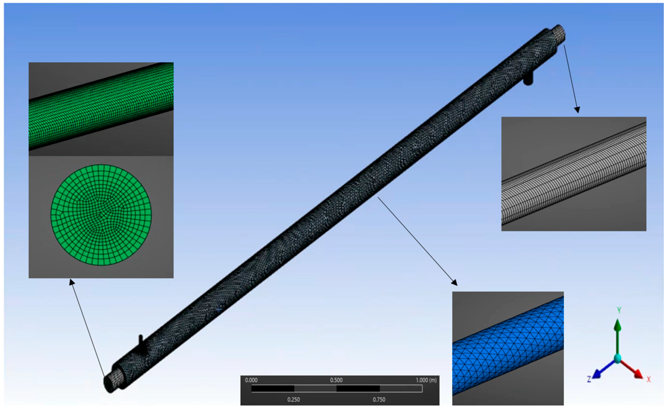
In the double-pipe configuration shown in Figure 4, glycol–water flows through the inner pipe, whereas steam circulates through the outer pipe, allowing effective heat transfer between the two fluids, and the two fluids flow in opposite directions.
δ i = X c o a r s e r ,     n X f i n e r ,   n X f i n e r ,   n 2
Figure 4 shows the numerical model of the DPHE. In this numerical study, after comparing and analyzing hexahedral and tetrahedral meshes, mesh dependency verification was performed. Considering the mesh dependency and the suitability of the heat exchanger geometry, the final mesh was set to element mix. As shown in the close-up picture of Figure 4, hexahedral elements were mainly used for the glycol–water flow section with a relatively simple cylindrical tube cross section, and tetrahedral elements with excellent shape suitability were applied for the steam flow section with a curved shape and abrupt cross-sectional change on the inlet/outlet side.
A mesh independence study was performed to ensure accuracy of the numerical result for the numerical calculation for the flow in GW outlet temperature This study was carried out by successively increasing the mesh size with a structured grid—a coarse grid with lower number of nodes, and a fine grid with higher number of nodes. The results were represented by δ (the difference between the calculated values using different grids), which were accumulated using root-mean-square values of the calculated results using Equation (23).
Table 6 shows the value of δ for GW outlet temperature used in the numerical study under different mesh conditions. There are variations in the solution between the different mesh conditions; the resulting variation is within 0.1%. Therefore, a mesh configuration consisting of approximately 260,000 nodes was employed to balance computational cost and solution accuracy. All the governing equations and boundary conditions were solved using the finite volume method of the commercial CFD package Fluent (ANSYS Fluent, 2024 R2).

4. Results

4.1. Numerical Validation Study

Numerical validation was performed by comparing the numerical results with experimental data obtained from the LPG fuel supply system. A validated numerical scheme was employed to conduct parametric studies, focusing on determining the effects of the turbulence model, glycol–water mixing ratio, and flow direction on the system’s performance. The validation process involved comparing the numerically obtained values with the experimentally measured values for the outlet temperature of the glycol–steam double-pipe heat exchanger (DPHE).
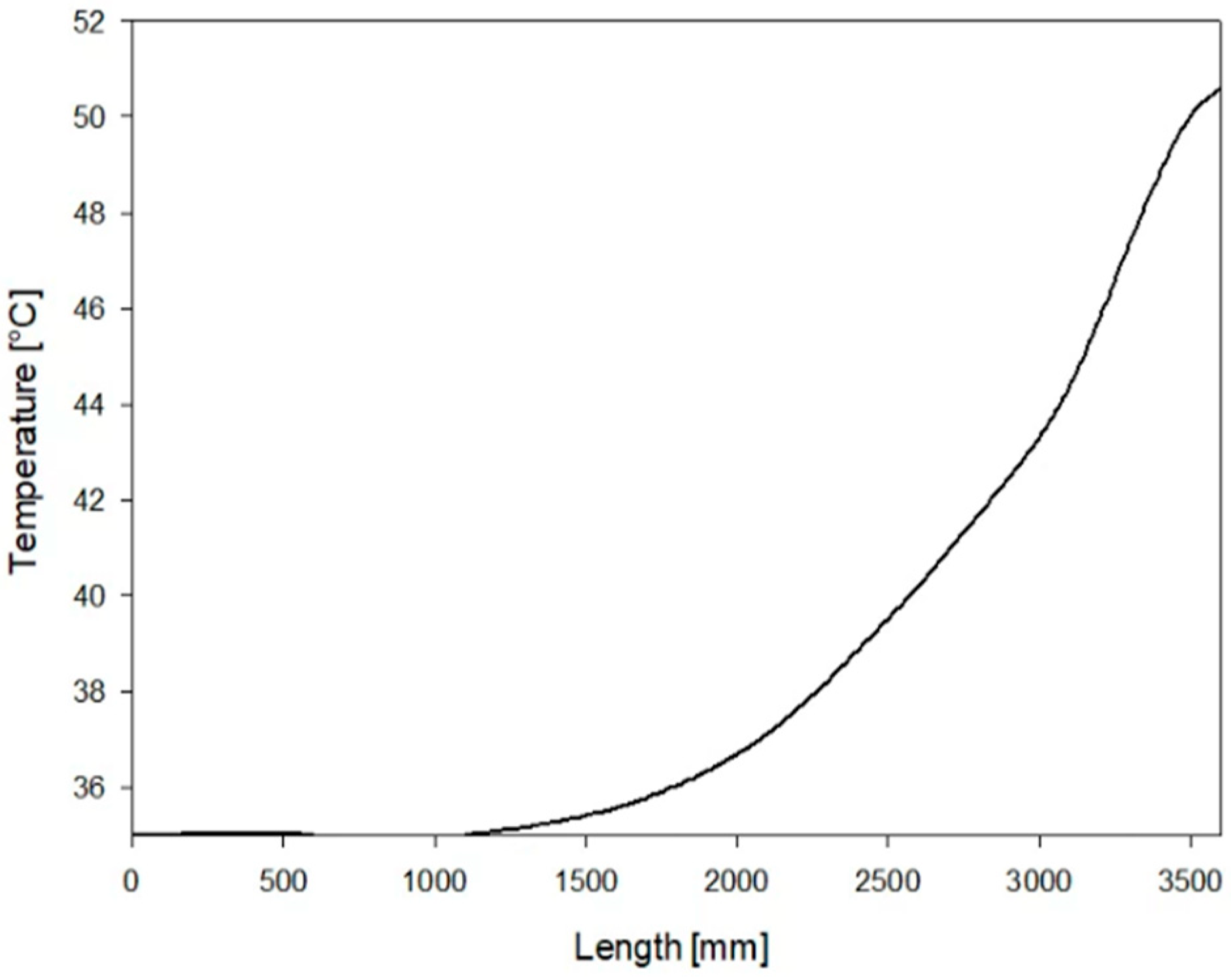
Based on the operating conditions in Table 2, steam had a flow rate of 90 kg/h, a pressure of 6 bar(g), an inlet temperature of 165 °C, and a glycol–water ratio of 50%. The heat exchanger operated in a parallel flow with a glycol–water flow rate of 6500 kg/h, a pressure range of 1.8–5 bar(g), and an inlet temperature of 35 °C. For the experimental obtained result, the outlet temperature of the heat exchanger was measured at 49.5 °C.
Figure 5 shows the numerical results for the temperature of the glycol–water in the heat exchanger with a pipe length in parallel flow, and Table 7 presents the experimental and numerical values of the glycol–water outlet temperature in the heat exchanger. The results showed that when the glycol–water flow rate was 6500 kg/h, pressure 2.4 bar(g), and inlet temperature 35 °C, outlet temperature of the glycol–water at the heat exchanger was maintained at 50.6 °C, showing that the error is about 2%. As a validation study, the numerical analysis method employed in this research was found to be reasonable and reliable, demonstrating good agreement with experimental results. While the little error between numerical and experimental results appears satisfactory, this validation is limited to specific operating conditions (glycol concentration of 50%, parallel-flow configuration). The agreement may not hold for extreme operating conditions or different system scales, requiring further validation studies

4.2. Parametric Study

In this section, the analysis is extended to include key operational and design parameters that govern the performance of double-pipe heat exchangers (DPHEs). Unlike previous studies that have primarily focused on single-fluid systems or isolated variables, the present work proposes a unified framework for multiparameter optimization in glycol–steam DPHEs. Specifically, this study investigates the impact of varying the glycol–water mixing ratio and compares parallel- versus counter-flow configurations, demonstrating that these parameters can lead to significant improvements in the overall heat transfer coefficient (UA) relative to conventional designs. Moreover, a practical validation procedure was implemented under field-relevant conditions—namely, steam flow at 90 kg/h, 6 bar(g), and 165 °C, and glycol–water flow at 6500 kg/h, 1.8–5 bar(g), and 35 °C—achieving agreement within ±2% of commissioning test data. This integrated approach not only enhances the theoretical understanding of DPHE behavior but also provides actionable design guidelines for improving thermal efficiency and operational reliability in LPG fuel supply systems.

4.2.1. Effects of the Turbulence Model

To examine the effect of the turbulence model, the k-ω and k-ε turbulence models were compared, as they are the most frequently used models for flow and heat transfer calculations in heat exchangers. Table 8 shows the outlet temperature of the glycol–water with turbulence models in the heat exchanger, where the numerical calculation was conducted with a mixing ratio of 50% of ethylene under the parallel-flow conditions.
The outlet temperature of the glycol–water mixture predicted by the k-ε turbulence model is closer to the experimental temperature of 49.5 °C compared to the k-ω turbulence model, showing that the k-ε turbulence model effectively predicts turbulent flows and the heat transfer such as large scale of heat exchanger. Especially, under parallel-flow conditions, where the fluid flows relatively uniformly, the k-ε turbulence model more predicts bulk flow characteristics effectively. In the k-ω turbulence model, near-wall effects and transitional flows were more accurately simulated. In the present calculation, wall effects are relatively less significant showing a less accurate prediction of 51.7 °C. In addition, with the high viscosity of glycol–water mixtures, convective heat transfer plays a more critical role than detailed near-wall flow structures. For the large-scale heat transfer, the k-ε turbulence model better accounts for heat transfer characteristics. These results demonstrate that the k-ε turbulence model is more suitable for large-scale flow conditions.
The effects of the turbulence model were also examined under different mixing ratios and flow direction conditions, as shown in Table 9. For the k-ε turbulence model, the outlet temperature gradually increased with the increasing glycol mixing ratio. By contrast, for the k-ω turbulence model, the outlet temperature showed fluctuating and unstable results depending on the mixing ratio due to the relative significance of wall effects.
These changes can be explained by the properties of the mixing ratio of ethylene glycol, as listed in Table 5. As the proportion of ethylene glycol increases with the mixing ratio, the thermal conductivity of the ethylene glycol–water mixture decreases. With an increasing ratio of ethylene glycol, an increase in viscosity can also result in a higher flow resistance and a potential reduction in the heat transfer coefficient. Owing to the high viscosity of ethylene glycol, exceeding 50% in the ethylene glycol–water mixing ratio can lead to flow-related drawbacks. Therefore, under these operating conditions, the ethylene glycol content was maintained at or below 50% to avoid such issues [35]. Therefore, for the aforementioned reasons, as the ethylene glycol content increased, the temperature rise decreased.
For the given flow conditions, it was observed that heat transfer is more effective in parallel flow compared to counter flow, regardless of the turbulence model applied. However, under counter-flow conditions, the differences between the k-ε and k-ω turbulence models became more pronounced, particularly at lower glycol–water mixing ratios. This suggests that the choice of turbulence model plays a more significant role in predicting heat transfer performance in counter flow and low mixing ratio conditions. In addition, the results showed that for the k-ε turbulence model, the outlet temperature gradually increased with the increasing glycol mixing ratio, indicating a more stable and consistent trend. In contrast, the k-ω turbulence model exhibited more fluctuating and unstable outlet temperature results depending on the mixing ratio, suggesting a higher sensitivity to changes in fluid properties.

4.2.2. Effect of the Glycol–Water Mixing Ratio and Flow Direction

Numerical analysis was performed by changing the ratio of ethylene glycol in each flow direction to 20%, 40%, and 60%. Table 10 shows the thermal conductance (UA) of ethylene glycol–water and the outlet temperature of the glycol–water with respect to the mixing ratio and flow direction. As the glycol ratio increases, the UA values tend to decrease in both parallel flow and counter flow. In addition, when the glycol increases from 20% to 40%, UA decreased by about 13.3% in parallel flow, and UA decreased by about 14% in counter flow. A similar decrease rate is shown when the increases thereafter. The UA values in parallel flow remain consistently higher than those in counter flow. This shows that parallel-flow conditions are better than counter flow in terms of heat transfer at the same glycol ratio. It also shows the smallest UA decrease rate in the high ratio section of 50% or more. This is due to the result of flow resistance due to increased viscosity.
Figure 6 shows the temperature with pipe length for glycol ratios of 20%, 40%, and 60% with parallel and counter flows. As the glycol ratio increased by 20%, the glycol–water outlet temperature increased by approximately 1%. When comparing the flow directions, it can be observed that the glycol–water outlet temperature was approximately 0.6% higher in the case of parallel flow than in counter flow. This suggests that heat transfer is more effective under parallel-flow conditions than under counter-flow conditions, resulting in a higher outlet temperature.
According to fundamental heat transfer theory, counter-flow heat exchangers typically exhibit superior performance compared to parallel-flow configurations due to enhanced log mean temperature difference (LMTD) values. However, the results presented in Table 10 reveal that the actual outlet temperature differences do not strictly adhere to this theoretical expectation. It is noteworthy that the outlet temperatures for parallel flow are marginally higher (by up to 0.6 °C) than those observed in counter flow across all tested mixing ratios, confirming that both configurations operate under comparable temperature driving forces in this specific application. Furthermore, the observed outlet temperature difference of 0.3 °C for the 50% mixing ratio falls well within the experimental and numerical uncertainty range of ±2%.
This relatively narrow temperature difference at the target outlet temperature of 49.5 °C can be attributed to several factors inherent to the system design and operating conditions. The moderate temperature span of the system, combined with the specific heat capacity characteristics of the glycol–water mixture, tends to minimize temperature profile variations between the two flow arrangements under these conditions. Additionally, the relatively short heat exchanger length and balanced flow rates further reduce the practical influence of flow direction on outlet temperature performance.
These findings demonstrate that while the heat transfer of counter-flow heat exchangers in maximizing thermal energy transfer is well established in classical heat transfer literature, the performance advantage can become negligible in practical engineering applications with constrained temperature ranges, as observed in the present study. The results underscore the importance of validating theoretical predictions against actual operational data for each specific design configuration and operating regime, particularly when making design decisions for real-world applications.
Figure 7 shows the change in the efficiency (ε) of the double-pipe heat exchanger according to the glycol–water mixing ratio (20%, 40%, 50%, and 60%). As shown in Figure 7, as the mixing ratio increases, the ε value steadily increases in both flow conditions, and especially from 50% or higher, the increase tends to become somewhat milder. When comparing parallel flow and counter flow, the ε of the parallel flow is about 0.5 to 1.0% higher in all sections, showing a slight advantage in the overall performance. This result seems to be due to the increase in the specific heat of the glycol–water mixture as the mixing ratio increases and the larger NTU value and temperature range.
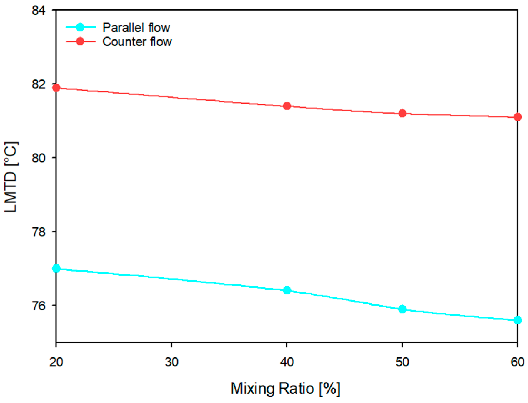
Figure 8 shows the change in the logarithmic mean temperature difference (LMTD) of the double-pipe heat exchanger according to the glycol–water mixing ratio (20%, 40%, 50%, and 60%) calculated using Equation (8). As shown in Figure 8, as the mixing ratio decreases, the LMTD value steadily decreases in both flow conditions, and especially from 50% or higher, the decrease tends to become somewhat milder. When comparing parallel flow and counter flow, the LMTD of the counter flow is about 6.4 to 7.3% higher in all sections, showing a slight advantage in the overall performance. This result seems to due to the temperature difference between the high-temperature fluid (steam) and the low-temperature fluid (glycol–water) decreases as the mixing ratio increases, resulting in a lower LMTD. This result can be used as a reference for heat exchanger design and mixture ratio optimization according to operating conditions. A similar study by Kolepaka and K. Bicha [36] compared the performance of parallel- and counter-flow heat exchangers using CFD. The study confirmed that counter flow has theoretically higher heat transfer efficiency and performs better under most operating conditions. However, similar to the results of this study, it is shown that parallel flow may be structurally advantageous or show relatively stable behavior in terms of outlet temperature control under certain inlet conditions or limited heat load conditions.

4.3. Application

4.3.1. The Effect of Geometry and Fluid Condition

In this section, the heat transfer phenomena in a DPHE used in an LPG fuel supply system are analyzed by evaluating various parameters, including the geometric characteristics, pipe material, and fluid conditions. The heat transfer conditions were established with high-temperature water (40 °C) flowing through the inner pipe while being exposed to an external liquid nitrogen environment (−196 °C). This setup facilitated a comprehensive evaluation of the heat exchange performance under varying operating conditions.
The pipe diameter is another crucial factor, as it directly affects the heat exchanger capacity and overall thermal performance. To evaluate the impact of geometric variations, the heat transfer characteristics were examined by altering key parameters, including the pipe material, diameter, and thickness. Furthermore, this study investigated the influence of fluid conditions such as flow rate and temperature, which significantly affect the heat transfer efficiency. The effects of these parameters were systematically analyzed to understand their roles in optimizing heat exchanger performance.
Figure 9 presents a schematic of the double-tube heat exchanger, and Table 11 summarizes the key specifications, including the pipe diameter—outer diameter (OD), wall thickness (WT), inner diameter (ID), and materials used (SUS and copper).
Figure 10 and Figure 11 illustrate the outlet temperature and overall heat transfer coefficient for SUS and copper pipes, respectively. Under identical operating conditions, the copper pipes exhibited lower outlet temperatures than the SUS pipes. Additionally, copper pipes have a smaller inner diameter and thickness in accordance with the standard specifications for heat exchanger piping, further enhancing their heat transfer efficiency. For instance, when liquid nitrogen was introduced at a mass flow rate of 0.00048 m3/s, the outlet temperature of the copper 20A pipe was the lowest at −101.2 °C. Conversely, for an SUS 50A pipe at a mass flow rate of 0.00097 m3/s, the outlet temperature reached the highest value of 28.5 °C. These findings emphasize the critical influence of pipe material, size, and flow rate on the overall performance of the heat exchanger.
Regarding the overall heat transfer coefficients, the copper 20A pipe exhibited the highest value of 12,066,497 W/m2·K at a mass flow rate of 0.00097 m3/s, while the SUS pipe demonstrated the lowest value of 268,620 W/m2·K at a mass flow rate of 0.00048 m3/s. These results indicate that optimal heat transfer efficiency is achieved at specific mass flow rates and pipe diameters within the inner pipe, emphasizing the importance of material selection and flow rate in enhancing heat exchanger performance. Furthermore, the findings indicate that heat transfer rates increase significantly at higher mass flow rates, showing an approximate increase of 8.9% to 81.7% as the mass flow rate increases. Additionally, a reduction in pipe diameter further enhanced heat transfer rates, with an increase of approximately 33.8% to 71.5%. These results underscore the critical role of both the flow rate and pipe dimensions in optimizing the performance of the heat exchanger, demonstrating that strategic modifications to these parameters can significantly improve thermal efficiency.
These results show that the strong nucleate boiling caused by the large temperature difference between liquid nitrogen and water, the increased surface area-to-volume ratio of the 20A small diameter pipe, and the high flow rate were caused. The overall heat transfer coefficient of the copper pipe was much higher than that of SUS. However, copper is weaker in corrosion resistance and contamination prevention than SUS, so regular maintenance is essential for cost-effective operation.

4.3.2. The Effect of Pipe Material

The selection of the pipe material plays a critical role in heat exchanger performance. Stainless steel (SUS) offers advantages, such as low-temperature stability, corrosion resistance, and minimal internal contamination, making it suitable for extreme environments. By contrast, copper piping provides superior thermal conductivity, corrosion resistance, and high tensile strength, making it widely applicable in heat exchanger designs that prioritize efficient heat transfer.
A sensitivity analysis was conducted to evaluate the influence of changes in material properties—specifically thermal conductivity, density, and specific heat—on the overall performance of the double-pipe heat exchanger (DPHE). The relative sensitivity coefficient was calculated using the following relation:
S X = U / U x / x
where S X is the relative sensitivity coefficient, U is the overall heat transfer coefficient, x is the material property, and Δ represents the change amount due to the change. This formulation is widely applied in environmental modeling, system analysis, and heat transfer studies. As noted by Lenhart et al. [37], the relative sensitivity of a variable x to a model output y can also be expressed as
I = y / y x / x
In this study, the governing equation was evaluated by introducing a ±10% variation in the thermal conductivity, density, and specific heat of copper and stainless steel (SUS), followed by calculating the corresponding change in the overall heat transfer coefficient U ( U / U ). Among the properties assessed, thermal conductivity exhibited the highest sensitivity. Copper, with a thermal conductivity approximately 23 times greater than that of SUS, significantly reduced conduction resistance. Although SUS has a specific heat about 1.3 times higher than that of copper, the impact of changes in density and specific heat on U was found to be negligible.
An increase in U leads to enhanced heat flux under a given thermal load, resulting in a reduction in the outlet temperature of the working fluid. This behavior is primarily attributed to copper’s superior thermal conductivity. Additionally, a smaller pipe diameter contributes to a higher surface-to-volume ratio, which slightly improves the convective heat transfer coefficient due to increased fluid turbulence.
The results of the sensitivity analysis revealed that the influence of material properties on U follows the order of thermal conductivity ≫ density ≫ specific heat. Therefore, optimizing double-pipe heat exchanger (DPHE) performance requires the selection of materials with high thermal conductivity and the use of pipes with smaller inner diameters. Based on the calculated values of the overall heat transfer coefficient, the optimal flow rate was identified as 0.00097 m3/s, while the least favorable condition corresponded to 0.00048 m3/s. These findings emphasize the importance of material selection and geometrical configuration in improving the thermal efficiency of DPHE systems.
Table 12 presents a technical comparison of DPHE performance characteristics with those of commercial heat exchangers. While the material and temperature specifications of the proposed model are generally comparable to those of commercial products, the DPHE developed in this study is specifically designed for marine applications and, therefore, does not support extreme pressure and temperature conditions to the same extent as units such as the Alfa Laval PCHE or the Kennedy Tank hairpin heat exchanger. However, the simplified structure of the proposed design is expected to reduce manufacturing costs by approximately 10–20% compared to commercial models. Furthermore, unlike the hairpin type, the straight-tube configuration of this model facilitates easier cleaning and inspection. In conclusion, although it does not match the high-pressure capabilities of commercial DPHEs used in petrochemical applications, the proposed model demonstrates both technological and economic competitiveness by targeting marine-specific requirements and reducing material usage and manufacturing complexity.

5. Concluding Remarks

This study investigates the heat transfer performance of a glycol–steam double-pipe heat exchanger (DPHE) within an LPG fuel supply system under varying operating conditions. A computational model and methodology were developed and validated by comparing the numerical results with experimental data obtained from commissioning tests. Additionally, the effects of turbulence models and parametric variations were evaluated by analyzing the glycol–water mixing ratio and flow direction—both of which are critical operational parameters for DPHE systems. Finally, the heat transfer behavior of the DPHE was further examined by considering the effects of geometric characteristics, pipe material, and fluid properties. The main conclusions are as follows:
  • A numerical validation analysis was performed to verify the reliability of the numerical methodology with the numerical parameters included steam 90 kg/h, 6 bar(g), and 165 °C, and the glycol–water (ethylene glycol 50%) used a flow rate of 6500 kg/h, a pressure of 1.8 to 5 bar(g), and an inlet temperature of 35 °C. The numerical results showed a deviation of ±2% from the experimental results under parallel-flow conditions, confirming that the numerical method employed is both reasonable and reliable, as it demonstrates good agreement with the experimental data.
  • In the comparison of temperature results using different turbulence models (k-ε and k-ω), both models produced nearly identical results under consistent conditions. Under the reference condition of 50% glycol and parallel flow, the k-ε turbulence model predicted a glycol–water outlet temperature of 50.6 °C, closely matching the experimental value. This indicates that the k-ε model more effectively predicts bulk flow characteristics and provides a better representation of heat transfer behavior.
  • Analysis of the effect of the mixing ratio of ethylene glycol (EG) to water on the heat transfer performance (UA value) revealed that changes in the glycol–water outlet temperature were directly correlated with variations in the UA value. As the glycol ratio increased by 20%, the UA value decreased by an average of 11% in parallel flow and 13% in counter flow. Additionally, the glycol–water outlet temperature was found to be approximately 0.6% higher in parallel flow compared to counter flow, suggesting slightly improved heat transfer performance in parallel-flow configurations under the same operating conditions.
  • The heat transfer performance of a double-pipe heat exchanger (DPHE) in an LPG fuel supply system was evaluated by examining geometry, pipe material, and fluid conditions. Copper pipes outperformed stainless steel, yielding lower outlet temperatures due to their higher thermal conductivity and more compact dimensions. These results underscore the critical importance of material selection and flow rate optimization, as both factors significantly influence heat exchanger effectiveness and overall thermal efficiency in of the heat exchanger applications.
  • This study offers significant contributions to the engineering design of double-pipe heat exchanger systems for LPG fuel supply applications. Future research should incorporate long-term operational variables to further improve the model’s applicability, thereby reinforcing its potential as a versatile and practical tool for the design and development of advanced fuel supply systems.

Author Contributions

Conceptualization, A.C.; Formal analysis, Y.K.; Investigation, S.L.; Data curation, Y.K. and A.C.; Writing—original draft, S.L.; Writing—review & editing, S.C.; Supervision, S.C. All authors have read and agreed to the published version of the manuscript.

Funding

This research received no external funding.

Data Availability Statement

Data is contained within the article.

Acknowledgments

This paper was conducted with the support by Korea Planning & Evaluation Institute of Industrial Technology with funding from 2024 Materials and Parts Technology Development Project (Ministry of Trade, Industry and Energy) (No.: RS-2024-00443505).

Conflicts of Interest

The authors declare no conflicts of interest.

Nomenclature

A Heat transfer area [ m 2 ] d Diameter of inner pipe [ m m ]
H Enthalpy [J] r i Radius of inner tube [mm]
h Heat transfer coefficient, [ W / ( m 2   K ) ] r o Radius of outer tube [mm]
R e Reynolds number (dimensionless) T h Temperature of hot fluid [ ]
p Pressure [bar] T c Temperature of cold fluid [ ]
Q Heat flux [ W / m 2 ] δ Thickness of heat transfer path inside and outside the surface [ m ]
T Temperature [ ] ε Energy dissipation rate [ m 2 / s 3 ]
U Overall heat transfer k Turbulence kinetic energy [ m 2 / s 2 ]
u Internal energy ρ Density [ k g / m 3 ]
T Logarithmic mean temperature [ ] τ Shear stress [ N / m 2 ]
W T Pipe thickness [ m ]
D Diameter of outer pipe [ m m ]

References

  1. Kim, B.-I.; Kim, K.-T.; Islam, S. Development of strength evaluation methodology for independent IMO type C tank with LH2 carriers. J. Ocean Eng. Technol. 2024, 38, 87–102. [Google Scholar] [CrossRef]
  2. DNV. Maritime Forecast to 2050: Energy Transition Outlook. 2023. Available online: https://www.dnv.com/publications/maritime-forecast-to-2050-edition-2023/ (accessed on 31 July 2025).
  3. Kim, S.-J.; Park, S.-J. Riser configuration design for a 15-MW floating offshore wind turbine integrated with a green hydrogen facility. J. Ocean Eng. Technol. 2024, 38, 137–147. [Google Scholar] [CrossRef]
  4. Nam, T.; Yu, T.; Lim, Y. Thermodynamic modeling and analysis of boil-off gas generation and self-pressurization in liquefied carbon dioxide tanks. J. Ocean Eng. Technol. 2024, 38, 257–268. [Google Scholar] [CrossRef]
  5. Lee, H.-Y. A Study on the Rule and Design of the LPG Hybrid Electric Propulsion System for Small Vessels, Korea Maritime and Ocean University. 2023. Available online: http://repository.kmou.ac.kr/handle/2014.oak/13205 (accessed on 31 July 2025).
  6. Lee, S.-W.; Jeong, S.-Y.; Choi, S.-W. Frost behavior in ambient air vaporizer. J. Korean Soc. Mar. Eng. 2021, 45, 17–20. [Google Scholar] [CrossRef]
  7. Kang, D.-H. A Study on the Commercialization Possibility of LPG Engines for Medium-Sized Vessels in South Korea, Korea Maritime and Ocean University. 2023. Available online: http://kmou.dcollection.net/common/orgview/200000670640 (accessed on 31 July 2025).
  8. Heo, J.-W.; Choi, Y.-H.; Kim, S.-H.; Lee, S.-H.; Choi, H.-Y.; Yoo, D.-I.; Lee, Y.-W. Predicting heat transfer performance in a complex heat exchanger for LNG FGSS development. J. Korean Soc. Mar. Eng. 2023, 47, 52–58. [Google Scholar] [CrossRef]
  9. Han, S.H.; Kim, H.S.; Han, B.U.; Lee, D.J. A study on the fuel supply system of LPG propulsion VLGC ME-LGIP engine. Bull. Soc. Na-Val Archit. Korea 2019, 56, 10–14. [Google Scholar]
  10. Choi, A.; Lee, S.; Shin, I.H.; Choi, S. Study on simulation of cooling water through concentric double pipe heat exchanger. Trans. Korean Hydrog. New Energy Soc. 2023, 34, 741–747. [Google Scholar] [CrossRef]
  11. Park, C.; Kwon, H.; Ali, E.; Seo, J.; Lee, B.; Kim, I.; Kim, S.; Park, H. Numerical analysis study on the flow properties of shell-tube heat exchanger with different baffle angle. J. Comput. fluids Eng. 2023, 28, 80–87. [Google Scholar] [CrossRef]
  12. Mai, V.T.; Mai, T.L.; Yoon, H.K. Numerical Investigation of Motion Response of the Tanker at Varying Vertical Center of Gravities. J. Ocean Eng. Technol. 2024, 38, 1–9. [Google Scholar] [CrossRef]
  13. Kim, J.-B.; Min, E.-H.; Koo, W. Experimental and numerical study on the characteristics of free surface waves by the movement of a circular cylinder-shaped submerged body in a single fluid layer. J. Ocean Eng. Technol. 2023, 37, 89–98. [Google Scholar] [CrossRef]
  14. Lee, S.-W.; Choi, S.-W. Fin and temperature effect of frost in ambient air vaporizer. J. Ocean Eng. Technol. 2022, 36, 211–216. [Google Scholar] [CrossRef]
  15. Mozley, J.M. Predicting dynamics of concentric pipe heat exchangers. Ind. Eng. Chem. 1956, 48, 1035–1041. [Google Scholar] [CrossRef]
  16. Cohen, W.C.; Johnson, E.F. Dynamic characteristics of double-pipe heat exchangers. Ind. Eng. Chem. 1956, 48, 1031–1034. [Google Scholar] [CrossRef]
  17. Aicher, T.; Kim, W. Experimental investigation of the influence of the cross flow in the nozzle region on the shell-side heat transfer in double-pipe heat exchangers. Int. Commun. Heat Mass Transf. 1998, 25, 43–58. [Google Scholar] [CrossRef]
  18. Dezfoli, A.R.A.; Mehrabian, M.A. The overall heat transfer characteristics of a double-pipe heat exchanger. Heat Transf. Res. 2009, 40, 555–570. [Google Scholar] [CrossRef]
  19. Moradi, M.; Etemad, S.G.; Moheb, A. Laminar flow heat transfer of a pseudoplastic fluid through a double pipe heat ex-changer. Iran. J. Chem. Eng. 2006, 3, 13–19. [Google Scholar]
  20. Naphon, P. Heat transfer and pressure drop in the horizontal double pipes with and without twisted tape insert. Int. Commun. Heat Mass Transf. 2006, 33, 166–175. [Google Scholar] [CrossRef]
  21. Choudhari, S.S.; Taji, S. Experimental studies on effect of coil wire insert on heat transfer enhancement and friction factor of double pipe heat exchanger. Int. J. Comput. Eng. Res. 2013, 3, 32–39. [Google Scholar]
  22. Zhang, L.; Guo, H.; Wu, J.; Du, W. Compound heat transfer enhancement for shell side of double-pipe heat exchanger by helical fins and vortex generators. Heat Mass Transf. 2012, 48, 1113–1124. [Google Scholar] [CrossRef]
  23. Braga, C.; Saboya, F. Turbulent heat transfer, pressure drop and fin efficiency in annular regions with continuous longitudinal rectangular fins. Exp. Therm. Fluid Sci. 1999, 20, 55–65. [Google Scholar] [CrossRef]
  24. Zamzamian, A.; Oskouie, S.N.; Doosthoseini, A.; Joneidi, A.; Pazouki, M. Experimental investigation of forced convective heat transfer coefficient in nanofluids of Al2O3/EG and CuO/EG in a double pipe and plate heat exchangers under turbulent flow. Exp. Therm. Fluid Sci. 2011, 35, 495–502. [Google Scholar] [CrossRef]
  25. Prasad, P.D.; Gupta, A.; Deepak, K. Investigation of trapezoidal-cut twisted tape insert in a double pipe u-tube heat exchanger using Al2O3/water nanofluid. Procedia Mater. Sci. 2015, 10, 50–63. [Google Scholar] [CrossRef]
  26. Han, K.-Y.; Lim, H.-G.; Lee, J.-W. Performance analysis of a constant-speed LPG engine. J. Adv. Mar. Eng. Technol. (JAMET) 2024, 48, 63–71. [Google Scholar] [CrossRef]
  27. Marzouk, S.; Almehmadi, F.A.; Aljabr, A.; Alam, T.; Singh, T.; Khargotra, R. Effects of extended pin fins on the hydrothermal performance of double pipe heat exchanger. Therm. Sci. Eng. Prog. 2024, 55, 102915. [Google Scholar] [CrossRef]
  28. Alkalibi, A.; Alahmadi, Y.H.; Tlili, I. Performance Analysis of an Extended-Surface Double-Pipe Heat Exchanger for Heat Recovery from Hot Exhaust Gas Using Water and Nanofluids. Results Eng. 2025, 27, 106140. [Google Scholar] [CrossRef]
  29. Kavitha, R.; Algani, Y.M.A.; Kulkarni, K.; Gupta, M. Heat transfer enhancement in a double pipe heat exchanger with copper oxide nanofluid: An experimental study. Mater. Today: Proc. 2022, 56, 3446–3449. [Google Scholar] [CrossRef]
  30. Venkatesh, B.; Khan, M.; Alabduallah, B.; Kiran, A.; Babu, J.C.; Bhargavi, B.; Alhayan, F. Design Optimization of Counter-Flow Double-Pipe Heat Exchanger Using Hybrid Optimization Algorithm. Processes 2023, 11, 1674. [Google Scholar] [CrossRef]
  31. Esfandyari, M.; Delouei, A.A.; Jalai, A. Optimization of ultrasonic-excited double-pipe heat exchanger with machine learning and PSO. Int. Commun. Heat Mass Transf. 2023, 147, 106985. [Google Scholar] [CrossRef]
  32. Gabir, M.M.; Albayati, I.M.; Hatami, M.; Alkhafaji, D. An experimental investigation of the convective heat transfer augmentation in U-bend double pipe heat exchanger using water-MgO-Cmc fluid. Sci. Rep. 2024, 14, 1–13. [Google Scholar] [CrossRef]
  33. Jeong, J.-Y.; Nam, S.-C.; Kang, Y.-T. A Numerical analysis on the heat transfer and pressure drop characteristics of welding type plate heat exchangers. J. Adv. Mar. Eng. Technol. 2008, 32, 676–682. [Google Scholar] [CrossRef]
  34. Versteeg, H.K.; Malalasekera, W. An introduction to computational fluid dynamics: The finite volume method; Longman Scientific & Technical Publisher: Harlow, UK, 1995. [Google Scholar]
  35. Gemicioğlu, B.; DemirCan, T. Experimental analysis of the effects of using different water-ethylene glycol mixture rates on heat transfer performance in a heat exchanger. J. Eng. Archit. Fac. Eskiseh. Osman. Univ. 2021, 29, 145–157. [Google Scholar] [CrossRef]
  36. Sridhar, K.; Bicha, K. Comparative analysis of parallel and counter flow heat exchangers. Sci. Eng. Technol. Res. 2017, 6, 0638–0644. [Google Scholar]
  37. Lenhart, T.; Eckhardt, K.; Fohrer, N.; Frede, H.-G. Comparison of two different approaches of sensitivity analysis. Phys. Chem. Earth Parts A/B/C 2002, 27, 645–654. [Google Scholar] [CrossRef]
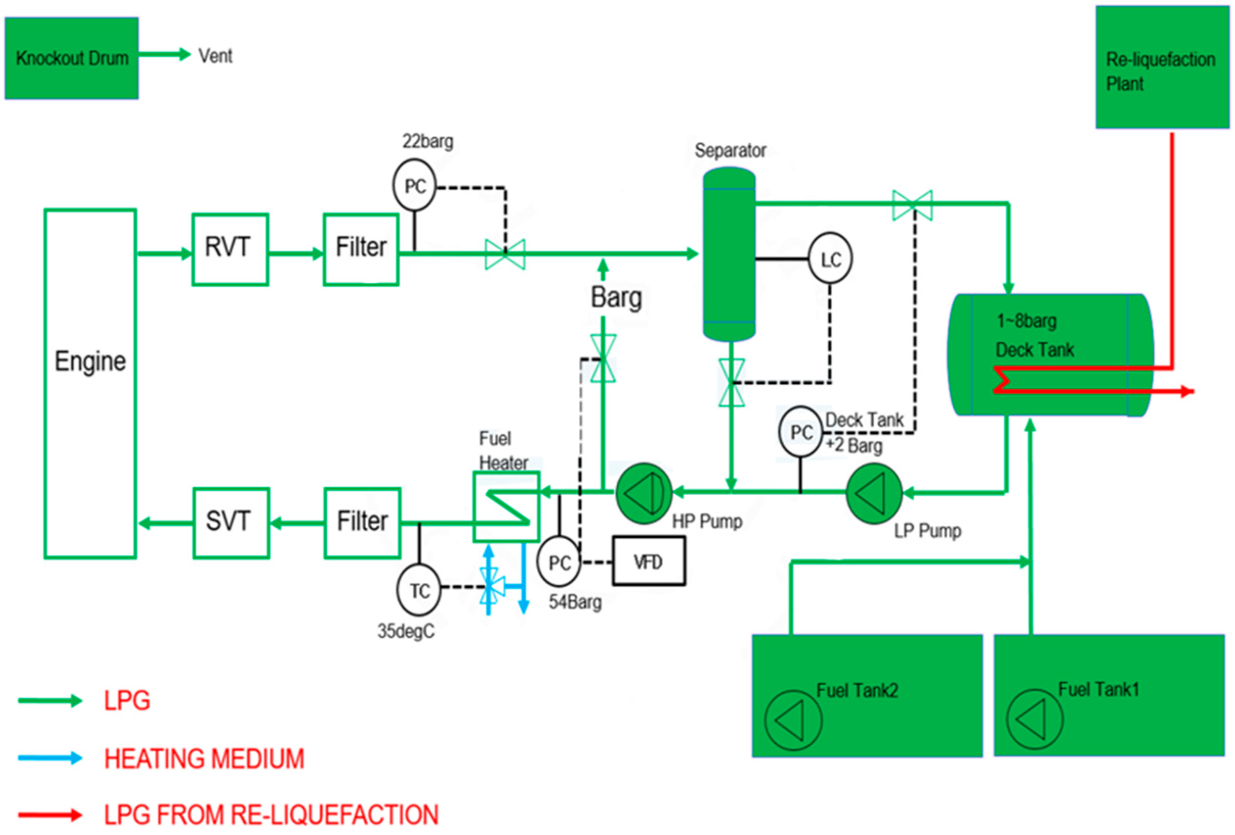
Figure 1. LPG fuel supply system.
Energies 18 04179 g001
Figure 2. Glycol–water heating system.
Energies 18 04179 g002
Figure 3. Sectional view of double-pipe heat exchanger.
Energies 18 04179 g003
Figure 4. Numerical model of double-pipe heat exchanger.
Energies 18 04179 g004
Figure 5. Temperature of glycol–water in the heat exchanger with pipe length.
Energies 18 04179 g005
Figure 6. Temperature with pipe length by glycol ratio 20%, 40%, 60%, steam for the (left): parallel flow and (right): counter flow.
Energies 18 04179 g006
Figure 7. Effectiveness with mixing ratio by glycol ratio 20%, 40%, 50%, 60%, for the parallel flow and counter flow.
Energies 18 04179 g007
Figure 8. LMTD with mixing ratio by glycol ratio 20%, 40%, 50%, 60%, for the parallel flow and counter flow.
Energies 18 04179 g008
Figure 9. Schematic of double-pipe heat exchanger.
Energies 18 04179 g009
Figure 10. Outlet temperature in case of pipe ((left): SUS, (right): COPPER).
Energies 18 04179 g010
Figure 11. Overall heat transfer coefficient in case of pipe ((left): SUS, (right): Copper).
Energies 18 04179 g011
Table 1. Comparison of LPG and LNG characteristics.
PropertyLPGLNGUnit
Liquefaction Temperature
(at atmospheric pressure)
−42−162°C
Boiling Point−42−162°C
Density (liquid)500–580430–470 k g / m 3
Density (gas, 15 °C)1.8980.66 k g / m 3
Liquid Volume Ratio1/2501/600-
Storage conditions
Storage Pressure (at 20 °C)7Atmosphericbar
Storage Pressure (at 45 °C)18Atmosphericbar
Storage Temperature Range−42 to 45−162 to −157°C
Environmental Impact
C O 2 Reduction (vs. HFO)15–2020–25%
S O x Reduction (vs. HFO)90–9595–100%
N O x Reduction (vs. HFO)10–2080–90%
Table 2. Condition of glycol–steam double-pipe heat exchanger.
Inner Pipe
(Glycol–Water)
Outer Pipe
(Steam)
DN (A)80125
Pressure (bar)1.8~56
In ( )35165
Out ( )49.590
Required
Flow Rate ( k g / h )
650090
Setting Temperature ( K )3540
Table 3. Geometric condition of glycol–steam double-pipe heat exchanger.
DimensionDescription
Reynolds number, (Re)7200–20,000
Inner pipe wall thickness [mm]5.5
Outer pipe wall thickness [mm]6.6
Inner pipe diameter [mm]78.1
Outer pipe diameter [mm]139.8
Total length [mm]3600
Table 4. Physical characteristics glycol–water and steam.
Fluids PropertiesEthylene Glycol (50%) + Fresh Water (50%)Steam
Density ( k g / m 3 )10440.4981
Thermal conductivity ( W / m K )0.3930.0302
Temperature inlet ( )35165
Temperature outlet ( )49.590
Viscosity ( m m 2 / s )2.9871.479 × 10−5
Mass flow rate ( k g / s )1.8050.025
Specific heat transfer capacity ( K J / k g K )3.6901.977
Table 5. Physical characteristics according to mixing ratio of ethylene glycol and fresh water.
Mixing ratio (%)Ethylene glycol20405060
Fresh water80605040
Density ( k g / m 3 )1022103310441069
Specific heat ( K J / k g K )43.823.823.56
Thermal conductivity ( W / m K )0.4910.4330.3990.354
Viscosity ( m m 2 / s )1.422.262.983.73
Table 6. Mesh independence study.
Case. NoTotal Number of NodesTotal Number of ElementDifferences Value of for Outlet Temperature (%)
1101,040328,7322.44
2192,272486,5430.49
3260,158622,1030.10
4342,018782,733Under 0.01
Table 7. Comparison of the outlet temperature of the glycol–water between experiment and numerical value.
Mixing ratio (%)Ethylene glycol50
Fresh water50
Flow rate ( k g / h )6500
Experimental result ( )49.5
Numerical result ( )50.6
Error (%)2
Table 8. The outlet temperature of the glycol–water with turbulence models.
Parallel flowMixing ratio (%)Ethylene glycol50
Fresh water50
Glycol–water inlet temperature ( )35
k-ε modelGlycol–water outlet temperature ( )51.7
k-ε modelGlycol–water outlet temperature ( )50.6
Table 9. The outlet temperature of the glycol–water (GW) with flow conditions and mixing ratio under turbulence models.
Parallel Flow
Mixing Ratio (%)GW Inlet (°C)k-ω Modelk-ε Model
Ethylene GlycolFresh WaterGW Outlet (°C)GW Outlet (°C)
20803550.049.1
406050.950.0
505051.750.6
604049.851.0
Counter Flow
Mixing ratio (%)GW Inlet (°C)k-ωmodelk-εModel
Ethylene glycolFresh waterGW Outlet (°C)GW Outlet (°C)
20803550.048.7
406051.149.8
505051.250.3
604049.250.6
Table 10. Heat transfer characteristics outlet temperature of the glycol–water (GW) with flow conditions and mixing ratio under turbulence models.
Parallel Flow
Mixing Ratio (%)UA (kw/°C)GW Inlet (°C)GW Outlet (°C)Steam Inlet
(°C)
Steam Outlet
(°C)
Ethylene GlycolFresh Water
20801.37863549.116590
40601.195250.0
50501.231850.6
60401.270151.0
Counter Flow
Mixing ratio (%)UA (kW/°C)GW Inlet (°C)GW Outlet (°C)Steam Inlet
(°C)
Steam Outlet
(°C)
Ethylene glycolFresh water
20801.34953548.716590
40601.160149.8
50501.213650.3
60401.235950.6
Table 11. Specifications of pipe material (SUS, copper).
MaterialSUS 304 KS D 3576
DN
(A)
2025324050
OD
( m m )
27.234.042.748.660.5
WT
( m m )
1.651.651.651.651.65
ID
( m m )
23.930.739.445.357.2
Material“L” TYPE KS D 5301
DN
(A)
2025324050
OD
( m m )
22.228.534.941.253.9
WT
( m m )
1.141.271.401.521.78
ID
( m m )
19.926.032.138.250.4
Table 12. Technical comparison of DPHE performance characteristics with commercial heat exchangers.
ParameterPresent Study DPHEKennedy Tank Hairpin DPHEAlfa Laval DPHE
ConfigurationSingle inner pipe + outer pipe compact designU-shaped hairpin, single inner/outer pipeStraight concentric tube configuration
Flow arrangement Parallel/Counter Counter Counter
MaterialCopper (Cu)/SUSSS304, SS316LCopper alloy, SS316L
Design standardsCustom (marine LPG application)ASME VIII, TEMA, API 650ASME BPE (hygienic), ASME VIII upon request
Design temperature range−200~300 °C−50~450 °C−253~800 °C
Maintenance requirementsMedium (regular cleaning and inspection required)Low (simple structure)Low (modular design)
Disclaimer/Publisher’s Note: The statements, opinions and data contained in all publications are solely those of the individual author(s) and contributor(s) and not of MDPI and/or the editor(s). MDPI and/or the editor(s) disclaim responsibility for any injury to people or property resulting from any ideas, methods, instructions or products referred to in the content.