Article

Cross-Scale Simulation Study of Porous Medium Heat Exchangers Based on Reliable Cell Selection

by
Yiqiang Liang
1,2,
Jun Zhang
1,
Yu Liu
1,*,
Mingrui Sun
1 and
Yongchen Song
1,*
1
Key Laboratory of Ocean Energy Utilization and Energy Conservation of Ministry of Education, Dalian University of Technology, Dalian 116024, China
2
AECC Shenyang Aeroengine Research Institute, Shenyang 110015, China
*
Authors to whom correspondence should be addressed.
Energies 2025, 18(13), 3510; https://doi.org/10.3390/en18133510
Submission received: 8 June 2025 / Revised: 29 June 2025 / Accepted: 1 July 2025 / Published: 3 July 2025
(This article belongs to the Collection Advances in Heat Transfer Enhancement)

Abstract

This study compares the heat transfer and pressure drop of three cell structures, namely Kelvin cells (KCs), ellipsoidal Kelvin cells (EKCs), and body-centered cubic (BCC) structures, at the cell scale in order to identify the superior configuration. Then, we conducted numerical simulations on the heat exchangers based on porous media, and evaluate their comprehensive performance. It is shown that KCs have a superior heat transfer. Their volumetric heat transfer coefficient (hV) is more than 50% higher than that of EKCs and more than 100% higher than that of BCC structures. EKCs exhibit a lower pressure drop. In the heat exchanger performance optimization study, the Kelvin structure demonstrated significant heat transfer characteristics. Simulation data show that the heat transfer performance at the hot end of the Kelvin heat exchanger (KCHE) is enhanced by more than 40% compared to the conventional plate-fin structure (FHE), but its flow channel pressure drop characteristics show a significant nonlinear increase. It is noteworthy that the improved Kelvin heat exchanger (EKCHE), optimized by introducing elliptic cell topology, maintains heat transfer while keeping the pressure loss increase within 1.22 times that of the conventional structure. The evaluation of the heat transfer and pressure drop characteristics is consistent for both scales. In addition, the EKC configuration exhibits a superior overall heat transfer capacity. To summarize, this work proposes a systematic numerical framework encompassing cell unit screening through heat exchanger design, offering valuable guidance for the structured development and analysis of porous media heat exchangers in relevant engineering domains.

1. Introduction

Porous media have attracted extensive attention in the field of engineering due to their unique structural characteristics. These materials possess large specific surface areas [1], where their microstructure enhances heat transfer efficiency through continuous ligaments and a high surface area density, while the porosity characteristics influence fluid permeability and cell-scale thermofluidic interactions [2]. Secondly, in terms of mechanical properties, the porous medium exhibits excellent specific strength characteristics, combined with its unique energy dissipation mechanism [3,4]. This makes it an ideal material for energy absorption. Based on the above properties, porous media have been widely used in the field of thermal engineering [5]. Of particular interest is the fact that that in the aerospace field, the comprehensive performance advantages of porous media are effectively utilized through precision-designed compact heat exchangers, fully demonstrating the value of this material for engineering applications under extreme working conditions [6,7].
As a key material for enhanced heat transfer, porous media show unique advantages in heat exchanger design. Studies have shown that such structures can significantly improve the overall heat transfer efficiency of heat exchanger systems [8]. Vishkaei’s team has demonstrated, through experimental modeling of a double-tube heat exchanger, that the porous ring structure of the metal foam leads to a significant increase in the average heat transfer coefficient [9]. To address the pressure drop of the porous media, T’Joen’s team optimized the geometrical topology of the open cell foam to achieve a low pressure loss on the air side. When the porous medium is fully thermally coupled to the tube wall, its compact structure exceeds the performance of conventional spiral-finned tubes at high flow rates [10]. Zaib et al.’s study based on plate heat transfer configurations further reveals that combining porous media and fin structures with thermal interface materials (TIMs) can synergistically increase the heat transfer area and improve energy efficiency conversion levels [11]. However, the application of porous structures increases the complexity of heat exchangers, posing significant challenges for full-scale numerical simulation studies [12]. Consequently, researchers have increasingly adopted porous media models to investigate heat exchangers. Wang et al. [12] employed a porous media model to analyze the hydrodynamic performance of full-scale plate-fin heat exchangers. Haider et al. [13] utilized a porous media approach to examine the effects of inlet configuration and distributor geometry on the efficiency and pressure drop in cryogenic plate-fin heat exchangers. Chung et al. [14] applied conjugate heat transfer with an improved porous media method to assess the impact of flow distribution on thermal–hydraulic performance.
Furthermore, at the cell scale, with the development of 3D printing technology, research into different lattice structures has become a trend [15,16]. Ho, JY et al. designed a novel porous insert with Rhombi Octet cell design, which is able to effectively enhance the heat transfer and hydraulic performance of cylindrical runner water-cooled plates compared to empty runner and spiral inserts [17]. Baishya, MJ et al. proposed a novel simple cuboctahedral (SCO) lattice, which exhibits better mechanical properties and can realize lightweight applications in conjunction with fabrication using 3D printing technology [18]. At the heat exchanger scale, Dhavale et al. [19] treated metal foam as a porous media and conducted a parametric analysis of partially filled high-porosity metal foam in double-pipe heat exchangers. Ashreet et al. [20] investigated the flow and heat transfer characteristics of porous structures in heat exchangers using a pore-scale model based on the lattice Boltzmann method (LBM). However, the complex random structure of most metal foams imposes greater limitations on pressure drop and reliability in stochastic porous media heat exchangers. Consequently, researchers have shown growing interest in ordered regular porous structures including KCs, BCC structures, and so on, which exhibit better heat transfer characteristics and strength properties. In recent years, people have gradually been focusing on the study of special porous structures, including Kelvin cells (KCs), body-centered cubic cells (BCCs), and so on. They have better heat transfer characteristics and strength properties. Buonomo, B et al. studied the pressure drop and heat transfer characteristics of KCs at the microscopic scale and at different numbers of cells per inch (CPI) [21]. Calati, M et al. discussed the effect of the macroscopic geometry of KCs on the thermal and hydraulic behavior in the forced convection of air [22]. Further, Iasiella, M et al. found that the heat transfer and pressure drop properties of KCs are affected by anisotropy, stretching along the flow direction effectively reduces the pressure drop, and the heat transfer is slightly reduced [23]. Sun, MR et al. [24] also pointed out that the ellipsoidal Kelvin cells (EKCs) exhibit a better performance than the original KCs in terms of the integrated overall heat transfer capacity after stretching along the flow direction. In addition, they further investigated the effect of stretching length on heat transfer and concluded that the performance is better when the ratio of the long and short axes is 2 [25]. Shi, XH et al. [26] investigated the heat transfer characteristics of compact heat exchangers with several structures and concluded that BCCs can effectively improve the heat transfer efficiency of the heat exchanger. Corbett et al. [27] noted that BCCs outperform the Kagome structure in heat transfer efficiency. However, systematic comparative studies on KCs, BCCs, and similar structures at reduced scales remain relatively scarce. Numerical simulation research on heat exchangers incorporating such ordered porous structures using porous media models is also quite limited.
Therefore, this study systematically compares the heat transfer and pressure drop characteristics of KCs, EKCs, and BCC structures. These findings are then combined with a porous media model to design porous media heat exchangers, with their comprehensive performance being evaluated. This approach provides insights into the systematic design and application of porous media heat exchangers in relevant fields. The heat exchanger is expected to be used in aerospace and other scenarios where a high degree of compactness for the heat exchanger, as well as lightweight applications, is required.

2. Experimentation and Simulation

2.1. Model

2.1.1. The Cell Unit Model

Figure 1 illustrates the morphological characteristics of the KCs, EKCs, and BCC cells, all of which are cylindrical pillars. The EKCs are elongated in the flow direction (x-direction) with a short-to-long axis ratio of 2 compared to KCs. Their porosities and structural parameters are detailed in Table 1, with their shapes being regular; their volumes are constrained as shown in Equation (1).
V = b × a 2
Here, a indicates the cell length in the y-direction relative to the z-direction, while b represents the length in the x-direction (flow direction). They were designed based on the channel height [28] specifications of compact plate-fin heat exchangers, while porosity φ was constrained by manufacturing feasibility and fluid flow requirements [29], and is defined as the ratio of the volume of holes to the overall volume. The rod diameter is ds. The specific surface area SV is defined as shown in Equation (2), and SH is the surface area of a single cell.
S V = S H V
d h = 4 φ S V
The hydraulic diameter [30] dh of the porous medium is defined as shown in Equation (3), with φ representing the porosity of the cell. As documented in published studies, the minimum manufacturable feature size for metal 3D printing is 0.4 mm [29]. In our porous structures, the minimal rod diameter reaches 0.417 mm, exceeding this threshold. Consequently, all cell units are compatible with 3D printing, demonstrating industrial feasibility.

2.1.2. Heat Exchangers

In this study, a conventional plate-fin heat exchanger (FHE) is used as a baseline model to construct the heat exchanger core with dimensions of 250 × 200 × 30 mm3. A five-layer alternating hot and cold runner stack design is adopted, with a single-layer runner height of 2.5 mm. Symmetric fin topology configuration is used for the internal runners. Figure 2 illustrates the heat transfer elements within the runners. The cold-side runner utilizes standard straight-through fins, while the hot-side runner incorporates serrated fins [31]. In porous media heat exchangers, such as the KC, EKC, and BCC configurations, serrated fins are replaced by specific designs, as depicted in Figure 2. Notably, Sun et al. [25] emphasize that the long axis of EKCs should align with the flow direction to minimize the pressure drop, whereas the arrangement of KCs and BCC cells is less critical. The fins or cells are oriented along the flow path.

2.2. Numerical Simulation

2.2.1. Physical Modeling and Boundary Conditions

For an in-depth investigation of the heat transfer and flow characteristics of porous cells, a multi-scale research framework is constructed in this study. Through the design of the characteristic cell model, the hydrodynamic fully developed section is specially set up to effectively eliminate the interference of the inlet effect on the test results. The geometrical parameters of the benchmark cell model are derived theoretically, and its topological configuration is based on a feature size system, whereby the flow direction feature scale, lateral feature scale, and normal feature scale maintain a specific ratio relationship, which ensures the controllability of the flow evolution process and the universality of the test data. The KCs and BCC cells are arranged in two rows and six columns, while the EKCs are configured in two rows and three columns. Figure 3a illustrates the flow state and boundary conditions for the BCC cell unit model.
The inlet and outlet conditions were defined as a velocity inlet and pressure outlet, respectively, with sufficiently long ends to ensure complete fluid development. The inlet velocity varied from 10 m/s to 80 m/s in 10 m/s increments, resulting in eight distinct working conditions for each structure. The bottom wall served as a heating surface with a heat flux of 13,000 W/m2, while the left and right walls were symmetric, the upper wall was no-slip, and the remaining walls were adiabatic [32].
Meshing was conducted using ICEM, with the local details illustrated in Figure 3b. The mesh is refined in the skeleton and heating surface to enhance calculation accuracy, employing a self-generated unstructured tetrahedral mesh for the simulations.
A grid sensitivity analysis was conducted on the KC structure at 20 m/s flow velocity. The temperature difference (ΔT) between the heated wall and the fluid, along with the pressure drop (ΔP), served as the convergence criteria. As summarized in Table 2, when the mesh count increased to the level of Case 3, the relative errors in ΔT and ΔP compared to the finest grid (Case 4) were both below 2%, confirming the computational reliability of Case 3. Grid-independence was verified for the rest of the structures. Consequently, the final simulations employed approximately 5.84 million, 5.52 million, and 5.26 million cells for the KC, EKC, and BCC structures, respectively.
Heat transfer simulations of the complete heat exchanger were conducted using FloEFD 12.0. The software employs a Cartesian coordinate system with an unstructured adaptive hexahedral mesh for discretization, facilitating flow and heat transfer analysis [33]. The mesh level is set to 7, indicating a finer mesh resolution, as shown in Figure 4.
Aero-engine heat exchangers endure harsh conditions where bypass air temperature/pressure vary with flight altitude and Mach number, while specific structural constraints must be considered [34]. Therefore, based on the actual operating conditions of aerospace porous-media heat exchangers, the designed mass flow rate, total pressure, and inlet temperature [34] are summarized in Table 3. Additionally, pressure-inlet and mass-flow-outlet boundary conditions were applied to ensure physical consistency. m l , h o t is the hot-side flow rate, m l , c o l d is the cold-side flow rate, P h o t is the hot-side pressure, P c o l d is the cold-side pressure, T h o t , i n is the inlet temperature of the hot side, and T c o l d , i n is the inlet temperature of the cold side.

2.2.2. Governing Equations

In this study, heat flow transfer simulations were conducted for three porous media cell unit models using ANSYS Fluent 22.0. A pressure-based solver was employed, assuming an incompressible fluid flow in a steady state. The Coupled algorithm was utilized to solve the momentum and pressure correction equations, with the relaxation factor initially set to default and adjusted as needed for convergence. According to Dukhan et al. [35], turbulence in porous media occurs at a Re of approximately 50; the lowest Re for the porous media in this study was 1069.3, significantly exceeding this threshold. The SST k-ω turbulence model was implemented, with control equations [24,33] widely referenced in the literature, which requires a y+ value of less than 1. Additionally, a residual convergence accuracy of 10−8 was established to ensure the complete convergence of the target parameters.
Furthermore, ANSYS Fluent 22.0 was employed for flow and heat transfer simulations. We assumed an incompressible steady-state flow with constant material properties. The governing equations are based on the steady-state Navier–Stokes equations [36]. The specific governing equations and turbulence model are as follows:
Continuity Equation:
x i ( ρ u i ) = 0
Momentum Equation:
x i ( ρ u i u j ) = p x i + x j μ u i x j
Energy Equation:
x i ( ρ u i c p T ) = x i λ T x i
where ρ denotes density, p represents pressure, u indicates flow velocity, and T signifies thermodynamic temperature. μ denotes dynamic viscosity, μt refers to turbulent viscosity, cp refers to specific heat capacity at constant pressure, and λ refers to thermal conductivity.
The k-ε turbulence equation is as follows:
( ρ k ) t + x j ρ u j k x j μ + μ t σ k k x j = μ t u i x j u i x j + u j x i ρ ε
( ρ ε ) t + x j ρ u j ε μ + μ t σ ε ε x j = c ε 1 ε k μ t u i x j u i x j + u j x i c ε 2 ρ ε 2 k
μ t = ρ c μ k 2 ε
where k denotes turbulent kinetic energy, ε represents dissipation rate, and t denotes time. Additionally, cμ is assigned a constant value of 0.09, cε1 = 1.45, and cε2 = 1.92. σk and σε are assigned constant values of 1.0 and 1.3, respectively [36].

2.2.3. FloEFD Porous Media Replacement Model

In this study, we employ FloEFD to simulate the heat transfer in the complete heat exchanger structure. Due to the significant size disparity between individual cells and the heat exchanger, directly modeling the flow cells according to the real porous medium structure could result in reaching 9000 cells, complicating mesh generation and simulation. Thus, we directly utilize the software’s built-in porous medium model to represent the metal foam instead of its actual structure.
According to the software user guide, a porosity of 0.85 is used, with isotropic permeability arising due to unidirectional air flow and significant resistance in the other directions. The drag and heat transfer characteristics of the porous model are derived from the simulation results of the cell unit model.
The type of resistance calculation is pressure drop–velocity, which produces a pressure drop coefficient κ to describe the pressure drop. κ is given by Equation (10), as follows:
κ = Δ P u L ρ
where ρ denotes fluid density, L is the flow length of the cell model, and u and ∆P represent the flow velocity and calculated pressure difference.
The porous matrix material is defined as GH3625 (a nickel-based alloy), which defines the thermal conductivity, with heat transfer being characterized by a velocity–volume heat transfer [29] coefficient curve (Equation (11). The physical properties of GH3625 are listed in Table 4.
h V = h S V V
Here, S V and V are structure parameters, with the heat transfer coefficient h defined as shown in Equation (12).
h = q T W T f
Here, q is the density of the heat flow received by the actual fluid and solid, and TW and Tf are the temperatures of the heating surface and fluid, respectively.
Based on the above set up, the resistance and heat transfer in the porous region of FloEFD can be described.

2.3. Data Reduction

The Reynolds number characterizes the hydraulic behavior of porous media, as follows:
Re = ρ f u d h μ
where ρf is the density of the fluid, u is the flow rate of the fluid, and μ is the dynamic viscosity of the fluid. The Colburn factor is highly correlated with R e and is given by Equation (14).
j = N u R e P r 1 / 3
Here, Pr is the Prandtl number. Nu is the Nusselt number, which is related to the hydraulic diameter [37]; it is given by Equation (15).
N u = h V d h λ
Here, λ denotes the thermal conductivity of the fluid, while the pressure drop is characterized by the friction factor f, as defined in Equation (16).
f = Δ P Δ L d h ρ f u 2 / 2
Here, ΔP represents the pressure drop over the flow length ΔL. The combined heat transfer performance of porous media is characterized by the area goodness factor j/f [37], as follows:
j f = N u R e P r 1 / 3 f
The porous media replacement model utilizes characteristic curves of heat transfer and pressure drop, which are derived from cell-scale simulations, to predict the thermo-hydraulic behavior of actual porous structures at the heat exchanger scale. However, porous media models require distinct sets of characteristic curves for different structural types and the characteristic curves contain a range of velocities within the heat exchanger’s operating conditions. In this study, through a detailed advancement of the aforementioned content, simulation results for the three structures have been obtained, forming their respective characteristic curves.

3. Results and Discussions

3.1. Simulation Validation of the Cell Unit Model

In this study, EKCs are used as a sample to compare with the experimental results from Sun [38] et al., verifying the reliability of the simulation method. The height of a single cell is determined according to the flow path height in the heat exchanger. While the literature reports a single cell height of 3.84 mm, this study employs a 4 mm height with the same porosity (0.9) for better validation. Heat transfer simulations are conducted using Fluent to assess pressure drop and heat transfer trends against experimental data.
As shown in Figure 5, the numerical simulation results of pressure drop and heat transfer coefficient (h) versus flow velocity are compared with experimental data from the literature. The maximum deviation between experimental and simulated pressure drop results is 3%, while the maximum discrepancy for heat transfer parameters is within 5%. Both pressure loss and thermal performance errors fall within acceptable ranges, demonstrating the validity of the numerical simulation methodology.

3.2. Heat Transfer and Pressure Drop of the Cell Unit Model

3.2.1. Flow Resistance Characteristics

EKCs have the lowest pressure drop per unit length (ΔPL), as shown in Figure 6. KCs show a significant increase in pressure drop with velocity, rising by 105% compared to EKCs and by 58% compared to BCCs at 20 m/s. At 80 m/s, the resistance of KCs increases by 76% relative to BCCs and by 126% relative to EKCs, while BCCs increased by 28% over EKCs. As a result, the EKC unit exhibits the lowest resistance to flow.
For example, at a velocity of 20 m/s, as illustrated in Figure 7a, a distinct pressure drop interface is observed between the cells, with a relatively uniform pressure drop distribution of air within the cell cavities. Further analysis from the perspective of the skeleton, as indicated by the red dashed circle in Figure 7b, reveals that the windward side of each cell rod experiences airflow scouring, resulting in a pressure differential compared to the leeward side. This effect is particularly pronounced at the connecting rods between cells and intercell spaces, which are more significantly impacted by the airflow. This suggests that air encounters greater resistance when traversing the connecting rods between the cells.
The velocity distribution is depicted in Figure 8. As air flows through the KCs and EKCs, the unique structural characteristics necessitate passage through orifices, leading to increased flow velocity at the orifice interface, followed by stabilization downstream. This indicates that while resistance is heightened at each orifice, the flow within the cavity becomes more streamlined. This phenomenon is further elucidated in the detailed vector plots presented in Figure 8. Conversely, the EKCs exhibit a relatively lower resistance due to their larger cavity volume and fewer orifices.
In the case of BCC cells, the greatest resistance occurs at the centroid, allowing air to flow through the lateral edges with reduced resistance. This is illustrated in the vector diagrams of Figure 8c, which demonstrate minimal airflow near the center of the cell, while elevated velocities are observed at the lateral edges.

3.2.2. Heat Transfer Characteristics

In the study of airflow through porous media, the volumetric heat transfer coefficient h V is employed to comprehensively account for the influence of the specific surface area of the cell on convective heat transfer. Figure 9 illustrates the variation of h V with flow velocity for EKCs, KCs, and BCCs. It is obvious that KCs exhibit a better heat transfer performance with a cell height of 2.5 mm and a porosity of 0.85.
In the low flow rate regime, the enhancement of heat transfer for the three cells occurs at an accelerated rate. However, this enhancement progressively diminishes as flow velocity increases. As depicted in Figure 9a, the volumetric heat transfer coefficients h V for KCs, EKCs, and BCCs exhibit increases of 57.1%, 58.3%, and 49.3%, respectively, when the flow velocity is elevated from 10 to 20 m/s. Conversely, the corresponding increases in h V are only 6%, 6.3%, and 5.5% from 70 to 80 m/s.
The percentage difference in hv between different structures is shown in Figure 9b. When the velocity is 10 m/s, the volumetric heat transfer coefficient of KCs is improved by 104.32% compared to that of the BCC cells; the improvement gradually increases with the increase in flow velocity, and the volumetric heat transfer coefficient can be improved by 125.61% when the velocity is 80 m/s. When the velocity is 10 m/s, the volumetric heat transfer coefficient of the KC unit is increased by more than 65.46% compared with the EKC unit, and the volumetric heat transfer coefficient can be increased by 55.08% when the velocity is 80 m/s. The volumetric heat transfer coefficient of the KC unit can be increased by 55.08% when the velocity is 10 m/s. The volumetric heat transfer coefficient of EKCs increases by 23.49% at 10 m/s and by 45.48% at 80 m/s compared to that of the BCC cells. Figure 10 delineates the temperature distribution of the fluid traversing each cell at 20 m/s. Temperature contours indicate similar fluid mean temperatures across the three models, yet KCs demonstrate lower skeleton temperatures than both EKCs and BCCs, as highlighted by the red circles in Figure 10. This temperature difference reflects the stronger convective heat transfer in KCs, leading to their superior cooling performance. This enhancement originates from KCs’ smaller cavities and more complex geometry, which promote air turbulence and reduce thermal boundary layer thickness, thereby accelerating heat dissipation from solid to fluid. Additionally, KCs’ larger specific surface area expands solid–fluid contact zones, intensifying boundary layer disturbance and thermal energy exchange. These combined effects of improved heat dissipation efficiency and augmented contact-driven heat transfer collectively elevate KCs’ volumetric heat transfer coefficient relative to EKCs and BCCs.

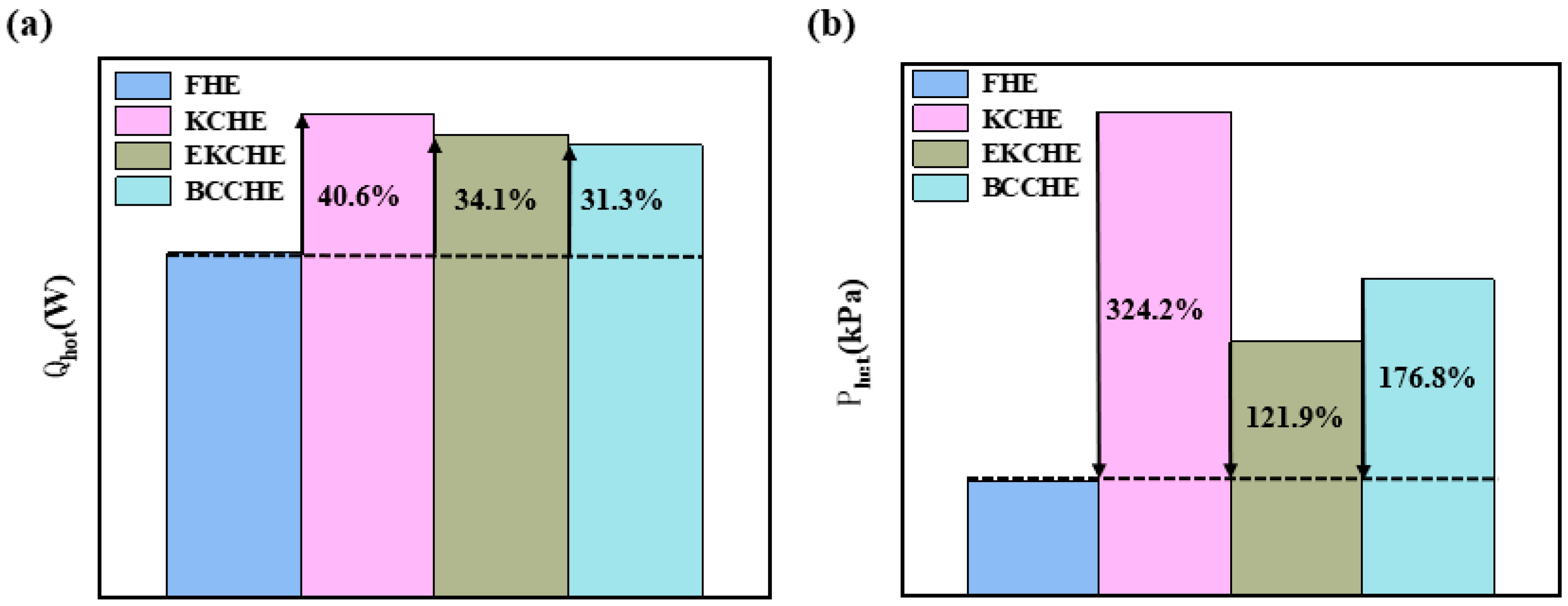
3.3. Heat Transfer and Pressure Drop of the Heat Exchanger

This study primarily focuses on the heat transfer and flow characteristics of the hot side in plate-fin heat exchangers. Using the traditional plate-fin heat exchanger (FHE) as a baseline, the overall thermal performance of three advanced configurations—the Kelvin cell heat exchanger (KCHE), the elliptical Kelvin cell heat exchanger (EKCHE), and the body-centered cubic heat exchanger (BCCHE)—were systematically evaluated. The KCHE demonstrates superior heat transfer enhancement, achieving a remarkable 40.6% improvement in heat transfer performance compared to the FHE, while the EKCHE and BCCHE showed increases of 34.1% and 31.3%, respectively (Figure 11). These enhancements are attributed to the geometric complexity of the lattice structures, which promote turbulent mixing and disrupt thermal boundary layers.
However, this improved thermal performance comes with a hydraulic loss. The pressure drop in the KCHE increased by 324.2% compared to the FHE, with the EKCHE and BCCHE exhibited pressure drop increments of 176.8% and 121.9%, respectively. The intricate geometry of the KC structure, while significantly enhancing convective heat transfer, introduces a substantial pressure drop due to the increased flow path tortuosity and localized flow separation. This phenomenon underscores a critical trade-off in engineering applications, whereby the thermal advantages of the KCHE must be carefully balanced against its hydraulic loss.
Figure 12 illustrates the temperature contour plots of the four heat exchangers, where the red zones represent high-temperature regions, the yellow zones indicate moderately high temperatures, and the green zones correspond to relatively low-temperature areas. From the contour maps, it can be seen that the internal temperature distribution of the FHE predominantly consists of red and yellow regions, suggesting the limited cooling effectiveness of the cold-side airflow on the hot-side airflow. In contrast, the BCCHE, EKCHE, and KCHE exhibit distinct green zones near the outlet sections, signifying an enhanced cooling performance. Notably, the KCHE demonstrates a sharp thermal gradient interface and broader low-temperature regions at both the core and entire outlet of the heat exchanger. This observation clearly demonstrates that porous medium-based heat exchangers (BCCHE, EKCHE, and KCHE) achieve superior thermal management compared to the conventional plate-fin design (FHE), with the KCHE exhibiting the most pronounced heat transfer enhancement due to its optimized geometric configuration.
Figure 13 delineates the pressure distribution characteristics across four heat exchanger configurations through total pressure contour plots and streamline patterns. The color spectrum ranges from red (highest pressure) to yellow (elevated pressure) to green (reduced pressure) to blue (lowest pressure). The FHE demonstrates a gradual pressure transition from inlet to outlet, maintaining predominantly red-dominated contours with smooth gradient transitions. In contrast, porous media-based configurations exhibit accelerated pressure dissipation, which is particularly evident through progressive color change from red/yellow in the porous zones to green/blue-dominated patterns at the outlets. Notably, the KCHE features the steepest pressure gradient demarcations, accompanied by the largest spatial extent of dark-blue low-pressure zones in the outlet contours.
In addition, the flow streamlines reveal vortex structures within the shell regions of all heat exchangers, which can be attributed to localized flow recirculation caused by high pressure drops at the core entrance. Contrary to conventional expectations, more pronounced vortices coincide with elevated local pressure zones near the vortex cores. This phenomenon suggests that stronger vortices may reduce the overall pressure drop by redistributing energy dissipation. However, the KCHE shows a less-prominent vortex activity in its shell region, implying lower localized pressure relief and consequently contributing to its higher global pressure drop. These observations align with the hydraulic performance trends, further validating the trade-off between enhanced heat transfer and elevated pressure drops in porous lattice designs.

3.4. Comprehensive Performance Comparison and Verification

In this study, the comprehensive performance evaluation of the heat exchanger focuses primarily on its core section, as the shell section’s design is predominantly governed by practical installation constraints. The core section operates within an average flow velocity range of 20–40 m/s, representing typical aerodynamic conditions for high-performance thermal management systems. The area goodness factor (j/f), which is a critical metric balancing heat transfer efficiency and pressure drop, is calculated across this velocity range and compared between the cell unit model and the full-scale heat exchanger, as illustrated in Figure 14.
At the unit scale (Figure 14a), the j/f factor of EKC configuration exhibits a pronounced advantage over KC and BCC designs. When the velocity is 10 m/s, EKCs improve the j/f factor by 25.61% over KCs; when the velocity is 80 m/s, EKCs improve the j/f factor by 45.45% over KCs. When the velocity is 10 m/s, the j/f factor of EKCs is 60.12% higher than that of the BCC cell; when the velocity is 80 m/s, the j/f factor of EKCs is 85.99% higher than that of the BCC cell. This enhancement underscores the EKCs’ superior ability to synergize turbulent heat transfer augmentation with minimized hydraulic penalties.
A heat exchanger core inlet velocity of 28 m/s was monitored in this study, so the j/f factors at this velocity were compared at the cell scale as well as at the heat exchanger scale, as shown in Figure 14b. In the cross-scale performance analysis, the EKCHE demonstrates exceptional stability in maintaining low pressure drop characteristics while progressively approaching the heat transfer efficiency of the KCHE at elevated flow velocities. The j/f in the heat exchanger scale agrees with the cell element calculations. At a velocity of 28 m/s, the j/f factors of the EKCs are 33.04% and 76.75% higher than those of the KCs and BCC cells, respectively. The j/f factors of the EKCHE are 24.11% and 61.48% higher than those of the KCHE and BCCHE, respectively. These results validate the applicability of the cross-scale simulation method for porous media, which effectively guides the optimal design of thermal hydraulics for elliptical Kelvin cells. It effectively separates heat transfer enhancement from excessive flow resistance. Consequently, at the heat exchanger core level, the EKCHE achieves a breakthrough improvement in energy efficiency compared to similar configurations.

4. Conclusions

This study comparatively investigates the heat transfer and pressure drop characteristics of KCs, EKCs, and BCC structures through simulation, alongside an analysis of the heat transfer performance of the KCHE, EKCHE, BCCHE, and FHE. The findings are summarized as follows.
In the comparative study of heat transfer performance, the Kelvin cell element (KC) demonstrates significant advantages in heat transfer characteristics. Its volumetric heat transfer coefficient is particularly prominent at low flow rates, which is significantly superior to that of the ellipsoidal improved structure (EKC). As the flow rate increases, the heat transfer gain effect of KCs gradually decreases, and the performance difference with EKCs tends to converge. Compared with the body-centered cubic structure (BCC), the heat transfer performance of the KCs shows an exponential increase, and the advantage is strengthened with the increase in flow rate. However, it should be noted that the pressure drop in KCs increases dramatically and nonlinearly with flow velocity, while EKCs show a significant improvement in pressure drop control. Furthermore, by utilizing a conventional plate-fin heat exchanger (FHE) as a baseline, the study replaces the serrated fins in the hot-side flow path with a lattice structure in order to create the KCHE, EKCHE, and BCCHE, all of which demonstrate an enhanced heat transfer performance compared to the FHE. Specifically, the KCHE achieves a 40.56% improvement in hot-side heat transfer capacity over the FHE. However, it incurs a 324% increase in hot-side pressure drop, which necessitates careful consideration in practical applications. In contrast, the EKCHE exhibits a more favorable pressure drop, increasing only 122% relative to the FHE, while also enhancing hot-side heat transfer capacity by 34.09%.
The overall performance of the three cells at both the cell unit and heat exchanger scales was also analyzed, revealing that EKCs and their corresponding EKCHE demonstrate superior combined heat transfer characteristics. Consequently, this study establishes a systematic numerical simulation methodology spanning from cell unit screening to heat exchanger design, providing new insights for the systematic design and investigation of porous media heat exchangers in related fields.
However, the high pressure drop brought about by porous media heat exchangers cannot be neglected. For example, the EKC structure exhibits the highest pressure drop; therefore, when considering the balance between heat transfer and pressure drop, the EKCHE has a better practical applicability in engineering design. Future research should further explore the adjustable porosity level, alternative cell geometries, and performance under different thermal conditions. In addition, topology optimization methods for porous media arrangement for flow channel design might be further considered.

Author Contributions

Conceptualization, J.Z.; Methodology, Y.L. (Yiqiang Liang) and Y.L. (Yu Liu); Formal analysis, M.S.; Resources, Y.S.; Writing—original draft, Y.L. (Yiqiang Liang); Writing—review & editing, J.Z.; Funding acquisition, Y.L. (Yu Liu) and M.S. All authors have read and agreed to the published version of the manuscript.

Funding

This work was supported by the Fundamental Research Funds for the Central Universities of China: No.DUT24BS015.

Data Availability Statement

The original contributions presented in this study are included in the article. Further inquiries can be directed to the corresponding author.

Conflicts of Interest

The authors declare no conflict of interest.

References

  1. Dixit, T.; Ghosh, I. An experimental study on open cell metal foam as extended heat transfer surface. Exp. Therm. Fluid Sci. 2016, 77, 28–37. [Google Scholar] [CrossRef]
  2. Liu, H.; Yu, Q.N.; Qu, Z.G.; Yang, R. Simulation and analytical validation of forced convection inside open cell metal foams. Int. J. Therm. Sci. 2017, 111, 234–245. [Google Scholar] [CrossRef]
  3. Fiedler, T.; Movahedi, N. Compact Aluminium Foam Heat Exchangers. Metals 2023, 13, 1440. [Google Scholar] [CrossRef]
  4. Sulong, M.A.; Ahmad, N.H.; Öchsner, A. Numerical Simulation of the Mechanical Properties of Syntactic Perforated Hollow Sphere Structures. In Proceedings of the 7th International Conference on Porous Metals and Metal Foams 2011, Busan, Republic of Korea, 18–21 September 2011. [Google Scholar]
  5. Li, Y.T.; Gong, L.; Xu, M.H.; Joshi, Y. Thermal Performance of Metal Foam Heat Sink with Pin Fins for Non-Uniform Heat Flux Electronics Cooling. In Proceedings of the 2019 35th Annual Semiconductor Thermal Measurement, Modeling and Management Symposium (SEMI-THERM), San Jose, CA, USA, 18–22 March 2019; pp. 30–37. [Google Scholar]
  6. Mahalle, A.M.; Jajoo, B.N. An approach for modeling and simulation of sintered Bronze foam sink for high heat dissipation. Appl. Therm. Eng. 2013, 51, 899–907. [Google Scholar] [CrossRef]
  7. Chen, A.; Gu, S.; Bennacer, R.; Liu, B. Study on Characteristics of Heat Transfer and Flow Resistance in Random Porous Foam Metal. In Proceedings of the XII International Conference on Computational Heat, Mass and Momentum Transfer (ICCHMT 2019), Rome, Italy, 3–6 September 2019; Mohamad, A., Taler, J., Benim, A.C., Bennacer, R., Suh, S.-H., de Lieto Vollaro, R., Vallati, A., Battista, G., Eds.; EDP Sciences: Les Ulis, France, 2019; p. 128. [Google Scholar]
  8. Ranut, P. On the effective thermal conductivity of aluminum metal foams: Review and improvement of the available empirical and analytical models. Appl. Therm. Eng. 2016, 101, 496–524. [Google Scholar] [CrossRef]
  9. Vishkaei, M.Y.; Javaherdeh, K. Experimental investigation of the effects of metal foam porous rings on non-Newtonian fluid flow in a double pipe heat exchanger. Int. Commun. Heat MASS Transf. 2024, 158, 107950. [Google Scholar] [CrossRef]
  10. T’joen, C.; De Jaeger, P.; Huisseune, H.; De Paepe, M. Thermo-Hydraulic Performance of a Heat Exchanger Consisting of Metal Foam Covered Tubes. In Proceedings of the ASME International Heat Transfer Conference—2010, Vol 4: Heat Transfer Measurement Techniques, Heat Transfer Equipment, Thermoelectrics, Washington, DC, USA, 8–13 August 2010; pp. 361–370. [Google Scholar]
  11. Zaib, F.; Ganesan, P.; Zaharinie, T.; Chen, Z.; Naganthran, K. Heat transfer performance of a compact heat exchanger based on metal foam and Thermal Interface Material (TIM). Int. J. Heat Mass Transf. 2024, 231, 125861. [Google Scholar] [CrossRef]
  12. Wang, W.; Guo, J.; Zhang, S.; Yang, J.; Ding, X.; Zhan, X. Numerical study on hydrodynamic characteristics of plate-fin heat exchanger using porous media approach. Comput. Chem. Eng. 2014, 61, 30–37. [Google Scholar] [CrossRef]
  13. Haider, P.; Freko, P.; Acher, T.; Rehfeldt, S.; Klein, H. Influence of inlet configuration and distributor geometry on the performance of cryogenic plate-fin heat exchangers. Appl. Therm. Eng. 2021, 195, 117197. [Google Scholar] [CrossRef]
  14. Chung, S.S.; Kim, N.; Jo, H. Effect of flow distribution on heat transfer in Printed Circuit Heat Exchangers using conjugate heat transfer model with a modified porous media approach. Appl. Therm. Eng. 2025, 266, 125540. [Google Scholar] [CrossRef]
  15. Schaedler, T.A.; Carter, W.B. Architected Cellular Materials. Annu. Rev. Mater. Res. 2016, 46, 187–210. [Google Scholar] [CrossRef]
  16. Xu, J.J.; Gao, Y.; Huang, H.; Yang, Q.; Guo, L.; Jiang, L. Diamond-structured hollow-tube lattice Ni materials via 3D printing. Sci. China-Chem. 2016, 59, 1632–1637. [Google Scholar] [CrossRef]
  17. Ho, J.Y.; Leong, K.C. Cylindrical porous inserts for enhancing the thermal and hydraulic performance of water-cooled cold plates. Appl. Therm. Eng. 2017, 121, 863–878. [Google Scholar] [CrossRef]
  18. Baishya, M.J.; Muthu, N.; Khanikar, P. In pursuit of a high-performance mechanical metamaterial: Simple-cubic-octahedral plate lattice. Int. J. Mech. Sci. 2024, 272, 109189. [Google Scholar] [CrossRef]
  19. Dhavale, A.A.; Lele, M.M. Numerical investigations on the impact of metallic foam configurations on heat transfer in double tube heat exchanger: A parametric approach. Numer. Heat Transf. Part A-Appl. 2024, 1–53. [Google Scholar] [CrossRef]
  20. Mishra, A.; Korba, D.; Kaur, I.; Singh, P.; Li, L. Prediction and Validation of Flow Properties in Porous Lattice Structures. J. Fluids Eng.-Trans. ASME 2023, 145, 0414024. [Google Scholar] [CrossRef]
  21. Buonomo, B.; di Pasqua, A.; Manca, O.; Sekrani, G.; Poncet, S. Numerical Analysis on Pressure Drop and Heat Transfer in Nanofluids at Pore Length Scale in Open Metal Porous Structures with Kelvin Cells. Heat Transf. Eng. 2021, 42, 1614–1624. [Google Scholar] [CrossRef]
  22. Calati, M.; De Monte, E.; Mancin, S. Numerical analysis of the effects of the structure shape and orientation of kelvin cell porous structures during air forced convection. Appl. Sci. 2021, 11, 6189. [Google Scholar] [CrossRef]
  23. Iasiello, M.; Bianco, N.; Chiu, W.; Naso, V. Anisotropy effects on convective heat transfer and pressure drop in Kelvin’s open-cell foams. In Proceedings of the 35th Italian-Union-of-Thermp-Fluid Dynamics (UIT) Heat Transfer Conference (UIT2017), Ancona, Italy, 26–28 June 2017; Ricci, R., DAlessandro, V., Eds.; IOP Science: Bristol, UK, 2017; p. 923. [Google Scholar]
  24. Sun, M.; Zhang, L.; Hu, C.; Zhao, J.; Tang, D.; Song, Y. Forced convective heat transfer in optimized kelvin cells to enhance overall performance. Energy 2022, 242, 122995. [Google Scholar] [CrossRef]
  25. Sun, M.R.; Yang, L.; Hu, C.Z.; Zhao, J.; Tang, D.; Song, Y. Simulation of forced convective heat transfer in Kelvin cells with optimized skeletons. Int. J. Heat Mass Transf. 2021, 165, 120637. [Google Scholar] [CrossRef]
  26. Shi, X.H.; Wang, L.X.; Chen, W.; Li, Z.; Chai, X.; Chyu, M.K. Effect of induced vortex and configuration layout on heat transfer enhancement of helium-xenon mixture. Appl. Therm. Eng. 2023, 225, 120168. [Google Scholar] [CrossRef]
  27. Corbett, T.M.; Thole, K.A. Large eddy simulations of kagome and body centered cubic lattice cells. Int. J. Heat Mass Transf. 2024, 218, 124808. [Google Scholar] [CrossRef]
  28. Najafi, H.; Najafi, B.; Hoseinpoori, P. Energy and cost optimization of a plate and fin heat exchanger using genetic algorithm. Appl. Therm. Eng. 2011, 31, 1839–1847. [Google Scholar] [CrossRef]
  29. Collins, I.L.; Weibel, J.A.; Pan, L.; Garimella, S.V. Evaluation of additively manufactured microchannel heat sinks. IEEE Trans. Compon. Packag. Manuf. Technol. 2018, 9, 446–457. [Google Scholar] [CrossRef]
  30. Schlegel, A.; Benz, P.; Buser, S. Wärmeübertragung und Druckabfall in keramischen Schaumstrukturen bei erzwungener Strömung. Heat Mass Transf. 1993, 28, 259–266. [Google Scholar] [CrossRef]
  31. Yang, Y.J.; Li, Y.Z.; Si, B.; Zheng, J.; Kang, R. Analysis of the Fin Performance of Offset Strip Fins Used in Plate-Fin Heat Exchangers. J. Heat Transf.-Trans. ASME 2016, 138, 101801. [Google Scholar] [CrossRef]
  32. Zhang, Z.D.; Yan, G.H.; Sun, M.R.; Li, S.; Zhang, X.; Song, Y.; Liu, Y. Forced convective heat transfer performance of foam-like structures-comparison of the Weaire-Phelan and the Kelvin structures with real metal foam. Int. J. Heat Mass Transf. 2024, 227, 125558. [Google Scholar] [CrossRef]
  33. Sheng, L.; Su, L.; Zhang, H.; Li, K.; Fang, Y.; Ye, W.; Fang, Y. Numerical investigation on a lithium ion battery thermal management utilizing a serpentine-channel liquid cooling plate exchanger. Int. J. Heat Mass Transf. 2019, 141, 658–668. [Google Scholar] [CrossRef]
  34. He, Y.L.; Jiang, T.; Du, S.; Xu, G. Research progress on performance boundary of air heat exchanger within flight envelope. Chin. J. Aeronaut. 2025, 46, 61–72. [Google Scholar]
  35. Dukhan, N.; Bagci, Ö.; Özdemir, M. Metal foam hydrodynamics: Flow regimes from pre-Darcy to turbulent. Int. J. Heat Mass Transf. 2014, 77, 114–123. [Google Scholar] [CrossRef]
  36. Zhang, Z.D.; Yan, G.H.; Sun, M.R.; Yan, H.; Zhao, J.; Song, Y.; Liu, Y. Pore-scale simulation of forced convection heat transfer in metal foams with uniform and gradient structures. Appl. Therm. Eng. 2023, 225, 120074. [Google Scholar] [CrossRef]
  37. Zhang, J.H.; Kundu, J.; Manglik, R.M. Effect of fin waviness and spacing on the lateral vortex structure and laminar heat transfer in wavy-plate-fin cores. Int. J. Heat Mass Transf. 2004, 47, 1719–1730. [Google Scholar] [CrossRef]
  38. Sun, M.R.; Yan, G.H.; Hu, C.Z.; Zhao, J.; Duan, F.; Song, Y. Thermal and hydraulic behaviours of Kelvin cells from metallic three-dimensional printing. Appl. Therm. Eng. 2023, 219, 119433. [Google Scholar] [CrossRef]
Figure 1. Morphological characterization of KCs, EKCs, and BCC cells.
Energies 18 03510 g001
Figure 2. Core structure dimensions of heat exchanger with heat exchanger elements for hot- and cold-side runners.
Energies 18 03510 g002
Figure 3. (a) Boundary conditions of the cell unit model. (b) Local mesh details.
Energies 18 03510 g003
Figure 4. (a) FloEFD grid level. (b) Base mesh of the heat exchanger. (c) Details of the seven-level global mesh refinement.
Energies 18 03510 g004
Figure 5. Comparison of (a) pressure drops and (b) Nusselt numbers between experimental data from the literature and simulation results in this study.
Energies 18 03510 g005
Figure 6. Pressure drops in KCs, EKCs, and BCCs.
Energies 18 03510 g006
Figure 7. (a) Fluid pressure distribution along the flow direction in each cell at 20 m/s. (b) Pressure distribution in the cell body skeleton at 20 m/s.
Energies 18 03510 g007
Figure 8. (a) Velocity distribution and velocity vectors at the cell body pores for KCs at 20 m/s. (b) Velocity distribution and velocity vectors at the cell body pores for EKCs at 20 m/s. (c) Velocity distribution and velocity vectors at the cell body pores for BCCs at 20 m/s.
Energies 18 03510 g008
Figure 9. (a) Heat transfer performance of each cell. (b) Magnitude of heat transfer enhancement.
Energies 18 03510 g009
Figure 10. Temperature contour maps of KCs, EKCs, and BCC cells at 20 m/s.
Energies 18 03510 g010
Figure 11. (a) Heat transfer rates on the hot side of four heat exchangers. (b) Pressure drops on the hot side of four heat exchangers.
Energies 18 03510 g011
Figure 12. Temperature contour plots of hot-side runners of four heat exchangers.
Energies 18 03510 g012
Figure 13. Total pressure contours and flow diagrams for four heat exchanger hot-side runners.
Energies 18 03510 g013
Figure 14. (a) j/f factor of the cell unit model. (b) j/f factors of two model scales at u = 28 m/s.
Energies 18 03510 g014
Table 1. Structural parameters of KCs, EKCs, and BCC cells.
Model φ ds (mm)a (mm)b (mm)SV (m2/m3)
KCs0.84980.4172.52.51867.14
EKCs0.84990.4972.551568.18
BCCs0.84930.4552.52.51339.25
Table 2. Mesh-independent verification of KC structures at 20 m/s.
n (106)ΔT (°C)DifferenceΔP (kPa)Difference
Case13.220.16 15.20%8.99 3.54%
Case24.319.10 9.13%9.01 3.33%
Case35.817.77 1.54%9.28 0.43%
Case48.117.50 -9.32 -
Table 3. The boundary conditions for heat exchangers.
ParameterValue
Hot side m l , h o t (kg/s)0.12
T h o t , i n (K)460
P h o t (kPa)460
Cold side m l , h o t (kg/s)0.24
T c o l d , i n (K)330
P c o l d (kPa)190
Table 4. Physical property parameters of GH3625.
Materialρ (kg/m3)Cp (kJ/kg·K)λs (W/m·K)
GH3625844043012.1
Disclaimer/Publisher’s Note: The statements, opinions and data contained in all publications are solely those of the individual author(s) and contributor(s) and not of MDPI and/or the editor(s). MDPI and/or the editor(s) disclaim responsibility for any injury to people or property resulting from any ideas, methods, instructions or products referred to in the content.

