Article

Numerical Optimization of the Coil Geometry in a Large-Scale Levitation Melting Device—With Titanium as a Case Study

by
Sławomir Golak
1,* and
Radosław Zybała
1,2
1
Department of Industrial Informatics, Faculty of Materials Engineering, Silesian University of Technology, Krasińskiego 8, 40-019 Katowice, Poland
2
Łukasiewicz Research Network—Institute of Non-Ferrous Metals, Sowińskiego 5, 44-100 Gliwice, Poland
*
Author to whom correspondence should be addressed.
Energies 2025, 18(15), 4162; https://doi.org/10.3390/en18154162
Submission received: 23 June 2025 / Revised: 21 July 2025 / Accepted: 1 August 2025 / Published: 5 August 2025
(This article belongs to the Special Issue Progress in Electromagnetic Analysis and Modeling of Heating Systems)

Abstract

Electromagnetic levitation melting offers the opportunity for the energy-efficient processing of reactive and high-purity metals. This paper concerns a new levitator design that significantly expands the achievable mass of molten metal by processing a toroidal load within a device featuring an annular trough-shaped coil. However, this unconventional arrangement necessitates the optimization of the coil’s geometry and supply current to ensure the stable levitation of the charge. This paper discusses the methodology for such optimization, considering two variants of coil geometry modification. This developed methodology was initially validated using numerical simulation, based on a two-physics, coupled 2D process model, with a 2.6 kg titanium toroidal charge as an example.

1. Introduction

Full levitation melting ensures the complete absence of contact between the processed metal and the crucible material, which could cause the contamination of the processed metal and, in the case of reactive metals, damage to the crucible [1,2,3,4,5,6]. At the same time, compared to semi-levitation melting, in which a water-cooled crucible is used [7,8,9,10,11,12,13], it potentially offers greater energy efficiency and a higher degree of metal overheating. However, despite the first proposals for such a solution appearing a hundred years ago [14,15], full levitation melting has not yet found practical application. The primary reason lies in the distribution of the alternating electromagnetic field within the typically used spiral coil with a vertical axis. In the axis of this coil, the field diminishes, and, consequently, the Lorentz forces supporting the load also disappear. For small masses, the lack of support in the central part of the charge’s bottom is compensated for by surface tension forces. However, as the mass of the charge increases, the hydrostatic pressure rises until it overcomes the resistance of the surface tension, leading to the leakage of the processed metal.
Various studies have been conducted on this process [16,17,18,19,20] and many attempts [21,22,23,24,25,26,27,28,29,30,31,32,33,34] have been made to modify the coil geometry in a levitation system with a quasi-static magnetic field. However, these attempts have not overcome the fundamental limitation of this solution—the lack of electromagnetic force support at the center of the load’s bottom—nor have they broken the mass barrier.
An interesting approach to addressing this issue is the use of a longitudinal electromagnetic levitator [35,36]. While this device still utilizes a coil with a vertical axis, its extension in the horizontal direction offers the potential to melt elongated charges with a greater mass than those achievable with a classic cylindrical coil. This is possible because increasing the load’s mass through its horizontal extension does not increase the hydrostatic pressure. Consequently, even with the field diminishing at the coil’s center, surface tension can prevent the leakage of molten metal.
A different solution, proposed by Spitans et al. [37,38,39], involves the complete reorientation of the electromagnetic field from vertical to horizontal. This approach aims to resolve the issue of insufficient load support along the vertical axis of the system. While this solution breaks the stagnation in levitation melting development, it has two potential weaknesses. Firstly, it necessitates a complex dual-frequency power supply system, which could hinder scalability. Secondly, the use of a rotating magnetic field may lead to complications in maintaining the stability of larger loads during melting.
A classic and simpler approach based on the standard quasi-static electromagnetic field is represented by a solution based on the reconstruction of the device’s coil geometry and the charge’s shape. This reconstruction aims to position the electromagnetic field decay zone outside the metal area. The solution utilizes an annular coil with a gutter cross-section, in which a torus-shaped charge is melted [40]. Consequently, the axis of the system, where the field diminishes, passes through the torus hole. While this device design effectively addresses the field decay problem, the necessity of maintaining the complex shape of the charge introduces new challenges in selecting the optimal coil geometry and power supply parameters. In [41], the solution adopted a fixed, a priori assumed coil geometry, and stable levitation was achieved by optimizing the four currents supplying separate coil sections. This enabled the stable levitation of a titanium load weighing over 2 kg. However, the four-channel power supply increases the demands on the power source and carries the risk of interactions between these channels.
This paper describes a much simpler design solution based on a single-channel power supply. The distribution of the electromagnetic field acting on the metal charge can also be controlled by modifying the coil geometry [42]. This approach enables an appropriate balance among the electromagnetic forces acting on the liquid charge for electromagnetic levitation melting, as demonstrated in the presented studies. The paper describes a two-level optimization methodology, in which the superior cycle of the target criterion describing the desired charge position is determined based on a time-expensive fully coupled process model, and the subordinate optimization cycles are based only on the electromagnetic submodel and the force balance criterion. The methodology has been numerically validated on the example of a 2.6 kg titanium charge.

2. Materials and Methods

This research investigated the melting of a 2.6 kg torus-shaped titanium charge in a levitation melting device equipped with an annular, trough-shaped coil. The properties of the titanium used in this research are presented in Table 1. Off-axis displacement of the metal leads to an imbalance in electromagnetic forces and surface tension, necessitating the optimization of the coil geometry and supply current to ensure the stable levitation of the metal within the desired device zone. The research explored two variants. Both focused on controlling the distance of the coil turns from the charge, but they differed in their control concepts and the potential technical methods of fabricating such a coil.

2.1. Variants of the Optimized Levitator

2.1.1. Levitation System with Four Rigid Coil Sections

Figure 1 illustrates the initial variant of the levitation melting system, featuring a variable distance between the coil sections and the melted load. The four sections are powered by the same current from a single-channel source. The uppermost coil section has a reversed current flow direction to prevent the molten metal from escaping upwards. The original, basic coil geometry is highlighted in yellow. The orange color indicates the coil sections that have been moved, with their assigned distances. As is evident, the geometry of a single section remains constant and is not subject to change during the modification process. It is assumed that only increases in distance are permissible during modification:
i , D I S T i 0
where D I S T i is the distace of the i-th coil section from the base position.
Creating such a coil on the appropriate matrices should be quite simple. The engineering challenge, however, will be connecting the individual sections into a single circuit powered by one source. Moreover, in the case of a real 3D coil (wound in a spiral), field inhomogeneity will occur at the ends of adjacent sections. At large scales of the device, the risk of charge leakage may arise from gaps between sections (especially the lower ones). However, as will be seen in the research results discussed below, for a 2.6 kg load, such a gap is small.

2.1.2. Levitation System with Two Coil Sections Featuring Controlled Winding Envelope

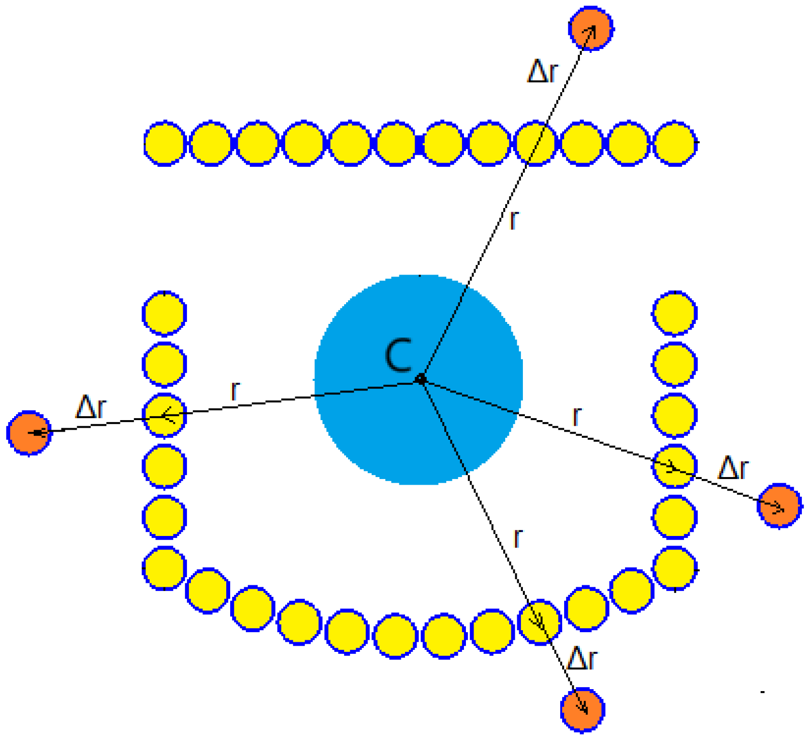
The presence of gaps between sections and the associated potential problems, as indicated in the previous variant, led to the proposal of the second solution. In this solution, only two coil sections are employed: a lower supporting one and an upper securing one (with opposite directions of current flow). Balancing the forces acting on the load is achieved by changing the shapes of these two sections, where the position of each coil is controlled by a polynomial envelope. Figure 2 illustrates the concept of determining the distance of each turn from the original coil geometry. The base position of each coil (yellow) is determined by the radius vector r . The starting point C of this radius lies at the center of the desired load position. The modified position of a given coil (orange) is determined along the direction of the radius vector at a distance Δ r .
The shape of each of the two coil sections is described by a polynomial. For the lower, supporting coil, with a more complex shape, a second-degree polynomial is used:
c i = a 1 i 2 + a 2 i
c ^ i = c i min i c i
Δ r L , i = r L , i 1 + c ^ i
where r L , i and Δ r L , i are the radius vector of the i-th turn of the lower coil section and its change, c i is the radius change coefficient, and c ^ i is the scaled radius increase coefficient.
The shift (3) ensures that, for each modified coil turn, the change in the radial extent will be non-negative. For the upper, simpler protection section, only a first-degree polynomial was used:
d i = b 1 i
d ^ i = d i min i d i
Δ r U , i = r U , i 1 + d ^ i
where r U , i and Δ r U , i are the radius vector of the i-th turn of the upper section and its change, d i is the radius change coefficient, and d ^ i is the scaled radius increase coefficient.
This solution ensures the continuous, smooth shape of the lower coil without any gaps. The coil geometry is described by only three parameters compared to the previous variant, where four parameters were used.

2.1.3. Levitator Application Scenario

Figure 3 shows a schematic diagram illustrating the use of the new levitator, regardless of the method used to determine the coil’s geometry. It is assumed that the feedstock will be a torus-shaped charge, prepared in a different metallurgical process. During levitation melting, the charge can be heated to a degree of superheating determined by the technological recipe. This process will allow the metal to remain superheated for a desired period, facilitating its internal chemical transformation, whether spontaneous or induced by the introduction of specific chemical additives. The liquid metal will be poured from the levitator into the final mold by gravity after the coil rotates. Maintaining power to the coil during the transfer will minimize contact between the liquid, reactive metal and the refractory material surrounding and protecting the coil. This material should be resistant to such temporary contact with the metal.

2.2. Numerical Model

The levitator optimization process requires the definition of measures describing this device, acting as criteria. Leaving aside trivial, theoretical solutions, it is necessary to build a numerical model describing phenomena that are important for the implemented process. Such a model is also necessary for the initial, numerical validation of the solution determined in the optimization process.
The two-physics electromagnetic modeling of processes involving a free liquid metal surface requires taking into account the strong, bidirectional coupling between the hydrodynamic and electromagnetic submodels [19,43,44,45,46,47]. This is due to the fact that the shape of the liquid metal changes under the influence of electromagnetic forces. At the same time, changing the shape of the conductive charge changes the distribution of the electromagnetic field that results in these electromagnetic forces.
The parent model is the hydrodynamic submodel, which, in a non-stationary mode, determines the time-dependent changes in metal flow and, above all, its shape. For each time step of the hydrodynamic simulation, the electromagnetic submodel is invoked, receiving the current geometry of the liquid metal. This submodel calculates the distribution of Lorentz electromagnetic forces acting on the liquid metal and passes this information to the hydrodynamic model. This exchange cycle continues throughout the simulation.
The electromagnetic submodel was based on the magnetic vector potential equation, which was solved in the frequency domain:
× 1 μ × A + j ω σ A = J s
where A is the complex magnetic vector potential, μ is the magnetic permeability, σ is the electric conductivity, ω is the angular frequency, and J s is the complex current density source.
Based on the calculated potential A distribution, the distribution of magnetic induction B and current density J is determined:
B = × A ,
J = j ω σ A .
Knowing the complex current density and the induction, one can obtain the volume density of the Lorentz force acting on the molten metal:
f L = 1 2 R e J × B *
The hydrodynamic submodel was based on the Navier–Stokes momentum conservation Equation (12) for incompressible fluids. One of the source terms is the volume density of the Lorentz force f L acting on the liquid metal, realizing one direction of coupling between the EM and HD submodels:
t ( ρ v ) + · ( ρ v v ) = p + · η e f f v + v T + f L + f S + ρ g
where ρ is the fluid density, v is the fluid velocity, p is the pressure, η e f f is the effective viscosity determined from the k- ω turbulence model, f S is the surface tension force, and g is the gravity.
The dynamics of the free surface of the liquid metal taking into account surface tension were determined based on the Volume of Fluid (VOF) method [48]. This method introduces an additional volume fraction equation:
α m t + · ( α m v ) = 0
where α m is the volume fraction of the metal phase,
In the VOF method, material properties—namely, density ρ and viscosity η —are determined based on a weighted average of the volume fraction and the properties of the metal phase and atmosphere:
ρ = α m ρ m + ( 1 α m ) ρ a
η = α m η m + ( 1 α m ) η a
where ρ m and ρ a are the densities of the liquid metal and atmosphere, respectively, and η m and η a are the dynamic viscosities of the metal and atmosphere.
The volume fraction distribution of the metallic phase is used to implement the second direction of coupling of the EM and HD submodels. The metal charge shape is transferred to the EM submodel by the conductivity distribution determined from the volume fraction distribution of the metal phase:
σ = α m σ m + ϵ
where σ sigma is the electrical conductivity for the potential metal presence region used in Equations (8) and (10), σ m is the conductivity of the molten metal, and ϵ is a small value to ensure numerical stability.
The numerical simulation system used in the research was created based on existing software, coupled with the authors’ own code. The electromagnetic submodel was implemented using the open-source GetDP software [49,50], while the hydrodynamic submodel was based on the commercial software Ansys Fluent.
The metal charge is a toroid with full axial symmetry. The actual 3D coil will be a spiral winding, and its overall shape will conform to a surface of revolution. The envelope of this winding will also maintain axial symmetry. With an appropriate coil density, the slight vertical displacement of individual turns around the circumference is assumed to have a negligible impact on the electromagnetic field distribution. This assumption is commonly made for devices with global axial symmetry and coils composed of solid turns that are significantly smaller than the entire coil. Due to this geometry of the device, in order to shorten the simulation time, the calculations were performed in a simplified axisymmetric 2D space.

2.3. Optimization Methodology

The above model was used to determine the criteria for the optimization of the two considered levitator systems. The optimization aimed to achieve a stable position for the molten, lifted load within the device. Determining the liquid load’s position necessitates the implementation of optimization based on non-stationary simulation, utilizing a full, coupled process model. Such a simulation is time-consuming, and using a criterion based on it would result in an unacceptably long time required to obtain a solution. Therefore, in the discussed optimization of the coil geometry, the idea proposed in [41] was adopted. This approach involves using a surrogate criterion within the internal cycle of the hierarchical optimization system. This subcriterion can be quickly determined solely based on the electromagnetic model.

2.3.1. Distances of Entire Rigid Coil Sections

In the case of the first variant of the electromagnetic levitation system, five solution parameters were optimized:
  • distance of the left section from the base position (DIST 1);
  • distance of the lower section from the base position (DIST 2);
  • distance of the right section from the base position (DIST 3);
  • distance of the top section from the base position (DIST 4);
  • current supplying all coil sections (CURRENT).
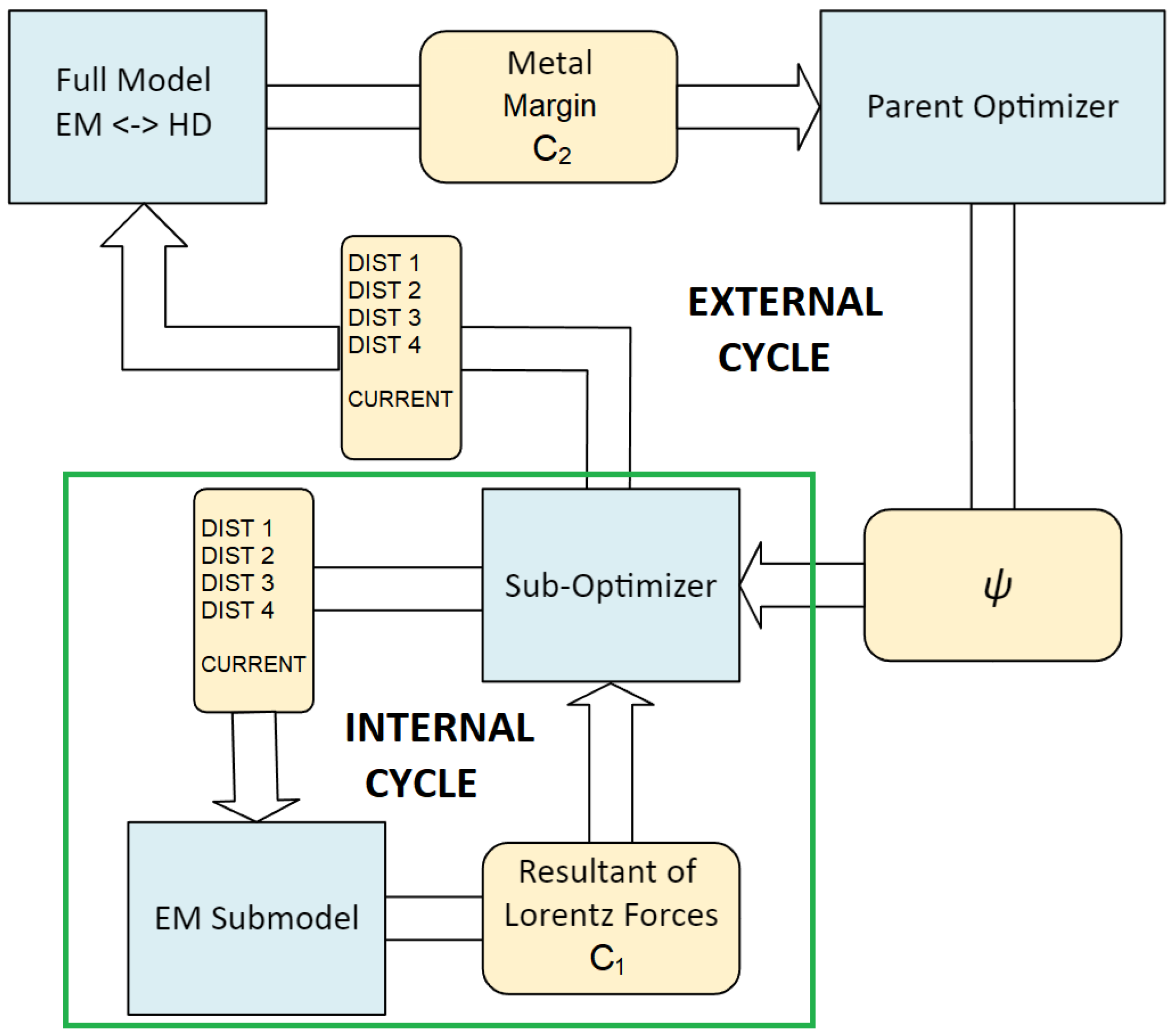
The hierarchical optimization system that accomplishes this task is shown in Figure 4. The majority of the search for a solution is carried out by the internal optimization cycle, marked with a green rectangle. This cycle is based on the popular Nelder–Mead algorithm [51], which works well in optimizing solutions with a small number of parameters. In the authors’ previous research on levitator optimization, this algorithm proved to be the most effective in the case of a parameter space of similar dimensions [41]. Aside from its efficiency and limited computational demands for criterion evaluation, its most significant advantage—especially when dealing with criteria determined by a complex numerical model—is that it does not require the determination of partial derivatives of the criterion with respect to the solution parameters (i.e., the gradient of the solution hypersurface).
The internal optimization cycle uses a surrogate criterion, determinable within the faster electromagnetic submodel. This minimized criterion consists of two components: one expressing the balance of axial forces (electromagnetic and gravity, Equation (17)) and another for radial forces (electromagnetic only; Equation (18)):
C a = ρ m g V + V f LF · u ^ a d V = 0
C r = V f LF · u ^ r d V + ψ = 0
C 1 = C a 2 + C r 2
where V is the metal volume, ρ m is the metal density, g is gravity acceleration, u ^ a is the axial unit vector, and C 1 is the combined surrogate criterion for the internal optimization cycle.
Internal optimization, based on the electromagnetic model, is performed for a torus-shaped charge with an ideal circular cross-section, placed at the desired position in the device. In the actual process (which is only describable by the full, coupled model), the metal undergoes deformation and displacement. Therefore, the coil geometry determined for such a load will not provide the stable levitation of the deformed load. Preliminary experiments have shown that load deformation primarily disturbs the balance of radial force components. Consequently, the equation includes a correction factor, ψ , for this balance. Its value is determined based on the superior, main optimization cycle using expensive, coupled magnetohydrodynamic simulation. However, since we are dealing with a search in a one-dimensional space, the value of the coefficient ψ can be determined in several iterations using the golden-section search method [41].
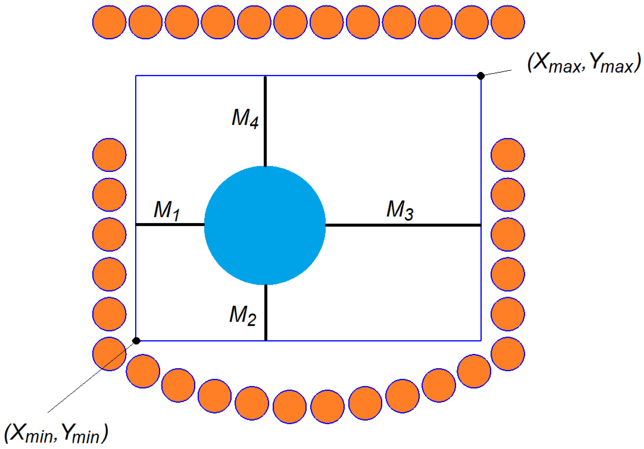
The purpose of the external optimization cycle is to position the metal so as to maintain the largest possible margin on all sides from the boundaries of the area where the charge presence is required. The individual margins, as shown in Figure 5, are determined by the following formulas:
M 1 ( t ) = min i α m , i ( t ) > 0 x i w i α m , i ( t ) 0.5 X m i n ,
M 2 ( t ) = min i α m , i ( t ) > 0 y i y i α m , i ( t ) 0.5 Y m i n ,
M 3 ( t ) = X m a x max i α m , i ( t ) > 0 x i w i α m , i ( t ) 0.5 ,
M 4 ( t ) = Y m a x max i α m , i ( t ) > 0 y i w i α m , i ( t ) 0.5
where α m , i ( t ) is the volume fraction of metal in the i-th cell at simulation time t; x i and y i are the coordinates of the cell centroid; w i and h i are the width and height of the cell; and X m i n , X m a x , Y m i n , Y m a x are the boundaries of the allowable area.
The value of the main optimization criterion to be maximized this time is defined as the smallest of the four margins in the period after charge levitation stabilization t s t a b (i.e., once the initial oscillations disappear):
C 2 = min t > t s t a b min M 1 ( t ) , M 2 ( t ) , M 3 ( t ) , M 4 ( t )

2.3.2. Smooth Winding Envelope of Two Coil Sections

In the second variant of the electromagnetic levitation system, four solution parameters were optimized:
  • two second-degree polynomial coefficients for the lower coil section ( a 1 and a 2 );
  • one first-degree polynomial coefficient for the upper coil section ( b 1 );
  • the current supplying the two coil sections (CURRENT).
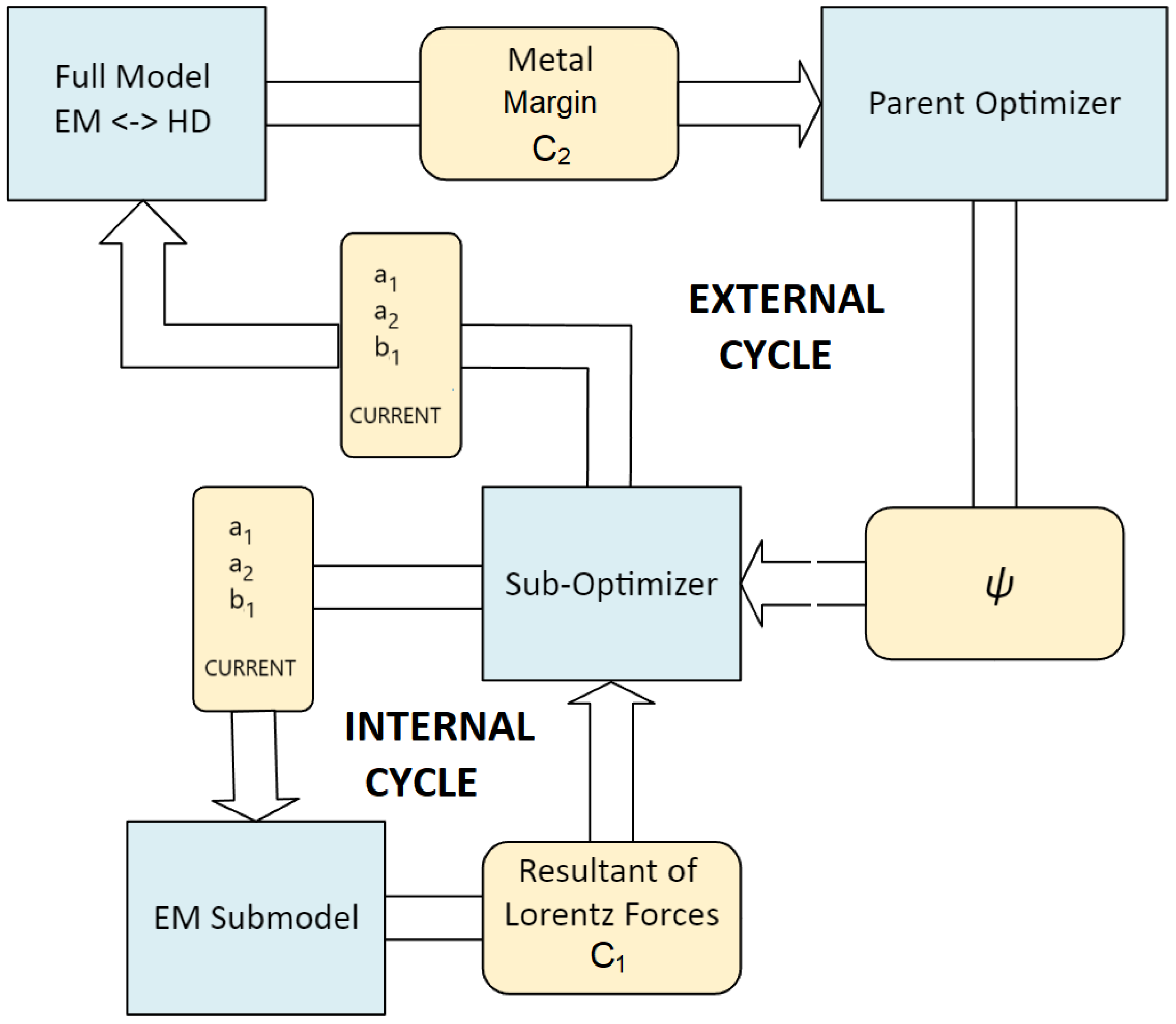
The hierarchical optimization system itself remains essentially unchanged, except for the solution parameters transferred in the optimization cycles (Figure 6). The criteria for the internal ( C 1 , Equation (19)) and external optimization cycle ( C 2 , Equation (24)) remain the same. The inner cycle was again implemented using the Nelder–Mead algorithm, while the outer one utilized the golden-section search method [41].

2.3.3. Validation Method

The ideal way to validate the determined geometry of levitator coils would be to build a real device. However, this is not possible at this stage of development. It is necessary to design a custom physical coil, auxiliary components, and a power source and then purchase and manufacture these components. This was beyond the scope of the current research, which aimed to initially confirm the feasibility of conducting a stable levitation process in a levitator based on the new concept. For this reason, the simplified validation was based on a two-physics model, which is a component of the optimization system. This model reproduces all hydrodynamic and electromagnetic phenomena relevant to process stability for the liquid metal stage in a simplified 2D space. It was assumed that, if a stable metal position and shape can be maintained during a process simulation based on this model (described in Section 2.2), then a fundamental condition necessary for the potential implementation of real-world reactive metal processing is fulfilled.

3. Results and Discussion

Studies confirming the optimization methodology developed for both variants of levitation systems were conducted for identical 2.6 kg titanium charges. In both cases, the coil was supplied with a current of 10 kHz. The current intensity was the subject of the optimization.

3.1. Optimization of Distances of All Four Coil Sections

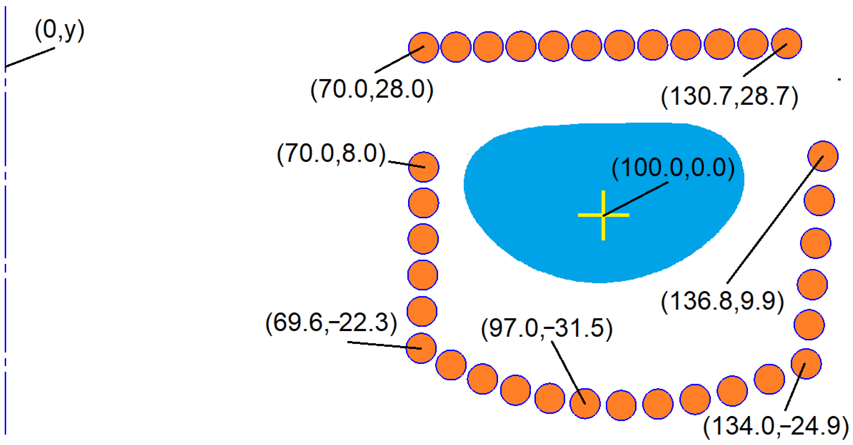
Figure 7 displays the geometry of the optimized arrangement of four rigid coil sections. Analyzing this drawing and the optimal solution parameters presented in Table 2, it can be observed that, in principle, only the third (right-hand) coil section and the upper (safety) section were moved to a very small extent. The ψ correction factor, determined in the external optimization cycle, was 4.25 N.
The left column of Figure 8 illustrates the evolution of the metal shape during the process and the distribution of Lorentz electromagnetic forces acting on the metal in the optimized variant of the levitation system. As can be observed, the charge has flattened, and its cross-section has undergone some twisting. Nevertheless, throughout the presented period of the process, Lorentz forces consistently provide support for the bottom of the load. The inhibitory effect of the upper section of the coil, preventing the upward push of the charge, is also discernible.
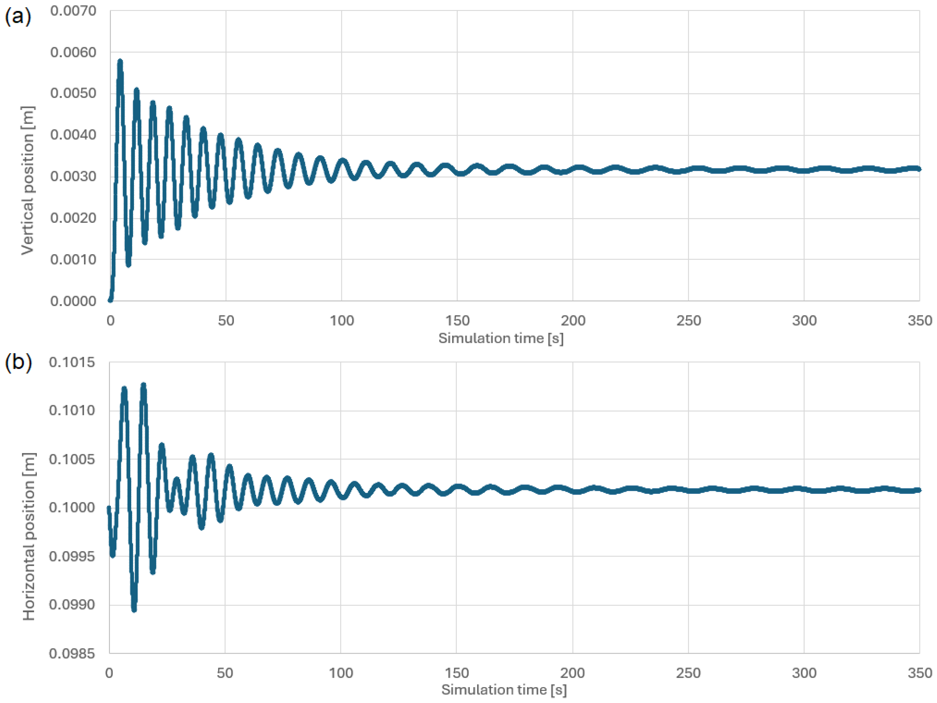
Figure 9 displays changes in the position of the centroid of the charge cross-section (vertical and horizontal components) over time. As can be seen, the strong deformation of the metal’s original shape leads to observed oscillations in the charge’s position. These oscillations, however, exhibit a tendency toward self-damping.
The first row of Table 3 shows the Joule heat lost in the coil and heating the charge for the analyzed variant with the coil divided into four sections. The given device efficiency is the ratio of the heat released in the charge to the supply power.
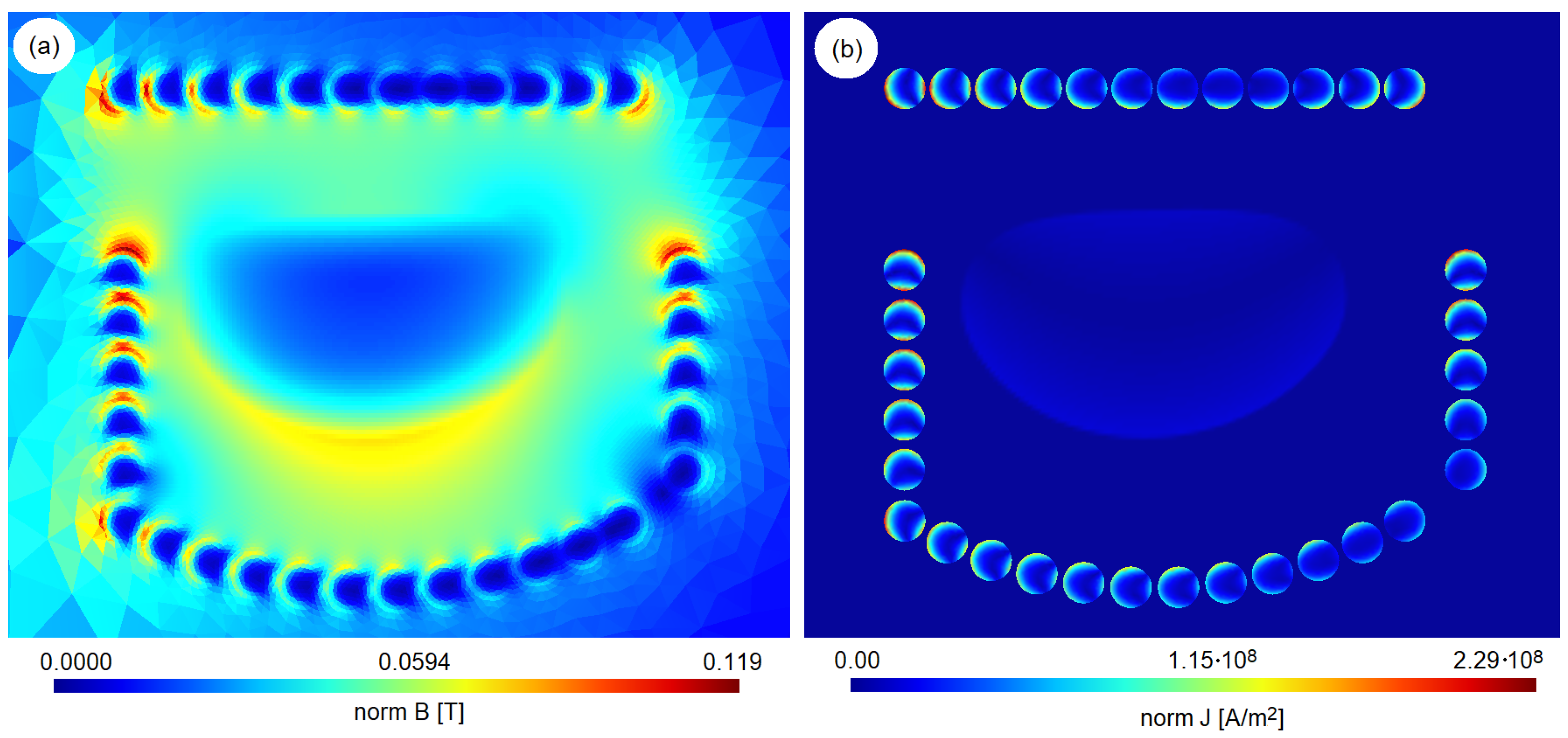
Figure 10 shows the distribution of the current density and induction for the analyzed device variant after a period of 200 s. The current distribution in the charge coincides with the Lorentz force distribution from Figure 8. Characteristically, the current densities in the charge are much lower than those in the inductor.

3.2. Optimization of Smooth Winding Envelope with Two Coil Sections

Figure 11 shows the geometry of the optimized coil with two envelope-controlled shape sections. The coefficients of the polynomial defining the envelopes are shown in Table 4. The shape correction coefficient has changed very little compared to the previous coil variant. The current values supplying both types of coils are also similar.
The right column in Figure 8 illustrates the time evolution of the metal shape and electromagnetic force distribution for the analyzed levitation melting system. The slight twisting of the metal cross-section is observable compared to the previous variant. Again, decaying oscillations in the centroid position of the charge cross-section can be observed (Figure 12).
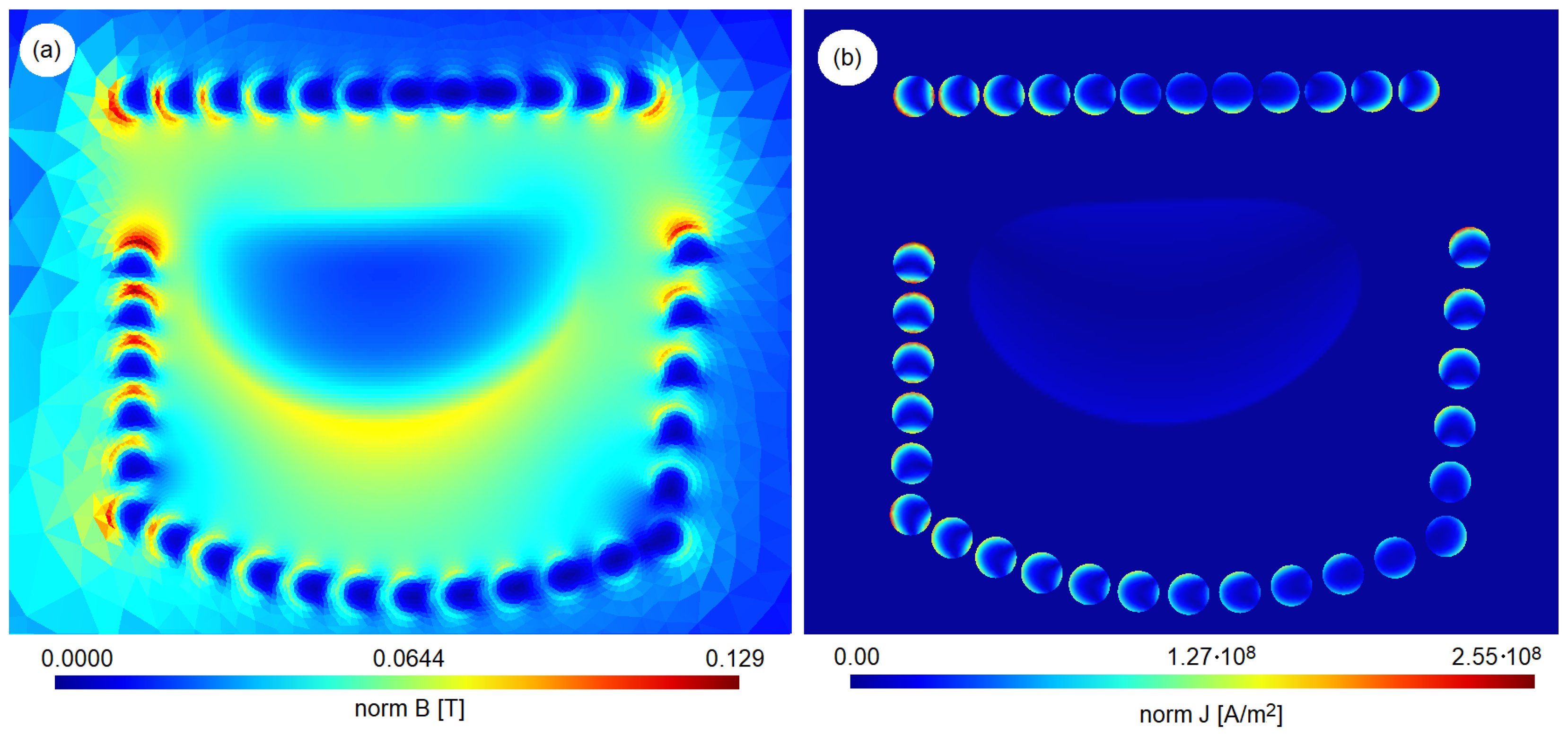
Comparing the efficiency of the second variant of the levitator (with two coil sections) to the first variant, which has four sections, reveals no significant change (see the second and first rows in Table 3, respectively). The change in heat output results from the increased coil supply current in the second variant (compare Table 2 with Table 4). The distribution of the current density and induction field for the device with two coil sections (Figure 13) does not differ qualitatively from that for the levitator with four sections (Figure 10).
For both variants, a single internal optimization cycle (determining the force balance criterion based solely on the electromagnetic submodel) took approximately 1 s. The duration of a single external optimization cycle (which involved determining the charge position criterion using a full two-physics model, a non-stationary simulation, and one internal optimization of the force balance) was approximately 6 h. This approach allowed us to complete the entire levitator optimization in under 60 h on a computer with an AMD Ryzen 9 7950X 16-core processor.

4. Conclusions

This paper presents a methodology for the optimization of coil geometries in an electromagnetic levitation melting system, along with the numerical model used for this optimization. The studies have demonstrated that the stable levitation of a 2.6 kg titanium load (formed into a toroid with an initial main radius of 100 mm and a cross-sectional radius of 18 mm) can be achieved in the new system by optimizing only the coil geometry, powered by a single-channel power source (403 A for the four-section variant and 439 A for the two-section variant). Both analyzed variants were based on different implementations in terms of selecting the distance between the coil turns and the metal. The primary aim was to achieve a balance between the electromagnetic and gravitational forces acting on the metal charge, thereby maintaining it in the desired position. Despite the different implementations, a common feature of the optimized geometries is the increased distance of the outer coil turns (relative to the system axis) from the load.
For optimization efficiency, the studies utilized an axisymmetric 2D model of the process, which involved some simplification. This simplification is associated with certain limitations, such as the inability to analyze phenomena that lack axial symmetry, like a break in the continuity of the charge circuit or an asymmetric disturbance in its equilibrium. Additionally, the model does not account for thermal effects, including changes in charge properties due to temperature, melting, or heat loss through radiation. However, this approach allowed for the preliminary confirmation of the concept’s validity, and, given a sufficient turn density, this simplification appears sufficiently representative for the optimization of the considered device. The above simplifications, along with the hierarchical optimization system (which includes both internal and external cycles), enabled a solution to be obtained within an acceptable time frame of less than 60 h.
The tests were conducted using a 2.6 kg titanium sample. Nevertheless, it is expected that the proposed device design, coupled with this optimization method, could be applied to various metals and masses, limited only by the available power source.
The aim of this research was to provide preliminary validation of the concept of achieving stable charge levitation solely by optimizing the coil geometry powered by a typical single-channel current source. The simplified validation was based solely on numerical simulation. This is, of course, a significant simplification, but the methodology for the numerical simulation of the levitation melting process is sufficiently well developed to allow for the preliminary validation. The solutions developed will allow for continued work towards the design and implementation of a real device.

Author Contributions

Methodology and investigation, S.G.; visualization, R.Z.; writing, S.G. and R.Z. All authors have read and agreed to the published version of the manuscript.

Funding

Publication supported by the Excellence Initiative—Research University program implemented at the Silesian University of Technology, year 2025, grant no. 11/040/SDU/10-21-02.

Institutional Review Board Statement

Not applicable.

Informed Consent Statement

Not applicable.

Data Availability Statement

Dataset available on request from the authors.

Conflicts of Interest

The authors declare no conflicts of interest.

References

  1. Friedrich, B.; Morscheiser, J.; Lochbichler, C. Potential of ceramic crucibles for melting of titanium-alloys and gamma-titaniumaluminide. In Proceedings of the 51st International Colloquium on Refractories, Aachen, Germany, 15–16 October 2008; pp. 229–232. [Google Scholar] [CrossRef]
  2. Schaffoener, S.; Aneziris, C.G.; Berek, H.; Hubalkova, J.; Rotmann, B.; Friedrich, B. Corrosion behavior of calcium zirconate refractories in contact with titanium aluminide melts. J. Eur. Ceram. Soc. 2015, 35, 1097–1106. [Google Scholar] [CrossRef]
  3. Schafföner, S.; Aneziris, C.G.; Berek, H.; Rotmann, B.; Friedrich, B. Investigating the corrosion resistance of calcium zirconate in contact with titanium alloy melts. J. Eur. Ceram. Soc. 2015, 35, 259–266. [Google Scholar] [CrossRef]
  4. Fashu, S.; Lototskyy, M.; Davids, M.W.; Pickering, L.; Linkov, V.; Tai, S.; Renheng, T.; Fangming, X.; Fursikov, P.V.; Tarasov, B.P. A review on crucibles for induction melting of titanium alloys. Mater. Des. 2020, 186. [Google Scholar] [CrossRef]
  5. Kamyshnykova, K.; Lapin, J. Vacuum induction melting and solidification of TiAl-based alloy in graphite crucibles. Vacuum 2018, 154, 218–226. [Google Scholar] [CrossRef]
  6. Song, Q.; Liang, T.; Qian, K.; Xing, W.; Zha, X.; Chen, B.; Ma, Y.; Liu, K. Corrosion resistance of calcium zirconate crucible to titanium-copper melts. J. Eur. Ceram. Soc. 2022, 42, 3321–3331. [Google Scholar] [CrossRef]
  7. Bulinski, P.; Smolka, J.; Golak, S.; Przylucki, R.; Blacha, L.; Bialecki, R.; Palacz, M.; Siwiec, G. Effect of turbulence modelling in numerical analysis of melting process in an induction furnace. Arch. Metall. Mater. 2015, 60, 1575–1579. [Google Scholar] [CrossRef]
  8. Guglielmi, M.; Baake, E.; Köppen, A.; Holzmann, E.; Herbst, S.; Maryamnegari, S.M. Induction melting in a cold crucible furnace applied to innovative high-melting temperature metals. Magnetohydrodynamics 2022, 58, 523–532. [Google Scholar] [CrossRef]
  9. Bojarevics, V.; Nishimura, T.; Matsuwaka, D. Development of advanced cold crucible melting of titanium alloys. Magnetohydrodynamics 2022, 58, 13–24. [Google Scholar] [CrossRef]
  10. Witteveen, J.P.; Vrielink, M.A.B.; van Gastel, R.; van Houselt, A.; Zandvliet, H.J.W. Containerless metal single-crystal growth via electromagnetic levitation. Rev. Sci. Instrum. 2021, 92, 105105. [Google Scholar] [CrossRef]
  11. Zhang, C.; Cao, F.; Zhang, L.; Jin, Z.; Cao, G.; Qiu, Z.; Shen, H.; Huang, Y.; Jiang, S.; Sun, J. Break the superheat temperature limitation of induction skull melting technology. Appl. Therm. Eng. 2023, 220. [Google Scholar] [CrossRef]
  12. Zhang, C.; Zhang, L.; Cao, F.; Jin, Z.; Cao, G.; Shen, H.; Huang, Y.; Sun, J. Optimizing energy efficiency in induction skull melting process: Investigating the crucial impact of melting system structure. Sci. Rep. 2024, 14, 6303. [Google Scholar] [CrossRef]
  13. Wang, G.; Bai, Y.; Zhao, B.; Li, L.; Liu, Y.; Zhang, K.; Liu, Y.; Yu, K. Improve the performance of cold crucible used for emissivity measurement of molten metal. Case Stud. Therm. Eng. 2025, 68, 105898. [Google Scholar] [CrossRef]
  14. Muck, O. Verfahren und Vorrichtung zum Schmelzen, Insbesondere von Leitern u. dgl. Durch Elektrische Induktionsstroeme. German Patent 422004, 30 October 1923. [Google Scholar]
  15. Okress, E.C.; Wroughton, D.M.; Comenetz, G.; Brace, P.H.; Kelly, J.C.R. Electromagnetic Levitation of Solid and Molten Metals. J. Appl. Phys. 1952, 23, 545–552. [Google Scholar] [CrossRef]
  16. Matson, D.; Battezzati, L.; Galenko, P.; Gandin, C.A.; Gangopadhyay, A.; Henein, H.; Kelton, K.; Kolbe, M.; Valloton, J.; Vogel, S.; et al. Electromagnetic levitation containerless processing of metallic materials in microgravity: Rapid solidification. NPJ Microgravity 2023, 9, 65. [Google Scholar] [CrossRef]
  17. Snikeris, J.; Apsitis, A.; Pumpurs, A.; Lacis, U.; Kravchenko, S.; Silamikelis, V. Experimental observation of the vertical displacement between heating and levitation regions in an electromagnetic levitation coil. J. Phys. D Appl. Phys. 2024, 57, 095002. [Google Scholar] [CrossRef]
  18. Pang, X.; Zhang, G.; Yan, P.; Xiao, Z.; Wang, X. Study on the Migration Patterns of Oxygen Elements during the Refining Process of Ti-48Al Scrap under Electromagnetic Levitation. Materials 2024, 17, 3709. [Google Scholar] [CrossRef]
  19. Wang, X.; Zhang, G.; Yan, P.; Pang, X.; Xiao, Z. Numerical Simulation of Electromagnetic–Thermal–Fluid Coupling for the Deformation Behavior of Titanium–Aluminum Alloy under Electromagnetic Levitation. Materials 2024, 17, 3338. [Google Scholar] [CrossRef]
  20. Brillo, J.; Yang, F.; Holland-Moritz, D. Transport property measurement of liquid metals and alloys using electromagnetic and electrostatic levitation. Int. J. Thermophys. 2024, 45, 17–32. [Google Scholar] [CrossRef]
  21. Peifer, W.A. Levitation melting. A Survey of the State-of-the-Art. JOM 1965, 17, 487–493. [Google Scholar] [CrossRef]
  22. Brace, P.H. Apparatus for the Magnetic Levitation and Heating of Conductive Materials. US2664496A, 29 December 1953. [Google Scholar]
  23. El-Kaddah, N.; Szekely, J. The electromagnetic force field, fluid flow field, and temperature profiles in levitated metal droplets. Metall. Trans. B 1983, 14, 401–410. [Google Scholar] [CrossRef]
  24. Sun, H.; Pehlke, R.D. Coil Design for Lower Temperature Levitation Melting of Iron Alloys. High Temp. Mater. Processes 2000, 19, 41–48. [Google Scholar] [CrossRef]
  25. Bojarevics, V.; Pericleous, K. Modelling electromagnetically levitated liquid metal droplets. Magnetohydrodynamics 2003, 39, 437–450. [Google Scholar]
  26. Royer, Z.L.; Tackes, C.; LeSar, R.; Napolitano, R.E. Coil optimization for electromagnetic levitation using a genetic like algorithm. J. Appl. Phys. 2013, 113, 214901. [Google Scholar] [CrossRef]
  27. Feng, L.; Shi, W.Y. The Influence of Eddy Effect of Coils on Flow and Temperature Fields of Molten Droplet in Electromagnetic Levitation Device. Metall. Mater. Trans. B. 2015, 46, 1895–1901. [Google Scholar] [CrossRef]
  28. Gao, L.; Shi, Z.; Li, D.; Zhang, G.; Yang, Y.; McLean, A.; Chattopadhyay, K. Applications of Electromagnetic Levitation and Development of Mathematical Models: A Review of the Last 15 Years (2000 to 2015). Metall. Mater. Trans. B. 2015, 47, 537–547. [Google Scholar] [CrossRef]
  29. Feng, L.; Shi, W.Y. Influence of Coil Angle Arrangement on Dynamic Deformation and Stability of Molten Droplet in Electromagnetic Levitation System. ISIJ Int. 2016, 56, 50–56. [Google Scholar] [CrossRef]
  30. Witteveen, J.; van Gastel, R.; van Houselt, A.; Zandvliet, H. 3D modeling of electromagnetic levitation coils. Curr. Appl. Phys. 2021, 32, 45–49. [Google Scholar] [CrossRef]
  31. Nie, W.; Liu, J.; Wang, L.; Zhang, T.; Liu, B.; Liu, Y.; Zhang, Y. Induction Smelting Cold Crucible with Full Suspension and Strong Stirring Capacity. CN112393588A, 23 February 2021. [Google Scholar]
  32. Pons, R.; Gagnoud, A.; Chaussende, D.; Budenkova, O. Design of a coil for electromagnetic levitation: Comparison of numerical models and coil realization. Magnetohydrodynamics 2022, 58, 55–64. [Google Scholar] [CrossRef]
  33. Nycz, B.; Przylucki, R.; Malinski, L. Comparison of Characteristics for Two Selected Inductors for Levitation Melting. In Proceedings of the 14th International Conference on Measurement, Smolenice, Slovakia, 29–31 May 2023; pp. 222–225. [Google Scholar] [CrossRef]
  34. Hatchavanich, N.; Sangswang, A.; Naetiladdanon, S. A Mutually Coupled Stabilization Coil Configuration for Electromagnetic Levitation Melting With Frequency Consideration. IEEE Access 2024, 12, 2025–2031. [Google Scholar] [CrossRef]
  35. Zorzetto, M.; Torchio, R.; Lucchini, F.; Forzan, M.; Dughiero, F. Proper Orthogonal Decomposition for Parameterized Macromodeling of a Longitudinal Electromagnetic Levitator. IEEE Trans. Magn. 2025, 61, 1–7. [Google Scholar] [CrossRef]
  36. Zorzetto, M.; Poggiana, G.; Dughiero, F. Frequency and Current Analysis for Aluminum Billet Lifting with a Longitudinal Electromagnetic Levitator Prototype. Energies 2025, 18, 3437. [Google Scholar] [CrossRef]
  37. Spitans, S.; Baake, E.; Jakovics, A.; Franz, H. Large scale electromagnetic levitation melting of metals. Int. J. Appl. Electrom. 2017, 53, S61–S66. [Google Scholar] [CrossRef]
  38. Spitans, S.; Franz, H.; Baake, E.; Jakovics, A. Large-scale levitation melting and casting of titanium alloys. Magnetohydrodynamics 2017, 53, 633–641. [Google Scholar] [CrossRef]
  39. Spitans, S.; Bauer, C.; Franz, H.; Sehring, B.; Baake, E. Investment casting with unique levitation melting technology-FastCast. In Proceedings of the Liquid Metal Processing and Casting (LMPC) Conference, Philadelphia, PA, USA, 18–21 September 2022; pp. 213–222. [Google Scholar]
  40. Golak, S.; Panic, B. Numerical model of large-scale levitation melting process. Arch. Metall. Mater. 2019, 64, 627–632. [Google Scholar] [CrossRef]
  41. Golak, S.; Wyciślik, J.; Zybała, R.; Hanusek, R. Numerical modeling and optimization of large-scale molten titanium levitation. Materials 2025, 18, 1268. [Google Scholar] [CrossRef]
  42. Golak, S.; Dolata, A.J. Fabrication of functionally graded composites using a homogenised low-frequency electromagnetic field. J. Compos. Mater. 2016, 50, 1751–1760. [Google Scholar] [CrossRef]
  43. Spitans, S.; Jakovics, A.; Baake, E.; Nacke, B. Numerical modelling of free surface dynamics of melt in an alternate electromagnetic field. Magnetohydrodynamics 2011, 47, 385–397. [Google Scholar] [CrossRef]
  44. Spitans, S.; Jakovics, A.; Baake, E.; Nacke, B. Numerical modeling of free surface dynamics of melt in an alternate electromagnetic field: Part I. Implementation and verification of model. Metall. Mater. Trans. B 2013, 44, 593–605. [Google Scholar] [CrossRef]
  45. Spitans, S.; Baake, E.; Nacke, B.; Jakovics, A. Numerical Modeling of Free Surface Dynamics of Melt in an Alternate Electromagnetic Field. Part II: Conventional Electromagnetic Levitation. Metall. Mater. Trans. B 2016, 47, 522–536. [Google Scholar] [CrossRef]
  46. Terekhov, T.V.; Skrigan, I.N.; Lopukh, D.B. Numerical Modeling of Electromagnetic Levitation of Metal. In Proceedings of the 2024 Conference of Young Researchers in Electrical and Electronic Engineering (ElCon), St. Petersburg, Russia, 29–31 January 2024; pp. 510–514. [Google Scholar] [CrossRef]
  47. Golak, S.; Geuzaine, C.; Przylucki, R.; Nycz, B.; Henrotte, F. Hybrid numerical 3D model of electromagnetic levitation of molten metal. Appl. Therm. Eng. 2025, 258, 124697. [Google Scholar] [CrossRef]
  48. Hirt, C.; Nichols, B. Volume of fluid (VOF) method for the dynamics of free boundaries. J. Comput. Phys. 1981, 39, 201–225. [Google Scholar] [CrossRef]
  49. Dular, P.; Geuzaine, C. GetDP Reference Manual: The Documentation for GetDP, a General Environment for the Treatment of Discrete Problems. 2022. Available online: https://getdp.info/doc/texinfo/getdp.pdf (accessed on 1 June 2025).
  50. Geuzaine, C. GetDP: A general finite-element solver for the de Rham complex. In PAMM: Proceedings in Applied Mathematics and Mechanics; Wiley: Berlin, Germany, 2008; Volume 7, pp. 1010603–1010604. [Google Scholar]
  51. Nelder, J.A.; Mead, R. A Simplex Method for Function Minimization. Comput. J. 1965, 7, 308–313. [Google Scholar] [CrossRef]
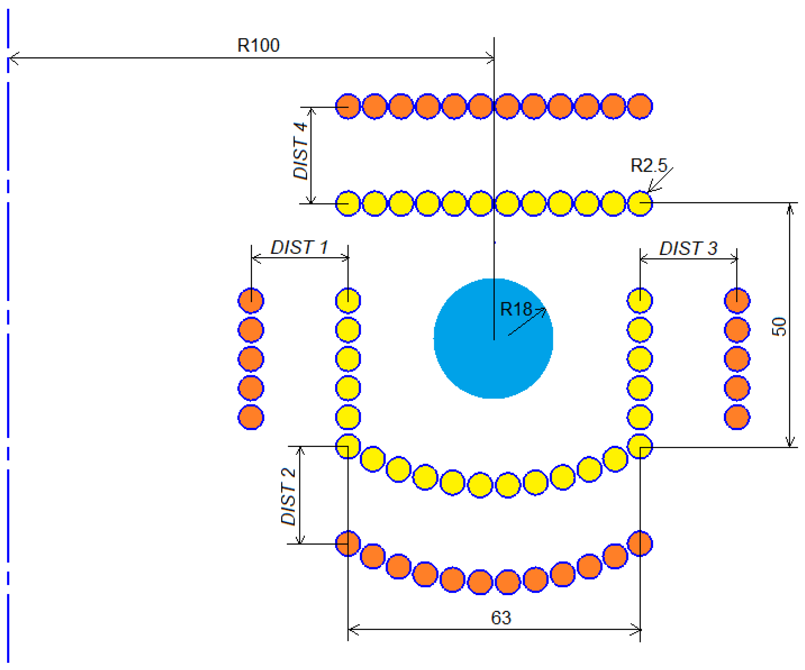
Figure 1. Schematic diagram of a large-scale levitation melting system with four rigid sections. The yellow circles are the base positions of the 4 coil sections. The orange circles are the coil sections shifted by their assigned distances. The blue circle is the melted charge, and the vertical dashed line is the system axis.
Energies 18 04162 g001
Figure 2. Schematic diagram of a large-scale levitation melting system with two coil sections featuring controlled winding envelope. The yellow circles are the base positions of the coil turn, the orange circles are the coil turn shifted by a Δ r radius change, and the blue circle is the charge.
Energies 18 04162 g002
Figure 3. Schematic diagram of an example metal-processing process using the new levitator.
Energies 18 04162 g003
Figure 4. Diagram of a hierarchical optimization system of four coil sections.
Energies 18 04162 g004
Figure 5. The load margin relative to the area of allowable charge presence.
Energies 18 04162 g005
Figure 6. Diagram of a hierarchical optimization system of two coil sections.
Energies 18 04162 g006
Figure 7. Optimal geometry for the variant with four rigid coil sections: horizontal and vertical coordinates [mm] of the centers of the turn cross-sections (orange circles) and the desired position of the centroid of the toroid cross-section (the yellow cross in the blue shape).
Energies 18 04162 g007
Figure 8. Changes in the metal shape and electromagnetic force distribution over time: left column—system with 4 rigid coils, right column—system with 2 coils with envelope-controlled shape. The purple arrows in the first row show the general direction of the Lorentz force.
Energies 18 04162 g008
Figure 9. Time evolution of the cross-section centroid position for a system with 4 rigid coil sections: (a) vertical position, (b) horizontal position.
Energies 18 04162 g009
Figure 10. Distribution of induction (a) and current density (b) for the variant with 4 rigid sections (after 200 s).
Energies 18 04162 g010
Figure 11. Optimal geometry for the the two-coil-section variant with the optimized envelope: horizontal and vertical coordinates [mm] of the centers of the turn cross-sections (orange circles) and the desired position of the centroid of the toroid cross-section (the yellow cross in the blue shape).
Energies 18 04162 g011
Figure 12. Time evolution of the cross-section centroid position for a system with 2 coil sections with the optimized envelope: (a) vertical position, (b) horizontal position.
Energies 18 04162 g012
Figure 13. Distribution of induction (a) and current density (b) for the variant with 2 sections (after 200 s).
Energies 18 04162 g013
Table 1. Properties of molten titanium load.
PropertyValue
Density4110 kg/m3
Electrical conductivity0.56 MS/m
Relative magnetic permeability1.00 μ 0
Dynamic viscosity4.42 mPa s
Surface tension1.56 N/m
Load mass2.6 kg
Table 2. Optimal distances and current for the variant with four rigid coil sections.
DIST 1DIST 2DIST 3DIST 4CURRENT ψ
0.1 [mm]0.1 [mm]7.3 [mm]1.8 [mm]403 [A]4.25 [N]
Table 3. Power supply, Joule heat, and efficiency in the analyzed levitator variants.
Levitator VariantPower Supply [W]Joule Heat Generated in Coil [W]Joule Heat Generated in Charge [W]Efficiency [%]
1: Four coil sections34,56110,05424,50770.91
2: Two coil sections39,55911,55528,00470.79
Table 4. Optimal envelope coefficients and current for the the two-coil-section variant.
a 1 a 2 b 1 CURRENT ψ
0.0004980.0002960.002134439 [A]4.35 [N]
Disclaimer/Publisher’s Note: The statements, opinions and data contained in all publications are solely those of the individual author(s) and contributor(s) and not of MDPI and/or the editor(s). MDPI and/or the editor(s) disclaim responsibility for any injury to people or property resulting from any ideas, methods, instructions or products referred to in the content.