Abstract
The global energy transition and increasingly rigorous legal regulations aimed at climate protection are driving the search for alternative energy sources, including renewable energy sources (RESs) and waste heat. However, the mismatch between supply and demand presents a significant challenge. Thermal energy storage (TES) technologies, particularly mobile thermal energy storage (M-TES), offer a potential solution to address this gap. M-TES can not only balance supply and demand but also facilitate the transportation of heat from the source to the recipient. This paper reviews the current state of M-TES technologies, focusing on their technology readiness level, key operating parameters, and advantages and disadvantages. It is found that M-TES can be based on sensible heat, latent heat, or thermochemical reactions, with the majority of research and projects centered around latent heat storage. Regarding the type of research, significant progress has been made at the laboratory and simulation levels, while real-world implementation remains limited, with few pilot projects and commercially available systems. Despite the limited number of real-world M-TES implementations, currently existing M-TES systems can store up to 5.4 MWh in temperatures ranging from 58 °C to as high as 1300 °C. These findings highlight the potential of the M-TES and offer data for technology selection, simultaneously indicating the research gaps and future research directions.
1. Introduction
1.1. Heating Sector in the World, EU, and Poland in the Light of Energy Transition
Heat is an important energy carrier, which is used in numerous applications. It allows for, among others, maintaining the thermal comfort in buildings and preparing domestic hot water. Also, heat is required in various industries for technological purposes.
Globally, heat accounts for almost half of the final energy consumption, reaching a value of 219 EJ in 2021, of which 53% was used for industrial processes, while 44% was used in buildings for space heating and domestic hot water preparation [1]. What is more, fossil fuels still dominate the infrastructure of heat generation [2]. A similar situation exists in the European Union (EU)—the total gross production of derived heat was approximately 2120 PJ in 2021, with the greatest share coming from renewable energy sources (33.5%), followed by natural and manufactures gases (31.5%), and solid fossil fuels (20.0%) [3]. In turn, the demand for heat in Poland in 2023 was 408 PJ, of which 55.2% was for the industry and construction sector, 35.8% was for households, and the remaining 9.0% was for other consumers [4]. Regarding the structure of fuel consumption for heat generation, coal has been dominating for decades, with a 66.2% share in 2022 [5].
As indicated in the above paragraph, heat has a significant share in the final energy consumption mix. Furthermore, fossil fuels are still dominating the infrastructure of heat generation, both globally and locally, as shown in the example of Poland. Given the global drive for climate neutrality, the heating sector requires a profound energy transition. Considering that the EU has, as discussed in the next paragraph, some of the most stringent regulations on climate neutrality, emissions reductions, and environmental protection in the broadest sense, the remainder of the introduction focuses exclusively on the situation in the EU, especially in Poland.
The European Union (EU) is setting more and more rigorous targets regarding the environment, climate change, and energy. This translates into tightening the directives and other regulations. A recent example of such work is the update to the Energy Efficiency Directive (EED) in October 2023. This directive, first published in 2012, has been revised and now assumes an 11.7% reduction in energy consumption by 2030, which translates into limiting the primary and final energy consumption to 992.5 million tonnes of oil equivalent (Mtoe) and 763 Mtoe, respectively [6]. Moreover, the EED defines an energy-efficient heating system. The heating system can be treated as energy-efficient when it uses at least 50% renewable energy and/or waste heat. The Renewable Energy Directive (RED III) [7], which entered into force in 2023, is the second essential document. It obliges an increase by 2.2 percentage points in the share of renewable energy sources or waste energy for heat production.
To meet the heat demand in Poland, 398 licensed district heating companies with an installed capacity of nearly 53 GW were operating in 2023, while the total length of the district heating network slightly exceeded 22,500 km [8]. The Polish district heating system is one of the biggest, in terms of installed capacity and length, in the European Union, and it accounts for a quarter of the total domestic market for heat, used by about 16 million Poles [5]. The existing district heating system in Poland operates at the supply and return temperatures of 135 °C and 60 °C [9], respectively. As mentioned in the second paragraph, coal has been a dominant fuel for heat generation for decades, with a 66.2% share in 2022 [5]. Therefore, the district heating system has to undergo a deep transition, which is mandated by increasingly stringent legislation.
As shown in the above paragraphs, the district heating sector in Poland requires a profound transition. One of the energy transition measures could be the use of waste heat.
1.2. The Potential of Waste Heat in Poland and the EU
It is estimated that approximately 72% of the energy derived from global primary energy sources is lost to the environment, with industrial sectors alone accounting for 20–50% of energy losses [10]. Industrial waste heat has long been overlooked due to its fragmented nature compared to centralized power generation. However, since the industrial sector accounts for 38% of final energy consumption, its waste heat potential is substantial and warrants thorough investigation [11]. Industrial waste heat (IWH) is defined as the latent and sensible heat released from an industrial process without serving its intended purpose [12]. Waste heat occurs across various temperature ranges, commonly classified as high-grade (>400 °C), medium-grade (100–400 °C), and low-grade (<100 °C) heat [13]. Most industrial waste heat falls within the 100–200 °C range; waste heat exceeding 500 °C is found primarily in the chemical, iron and steel, and non-metallic mineral sectors [14]. The EU’s total waste heat potential is estimated at about 200–300 TWh/year, depending upon the methodology and dataset used [14,15,16,17]. The majority of IWH is within the 100–200 °C range; waste heat below 100 °C is minimal, while significant amounts also exist between 200 and 500 °C [14]. The highest recovery potential is found in the paper, pulp, and printing industries, followed by the non-metallic mineral and iron and steel sectors—industries that generate the largest quantities of waste heat [12].
Waste heat can be used through direct heat recovery, waste heat to power (WHP), and upgrading with high-temperature heat pumps (HTHPs). Direct heat recovery is a method of reusing waste heat directly from its source without converting it into another form of energy. This approach is particularly efficient because it avoids the energy losses associated with transformation and transportation. The recovered heat is often redirected for space heating, domestic hot water preparation, or to support other thermal processes nearby by means of heat recovery from refrigeration systems, compressors, wastewater treatment plants, or other industrial plants and data centers. WHP technologies recover energy from waste heat sources and convert it into electricity: at higher temperatures using conventional steam-based, but at lower temperatures using, for example, Organic Rankine Cycle (ORC) [16], Kalina cycle, the combination of the above [18], and thermoelectric generators (TEGs) [13]. HTHPs make low-temperature heat usable by upgrading it for industrial or heating applications [12]. For Poland, direct heat recovery potential, power production potential from waste heat, and upgraded heat production potential are around 8 TWh/year, 2.5 TWh/year, and below 5 TWh/year, respectively [15].
Another solution for the effective use of waste heat is thermal energy storage (TES), which mitigates mismatches between intermittent industrial waste heat supply and demand, improves capacity factors, reduces start-up and part-load losses, and lowers capital costs by enabling smaller, more efficient system components [19]. In particular, M-TES systems offer a flexible and scalable approach for integrating waste heat into energy systems, making them well-suited for Poland’s diverse industrial landscape and moderate waste heat potential. Given the estimated 15 TWh/year of combined recoverable waste heat, M-TES could play a key role in storing and repurposing a significant share of this energy, potentially contributing several terawatt-hours annually to decarbonizing heat supply in both industrial and district heating applications. Additionally, the future availability and utilization of waste heat in Europe will be increasingly shaped by EU energy policy decisions [10].
1.3. Utilizing Mobile Thermal Energy Storage for Improved Waste Heat Recovery
Waste heat, if effectively recovered, may be utilized either locally or at a remote location. In the latter case, the process of heat utilization typically involves the following stages: heat recovery combined with its storage, transportation to a designated location, and subsequent end-use application. The most commonly used method of heat transport is through district heating networks, which remain the predominant method due to their established infrastructure and operational efficiency [19]. However, increasing attention is being directed toward an alternative solution in the form of a mobile thermal energy storage (M-TES) system, which enables the transport of heat (or cold) by road, rail, or maritime routes. This solution becomes particularly relevant in cases where the construction of a heat pipeline is either technically challenging or economically unjustified. Factors such as high capital and operational expenditures, low spatial density of end-users, or topographical constraints that hinder or elevate the costs of pipeline construction may cause situations when conventional district heating systems are non-viable. Under such conditions, M-TES solutions may offer a more flexible and cost-effective alternative for off-site heat utilization [20].
The conceptual framework for the operation of a mobile thermal energy storage system is illustrated in Figure 1.

Figure 1.
Schematic diagram of mobile thermal energy storage system operation cycle.
According to the presented diagram, the operation cycle of the mobile thermal energy storage consists of the following stages:
- Heat acquisition; M-TES charging;
- Transportation to the recipient;
- Heat utilization; M-TES discharging;
- Return of the M-TES to the heat source for recharging.
The system is defined by two primary location nodes: the charging point and the discharging point—in the context of waste heat utilization, these correspond to the heat recovery site and the heat utilization site, respectively. Both locations must meet specific criteria to ensure the feasibility of M-TES deployment [21]. At the heat recovery site, the continuous and efficient extraction of thermal energy at sufficiently high and stable temperature levels is essential. Furthermore, the cost associated with heat acquisition must be economically justified to ensure overall system viability. On the demand side, the recipient’s thermal requirements must be realistically met by the stored and transported heat. This includes both short-term peak loads and long-term thermal needs. The thermal capacity of the M-TES system, as well as the temperature range of the heat transfer medium, must align with the specific operational requirements of the end-user to ensure efficient and reliable heat delivery. A critical component of the system is the transportation process linking the charging and discharging nodes. In evaluating transport options, particular attention is paid to both economic efficiency and environmental impact. Consequently, various transport modes are considered—such as road, rail, or maritime—along with vehicle technologies that minimize operational costs and reduce emissions [22]. The choice of transport method plays a critical role in the sustainability and scalability of M-TES systems.
2. State-of-the-Art Analysis
2.1. Thermal Energy Storage Technologies in the Mobile Applications
Among the most frequently referenced methods of mobile thermal energy storage are sensible heat storage, latent heat storage, and thermochemical energy storage [23], which are shown in Figure 2.
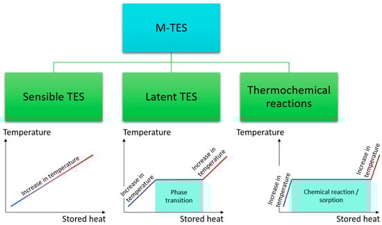
Figure 2.
Classification of M-TES technologies by principle of operation.
Sensible heat storage remains the most commonly employed approach, wherein heat is transferred to the storage medium, resulting in a temperature increase (left graph in Figure 2). The main advantages of this technology are its maturity, low cost, and simplicity, as various easily accessible materials including rock, sand, or water are used in this case. On the other hand, sensible heat storage is characterized by the lower energy storage density, usually not exceeding 0.18 GJ/m3 [24]. In the case of latent heat storage, the thermal energy is stored through a phase change (solid–solid, solid–liquid, liquid–gas, or solid–gas) of the storage material, which theoretically occurs within a defined and constant temperature range (middle graph in Figure 2). However, experimental observations show that minor temperature variations in the material itself can still occur [25]. Phase change materials (PCMs) can store from 2 to 5 times more heat than the sensible heat storage materials [24] but they suffer from numerous problems, including high volume changes during the phase transition (excluding the solid–solid PCMs) [26], flammability, and low thermal conductivity [27,28] (especially organic PCMs), as well as supercooling and phase separation [29] (in the case of salt hydrates). Figure 3 shows a comparison between latent and sensible heat storage.
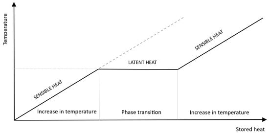
Figure 3.
Latent and sensible heat comparison (own elaboration based on [25]).
Thermochemical heat storage, in turn, stores thermal energy through the heat released during reversible chemical reactions and/or sorption processes involving gases or vapors in solids and liquids (right graph in Figure 2). Among the three main thermal energy storage technologies, thermochemical heat storage offers the highest energy storage density. However, despite its potential, thermochemical heat storage remains less developed due to its greater complexity [30,31]. This method is applicable when the reaction products can be stored separately and the stored thermal energy can be released upon the occurrence of the reverse reaction. Heat is absorbed during the endothermic reaction and released during the exothermic reaction [32]. Figure 4 presents the classification of thermochemical heat storage methods.
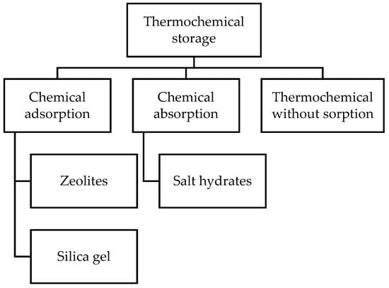
Figure 4.
Thermochemical storage classification (own elaboration based on [33,34].
The indicated technologies have been compared in terms of temperature ranges, thermal energy storage capacities, heat retention time, and technology readiness [35,36]. A summary of the main characteristics of discussed technologies is presented in Table 1.

Table 1.
Thermal energy storage technologies used in mobile applications and their typical properties; h—hours, d—days, w—weeks, m—months [35,36].
The following state-of-the-art analysis presents solutions described in the scientific literature, as well as market-based technologies and pilot projects identified during the review. The solutions are classified according to three distinct thermal energy storage technologies: sensible TES, thermochemical reactions, and latent TES.
2.2. Bibliometric Analysis
According to the Google Scholar database, which was searched on 26 June 2025 for the following search string: “mobile thermal energy storage” OR “mobilized thermal energy storage”, the first scientific publication on M-TES technology was published in 2005. Then, up to 2015, the annual number of publications on M-TES did not exceed 10, as shown in Figure 5. M-TES has been gaining more and more attention since 2015 (24 publications), with a breakthrough in 2021, when the number of publications was 52.

Figure 5.
Number of publications related to M-TES from 2005 to 2025.
The increased interest in M-TES technology can be correlated to the introduction of energy efficiency and climate neutrality regulations. At the EU level, examples of such regulations include the Energy Efficiency Directive (EED), the first version of which was adopted in 2012 and an updated version in 2023, which targets an 11.7% reduction in energy consumption by 2030 [6]. A second example is the Renewable Energy Directive (RED III) (2023) [7], which obliges an increase by 2.2 percentage points in the share of renewable energy sources or waste energy for heat production. Examples of countries outside the EU that are also heavily researching M-TES are Japan and China. These countries are also enacting various regulations, contributing to the resurgence of interest in M-TES technology. An example of such regulations is the Green Transformation (GX) Policy, which is designed to promote the decarbonization of the energy sector and went into effect in Japan in 2023 [37]. In China, on the other hand, the Energy Development Strategic Action Plan (2014–2020), Energy Technology Revolution Innovation Action Plan (2016–2030), or Guiding Opinions on Promoting the Development of Energy Storage Industry and Technology can be cited as examples [38].
2.3. M-TES—Sensible Thermal Energy Storage
The use of sensible heat is a well-established and widely recognized method of thermal energy storage. As early as the 1980s, its application in mobile systems was explored through the Altvater Mobile Heat Transport System [39]. The technology employed oil as the heat storage medium. Although the development was initially discontinued, it was resumed in 2006. The first pilot-scale project aimed to recover waste heat from the Oberland-Glas glassworks, store it in thermal oil at a temperature of 320 °C, and transport it by truck over a distance of 38 km for utilization at the Neutrauchburg Clinic.
Among the currently available M-TES solutions, there exists an approach based on sensible heat storage. Such a system is offered by the German company Kraftblock [40]. The storage unit is charged using heat derived from sources such as industrial waste heat or renewable energy. The thermal energy is stored in a transportable container, which can be delivered by truck, train, or ship. The system employs a specially developed granular material characterized by high thermal conductivity and a high specific heat capacity. As a result, a single transportable container can store up to 4 MWh of thermal energy. This solution is particularly recommended for locations where access to district heating networks is limited—for instance, due to challenging terrain or low population density, which could significantly increase the cost of network expansion.
2.4. M-TES—Thermochemical Reactions
Thermochemical TES methods demonstrate significant potential in terms of specific thermal energy storage capacity. The energy density achievable in thermochemical systems exceeds the values typical for other heat storage methods, particularly sensible heat storage, making them especially attractive for applications requiring compact and efficient solutions, such as mobile thermal energy storage systems. An additional advantage is their ability to store energy over long periods with minimal thermal losses, which further highlights their potential in the context of future sustainable energy systems. The majority of solutions utilizing this technology remain in the development stage [35,36]. The following section outlines representative examples identified in current research.
Narwal et al. [41] conducted laboratory-scale experimental research on the potential application of zeolites in M-TES systems. Under specific, predefined conditions, a thermal energy storage density exceeding 110 kWhth/m3 was achieved. The study confirmed the feasibility of a process in which the heat stored in zeolites during the charging phase can be retained separately from the discharging unit. Additionally, the thermal storage density was evaluated for zeolite loaded into packed, transportable tubes made of stainless steel mesh, reaching a value of 30.6 kWhth/m3.
Krönauer et al. [42] presented a one-year research work of a demonstration installation utilizing extraction steam from a waste incineration plant to charge an M-TES system with hot air at 130 °C. The stored heat was used in an industrial drying process. Thermal energy was transported over a distance of 7 km from the charging point. The storage unit contained 14 tons of zeolite and it was possible to achieve a storage capacity of 2.3 MWh. This enabled a reduction of 616 kg in carbon dioxide emissions per cycle. However, the authors noted that improper heat distribution within the zeolite bed prevented the system from achieving the desired output power. In turn, Wang et al. [43] focused on assessing the potential of using an M-TES system in the decarbonization of district heating networks. The analysis was carried out for the Netherlands conditions. The simulations were based on a combination of experimental data and theoretical assumptions. The M-TES system is intended to supply waste heat from various sources to an urban district heating network. The authors demonstrated that, under optimal operational scenarios and strategies, the use of M-TES could reduce carbon dioxide emissions from approximately 60–70 kgCO2/GJ (in systems without M-TES) to around 13 kgCO2/GJ, which gives reduction up to 80%. While the study identified several advantages of the M-TES approach, it also pointed to challenges, particularly those related to heat transport logistics.
Another identified approach, apart from laboratory or demonstration research, analyzes the application of zeolites in M-TES systems using computational fluid dynamics (CFD) simulations, as presented by Kang et al. [44]. The research focused on a thermal storage core utilizing the adsorption process. The authors conducted simulations and analyses of heat and mass transfer in a zeolite–water thermal accumulator. The study identified several key factors significantly influencing the process performance: the inlet velocity of dry air (during the adsorption process), inlet air temperature, moisture content of the inlet air, and inlet steam temperature. The final parameter analyzed was the water content in the heat exchanger vessel, which, within the examined range, was shown to have a negligible effect on the process.
A distinctive approach was presented by Nagamani et al. [45]. The study reported the results of a performance evaluation of a thermochemical mobile heat storage and utilization system, obtained through the development of an analytical model. The model incorporated performance parameters such as the energy efficiency ratio, charge–discharge efficiency, coefficient of performance, and energetic and exergetic efficiency, as well as the exergy destruction rate.
In the study [46], Fujii presented the results of the numerical modeling and environmental assessment of an M-TES system based on water vapor adsorption and desorption in zeolite for the recovery and storage of industrial waste heat. The study evaluated the system’s performance and resource use, as well as the impact of various parameters on greenhouse gas emissions. Additionally, key areas for the environmental optimization of such systems were identified.
Pavangat et al. [47] present a techno-economic analysis of a thermochemical M-TES system utilizing lithium chloride. The feasibility of using the system for the recovery of industrial waste heat from a steel plant is evaluated. The potential application of the system for powering a building cooling network on a university campus in India is also assessed. An additional and important aspect of the analysis is the comparison of results for different transportation methods: diesel, hybrid, and solar-powered trucks.
2.5. M-TES—Latent Thermal Energy Storage
The literature review on mobile thermal energy storage indicates a strong focus on methods utilizing latent heat. Numerous solutions are described across the reviewed sources, ranging from early-stage laboratory concepts to commercially available systems. This interest is driven by the favorable properties of phase change materials (PCMs), including high energy storage density, a consistent phase transition temperature, and the ability to undergo multiple thermal cycles with minimal performance loss. These properties are especially valuable in mobile applications, where space and weight limitations play a crucial role. The next section provides an overview of relevant examples identified in the literature.
Nomura et al. [48] presented the development and evaluation of a PCM-based M-TES system that utilizes high-temperature PCMs (NaOH with a solid–solid transition temperature of 293 °C and a melting temperature of 320 °C). The objective was to assess whether waste heat from industrial processes—specifically from steel production—could be effectively collected, transported, and reused in the chemical industry, particularly in the heating of a BTX (benzene, toluene, xylene) distillation tower. To evaluate this concept, the authors compared the system’s performance with traditional heat supply approaches and an M-TES system using sensible heat. Key factors such as energy use, the degradation of energy quality (exergy loss), and greenhouse gas emissions were assessed through thermodynamic calculations. The phase change material considered in the system exhibits transitions at high temperatures, making it suitable for the recovery of industrial waste heat. The results confirmed that this approach can significantly reduce energy consumption and emissions while delivering more thermal energy than conventional methods. Other work focused on industrial waste heat recovery is presented by Yang et al. [49] and includes analysis for UK location conditions. The paper presents a model-driven design and operation evaluation M-TES system, consisting of a container filled with composite PCM bricks (Figure 6). The system employs composite phase change materials and utilizes air as the heat transfer medium for both the charging and discharging processes. Through validation by experiments as well as 2D and 3D computational fluid dynamics models, the study investigates key performance aspects such as heat storage capacity, temperature distribution, energy transfer efficiency, and charging/discharging dynamics. The results confirm the system’s potential to effectively store and release thermal energy over extended periods, maintaining favorable temperature conditions and minimal pressure drops. A pilot version of the device was also built and tested, revealing areas for practical improvement, including insulation quality, component fit, and heat transfer optimization. The authors highlight the feasibility of using the M-TES system to connect industrial heat recovery with domestic energy supply, contributing to decarbonization efforts in thermal processing sectors.
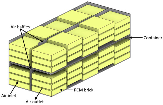
Figure 6.
A sketch of the M-TES system proposed by Yang et al. [49].
Another study showing the field testing of an M-TES system, presented by Kuta [50]. Research focuses on the development and testing of an M-TES system designed to store and deliver heat to single-family residential buildings using geothermal energy as a heat source. The main goal was to assess the feasibility of using a PCM-based M-TES system, charged with geothermal heat, for decentralized heating applications in Poland. Temperature data collected at multiple points inside the tank allowed the researchers to evaluate the system’s performance during both the charging and discharging phases. The system demonstrated stable operation, effective heat delivery without user discomfort, and a heat storage capacity of approximately 45 kWh. The study confirmed the technical feasibility of geothermal-powered M-TES systems for residential heating and identified areas for further improvement, particularly in PCM optimization and exchanger design, to support wider commercial use. A new approach to the use of industrial waste heat with the cooperation of the M-TES system was proposed by Ingelaere et al. [51]. The paper explores a strategy for enhancing the efficiency of ground-source heat pump systems by intermittently recharging ground heat exchangers with industrial waste heat. Using an M-TES unit, heat is transported from industrial sites and injected into the ground to raise subsurface temperatures during the heating season. TRNSYS simulations were conducted for a residential setting in a cold climate to assess how varying the frequency and duration of heat injections impacts system performance. The results show that periodic recharging can significantly reduce the required depth of boreholes (by nearly half) and slightly lower the energy consumption of the heat pump. Authors demonstrated the potential of integrating M-TES waste heat recovery into geothermal heating systems as a way to improve efficiency and reduce installation costs.
Li et al. [52] focused on an economic analysis of the M-TES system, dedicated to distributed heat users. The influence of various factors on the cost of heat delivery was examined. It was shown that the cost is largely dependent on the transport distance (inversely proportional relationship) and the heat demand (directly proportional relationship). The sensitivity analysis highlighted the significant role of the PCM price, which had a much greater impact than other parameters. The authors emphasized the necessity of achieving a minimum cost level for given values of other parameters and provided the corresponding relationships. Additionally, the study presented a comparison of the system with conventional solutions such as pellet boilers and heat pumps, demonstrating that, under certain conditions, the M-TES system can be competitive.
Wang et al. [53] presented the results of experimental work conducted using a test rig that includes both direct and indirect contact systems. The analysis enabled a comparison of the performance of these two systems and provided a better understanding of the charging and discharging processes. The experiments were carried out using erythritol (phase change heat and temperature: 330 kJ/kg; 118 °C). The authors suggest that the use of a direct contact storage system may enable shorter charging and discharging times compared to the indirect system. In the direct contact system, a significant difference was observed between the charging and discharging times. During the charging phase, limitations were observed due to the blockage of thermal oil flow caused by unmelted PCM. In contrast, the indirect contact system showed similar charging and discharging times. No significant impact of the heat transfer fluid flow rate on the process was observed in the indirect contact system. However, the authors expect a significant influence of this parameter in the case of the direct contact system. Guo et al. [54] build upon the authors’ previous research work. During experimental investigations, issues related to the melting process of the PCM during the charging phase of the storage system were identified, particularly regarding the charging time. As a result, a two-dimensional numerical simulation model was developed in ANSYS FLUENT to better understand the process and minimize problems such as the blockage of thermal oil flow, which limits process efficiency. The modeling work was validated through experimental studies. Various methods to improve process efficiency were analyzed, including the creation of additional flow channels, changes in thermal oil flow rate, and the introduction of wall heating in the storage unit. The results showed a reduction in charging time by up to 52%. In another study [55], Guo et al. addressed the issue of the flow blockage of the heat transfer fluid in a direct M-TES system using erythritol as the working material for thermal energy storage and thermal oil as the heat transfer fluid. In their experimental work, they tested the effects of using additional electric heaters to create channels in the solidified PCM. It was shown that this solution accelerates the charging process during its early and middle stages compared to systems without additional heaters. However, in the later stage of charging, this method is no longer effective, as the channels disappear with the progression of PCM melting. In the test bench experiments, the energy consumption associated with the use of heaters accounted for 5% of the stored energy. Nevertheless, the authors noted that, in a full-scale system, this share would be significantly lower. He et al. [56] presented a new approach to the research discussed in previous works, including [55] by incorporating a double tubular structure at both the inlet and outlet of the storage tank. The paper focuses on the development and performance evaluation of an enhanced thermal energy storage system using direct contact between PCM and a heat transfer fluid, dedicated for M-TES system application. The primary objective was to improve heat charging and discharging rates by modifying the container design with a U-shaped tube and to compare the system’s performance in both direct-contact and indirect-contact configurations. In the experiment, erythritol was used as the PCM, and thermal oil served as the working fluid. The study analyzed phase change dynamics, heat transfer behavior, and the influence of flow rates on system performance. Results demonstrated that the direct-contact configuration significantly outperformed the indirect one, especially in terms of faster heat transfer and shorter charging/discharging times. The formation of flow channels within the solid PCM was facilitated by the high thermal conductivity of the U-tube, enhancing melting efficiency at the initial charging stage. The research also highlighted how fluid motion and structural design affect phase change behavior. Authors showed that, in contrast to the indirect-contact system—where heat transfer occurs through the tube wall—the direct-contact system enabled more efficient thermal exchange due to the direct mixing of PCM and heat transfer fluid (HTF). The paper concludes that further performance improvements could be achieved through flow field optimization and an analysis of long-term operation under cyclic thermal loads.
In yet another study [57], Guo et al. presented the performance results of a thermal energy storage system based on the use of a shell-and-tube heat exchanger (Figure 7). The storage system is intended for mobile applications. A numerical analysis of the phase change process was carried out and supported by experimental results. To assess the potential for improving the efficiency of the phase change process, various enhancement methods were analyzed, including modifications to the heat exchanger design and the use of carbon additives. The study showed that optimal solutions may include the addition of 10% carbon material (expanded graphite), the use of heat exchanger tubes with a diameter of 22 mm, or the implementation of fins with a surface area of 0.468 m2. Importantly, the simultaneous application of all three methods can reduce the charging and discharging time by 74% and 67%, respectively.
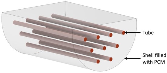
Figure 7.
A sketch of the M-TES system based on the shell-and-tube heat exchanger proposed by Guo et al. [57].
Also, in their study [58], Demirkıran et al. conducted a numerical investigation. The aim of the work was to analyze the melting behavior of phase change materials in a shell-and-tube thermal energy storage unit designed for the M-TES system. The primary objective was to enhance heat transfer efficiency by optimizing fin configurations without increasing the total volume of fin material, thereby maintaining low system costs. The research involved three different fin quantities (two, four, and six) and two geometrical types (straight and branched). Each configuration was evaluated by positioning the fins in different sections of the PCM domain, particularly in the upper and lower regions of the HTF tube. For configurations with four fins, the influence of varying fin lengths was also assessed. Results revealed that straight fins outperformed branched designs in terms of melting efficiency, and positioning fins at the top of the domain—despite contrary assumptions in the previous literature—led to significantly improved thermal performance. Among all configurations, the system with four fins of varying lengths achieved the most favorable results, showing the highest melting ratio and efficiency gain without additional material use. Furthermore, it was observed that increasing the number of fins beyond four did not enhance, and in some cases even reduced, the melting rate due to inhibited convection and reduced spacing between fins. A numerical model was also used by Liu et al. [59], to enhance the melting efficiency of PCM in latent thermal energy storage systems, by developing a novel ladder-shaped fin geometry. Eight fin configurations were designed, all using the same amount of fin material, and grouped based on their orientation relative to the vertical axis. The goal was to investigate how fin geometry and placement affect the melting behavior and heat transfer performance. Numerical simulations were carried out using the enthalpy–porosity method to model the transient melting process, taking into account the temperature distribution and natural convection in the liquid phase. The model was validated against experimental data from the literature. The results showed that the ladder-shaped fins significantly outperformed traditional straight fins in accelerating the melting process, with reductions in total melting time of over 50% in certain cases. Fin orientation played a critical role: vertical and horizontal arrangements led to shorter melting times compared to diagonal placement. It was also found that the geometry of the bottom fins had a particularly strong impact on system performance, as larger bottom fins enhanced heat transfer and reduced overall melting duration. The authors demonstrated the potential of the proposed fin structure for improving thermal energy storage systems and suggested the possibility of applications in M-TES systems. A different type of M-TES unit structure was numerically analyzed by Guo et al. [60]. The study focuses on optimizing an M-TES system that uses plate-type phase change units to store and transport industrial waste heat. Through detailed computational simulations, the authors investigated how system performance is influenced by the orientation of the thermal storage unit, the direction of heat transfer fluid flow, and the temperature difference between the heat transfer fluid and the phase change material. The findings highlighted that a horizontal placement of the storage plates, a top-down flow configuration, and a greater temperature difference between HTF and PCM significantly enhance the efficiency of heat charging. The authors showed that the development of more effective M-TES systems can help to balance spatial and temporal mismatches in energy availability, particularly in the context of China’s growing energy demands and waste heat potential. Kang et al. [61] presented a numerical analysis of a different type of heat exchanger—a capsule-based design. The study explores how to enhance the performance of a capsule-based M-TES system by analyzing the influence of design and operating parameters on the phase change material melting process. Using numerical simulations, the study evaluates how the positioning of inlets and outlets, the number and arrangement of PCM capsules, and their geometric shapes affect heat transfer efficiency. The findings show that specific configurations, such as square-shaped capsules, optimized inlet–outlet placement, and orderly capsule arrangements, significantly improve the PCM melting rate and overall charging performance. The authors also provide design guidelines for improving the efficiency and thermal stability of compact, M-TES systems.
In a further study [62], Guo et al. conducted an economic assessment of an M-TES solution utilizing a direct-contact thermal energy storage system. The analyzed solution is intended for small and medium-sized heat users in China. The evaluation included an analysis of the heat delivery logistics using two containers delivered in rotation. Results were compared for different numbers of daily trips (two, three, four, six, and eight trips). It was shown that, among the analyzed scenarios, the most favorable one involved six transports per day. In this case, the return on investment was estimated to be 2–5 years, depending on the cost level of the waste heat. In the study [63], Guo et al. also addressed the logistics of heat delivery using the M-TES system, evaluating its potential as an alternative heat supply solution for dispersed users in China. Alongside the economic analysis, the study assessed the feasibility of integrating such systems with existing building heating infrastructure. It was shown that M-TES can be successfully combined with heating systems based on fan coil units as well as underfloor heating. For the analyzed scenarios, the recommended configuration is to use two containers transported four times per day. Under these conditions, the payback period was estimated at 10 years. An economic analysis of the application of the M-TES system for small-scale consumers (individual users) was also presented by Matuszewska et al. [64]. The study considered the implementation of the system in Poland, using geothermal energy as the heat source for charging the M-TES and employing a phase change material (PCM) characterized by a melting temperature of 70 °C and a latent heat of 250 kJ/kg. The results confirmed the cost-effectiveness of the system for three different levels of annual heat demand: 5000, 15,000, and 25,000 kWh. For each of these demand levels, the corresponding heat price and maximum transport distance were estimated respectively as 0.21 EUR/kWh and 0.5 km, 0.11 EUR/kWh and 0.5 km, and 0.085 EUR/kWh and 0.5 km. Deckert et al. [65] presented the results of prototype research on a modular M-TES system. An economic and technical analysis was conducted, assuming the use of waste heat. Particular attention was given to minimizing the system’s charging and discharging times, with tests carried out in this area. To determine the optimal parameters, various aspects were tested, including the flow rate and temperature of the heat transfer fluid, input and output power, and the geometry of the heat exchanger. The study demonstrated the practical and economically justified feasibility of using this type of system. The importance of factors such as storage capacity and usage strategy was emphasized. The tests also examined the use of carbon-based additives to improve the thermal conductivity of the PCM, while also highlighting the cost implications of these additives. Chiu et al. [66] presented an economic, but also technical and environmental, analysis of an M-TES system utilizing industrial waste heat for use in a low-temperature district heating network. The technological part focused on PCM, the storage design, and the operating system. The economic analysis was conducted based on the assumption of system operation in Sweden and transport over a distance of 48 km, taking into account various transport methods and operational strategies. The environmental analysis considered CO2 emissions for different transport methods, while assuming zero emissions for the waste heat. The results demonstrated the potential of the M-TES system for the intended application, provided that appropriate operational strategies are applied. Similarly, from an environmental perspective, the solution shows significant potential compared to conventional systems. In their study [67], Shehadeh et al. conducted an analysis on the potential integration of an M-TES system into a district heating network was conducted. Also, in this study, the focus was placed on the economic, technical, and environmental aspects of the project. The analysis was carried out for the city of Surrey in British Columbia, Canada, assuming that the M-TES system would be powered by industrial waste heat. The study examined the cost of emission reduction by comparing the M-TES solution with the existing approach (gas boilers and a vertical geothermal exchange system). The authors highlighted that, for such systems, ensuring sufficient energy density is essential, along with considering appropriate transport distance and method. It was indicated that, in order for the system to be competitive, a minimum energy density of 0.4 MJ/kg is required. Acceptable transport distances were estimated at 15–50 km when using a truck powered by renewable natural gas (RNG) or an electric truck, and no more than 30 km when using a diesel-powered truck.
Zhang et al. [68] proposed an M-TES system that incorporates spherical capsules containing PCM modified with copper additives (99.6% erythritol + 0.4% copper nanoparticles), with a latent heat of 362.2 kJ/kg. To analyze the phase change process, both experimental and theoretical studies were conducted. A mathematical model was developed to investigate the effect of the capsule radius on the process. The influence of various ambient temperatures was also analyzed. Additionally, due to the specific design of the thermal storage unit, the theoretical model focused on the effects of rotation during the transport. A good compatibility was achieved between the theoretical and experimental results.
In their study [69], Wang et al. presented experimental results of a thermal energy storage system utilizing phase change materials, designed for the recovery of industrial waste heat or the use of renewable heat sources in M-TES applications. The system was tested under conditions simulating a domestic hot water supply setup. Sodium acetate trihydrate was used as the PCM, enclosed in tubular containers. The experiments revealed challenges related to natural convection, which caused the discharging phase to take longer than the charging phase. Additionally, an uneven melting of the PCM within the tubes was observed. Based on the tested conditions, the system efficiency was estimated at 79.4%.
Two studies [70,71] focus on the application of M-TES systems to improve energy efficiency in large-scale buildings, using a university campus in Tripoli, Lebanon, as a case study. The research explores the use of waste heat from a power plant to cover the heating, cooling, and domestic hot water demands of the campus. Simulations using Simulink-MATLAB were conducted to analyze the charging, self-discharging, and discharging phases of the M-TES system. The authors assumed the application of erythritol and Therminol55 as a PCM and heat transfer fluid. Simulations findings show that increasing the HTF flow rate reduces charging time and improves system efficiency, while larger-scale implementations lead to lower heat costs. Economic evaluations demonstrate that the system is cost-effective, with a relatively short payback period. Authors highlighted in both studies that M-TES can be a sustainable and efficient thermal energy storage solution with promising applications in energy systems utilizing waste heat. Another work focused on a case study in Lebanon is [72]. In this case, Kesserwani et al. focus on technical, economic, and environmental aspects. The authors evaluate the technical, economic, and environmental feasibility of M-TES systems as an alternative to conventional heating solutions, particularly for small- and medium-sized heat consumers. They examine how PCM-based M-TES, powered by industrial waste heat, can integrate with existing heating infrastructures like underfloor heating and fan coil systems. Through simulations of different operating scenarios, including container configurations and transportation cycles, the study identifies strategies that optimize cost-effectiveness and environmental performance. The optimal setup (application of two containers and three daily transportation cycles) shows a favorable payback period and significant reductions in CO2 emissions. The research underscores the potential of M-TES to support sustainable development goals by reducing reliance on fossil fuels, lowering emissions, and promoting innovative energy storage solutions. The authors are planning future work on assessing long-term operational challenges and conducting life cycle assessments to further validate the system’s sustainability.
A significant amount of work focuses on the application of M-TES for the purpose of storing and transporting heat. In the case of work [73], Hunt et al. explore a novel approach to sustainable urban cooling by integrating seawater air conditioning with an M-TES system. This addresses the challenge of high investment costs typically associated with district cooling systems and proposes a solution that enables efficient cooling delivery to inland areas, even up to 10 km from the coast. The authors showed that, by using cold seawater to charge PCM units, which are then transported to end-users, it is possible to significantly lower the costs of the energy and enhance cooling performance. This case study, typical for island regions, showed that applying the M-TES system can support systems’ energy efficiency and cost competitiveness compared to conventional air conditioning. The authors highlighted the system’s potential to reduce CO2 emissions and support climate goals, especially in tropical and subtropical regions. The authors also showed future research directions to validate environmental and economic performance through experimental data and life cycle assessments.
3. Discussion
A review of the current state of the art in the field of mobile thermal energy storage systems indicates a strong focus on using these systems to enhance the recovery and utilization of waste heat, particularly from industrial processes. In some cases, renewable energy sources are also being considered as heat supply sources for M-TES systems. The primary target users are typically decentralized small- and medium-scale consumers. There is a growing interest in integrating M-TES with district heating networks, as well as exploring its potential for large-scale industrial applications. Beyond transporting heat, M-TES technologies are also being examined for their ability to store and deliver cooling.
The technologies employed in M-TES systems include sensible heat storage, latent heat storage, and thermochemical processes. Our literature analysis shows that a significant portion of research is devoted to latent heat solutions, particularly those involving phase change materials.
Identified studies on M-TES systems cover a wide range of areas. Works addressing this topic consider not only technological but also economic, environmental, and legal aspects.
A significant number of works are dedicated to technical issues, such as the system design, proper selection of M-TES components, organization of charging and discharging operations, transportation logistics, and adaptation of M-TES parameters to match both the heat source capabilities and the user’s requirements. In the context of PCM-based systems, many works focus on simulations and experimental studies exploring the influence of heat exchanger design on the efficiency of thermal exchange processes. In the case of direct contact systems, attention is given to enhancing heat transfer between the heat transfer fluid and the PCM, as well as overcoming process-related challenges. Erythritol is the most commonly proposed PCM for mobile applications, used in both direct- and indirect-contact systems. In the case of sensible heat storage, identified solutions include systems using both liquid and solid storage media. For thermochemical storage, the use of zeolites is most commonly considered.
Studies focused on economic aspects pay close attention to the factors that most significantly impact M-TES systems’ profitability. These include, above all, capital and operational expenditures, such as the cost of system components, the cost of heat supplied to the system, and transportation distance and method (which directly affect logistics expenses), as well as the energy storage density achievable within the system and the heat demand levels on the user side.
Environmental assessments largely focus on the method and distance of transport, as different transport options can result in varying levels of emissions. At the same time, such studies consider the environmental benefits of utilizing heat that would otherwise go to waste under standard conditions. Some authors also emphasize the need to include data on the process of generating the recovered waste heat in future analyses.
The legal issues discussed in the analyses primarily relate to compliance with transport regulations in force in a given region, particularly concerning limitations on the permissible transport weight and other relevant legal requirements.
M-TES remains a relatively novel concept, with a limited number of research studies and practical implementations to date. This indicates both the emerging nature of the field and the current lack of widely accessible, fully commercialized solutions. However, it is important to emphasize that literature reviews reveal a growing interest in this topic. This increasing attention is reflected in the rising number of scientific publications addressing various aspects of mobile thermal energy storage. The summary of the state-of-the-art analysis is presented in Table 2.
Table 2.
Identified examples of research work and work at various stages of implementation in the M-TES area. IWH—industrial waste heat; RE—renewable energy; PP—pilot project; C—commercially available; S—simulation; AM—analytical model; MM—mathematical model; L—laboratory experiment; En—environmental analysis; Ec—economic analysis; Tech—technical analysis; Th—theoretical analysis.
The state-of-the-art review in the field of mobile thermal energy storage systems revealed a number of research gaps and opportunities to be addressed:
- There is a limited number of commercially available solutions. M-TES is an emerging technology. Only a few commercial offerings have been identified, yet the technology’s potential and opportunities for improvement and market uptake are clear. Grant support and the development of appropriate regulations could further stimulate the M-TES market.
- Thermal energy storage density is limited. Given the constraints on mass and volume in M-TES applications, there is a need to maximize the amount of heat stored per unit mass and volume.
- Heat-exchange rate is limited. To enhance system utilization, charging and discharging rates must be maximized. For PCM-based systems, this calls for improved PCM thermal conductivity or more efficient heat exchanger designs.
- There are important technical transport limitations. There is a lack of standardized transport solutions and effective distance is severely constrained. The development of lighter tank structures and better thermal insulation to reduce weight, size, and cost is required.
- There are important scalability and integration constraints. Solutions capable of flexible scaling to match the needs of both heat suppliers and end users are missing. Work is needed on turnkey systems that can be rapidly deployed in district heating networks, in individual buildings, and with various heat sources (waste heat, renewables).
- Economic aspects and business models need to be better analyzed. Data on capital and operating costs are scarce, and comprehensive profitability analyses are lacking. Pilot projects exploring diverse business and operational models, as well as leveraging low-cost waste heat, are necessary.
- Life-cycle assessments (LCA) for complete systems and individual components (especially PCMs), as well as emissions data, remain limited. Comparative studies of different storage media and transport methods are needed.
- Due to the novelty of the technology, unified regulations and procedures for M-TES approval and road transport are absent. The development of industry standards and streamlined certification pathways is essential.
- Advanced digital tools and models for scheduling and logistics optimization are lacking. The application of digital twins and predictive algorithms could greatly enhance system management.
- The awareness of M-TES benefits among potential users is low. Outreach campaigns, informational programs, and training for district heating operators will be critical to foster adoption.
4. Conclusions
In this paper, a state-of-the-art analysis of M-TES was carried out. The diverse range of M-TES technologies, based on sensible heat, latent heat, and thermochemical reactions, was reviewed. The majority of current research and practical applications focus on latent heat storage, which shows great potential due to its relatively high energy density. Despite the advances in lab-scale experiments and simulations, the deployment of M-TES in real-world, commercially available systems remains limited. Pilot or commercially available systems can store up to 5.4 MWh, with temperature ranges extending from 58 °C to 1300 °C, indicating the versatility of M-TES in varying operational conditions.
In the context of waste heat and energy transformation, M-TES plays a pivotal role in facilitating the recovery, storage, and transportation of otherwise wasted thermal energy. Industrial processes, such as chemical, iron and steel, paper, and pulp and printing industries, produce substantial amounts of waste heat. Integrating M-TES technology into these sectors allows for capturing, transporting, and using this heat that otherwise would be underutilized. Therefore, the application of M-TES holds significant potential in enhancing the efficiency of energy systems, supporting the decarbonization of industries, and reducing reliance on fossil fuels.
Further research in M-TES technology should be focused on large-scale systems and reducing the costs of this technology, which is essential to fully unlock its potential and spread its use.
To summarize, M-TES represents a critical tool in the future energy landscape, offering not just a method for thermal energy storage but also a mechanism for integrating waste heat recovery and advancing global energy transformation.
Author Contributions
Conceptualization, M.K.; methodology, M.K.; investigation, M.K., E.R. and A.M.-M.; writing—original draft preparation, M.K., E.R. and A.M.-M.; writing—review and editing, M.K., E.R., A.M.-M. and A.G.; visualization, M.K.; supervision, A.G.; project administration, A.G.; funding acquisition, A.G. All authors have read and agreed to the published version of the manuscript.
Funding
This research was mainly supported by The National Centre for Research and Development, Poland—project “Opracowanie mobilnego magazynu ciepła pozwalającego na wykorzystanie ciepła odpadowego dla spółki PTEP” Nowe Technologie w Zakresie Energii II (NTE-II/0004/2022), and partially supported by the Ministry of Science and Higher Education, Poland, grant AGH number 16.16.210.476.
Data Availability Statement
No new data were created in this study. Data sharing is not applicable to this article.
Conflicts of Interest
The authors declare no conflicts of interest.
Abbreviations
The following abbreviations are used in this manuscript:
| BTX | benzene, toluene, xylene |
| CFD | computational fluid dynamics |
| EED | Energy Efficiency Directive |
| EU | European Union |
| HTF | heat transfer fluid |
| HTHP | high-temperature heat pump |
| IWH | industrial waste heat |
| M-TES | mobile thermal energy storage |
| ORC | Organic Rankine Cycle |
| PCM | phase change material |
| RE | renewable energy |
| RED | Renewable Energy Directive |
| RNG | renewable natural gas |
| TEG | thermoelectric generator |
| TES | thermal energy storage |
| WHP | waste heat to power |
References
- IEA Renewable Heat. Available online: https://www.iea.org/reports/renewables-2022/renewable-heat (accessed on 7 July 2025).
- IEA Heating. Available online: https://www.iea.org/energy-system/buildings/heating (accessed on 7 July 2025).
- Eurostat Electricity and Heat Statistics. Available online: https://ec.europa.eu/eurostat/statistics-explained/index.php?title=Electricity_and_heat_statistics#Derived_heat_production (accessed on 7 July 2025).
- Zużycie Paliw i Nośników Energii w 2023 r.; Warszawa, 2024. Available online: https://stat.gov.pl/obszary-tematyczne/srodowisko-energia/energia/zuzycie-paliw-i-nosnikow-energii-w-2023-roku,6,18.html (accessed on 7 July 2025).
- Szczerbowski, R. Stan obecny i przyszłość ciepłownictwa w Polsce. Zesz. Nauk. Inst. Gospod. Surowcami Miner. Energią Pol. Akad. Nauk 2024, 112, 53–62. Available online: https://bibliotekanauki.pl/articles/59112299 (accessed on 7 July 2025).
- Energy Efficiency Targets. Available online: https://energy.ec.europa.eu/topics/energy-efficiency/energy-efficiency-targets-directive-and-rules/energy-efficiency-targets_en (accessed on 24 March 2025).
- Directive (EU) 2023/2413 of the European Parliament and of the Council of 18 October 2023 Amending Directive (EU) 2018/2001, Regulation (EU) 2018/1999 and Directive 98/70/EC as Regards the Promotion of Energy from Renewable Sources, and Repealing Council. Available online: https://eur-lex.europa.eu/eli/dir/2023/2413/oj/eng (accessed on 7 July 2025).
- Energetyka Cieplna w Liczbach; Warszawa, 2025. Available online: https://www.ure.gov.pl/pl/cieplo/energetyka-cieplna-w-l/12424,2023.html (accessed on 7 July 2025).
- Tobolczyk, G. Szanse i Wyzwania Ciepłownictwa Systemowego w Polsce. Available online: https://www.gov.pl/attachment/cd27e4af-f258-4e5a-a842-40c17d3f9aa6 (accessed on 28 March 2025).
- Luberti, M.; Gowans, R.; Finn, P.; Santori, G. An estimate of the ultralow waste heat available in the European Union. Energy 2022, 238, 121967. [Google Scholar] [CrossRef]
- Brueckner, S.; Miró, L.; Cabeza, L.F.; Pehnt, M.; Laevemann, E. Methods to estimate the industrial waste heat potential of regions—A categorization and literature review. Renew. Sustain. Energy Rev. 2014, 38, 164–171. [Google Scholar] [CrossRef]
- Brueckner, S.; Arbter, R.; Pehnt, M.; Laevemann, E. Industrial waste heat potential in Germany—A bottom-up analysis. Energy Effic. 2017, 10, 513–525. [Google Scholar] [CrossRef]
- Attar, A.; Albatati, F. Analytical and experimental investigation of thermoelectric generators for low-grade waste heat recovery from air conditioning units. Int. Commun. Heat Mass Transf. 2025, 165, 109083. [Google Scholar] [CrossRef]
- Papapetrou, M.; Kosmadakis, G.; Cipollina, A.; La Commare, U.; Micale, G. Industrial waste heat: Estimation of the technically available resource in the EU per industrial sector, temperature level and country. Appl. Therm. Eng. 2018, 138, 207–216. [Google Scholar] [CrossRef]
- Kosmadakis, G. Industrial waste heat potential and heat exploitation solutions. Appl. Therm. Eng. 2024, 246, 122957. [Google Scholar] [CrossRef]
- Ja’fari, M.; Khan, M.I.; Al-Ghamdi, S.G.; Jaworski, A.J.; Asfand, F. Waste heat recovery in iron and steel industry using organic Rankine cycles. Chem. Eng. J. 2023, 477, 146925. [Google Scholar] [CrossRef]
- Panayiotou, G.P.; Bianchi, G.; Georgiou, G.; Aresti, L.; Argyrou, M.; Agathokleous, R.; Tsamos, K.M.; Tassou, S.A.; Florides, G.; Kalogirou, S.; et al. Preliminary assessment of waste heat potential in major European industries. Energy Procedia 2017, 123, 335–345. [Google Scholar] [CrossRef]
- Rahman, M.M.; Bandhan, L.R.; Asma-Ul-Husna; Monir, L.; Das, B.K. Energy, exergy, sustainability, and economic analysis of a waste heat recovery for a heavy fuel oil-based power plant using Kalina cycle integrated with Rankine cycle. Next Res. 2025, 2, 100398. [Google Scholar] [CrossRef]
- Miró, L.; Gasia, J.; Cabeza, L.F. Thermal energy storage (TES) for industrial waste heat (IWH) recovery: A review. Appl. Energy 2016, 179, 284–301. [Google Scholar] [CrossRef]
- Anandan, S.S.; Sundarababu, J. A comprehensive review on mobilized thermal energy storage. Energy Sources Part A Recover. Util. Environ. Eff. 2025, 47, 9076–9099. [Google Scholar] [CrossRef]
- Kuta, M. Mobilized Thermal Energy Storage for Waste Heat Recovery and Utilization-Discussion on Crucial Technology Aspects. Energies 2022, 15, 8713. [Google Scholar] [CrossRef]
- Nemś, M.; Nemś, A. Mobilne akumulatory ciepła. Instal 2016, 4, 18–24. [Google Scholar]
- Jouhara, H.; Żabnieńska-Góra, A.; Khordehgah, N.; Ahmad, D.; Lipinski, T. Latent thermal energy storage technologies and applications: A review. Int. J. Thermofluids 2020, 5–6, 100039. [Google Scholar] [CrossRef]
- Sadeghi, G. Energy storage on demand: Thermal energy storage development, materials, design, and integration challenges. Energy Storage Mater. 2022, 46, 192–222. [Google Scholar] [CrossRef]
- Parrado, C.; Marzo, A.; Fuentealba, E.; Fernández, A.G. 2050 LCOE improvement using new molten salts for thermal energy storage in CSP plants. Renew. Sustain. Energy Rev. 2016, 57, 505–514. [Google Scholar] [CrossRef]
- Sharma, A.; Tyagi, V.V.; Chen, C.R.; Buddhi, D. Review on thermal energy storage with phase change materials and applications. Renew. Sustain. Energy Rev. 2009, 13, 318–345. [Google Scholar] [CrossRef]
- Chandel, S.S.; Agarwal, T. Review of current state of research on energy storage, toxicity, health hazards and commercialization of phase changing materials. Renew. Sustain. Energy Rev. 2017, 67, 581–596. [Google Scholar] [CrossRef]
- Vasu, A.; Hagos, F.Y.; Noor, M.M.; Mamat, R.; Azmi, W.H.; Abdullah, A.A.; Ibrahim, T.K. Corrosion effect of phase change materials in solar thermal energy storage application. Renew. Sustain. Energy Rev. 2017, 76, 19–33. [Google Scholar] [CrossRef]
- Purohit, B.K.; Sistla, V.S. Inorganic salt hydrate for thermal energy storage application: A review. Energy Storage 2021, 3, 1–26. [Google Scholar] [CrossRef]
- Pardo, P.; Deydier, A.; Anxionnaz-Minvielle, Z.; Rougé, S.; Cabassud, M.; Cognet, P. A review on high temperature thermochemical heat energy storage. Renew. Sustain. Energy Rev. 2014, 32, 591–610. [Google Scholar] [CrossRef]
- Salgado-Pizarro, R.; Calderón, A.; Svobodova-Sedlackova, A.; Fernández, A.I.; Barreneche, C. The relevance of thermochemical energy storage in the last two decades: The analysis of research evolution. J. Energy Storage 2022, 51, 104377. [Google Scholar] [CrossRef]
- Sarbu, I.; Sebarchievici, C. A comprehensive review of thermal energy storage. Sustainability 2018, 10, 191. [Google Scholar] [CrossRef]
- Ding, Y.; Riffat, S.B. Thermochemical energy storage technologies for building applications: A state-of-the-art review. Int. J. Low-Carbon Technol. 2013, 8, 106–116. [Google Scholar] [CrossRef]
- Yu, N.; Wang, R.Z.; Wang, L.W. Sorption thermal storage for solar energy. Prog. Energy Combust. Sci. 2013, 39, 489–514. [Google Scholar] [CrossRef]
- LDES Council M. & C. Net-Zero Heat Long Duration Energy Storage to Accelerate Energy System Decarbonization Contents. 2022. Available online: https://www.ldescouncil.com/assets/pdf/221108_NZH_LDES%20brochure.pdf (accessed on 7 July 2025).
- Jastrzębski, P.; Saługa, P.W. Innowacyjne metody magazynowania ciepła. Zesz. Nauk. Inst. Gospod. Surowcami Miner. I Energią Pol. Akad. Nauk. 2018, 105, 225–232. [Google Scholar] [CrossRef]
- IES Green Transformation (GX) Policy. Available online: https://www.iea.org/policies/17443-green-transformation-gx-policy (accessed on 7 July 2025).
- Wang, F.; Xue, Y. A Review of the Development of the Energy Storage Industry in China: Challenges and Opportunities. Energies 2025, 18, 1512. [Google Scholar] [CrossRef]
- Altvater, J. Marc Oeffner Ways of Recovering Waste Heat through the Means of the Altvater Mobile Heat Transport-System (AMHT-System). In Proceedings of the International EcoEnergy Cluster Meeting May 10th, Gdańsk, Poland, 10–12 May 2010. [Google Scholar]
- Kraftblock GmbH. Available online: https://www.kraftblock.com/ (accessed on 2 February 2024).
- Narwal, K.; Farsad, S.; Kempers, R.; O’Brien, P.G. Adsorption-Based Thermal Energy Storage Using Zeolites for Mobile Heat Transfer. Energy Storage 2024, 6, e70041. [Google Scholar] [CrossRef]
- Krönauer, A.; Lävemann, E.; Brückner, S.; Hauer, A. Mobile Sorption Heat Storage in Industrial Waste Heat Recovery. Energy Procedia 2015, 73, 272–280. [Google Scholar] [CrossRef]
- Wang, S.; Hoes, P.-J.; Hensen, J.L.M.; Adan, O.C.G. Quantifying the decarbonization potential of mobile heat battery in low-temperature district heating. Sustain. Cities Soc. 2024, 113, 105657. [Google Scholar] [CrossRef]
- Kang, Z.; Wang, C.; Tan, R.; Liu, S.; Wang, F. Numerical study of an energy storage unit based on zeolite-water adsorption for mobilized thermal energy storage. J. Energy Storage 2024, 98, 113092. [Google Scholar] [CrossRef]
- Nagamani, G.; Naik, B.K.; Agarwal, S. Energetic and exergetic performance analyses of mobile thermochemical energy storage system employing industrial waste heat. Energy 2024, 288, 129730. [Google Scholar] [CrossRef]
- Fujii, S.; Nakagaki, T.; Kanematsu, Y.; Kikuchi, Y. Prospective life cycle assessment for designing mobile thermal energy storage system utilizing zeolite. J. Clean. Prod. 2022, 365, 132592. [Google Scholar] [CrossRef]
- Pavangat, A.; Bindhani, O.S.; Naik, B.K. Year-round and techno-economic feasibility analyses on integration of absorption based mobile thermochemical energy storage with building cooling system in tropical climate. Energy 2023, 263, 126042. [Google Scholar] [CrossRef]
- Nomura, T.; Okinaka, N.; Akiyama, T. Waste heat transportation system, using phase change material (PCM) from steelworks to chemical plant. Resour. Conserv. Recycl. 2010, 54, 1000–1006. [Google Scholar] [CrossRef]
- Yang, S.; Bai, M.; Grégoire, B.; Ma, H.; Zhang, T.; Ding, Y. Design and modelling of mobile thermal energy storage (M−TES) using structured composite phase change material modules. Appl. Therm. Eng. 2024, 254, 123896. [Google Scholar] [CrossRef]
- Kuta, M. Mobilized thermal energy storage (M-TES) system design for cooperation with geothermal energy sources. Appl. Energy 2023, 332, 120567. [Google Scholar] [CrossRef]
- Ingelaere, G.; Massimo, C.; Bernier, M. Recharging ground heat exchangers with mobile thermal energy storage tanks. In Proceedings of the eSim 2024: 13th Conference of IBPSA-Canada, Edmonton, AB, Canada, 5–7 June 2024. [Google Scholar]
- Li, H.; Wang, W.; Yan, J.; Dahlquist, E. Economic assessment of the mobilized thermal energy storage (M-TES) system for distributed heat supply. Appl. Energy 2013, 104, 178–186. [Google Scholar] [CrossRef]
- Wang, W.; Guo, S.; Li, H.; Yan, J.; Zhao, J.; Li, X.; Ding, J. Experimental study on the direct/indirect contact energy storage container in mobilized thermal energy system (M-TES). Appl. Energy 2014, 119, 181–189. [Google Scholar] [CrossRef]
- Guo, S.; Li, H.; Zhao, J.; Li, X.; Yan, J. Numerical simulation study on optimizing charging process of the direct contact mobilized thermal energy storage. Appl. Energy 2013, 112, 1416–1423. [Google Scholar] [CrossRef]
- Guo, S.; Zhao, J.; Wang, W.; Jin, G.; Wang, X.; An, Q.; Gao, W. Experimental study on solving the blocking for the direct contact mobilized thermal energy storage container. Appl. Therm. Eng. 2015, 78, 556–564. [Google Scholar] [CrossRef]
- He, S.; Chen, Z.; Wang, W.; Chen, Q.; Tang, L.; Huang, Y. Experimental study on an improved direct-contact thermal energy storage container. J. Energy Storage 2024, 102, 114201. [Google Scholar] [CrossRef]
- Guo, S.; Zhao, J.; Wang, W.; Yan, J.; Jin, G.; Zhang, Z.; Gu, J.; Niu, Y. Numerical study of the improvement of an indirect contact mobilized thermal energy storage container. Appl. Energy 2016, 161, 476–486. [Google Scholar] [CrossRef]
- Demirkıran, İ.G.; Rocha, L.A.O.; Cetkin, E. Emergence of asymmetric straight and branched fins in horizontally oriented latent heat thermal energy storage units. Int. J. Heat Mass Transf. 2022, 189, 122726. [Google Scholar] [CrossRef]
- Liu, Z.; Liu, Z.; Guo, J.; Wang, F.; Yang, X.; Yan, J. Innovative ladder-shaped fin design on a latent heat storage device for waste heat recovery. Appl. Energy 2022, 321, 119300. [Google Scholar] [CrossRef]
- Guo, Z.; Liu, S.; Wang, J.; Xu, Y.; Kang, Z.; Zhang, J. Numerical Study of an Energy Storage Container with a Flat Plate Phase Change Unit Characterized by an S-Shaped Flow Channel. Sustainability 2024, 16, 7441. [Google Scholar] [CrossRef]
- Kang, Z.; Liu, S.; Tan, R.; Yao, Q.; Liu, H. Numerical simulation of encapsulated mobilized-thermal energy storage vessels with multiple tubular sub-containers under varied geometrical configurations. J. Energy Storage 2024, 96, 112764. [Google Scholar] [CrossRef]
- Guo, S.; Zhao, J.; Yan, J.; Jin, G.; Wang, X. Economic Assessment of Mobilized Thermal Energy Storage for Distributed Users: A Case Study in China. Energy Procedia 2016, 88, 656–661. [Google Scholar] [CrossRef]
- Guo, S.; Zhao, J.; Wang, W.; Yan, J.; Jin, G.; Wang, X. Techno-economic assessment of mobilized thermal energy storage for distributed users: A case study in China. Appl. Energy 2017, 194, 481–486. [Google Scholar] [CrossRef]
- Matuszewska, D.; Kuta, M.; Olczak, P. Techno-Economic Assessment of Mobilized Thermal Energy Storage System Using Geothermal Source in Polish Conditions. Energies 2020, 13, 3404. [Google Scholar] [CrossRef]
- Deckert, M.; Scholz, R.; Binder, S.; Hornung, A. Economic efficiency of mobile latent heat storages. Energy Procedia 2014, 46, 171–177. [Google Scholar] [CrossRef]
- Chiu, J.N.; Castro Flores, J.; Martin, V.; Lacarrière, B. Industrial surplus heat transportation for use in district heating. Energy 2016, 110, 139–147. [Google Scholar] [CrossRef]
- Shehadeh, M.; Kwok, E.; Owen, J.; Bahrami, M. Integrating Mobile Thermal Energy Storage (M-TES) in the City of Surrey’s District Energy Network: A Techno-Economic Analysis. Appl. Sci. 2021, 11, 1279. [Google Scholar] [CrossRef]
- Zhang, X.; Chen, X.; Han, Z.; Xu, W. Study on phase change interface for erythritol with nano-copper in spherical container during heat transport. Int. J. Heat Mass Transf. 2016, 92, 490–496. [Google Scholar] [CrossRef]
- Wang, Y.; Yu, K.; Ling, X. Experimental study on thermal performance of a mobilized thermal energy storage system: A case study of hydrated salt latent heat storage. Energy Build. 2020, 210, 109744. [Google Scholar] [CrossRef]
- Lahoud, C.; Harake, R.; Fatfat, M.; Bazi, S. Enhancing Energy Efficiency in Mediterranean Large-Scale Buildings: A Study on Mobilized Thermal-Energy-Storage Systems. Buildings 2025, 15, 464. [Google Scholar] [CrossRef]
- Rishmany, J.; Lahoud, C.; Imad, R.; Daaboul, M. Simulation and Economic Analysis of a Mobilized Thermal Energy Storage System for Mediterranean Climate Buildings: Case Study. Eng. Innov. 2025, 13, 3–12. [Google Scholar] [CrossRef]
- Kesserwani, J.; Lahoud, C.; Al Asmar, J.; Lahoud, C. On the Technical, Economic, and Environmental Impact of Mobilized Thermal Energy Storage: A Case Study. Sustainability 2025, 17, 2542. [Google Scholar] [CrossRef]
- Hunt, J.D.; Issa, R.; Sanjivy, K.; Lucas, F.; Wada, Y. Integrating seawater air conditioning and mobilized thermal energy storage. J. Energy Storage 2025, 113, 115638. [Google Scholar] [CrossRef]
Disclaimer/Publisher’s Note: The statements, opinions and data contained in all publications are solely those of the individual author(s) and contributor(s) and not of MDPI and/or the editor(s). MDPI and/or the editor(s) disclaim responsibility for any injury to people or property resulting from any ideas, methods, instructions or products referred to in the content. |
© 2025 by the authors. Licensee MDPI, Basel, Switzerland. This article is an open access article distributed under the terms and conditions of the Creative Commons Attribution (CC BY) license (https://creativecommons.org/licenses/by/4.0/).