1. Introduction
Natural gas exhibits favorable characteristics for achieving low CO
2 emissions and enhancing engine thermal efficiency, including a low carbon-to-hydrogen ratio, minimal exergy loss, a high specific heat ratio, and excellent anti-knock properties [
1,
2,
3]. As the cleanest-burning fossil fuel, its widespread adoption helps address contemporary societal challenges related to energy conservation and emission reduction. Accordingly, natural gas engines have attracted significant scholarly attention and extensive research efforts in recent years [
4,
5,
6].
Homogeneous charge compression ignition (HCCI) enables multi-point auto-ignition within the cylinder, thereby achieving a high degree of constant volume combustion, which contributes to enhanced thermal efficiency. Furthermore, the controlled equivalence ratio and combustion temperature of the mixture effectively prevent the formation of NOx and soot, enabling clean combustion [
7,
8,
9]. However, under high-load conditions, HCCI combustion encounters limitations due to excessively rapid heat release rates and elevated pressure rise rates (PRRs), thereby constraining the potential for load expansion [
10,
11]. Johansson et al. [
12] investigated the influence of boost pressure on load expansion in HCCI combustion using iso-octane, ethanol, and natural gas in engines. The results indicated that natural gas, owing to its higher octane number, achieved the highest load (14 bar IMEP) compared to other tested fuels. HCCI combustion demonstrated high thermal efficiency and low NOx emissions. However, it was associated with relatively high unburned hydrocarbon (UHC) emissions. Subsequently, Johansson et al. [
13] further extended the operating load range of natural gas HCCI combustion by integrating boost technology with exhaust gas recirculation (EGR) and variable compression ratio strategies. A maximum load of 16 bar IMEPg and an indicated thermal efficiency of 46% were achieved. Throughout the experimental study, the peak cylinder pressure remained below 200 bar.
Theoretically, HCCI combustion can achieve high efficiency only in proximity to the knocking combustion region. However, extending the operating load range under such conditions presents considerable challenges, necessitating an enrichment and expansion of the HCCI combustion concept. Moreover, the HCCI ignition and combustion rate are highly sensitive to variations in the thermodynamic reactivity of the mixture, making the control of ignition timing and heat release difficult [
10,
14,
15]. Kokjohn and Reitz et al. [
16] proposed Reactivity Controlled Compression Ignition (RCCI) combustion. In this mode, a low-reactivity fuel (e.g., gasoline, ethanol, natural gas) is port-injected to form a premixed charge. In contrast, a high-reactivity fuel (e.g., diesel, biodiesel) is directly injected early or injected via multiple injections into the cylinder. By adjusting the ratio of the two fuels and the injection strategy of the direct-injected fuel, the in-cylinder mixture concentration and fuel reactivity stratification can be precisely controlled. RCCI combustion enables sequential, staged combustion, thereby achieving the effective regulation of auto-ignition and combustion phasing [
16,
17,
18,
19,
20,
21,
22,
23]. Nieman et al. [
24] employed numerical simulation combined with a genetic algorithm to optimize parameters, including the methane mass percentage, dual diesel injection timing, diesel injection quantity, diesel injection pressure, and EGR rate, across various loads (4~23 bar). The results indicated that a peak indicated thermal efficiency of 50.6% was achieved at an IMEP of 11 bar. At 23 bar IMEP, the indicated thermal efficiency reached 48.7%, exhibiting two-stage combustion where the premixed methane and the first diesel injection behaved similarly to HCCI combustion. Walkers et al. [
25] investigated load expansion for gasoline/diesel and natural gas/diesel RCCI in a heavy-duty diesel engine. The findings revealed that natural gas/diesel RCCI enabled higher load expansion compared to gasoline/diesel RCCI. Using fitting methods, natural gas/diesel RCCI achieved 15.4 bar IMEPg at CA50 = 0° ATDC and 17.3 bar IMEPg under specific CA50 conditions. Hanson et al. [
26] applied Adaptive Injection Strategies to extend natural gas/diesel RCCI to full load (22 bar BMEP) on a heavy-duty diesel engine. The study showed that eliminating EGR minimized pumping losses and maximized exhaust energy for potential recovery. Therefore, EGR was excluded from the load expansion investigation. Notably, at loads exceeding 20 bar BMEP, the natural gas mass fraction fell below 40%, indicating a shift toward predominantly diesel diffusion combustion.
To achieve high thermal efficiency and load expansion in natural gas engines while addressing the challenge of combustion phasing control in HCCI, this study proposes Thermodynamic Activity Controlled Homogeneous Charge Compression Ignition (TAC-HCCI) combustion. This approach focuses on controlling in-cylinder mixture thermodynamic parameters, such as the temperature, pressure, and equivalence ratio. Combustible homogeneous mixtures are prepared through the injection of natural gas into the intake port or direct in-cylinder injection. Thermodynamic activity is regulated by adjusting the intake temperature, intake pressure, EGR rate, and intake valve closing timing, while micro-pilot fuel characteristics are optimized through the diesel injection timing, quantity, and pressure, ultimately enabling precise control over in-cylinder mixture ignition and combustion. Adjusting the compression ratio of an engine can significantly influence its performance [
27]. Based on this principle, the present study modifies the intake valve closing timing to alter both the effective compression ratio and the intake charge, thereby enabling the further regulation of the in-cylinder mixture’s equivalence ratio, along with the temperature and pressure prior to ignition. To achieve a higher engine load and thermal efficiency, numerical simulations were conducted under the constraints of Peak Cylinder Pressure (PCP) ≤ 30 ± 1 MPa and Ringing Intensity (RI) ≤ 5 ± 0.5 MW/m
2. The research investigates combustion characteristics, energy distribution, emissions, and engine performance optimization under TAC-HCCI combustion. Through an in-depth analysis of the optimized operating conditions, a TAC-HCCI combustion strategy is developed for diesel/natural gas dual-fuel engines, enabling high thermal efficiency and low emissions. The study elucidates the key mechanisms of TAC-HCCI combustion control by analyzing the equivalence ratio and temperature distributions of the in-cylinder mixture. These findings provide theoretical support for the practical development and application of diesel/natural gas engines. The rest of this paper is organized as follows.
Section 2 outlines the methodology employed in the study.
Section 3 provides an analysis of the results, covering the combustion characteristic, energy distribution characteristic, emission characteristic, and equivalence ratio and temperature distribution characteristic. Finally,
Section 4 presents the conclusions of this study.
3. Results and Discussion
3.1. Combustion Characteristic
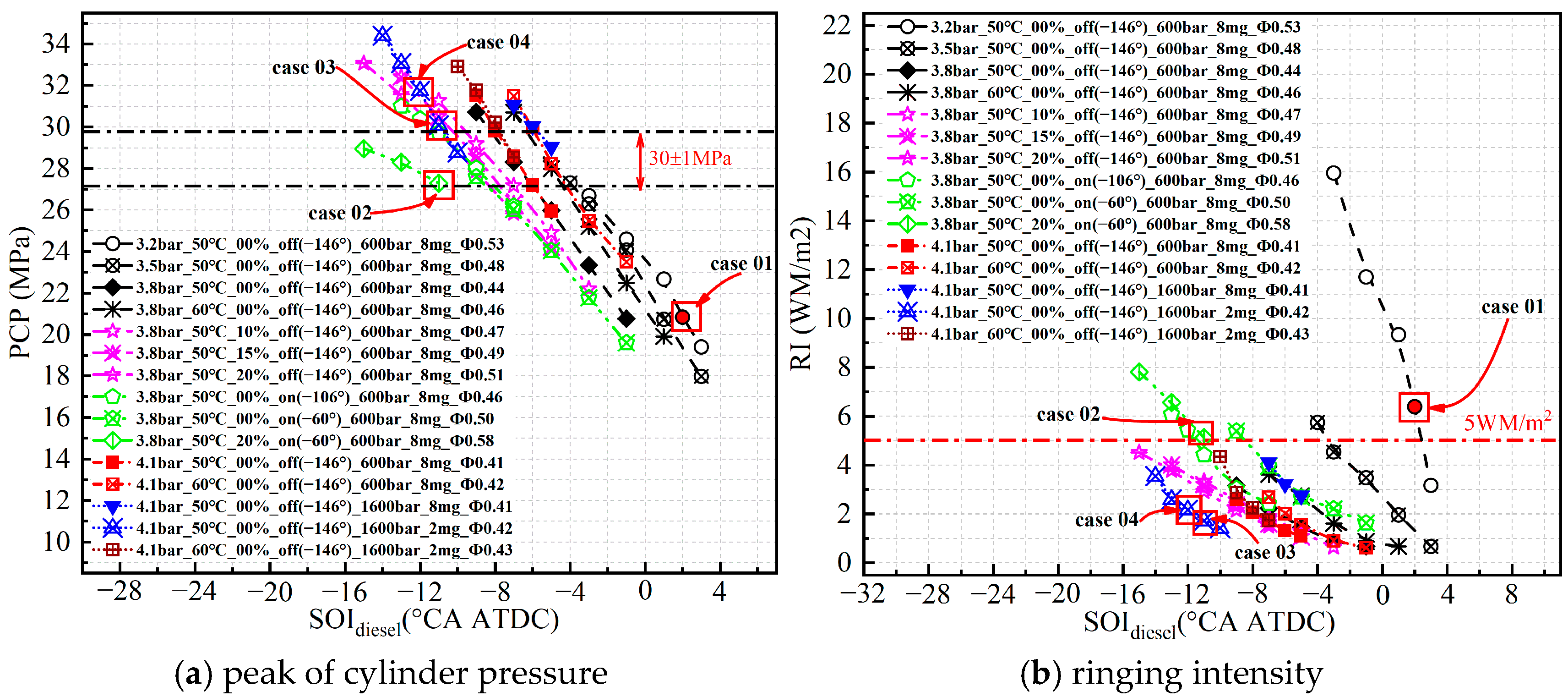
Figure 5 presents the engine PCP and RI under TAC-HCCI combustion, where RI represents the degree of rough combustion, which is related to the maximum pressure rise rate, the highest combustion pressure, the highest combustion temperature, etc. However, when RI ≤ 5 MW/m
2, it is considered that no rough combustion has occurred; when RI > 5 MW/m
2, it is believed that rough combustion will be triggered. The definition of RI can be obtained in reference [
29]. The numerical values in the annotations of the figure represent, in order, the intake pressure (bar), intake temperature (°C), EGR rate (%), intake valve closing timing (° CA ATDC), diesel injection pressure (bar), diesel injection quantity (mg), and equivalence ratio (-). It is also worth emphasizing that, under the conditions defined by the aforementioned variable parameters, the in-cylinder combustion process is regulated through adjustments to the diesel injection timing, where the abscissa in the figure represents the diesel injection timing. The annotations in subsequent figures follow the same interpretation.
As shown in
Figure 5, delaying the diesel injection timing and reducing the diesel injection quantity can effectively lower both PCP and RI. A high intake pressure decreases the in-cylinder mixture equivalence ratio, which contributes to reduced PCP and RI. A low intake temperature also helps reduce PCP and RI, primarily because it lowers both the mixture equivalence ratio and the pre-ignition temperature, thereby reducing the thermodynamic activity of the mixture and slowing the combustion heat release rate. The EGR rate has a relatively minor effect on the PCP and RI, likely due to the limited variation range of the EGR applied in this study, which was designed to maintain sufficient boost energy. Delaying IVCT can effectively reduce PCP; its effectiveness is constrained by the RI limit (≤5 ± 0.5 MW/m
2) beyond a certain delay threshold. Increasing the diesel injection pressure raises both the PCP and RI, as a higher diesel injection pressure enhances diesel spray diffusion, leading to a larger initial ignition zone and an earlier combustion phase.
A brief description of the special operating conditions (case 01, 02, 03, and 04) marked in
Figure 5 is provided below. These important operating conditions will be discussed and analyzed in detail in the following sections.
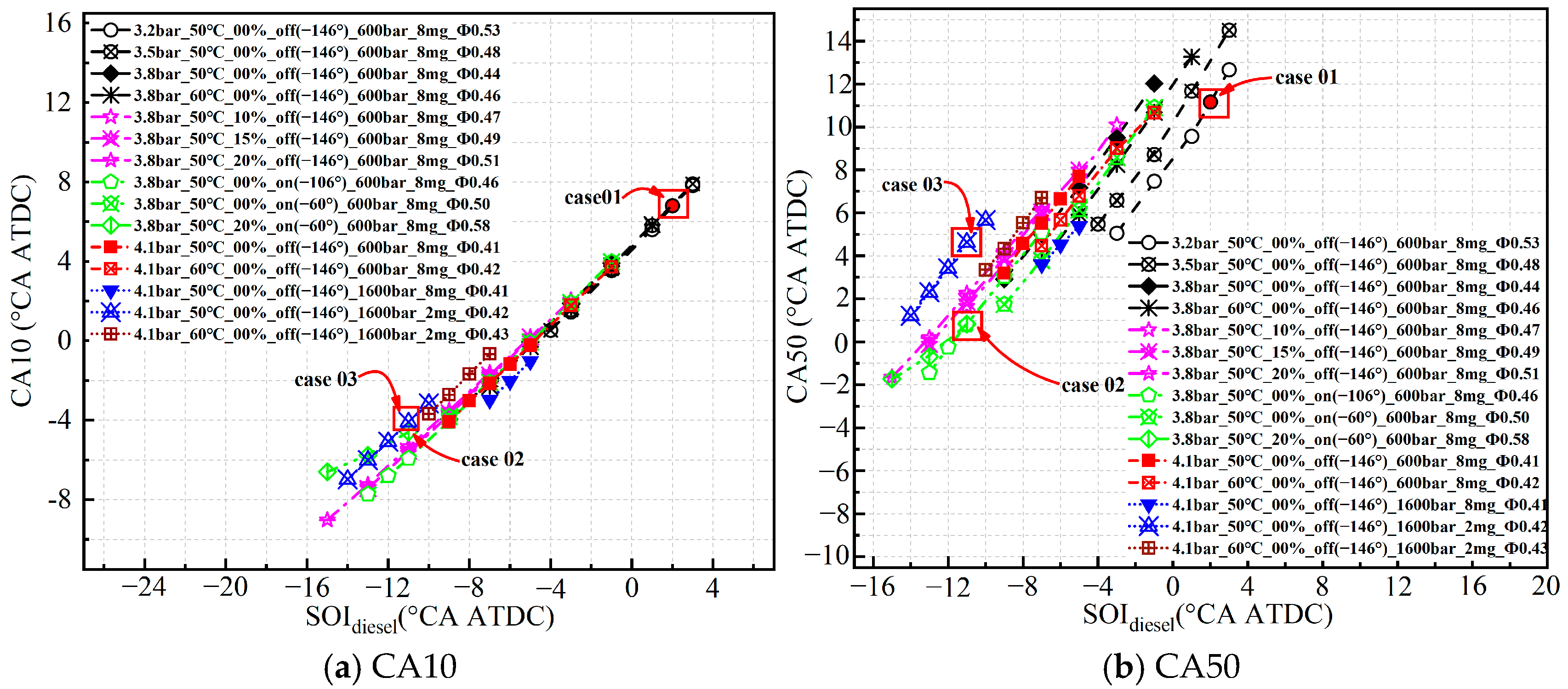
Figure 6 presents the combustion phase of the engine under TAC-HCCI combustion. As shown in
Figure 6a, the combustion phase CA10, which indicates the ignition timing, remains nearly constant when varying the intake pressure, intake temperature, EGR rate, and IVCT. Delaying diesel injection, reducing the diesel injection pressure, and decreasing the injection quantity can all significantly delay the combustion phase CA10. Therefore, adjusting diesel-related parameters in TAC-HCCI combustion enables effective control over the ignition timing of the in-cylinder mixture. As illustrated in
Figure 6b, the combustion phase CA50 is strongly influenced by the diesel injection timing. However, variations in the intake pressure, intake temperature, EGR rate, IVCT, diesel injection pressure, and diesel injection quantity have a more pronounced effect on the combustion phase CA50 compared to CA10. Increasing the intake pressure significantly delays the CA50. An increase in the EGR rate has a relatively minor influence on both CA10 and CA50. Elevating the intake pressure, delaying IVCT, and applying a higher diesel injection pressure tend to advance CA50, whereas reducing the diesel injection quantity results in a delayed CA50.
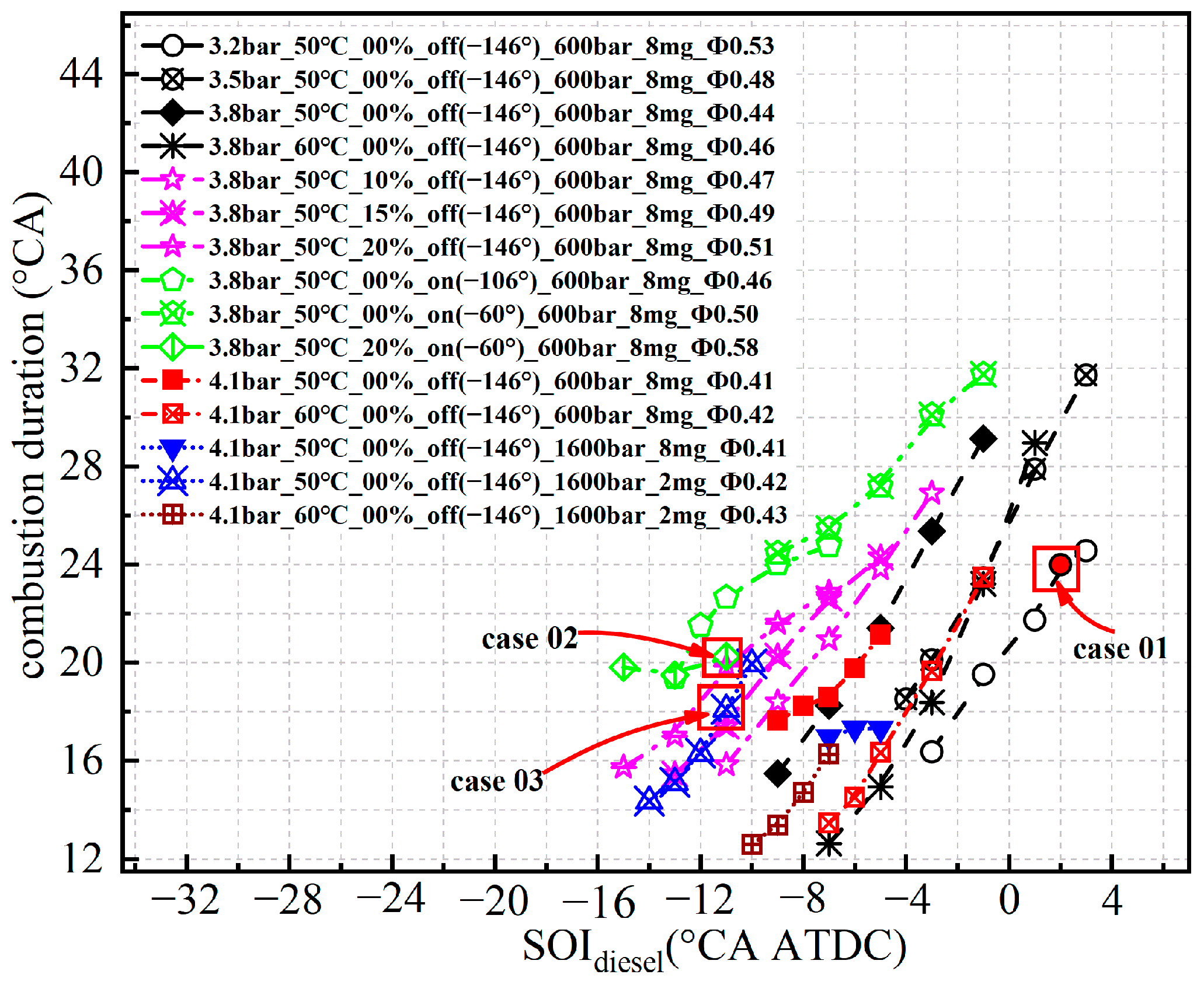
Figure 7 presents the combustion duration (CA90-CA10) of the engine under TAC-HCCI combustion. As shown in
Figure 7, retarding the diesel injection timing leads to an extended combustion duration. The combustion duration generally increases with higher intake pressure. However, when the intake pressure is increased from 3.8 bar to 4.1 bar, the combustion duration remains nearly constant at diesel injection timings of −7° CA ATDC, −6° CA ATDC, and −5° CA ATDC, respectively. This phenomenon can be attributed to the fact that as the intake pressure rises, the equivalence ratio of the in-cylinder mixture decreases, resulting in reduced mixture activity and a prolonged combustion duration. However, further increases in intake pressure elevate the pre-ignition pressure within the cylinder, thereby enhancing the mixture activity and shortening the combustion duration. Retarding IVCT generally extends the combustion duration, although this effect diminishes when the diesel injection timing is significantly delayed (later than −1° CA ATDC). Increasing the diesel injection pressure reduces the combustion duration, with a more pronounced effect observed when diesel injection is retarded. Reducing the quantity of diesel injection prolongs the combustion duration.
3.2. Energy Distribution Characteristics
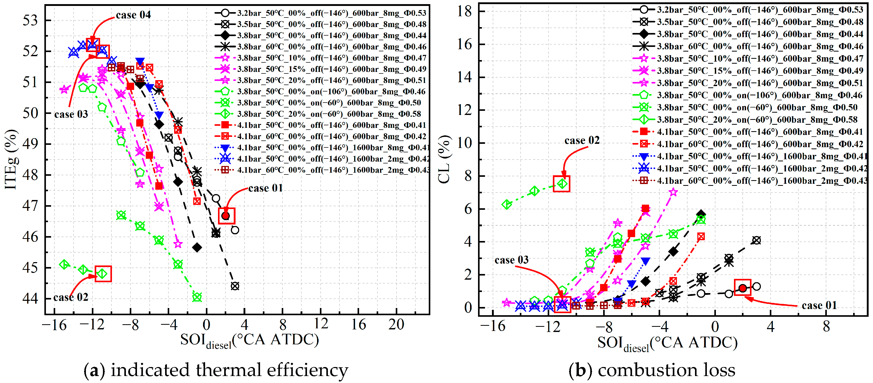
Figure 8 presents the gross indicated thermal efficiency (ITEg) and combustion loss (CL) of the engine under TAC-HCCI combustion. As shown in
Figure 8a, delaying diesel injection timing results in an initial increase followed by a decrease in ITEg, indicating the presence of an optimal diesel injection timing that maximizes ITEg. Increasing the intake pressure in conjunction with moderately advancing the diesel injection timing contributes to achieving higher ITEg. Under varying intake temperatures, the optimal diesel injection timing becomes increasingly delayed as the intake temperature decreases. Moreover, adjusting the diesel injection timing at a lower intake temperature (50 °C) is beneficial for improving the thermal efficiency of the engine. However, operating without EGR is more favorable for achieving high ITEg. As IVCT is delayed, the diesel injection timing must be advanced to maintain optimal thermal efficiency. Nevertheless, an IVCT of −146° CA ATDC is advantageous for achieving high ITEg. Notably, when the intake pressure and temperature are 3.8 bar and 50 °C, respectively, and the IVCT (−60° CA ATDC) and EGR rate (20%) are applied (case 02), even significantly advancing the diesel injection timing leads to a severe deterioration in engine thermal efficiency. Simultaneously increasing the diesel injection pressure and reducing the diesel quantity proves more effective in enhancing thermal efficiency. When the intake pressure and temperature are 4.1 bar and 50 °C, respectively, the diesel injection pressure is 1600 bar, the diesel injection quantity is 2 mg, the diesel injection timing is −11° CA ATDC, IVCT is −146° CA ATDC, and the EGR rate is 0%, the thermal efficiency optimization case (case 03) is achieved, yielding an ITEg of 52.0%. To further illustrate the potential of TAC-HCCI combustion to improve engine thermal efficiency,
Figure 8a indicates that the maximum ITEg achievable without constraints on PCP and RI is 52.2% (case 04), with diesel injection timing set at −11° CA ATDC.
As illustrated in
Figure 8b, under varying intake pressures, intake temperatures, EGR rates, IVCTs, diesel injection pressures, and diesel injection quantities, CL increases significantly when the diesel injection timing is delayed beyond a certain threshold. In TAC-HCCI combustion, earlier diesel injection timing, a lower intake pressure, higher intake temperature, earlier IVCT, and reduced EGR rate are conducive to achieving lower CL. Notably, the case 03 achieves near-zero CL (0.15%), primarily due to earlier diesel injection and a higher diesel pressure. In contrast, CL in case 02 deteriorates significantly, exceeding 7.0%, which is the primary factor contributing to the substantial decline in ITEg, despite relatively advanced CA10 and CA50 values. For case 01, although the intake pressure is lower, the higher in-cylinder mixture equivalence ratio (φ = 0.53) enhances mixture reactivity. Consequently, even with diesel injection timing delayed to 2° CA ATDC, CL remains relatively low at approximately 1.0%. This case is considered to represent a baseline condition with the excessively high thermodynamic activity of the mixture.
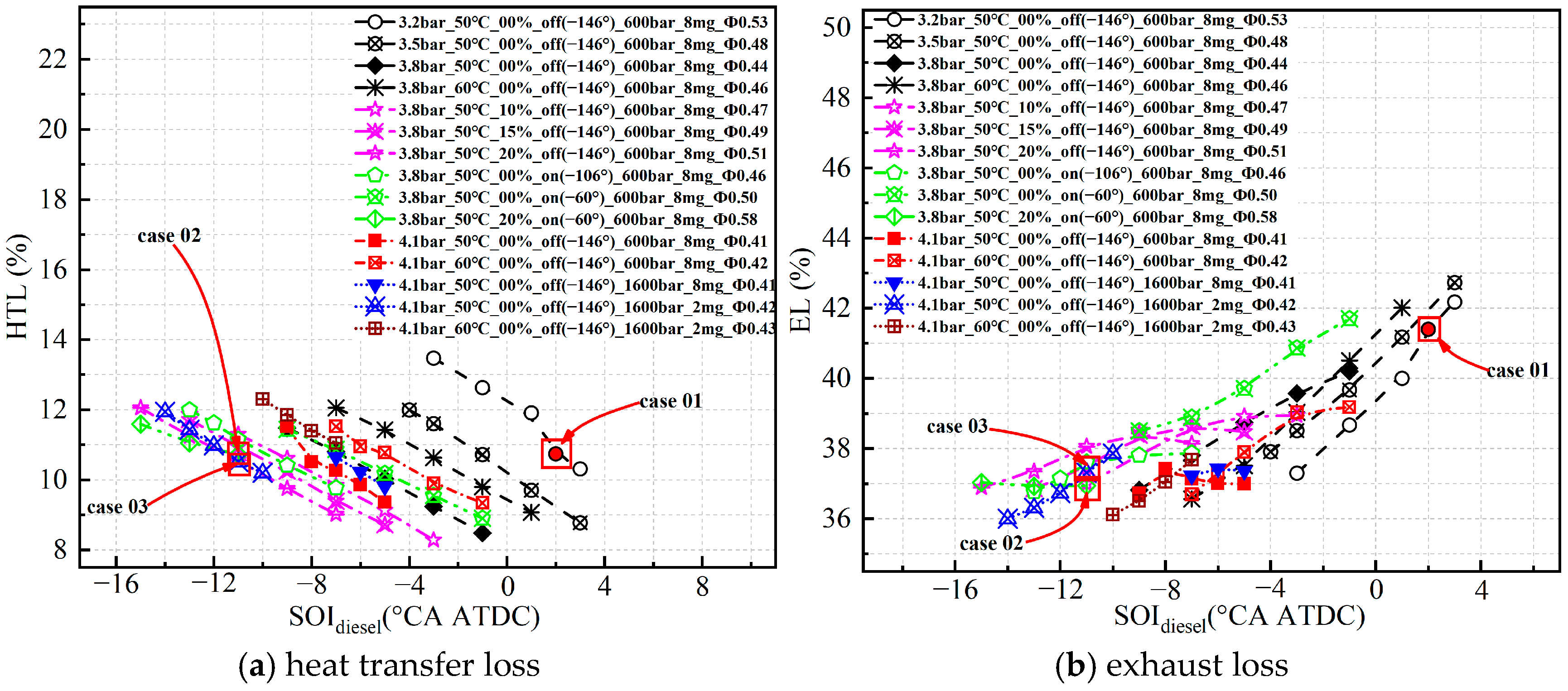
Figure 9 presents the heat transfer loss (HTL) and exhaust loss (EL) of the engine under TAC-HCCI combustion. As illustrated in
Figure 9a, the overall HTL in TAC-HCCI combustion is relatively low, predominantly below 12.0%. This is primarily attributed to the uniform distribution of natural gas within the combustion chamber, which preserves the low-temperature combustion advantage characteristic of HCCI combustion. An elevated intake pressure, reduced intake temperature, and increased EGR rate all contribute to lower HTL. Notably, as IVCT is delayed, the HTL initially decreases and subsequently increases. This behavior is mainly due to the reduction in the effective compression ratio caused by delayed IVCT, which lowers the pre-ignition mixture temperature and facilitates lower combustion temperatures. However, with a further delay in IVCT, the in-cylinder mixture equivalence ratio significantly increases, leading to higher combustion temperatures. Additionally, a lower diesel injection pressure and reduced diesel injection quantity help minimize HTL.
As illustrated in
Figure 9b, the engine EL increases with the retardation of diesel injection timing. This is primarily due to the delayed combustion phase (CA10, CA50) caused by late diesel injection, which results in a higher exhaust temperature. With increasing intake pressure, EL initially rises and then decreases. This behavior can be attributed to the fact that a higher intake pressure leads to a greater exhaust volume, thereby increasing EL. However, a higher intake pressure corresponds to a lower mixture equivalence ratio, which reduces the combustion temperature and subsequently lowers the exhaust temperature. Therefore, EL is determined by the combined effects of exhaust volume and exhaust temperature. When diesel injection timing is retarded, EL under a high intake temperature first remains lower than that under a low intake temperature and then becomes higher. This phenomenon may be explained by the fact that, at earlier diesel injection timings, the combustion of the in-cylinder mixture is more complete, with minimal differences in post-combustion temperatures. In such cases, EL mainly depends on exhaust volume, where a lower intake temperature correlates with a higher exhaust volume. When diesel injection timing is significantly delayed, combustion deteriorates, and a higher intake temperature causes a substantial increase in the exhaust temperature, leading to higher EL. Delaying IVCT also increases EL. In contrast, the diesel injection pressure and injection quantity have minimal influence on EL.
Case 01 achieves low CL and low HTL; however, the relatively high EL ultimately results in low thermal efficiency. Although case 02 exhibits similar levels of HTL and EL to case 03, its severe CL prevents it from achieving high thermal efficiency. In case 03, HTL and EL are 10.51% and 37.31%, respectively. Although the HTL and EL in case 02 are comparable to those in case 03, the significantly higher CL ultimately leads to a lower overall thermal efficiency. In case 03, the HTL and EL are 10.51% and 37.31%, respectively.
3.3. Emission Characteristics
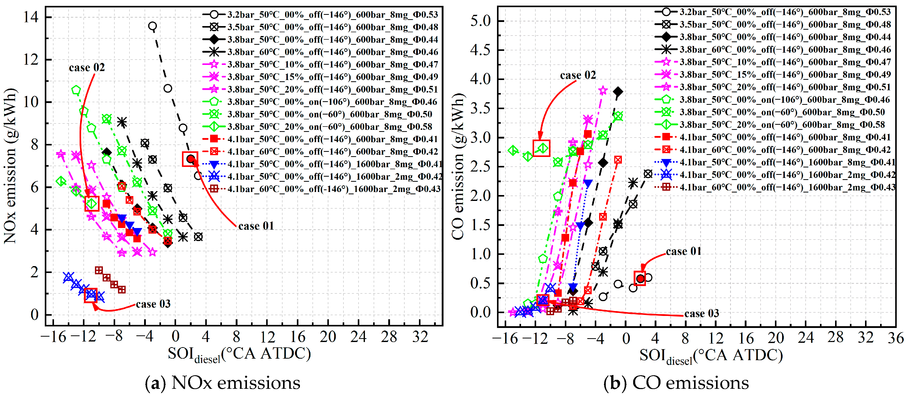
Figure 10 presents the NOx and CO emissions of the engine under TAC-HCCI combustion. As shown in
Figure 10a, engine NOx emissions exhibit a decreasing trend with the retardation of diesel injection timing. Elevating the intake pressure, lowering the intake temperature, and increasing the EGR rate are all conducive to achieving lower NOx emissions. At a given diesel injection timing, NOx emissions increase significantly when IVCT is delayed to a certain extent (−60° CA ATDC). Notably, a diesel injection quantity of 2 mg effectively reduces NOx emissions compared to 8 mg; however, variations in the diesel injection pressure have a minimal effect on NOx emissions. Cases 01 and 02 exhibit higher NOx emissions, whereas under the constraints of engine PCP ≤ (30 ± 1) MPa, and RI ≤ (5 ± 0.5) MW/m
2, the optimized thermal efficiency case 03 achieves a NOx emission of 1.0 g/kW∙h.
As shown in
Figure 10b, engine CO emissions increase significantly with the retardation of diesel injection timing. Elevating the intake pressure, increasing the EGR rate, and delaying IVCT all contribute to higher CO emissions. Conversely, increasing the intake temperature and diesel injection pressure are both effective in reducing CO emissions. It is also noteworthy that, even when the diesel injection quality is relatively low, a lower CO emission level can still be achieved by adjusting the diesel injection timing. This is because reducing the diesel injection quantity increases the amount of premixed natural gas in the cylinder, thereby increasing the mixture equivalence ratio and enhancing the activity of the mixture. At the same time, it allows for advancing diesel injection timing, which promotes more complete combustion and consequently reduces CO emissions. Case 02 exhibits a significant deterioration in CO emissions, which is consistent with its high CL. In the thermal efficiency optimization case 03, CO emissions are reduced to 0.2 g/kW∙h.
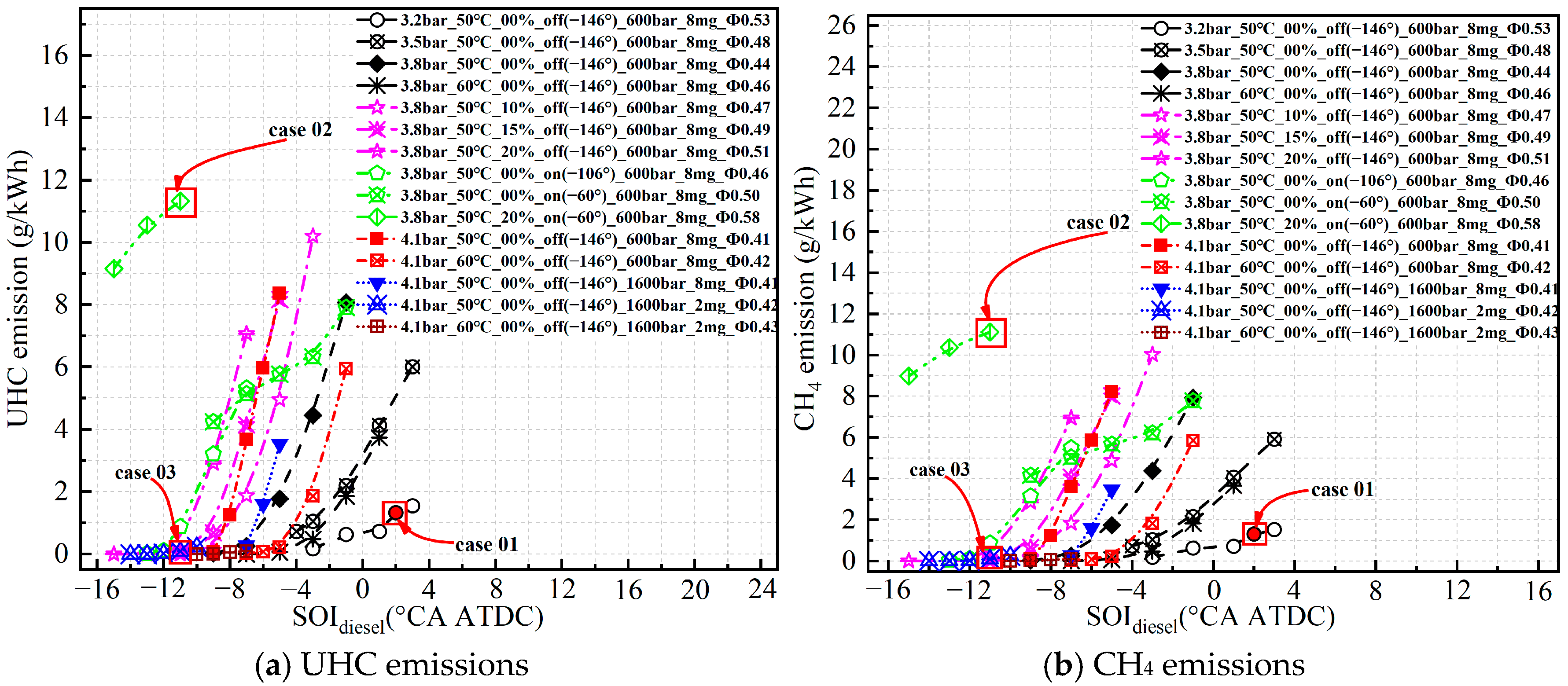
Figure 11 presents the UHC and CH
4 emissions of the engine under TAC-HCCI combustion. The data indicate that CH
4 constitutes the primary component of UHC emissions, suggesting a strong correlation between the emission characteristics of UHC and CH
4. Both UHC and CH
4 emissions increase as diesel injection timing is retarded. Advancing diesel injection timing, increasing the intake pressure, reducing the EGR rate, and elevating the diesel injection pressure are all effective strategies for minimizing UHC and CH
4 emissions. It is noteworthy that, adjusting the diesel injection timing at low diesel injection quantities enables the achievement of low UHC and CH
4 emissions, as demonstrated in case 03. In contrast, case 02 exhibits significantly increased UHC and CH
4 emissions. This deterioration aligns with its high CL. Meanwhile, in case 01, UHC and CH
4 emissions remain at relatively low levels.
3.4. Equivalence Ratio and Temperature Distribution Characteristic
This section provides a comprehensive explanation and analysis of the in-cylinder mixture equivalence ratio and temperature distribution for case 01, 02, and 03. The objective is to identify the combustion characteristics of TAC-HCCI that enable high thermal efficiency and low emissions, and to ultimately define the core technologies and combustion control strategies for implementing TAC-HCCI combustion.
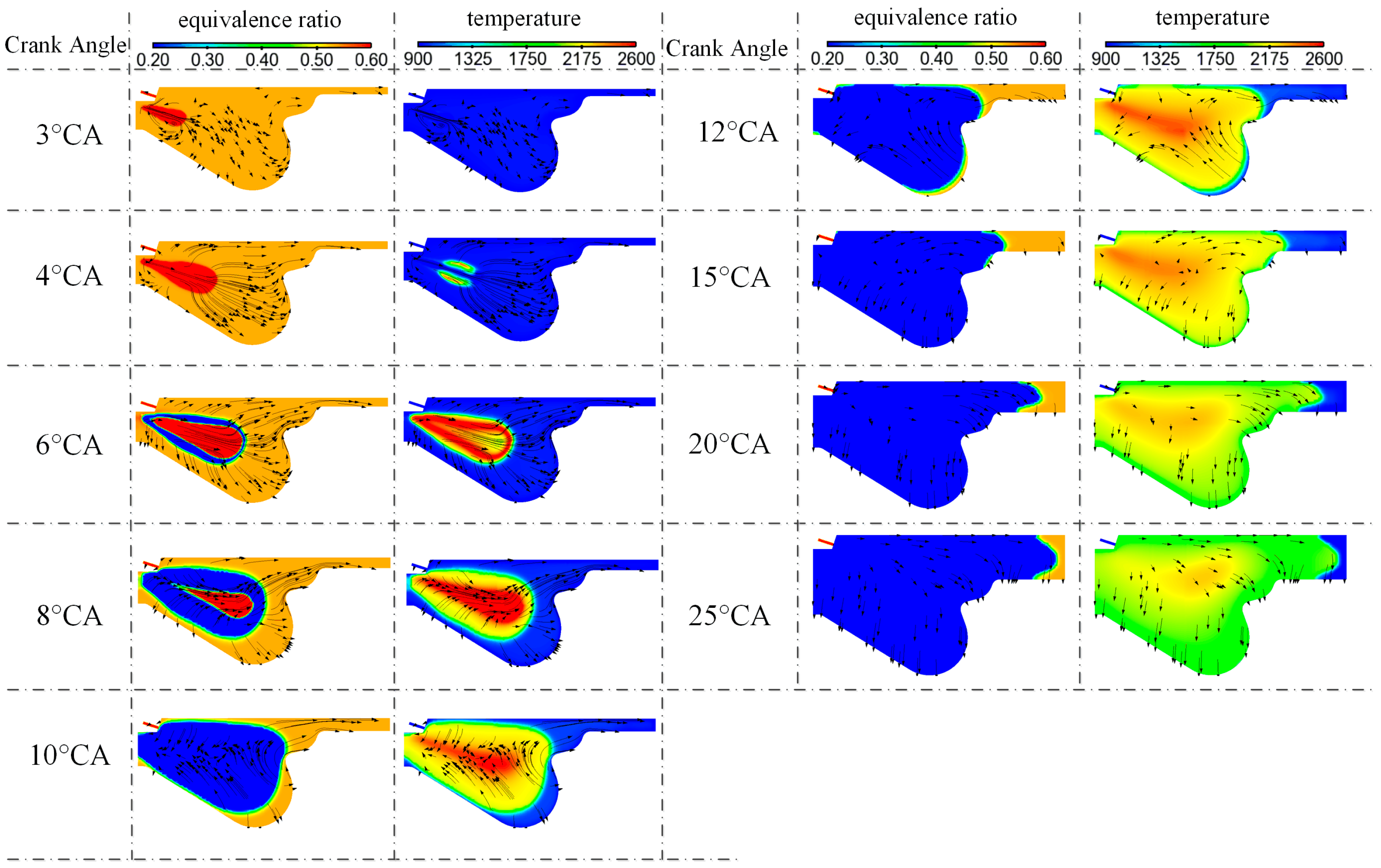
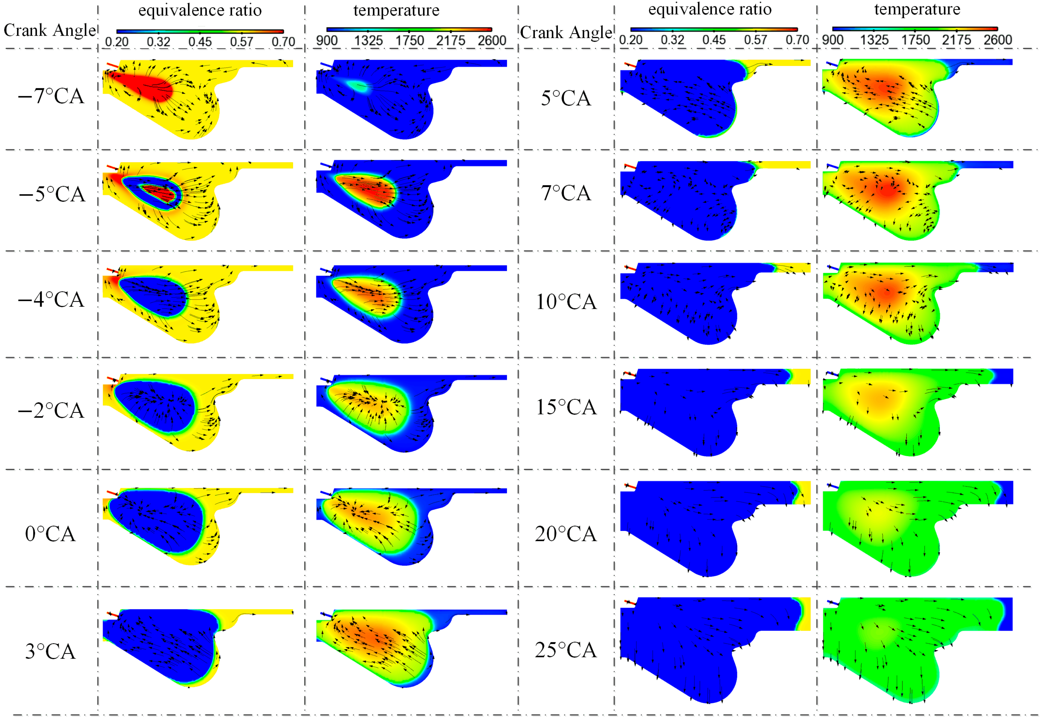
Figure 12 presents the in-cylinder mixture equivalence ratio and temperature contour plots for case 01. The black arrow lines in the figure indicate the streamline distribution within the cylinder, the same as
Figure 13, and 14. At 2° CA ATDC, 8 mg of pilot diesel fuel is injected into a homogeneous natural gas mixture with an equivalence ratio of 0.53. Shortly after injection, at 4° CA ATDC, ignition initiates primarily at the periphery of the diesel spray. The micro-pilot diesel injected near top dead center undergoes predominantly diffusion combustion, resulting in localized regions with temperatures exceeding 2600 K after combustion. Subsequently, the homogeneous natural gas mixture adjacent to the diesel spray undergoes rapid combustion and releases heat. However, as the piston descends, in-cylinder temperatures decrease, leading to a reduction in the chemical activity of the premixed natural gas mixture. Consequently, a portion of the natural gas remains unburned even at 25° CA ATDC.
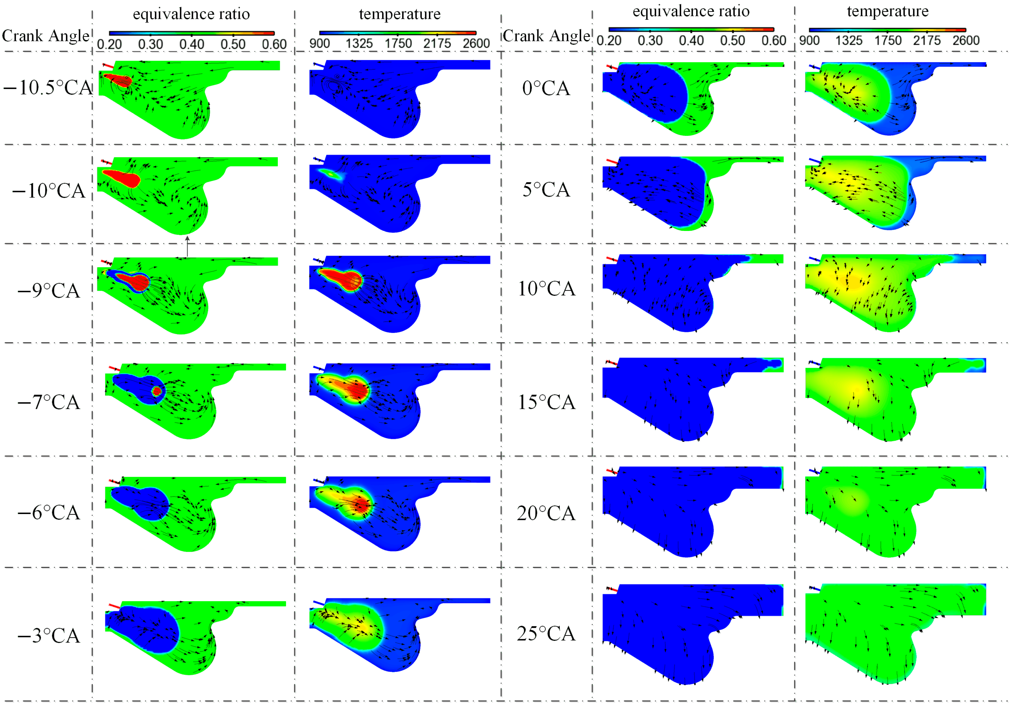
Figure 13 presents the in-cylinder mixture equivalence ratio and temperature evolution for case 02. At −11° CA ATDC, 8 mg of pilot diesel fuel is injected into a homogeneous natural gas mixture with an equivalence ratio of 0.58. Diesel ignition initiates at −7° CA ATDC. In case 02, the diesel ignition delay is longer compared to case 01, primarily due to the delayed IVCT and the application of EGR, both of which result in a lower in-cylinder temperature prior to ignition. The diesel spray penetration distance in case 02 is shorter than in case 01, mainly because of the higher in-cylinder charge density in case 02. Consequently, with the same pilot diesel quantity, the area (volume) of the local high-temperature region (exceeding 2600 K) formed in case 02 is smaller than that in case 01. Observation of the combustion temperature of the in-cylinder homogeneous natural gas mixture indicates that the combustion temperature in case 01 is higher than in case 02. A greater proportion of the mixture exceeds 2200 K in case 01, leading to higher NOx emissions. The higher NOx emissions in case 01 compared to case 02 can be attributed to two factors: the larger high-temperature zone generated by diesel combustion in case 01, and the greater amount of homogeneous natural gas burned above 2200 K. However, due to lower combustion temperatures in case 02 compared to case 01, a larger quantity of unburned natural gas mixture remains at 20° CA ATDC. As the piston descends and in-cylinder temperatures continue to decrease, case 02 produces significant amounts of UHC and CO, ultimately resulting in increased CL.
Figure 14 presents the combustion process in the cylinder under the thermal efficiency optimization case 03. At −11° CA ATDC, 2 mg of micro-pilot diesel is injected into a homogeneous natural gas mixture with an equivalence ratio of 0.42. Ignition occurs in the cylinder at −10° CA ATDC. Compared to cases 01 and 02, case 03 exhibits the shortest diesel ignition delay, primarily due to the higher diesel injection pressure. At −9° CA ATDC, the temperature within the diesel spray region exceeds 2600 K; the area (volume) of the high-temperature zone (over 2600 K) is significantly smaller than that observed in case 01 and 02. This is mainly attributed to the reduced quantity of pilot diesel injected. As the diesel burns and releases heat, the adjacent natural gas mixture undergoes rapid combustion and heat release. Due to the low equivalence ratio of the natural gas mixture, its post-combustion temperature is below 2200 K. Simultaneously, the high-temperature region formed by diesel combustion rapidly diminishes, and by −3° CA ATDC, there is essentially no region with a temperature exceeding 2200 K remaining in the cylinder. These characteristics contribute to significantly lower NOx emissions in case 03 compared to cases 01 and 02. Although the equivalence ratio of the natural gas mixture is lowest in case 03, combustion is nearly complete by 20° CA ATDC.
In summary, the addition of pilot diesel in diesel/natural gas dual-fuel TAC-HCCI combustion effectively controls the combustion phase, ensuring the efficient and stable combustion of the mixture in the cylinder. Within the TAC-HCCI combustion framework, two key combustion requirements must be met: first, complete and thorough combustion of the mixture, and second, maintaining the lowest possible combustion temperature to minimize CL and HTL. Although diesel/natural gas dual-fuel TAC-HCCI combustion is primarily governed by the activity of the natural gas mixture, a high diesel injection pressure and low diesel injection quantity are effective in achieving low NOx emissions.
In this study, under high engine load conditions (IMEPg 24 bar), with PCP ≤ (30 ± 1) MPa, RI ≤ (5 ± 0.5) MW/m2, and without employing late IVCT and EGR, an intake temperature of 50 °C, a mixture equivalence ratio at 0.42, a diesel injection quantity of 2 mg, and a diesel injection pressure 0f 1600 bar were applied. These settings enabled the engine to achieve an ITEg of up to 52.0%, with NOx emissions of 1.0 g/kW∙h, UHC emissions of 0.1 g/kW∙h, and CO emissions of 0.2 g/kW∙h. This combustion strategy successfully addresses the load expansion limitations of conventional HCCI combustion while preserving its advantages of high efficiency and low emissions.


