Abstract
This study proposes a new air treatment system that integrates dehumidification, cooling, and water recovery using a Horizontal Air–Ground Heat Exchanger (HAGHE) combined with Peltier cells. The airflow generated by a fan flows through an HAGHE until it meets a septum on which Peltier cells are placed, and then separates into two distinct streams that lap the two surfaces of the Peltier cells: one stream passes through the cold surfaces, undergoing both sensible and latent cooling with dehumidification; the other stream passes through the hot surfaces, increasing its temperature. The two treated air streams may then pass through a mixing chamber, where they are combined in the appropriate proportions to achieve the desired air supply conditions and ensure thermal comfort in the indoor environment. A Computational Fluid Dynamics (CFD) analysis was carried out to simulate the thermal interaction between the HAGHE and the surrounding soil. The simulation focused on a system installed under the subtropical climate conditions of Nairobi, Africa. The simulation results demonstrate that the HAGHE system is capable of reducing the air temperature by several degrees under typical summer conditions, with enhanced performance observed when the soil is moist. Condensation phenomena were triggered when the relative humidity of the inlet air exceeded 60%, contributing additional cooling through latent heat extraction. The proposed HAGHE–Peltier system can be easily powered by renewable energy sources and configured for stand-alone operation, making it particularly suitable for off-grid applications.
1. Introduction
Geothermal energy constitutes a particularly compelling form of renewable energy, primarily due to its inherent capacity to deliver a continuous, stable supply of thermal energy throughout the entire year [1]. Unlike solar or wind energy, geothermal systems remain largely impervious to climatic variability and seasonal fluctuations, thus positioning them as a highly reliable and sustainable energy source [2]. Among the various technological implementations of geothermal energy, geothermal heat pump (GHP) systems, particularly ground source heat pumps (GSHP), emerge as a prominent application [3]. These systems exploit the Earth’s relatively constant subsurface temperatures to provide efficient heating and cooling for buildings and indoor environments. For example, in the study presented by Ben et al. [4], the feasibility of decarbonising buildings by applying an adaptive thermal comfort strategy in combination with a closed-loop deep geothermal system was studied. In a comprehensive study, Violante et al. [5] provided an in-depth comparison between GSHP systems and conventional heating and cooling technologies, particularly in the context of decarbonising the thermal energy sector. Their findings underscore the energy efficiency and reduced greenhouse gas emissions associated with geothermal systems, thereby highlighting their strategic importance in meeting sustainability targets. GSHP systems have also been applied in the city of Dushanbe, through the project of Bina et al. [6]: the research used numerical simulations validated with real data recorded in the field and provides a comprehensive analysis of both short- and long-term performance by implementing the model using FEFLOW (Finite Element subsurface FLOW system, 8.1) software version 8.1. While Li et al. [7] used a predictive model to analyse the performance degradation of the GSHP system induced by thermal imbalance in the soil. The performance of such systems can also be influenced by other parameters, such as soil temperature: this is the case in the study by Zhou et al. [8]. The relationship between soil temperature variation and depth was analysed, as well as the impact of geological distributions in a simulation environment to test certain hypotheses that emerged from the analysis of monitoring data. Beyond overarching comparisons, numerous studies have delved into the nuanced technical aspects of geothermal system design and operation. In a related line of inquiry, Bhutta et al. [9] demonstrated the efficacy of CFD as a powerful analytical tool for the simulation and performance enhancement of diverse heat exchanger designs. Another investigation [10] presented the experimental validation of a CFD-based mathematical model developed using Fluent. This model was specifically tailored to simulate thermal exchange within a Horizontal Air–Ground Heat Exchanger (HAGHE) system deployed in conjunction with GSHPs. Validation was achieved through comparison with empirical data obtained from a real-world installation located in Rubiana (Turin, Italy). In the HVAC (Heating, Ventilation, and Air Conditioning) sector, horizontal ground heat exchangers are a significant component in achieving energy requirements. In the work of Bordignan et al. [11], a complex system was realised consisting of an air-to-air heat pump coupled with a heat recovery unit capable of pre-heating the outside air and contributing to the production of domestic hot water. The horizontal ground heat exchanger, indeed, had a complex heat transfer mechanism, so in a study [12], a hybrid numerical model was created to provide efficient modelling and dynamic optimisation support. Additional advancements in geothermal system design have been proposed by Lamarche et al. [13], who introduced innovative methodologies for the configuration of geothermal boreholes. Additional advancements in geothermal system design have been proposed by Lamarche et al. [13], who introduced innovative methodologies for the configuration of geothermal boreholes. Their work emphasised the critical role of borehole characteristics and utilised the g-function approach—a sophisticated modelling technique—for capturing the dynamic thermal behaviour of underground piping systems. Similarly, Priarone et al. [14] employed the Finite Line Source (FLS) model within the COMSOL 2008 Multiphysics environment to simulate heat transfer processes, incorporating a broader set of variables to reflect real-world operating conditions with greater fidelity. A similar approach has recently been used to model a new horizontal geothermal exchanger system integrated with a borehole thermal energy storage [15]. Misra et al. [16,17] performed CFD simulations to assess the influence of operating time and soil thermal conductivity on the effectiveness of earth–air heat exchange systems (also known as earth–air tunnels). These systems were utilised for both cooling and heating applications and present an environmentally sustainable alternative for climate control in buildings. However, recent studies focused on another type of heat exchanger. Chiesa [18] presented a method for analysing the potential of this technique at specific sites, to optimise it and verify its ability to meet the building’s expected energy demand as soon as possible, by developing three key performance indicators (KPIs). The method could be a suitable solution for utilising low-temperature ground in summer, but the performance of the EAHX system in different climates has not been assessed. Therefore, Li et al. [19] evaluated the energy-saving potential of the EAHX system in a multi-story building with the Passivhaus standard in different cities in China with different climatic conditions. They investigated GSHPs and ASHPs (Air Source Heat Pumps) in six different cities in Morocco and found that the application of these systems can provide significant energy savings, mainly in colder regions [20]. The use of earth-to-air heat exchangers (EAHXs) can be a supporting tool for ventilation in buildings, with the aim of improving thermal comfort and reducing dependence on conventional Heating, Ventilation, and Air Conditioning (HVAC) systems [21]. Wakil et al. [22] proposed an optimisation algorithm under different seasonal conditions. Ghosal et al. [23], on the other hand, developed a thermal model to study the potential of utilising the thermal energy stored in the soil for greenhouse heating and cooling, using an earth-to-air heat exchanger (EAHX) system integrated into a greenhouse located in India. An additional frontier in thermal management and energy efficiency lies in the application of thermoelectric technologies, particularly Peltier cells. These solid-state devices, which resemble compact plates, operate based on the thermoelectric effect, enabling heat to be transferred from one surface to another. As such, they offer a highly versatile solution for localised heating and cooling. Mannella et al. [24] supported the design of temperature control systems by simplified modelling of heat transfer dynamics with Peltier cells. Casano et al. [25] conducted an experimental investigation to characterise the performance of thermoelectric modules used for power generation on a range of different resistive loads. In contrast, Shi et al. [26] used a different number of Peltier modules to experimentally study the air-cooling process: in this way, an optimised number of modules can be selected for large-scale cooling through the simultaneous optimisation of multi-efficiency and cooling. Freire et al. [27] derived an extensive performance evaluation of Peltier modules, revealing their significant potential to enhance energy efficiency across various system configurations. Innovative implementations of Peltier technology have also been proposed in the domain of environmental control. For example, Nihat Dipova [28] developed an alternative humidity regulation system incorporating both Peltier modules and infrared heating elements. This novel device introduces new possibilities for humidity and temperature management in both industrial and residential environments. Congedo et al. [29] showed for the first time a conceptual design of the integration of the Peltier cells with the geothermal system. Lastly, Baglivo et al. [30] explored the integration of Peltier elements with EAHX systems, using a hybrid 3D + 1D FEM approach in COMSOL. The present study provides a preliminary CFD investigation of the thermal performance of a HAGHE operating under the subtropical climate conditions of Nairobi, Africa. First, the geothermal system is modelled through a three-dimensional CFD simulation in AnsysFluent 2023 R1, based on a numerical model previously developed and validated by the authors. The integration with Peltier cells is then analysed separately during the post-processing phase, using thermodynamic calculations based on the results of the CFD simulation. The proposed combined solution is further supported by the possibility of utilising recovered components from discarded electronic equipment, such as Peltier cells and heatsinks salvaged from end-of-life personal computers, thereby reducing costs and promoting circular economy practices. Additionally, the HAGHE–Peltier system can be easily powered by renewable energy sources and configured for stand-alone operation, making it a low-cost, easy-to-implement alternative that is particularly well-suited for sustainable air conditioning applications in developing countries.
2. Materials and Methods
Figure 1 presents a summary diagram of the HAGHE–Peltier system, illustrating the logical sequence of the steps followed in the methodology, along with the corresponding inputs and outputs of the problem.
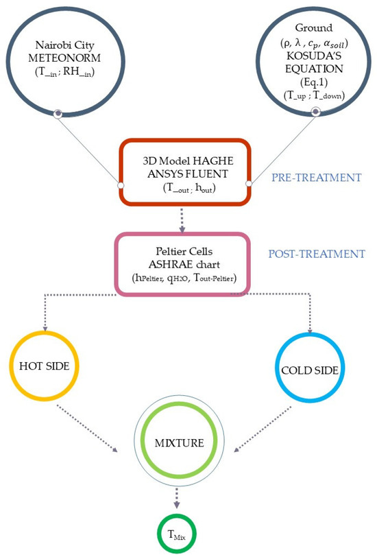
Figure 1.
Flowchart of the HAGHE–Peltier system.
In particular, the input data concern the climate data and the boundary conditions.
The reference city is Nairobi, for which climate data (T_in and RH_in) were extrapolated through Meteonorm, on an hourly and yearly basis.
The boundary conditions were defined by applying Kosuda’s equation (Equation (1)), using the soil properties λ, ρ, , in order to calculate the ground temperatures T_up and T_down at different depths, in particular, temperatures of the lowest and highest horizontal surfaces of the calculation domain by the CFD code Fluent. The HAGHE system was simulated in order to calculate the thermo-hygrometric outlet conditions T_out and hout of air from the geothermal probe, thus representing the air pre-treatment phase.
Later, in the Peltier section, the air flow is split into two flows, one laps the cold side and the other laps the hot side. Using the thermal power exchanged with both sides of the Peltier cells, the enthalpy variations of both flows are calculated by the use of the ASHRAE psychrometric diagram.
Finally, the idea is to use the correct mixing of the two flows to obtain the thermal comfort conditions in the conditioned room.
2.1. Pre-Treatment Phase: The HAGHE Model
The analysis employs a numerical approach based on CFD analysis, implemented using the CFD code Ansys Fluent 2023 R1, to model the complex thermal interactions occurring within the system. The HAGHE system shows a geometrically symmetrical configuration. This symmetry-based modelling strategy, illustrated in Figure 2, permits a significant reduction in the computational cost of the simulations, both in terms of time and processing resources. The specifications of the computational system used for this study are summarised in Table 1.
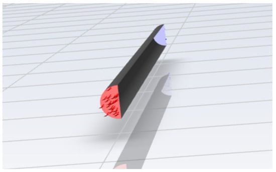
Figure 2.
Geothermal thermal exchanger model.

Table 1.
Mesh size in Ansys analysis software.
The air duct in expanded polystyrene (EPS) has a semi-cylindrical geometry, with a wall thickness of 20 mm and a base surface area of 0.0157 m2. The pipe is embedded within a defined computational domain shaped as a parallelepiped, with dimensions of 5.0 m in length, 2.0 m in width, and 4.0 m in depth, as schematically depicted in Figure 3.The inlet and outlet sections are indicated in red and blue respectively, while the symmetry section of the object is indicated in yellow.
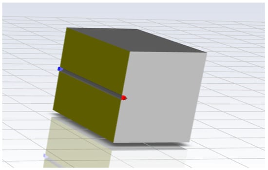
Figure 3.
Representation of the complete geometric model in Ansys.
In CFD simulations, the accuracy in defining numerical models has a significant impact on the ability to correctly represent the phenomenon of thermal energy storage. With this objective, a computational model was developed that includes an extensive solid domain (the ground) surrounding the geothermal probe.
Moreover, the thermal capacity of the soil is considerably higher than that of air; as a result, the temperature gradient within the various soil layers is primarily influenced by the temperatures at the upper and lower boundaries of the domain, rather than by the heat exchange with the geothermal probe itself, which is consistent with what occurs under real operating conditions.
To enable a reliable and efficient simulation, the domain was discretised using a non-uniform, structured mesh composed of hexahedral cells. The mesh density is highest close to the pipe, where thermal gradients and flow dynamics are most pronounced, and becomes progressively coarser with increasing distance from the buried pipe. The meshing strategy reflects the curved geometry of the semi-cylindrical surface while gradually transitioning into a regular grid structure in the surrounding soil. This graded meshing approach enhances numerical stability and accuracy, optimising the resolution of temperature and velocity fields while minimising computational overhead. The continuous equations are approximated to discrete points within the mesh. In particular, the Navier–Stokes equations, averaged according to the Reynolds approach, were solved using an implicit second-order transient scheme, integrated with the k-ε turbulent model, including wall treatment and thermal effects. The k-ε model was adopted to simulate internal surface-adherent flows characterised by weak pressure variations. As for the calculation method, the SIMPLE algorithm (Semi-Implicit Method for Pressure-Linked Equations) was used, which allows the coupling of pressure and velocity mainly for applications with incompressible flow.
The assumption of incompressible air is justified by the low flow velocity (Mach < 0.3), which makes compressibility effects negligible. Density variations due to temperature and pressure are minimal, and the use of the SIMPLE algorithm ensures computational efficiency. This approach is widely validated in HVAC and geothermal applications, where thermal effects dominate over compressibility.
From a thermodynamic standpoint, the inlet boundary conditions are defined based on meteorological data obtained from Meteonorm [31,32,33] for the city of Nairobi, reflecting the local climatic conditions under which the system would operate in a real-world scenario. The airflow entering the pipe is set at a mass flow rate of 284.4 kg/h, simulating the forced convection of air through the buried exchanger.
To model the temperature profile in the soil as a function of depth () and time (), Kosuda’s equation was used in Equation (1):
where
- -
- is the average annual temperature.
- -
- is the annual temperature range/2.
- -
- is the days with the lowest temperatures.
- -
- is the hours of the year in question.
- -
- is the diffusivity of the soil.
- -
- is the burial depth.
- -
- is the period of the sinusoid.
This equation assumes a fundamental character for evaluating the temperature variations on the upper and lower surfaces of the model in contact with the ground. The burial depths considered were 1 m and 5 m, respectively. To perform the calculation, the parameters and soil properties indicated in Table 2 and Table 3 are used. These values are representative of a medium conductivity soil as reported in [34]. In particular, the soil under consideration is a high-moisture silty–sandy type, with a thermal conductivity of 2.0 W/m·K, which is consistent with high saturation conditions. It exhibits an average porosity ranging from 35% to 40%, and a volumetric water content of 28–30%, resulting in a relative saturation between 0.75 and 0.85. The dry bulk density is estimated at approximately 1700–1900 kg/m3, and the high moisture content enhances its thermal transfer capacity, making it suitable for interaction with geothermal exchange systems. The soil structure is compact and stable, with good granulometric continuity and no significant organic content.
Table 2.
Parameters of the soil profile.
Table 3.
Thermal parameters.
As can be seen from Figure 4, the temperatures of the soil undergo slight variations throughout the year at a depth of 1 m, peaking near 300 K. As the depth increases, the oscillations are stabilised, leveraging the characteristics of the soil and contributing to a nearly constant temperature trend throughout the entire year.
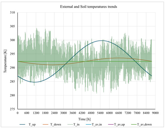
Figure 4.
External and Soil Temperature trends.
When comparing the temperature variations in the soil with loss of the external air (T_in), it can be concluded that the average temperature of the soil (T_av,up and T_av,down) coincides with the annual average temperature of the inlet air (T_av,in).
2.2. Post-Treatment Phase: The Peltier Cells
To complete the air conditioning treatment, the Peltier cells section follows the geothermal system. These devices, known for their ability to generate a thermal flux in response to an electric current, play a key role in amplifying the heat transfer initiated within the geothermal probe. At the outlet of the geothermal probe, a septum divides the pipe into two equal sections. Peltier cells that are activated according to a modulated sequential logic are sequentially installed on it so as to gradually increase the thermal power available in the system. In particular, four different configurations with increasing numbers of Peltier cells were considered: 1, 3, 5, and 7 cells.
Each Peltier module receives a cooling power of 0.083 kW on its cold side, while the hot side is subjected to a thermal power of 0.187 kW. Additionally, all cell-related quantities used in Table 4 are listed.
Table 4.
Peltier cell parameters.
The airflow within the duct is thus split: one stream passes through the cold side of the Peltier cells, undergoing further temperature reduction and more effective dehumidification; the other stream flows along the hot side, benefiting from the heat generated to increase the air temperature. If the incoming air temperature drops below the dew point, condensation of moisture is triggered directly within the probe. This occurs specifically in the airstream that passes through the cold side of the Peltier cells, as a result of the cooling and dehumidification process, with the condensate collected by gravity in a dedicated storage tank located at the base of the system.
This tank can also function as a mixing chamber where, by adjusting the two air flow rates, the desired thermal comfort conditions can be achieved in the conditioned environment.
Figure 5 reports the trend of the COPc of a Peltier cell as a function of ΔT. The theoretical cooling Coefficient of Performance (COPc) of the Peltier cell is defined as follows:
COPc = Qc/W
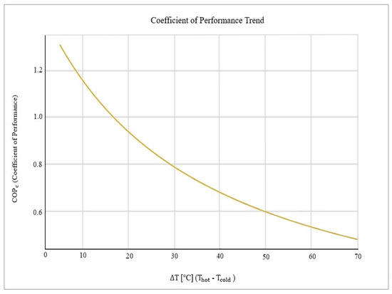
Figure 5.
COP trend of a Peltier cell as a function of ΔT.
- Qc: cooling power transferred from the cold side of the Peltier cell (W).
- W: electrical power absorbed by the module (W).
Trying to make a comparison with conventional heat pumps, Peltier modules generally have much lower COPc values (0.30.7) compared to vapour–compression refrigeration cycles, especially when operating with large temperature differences.
The COPc decreases as the temperature difference (ΔT) between the hot and cold sides increases. Performance can be improved by optimising the cooling of the hot side and reducing the input current to operate the module within its most efficient range.
Although an optimal value is not achieved, the device offers positive potential in terms of responding to the needs of thermal comfort.
3. Results and Discussion
3.1. Analysis of the HAGHE System
Figure 6 shows the inlet and outlet temperatures of the air passing through the probe, resulting from the CFD analyses. The results show a significant damping in the most extreme temperature variations.

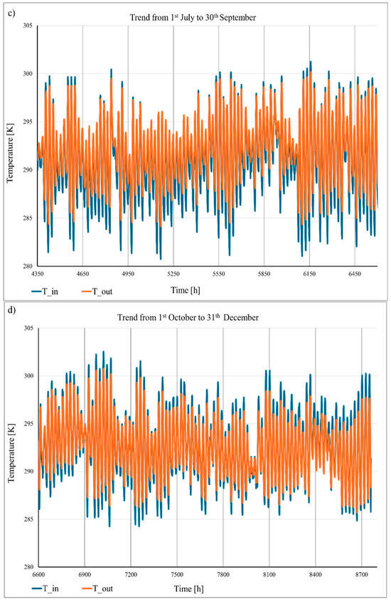
Figure 6.
Full-year temperature trends: (a) 1 January–31 March; (b) 1 April–30 June; (c) 1 July–30 September; and (d) 1 October–31 December.
Looking at Figure 6, in the geothermal probe crossing, there is a decrease in the maximum outlet temperature, which increases from 304.2 K to 300.79 K, and an increase in the minimum temperature value, which increases from 280.6 K to 284.15 K.
Leaving aside the extreme values, the trend shows almost uniform outlet temperatures, with no particularly marked distinctions between the different months of the year. This thermal behaviour is a clear consequence of the mild climatic conditions in the city of Nairobi and confirms the effectiveness of the probe in mitigating seasonal thermal fluctuations and ensuring more stable operating conditions.
Of the two flow rates, we will focus on the cooling treatment and subsequent condensate production.
3.2. Analysis of the HAGHE–Peltier System
This section investigates the mechanisms governing the formation and subsequent collection of condensate water resulting from the phase transition of water vapour to liquid within a humid air mixture. This evaluation aims to quantify the mass flow rate of the condensed water and to determine the corresponding outlet air temperatures under varying operating conditions. The system under consideration introduces wet air at a total dry flow rate of 284.4 kg/h, which is symmetrically divided between two parallel branches of a duct system, thereby delivering 142.2 kg/h of air to each branch. Using prescribed values for temperature and relative humidity, the fundamental psychrometric properties of the air are determined, including specific humidity, dew point temperature, and specific enthalpy.
Starting from the temperature and relative humidity values coming out of the geothermal probe, the thermo-hygrometric quantities of the humid air are calculated. In particular, the value of enthalpy is determined in order to proceed, then, to the subtraction of cold heat power by the Peltier cell sequence. If the final temperature exiting the Peltier cell section goes below the dew temperature of the outside air, the phenomenon of condensation is generated.
Figure 7 shows the complete cooling process as an example. The first section A-B is the cooling in the geothermal probe, followed by the transition to the Peltier cell section. It can be seen that, in order for condensation to occur, seven cells must be operational in this case. In addition, the total heat contribution has been plotted, divided into the proportion of sensible heat and latent heat. At the bottom right, on the other hand, the contribution due to dehumidification is shown.
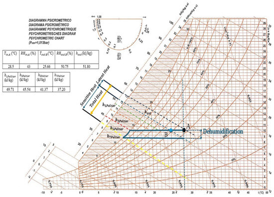
Figure 7.
Psychometric chart of the process considering January.
In general, dynamic simulations were performed throughout the year in order to obtain the values of condensed water flow rate. In fact, the trend is shown in Figure 8. The analysis indicates a fluctuating condensation trend with one, three, and five Peltier cells, alternating between no condensation and gradual increases, reaching up to 168.25 g/h with one cell. With seven Peltier cells, condensation increases significantly, peaking at 632.05 g/h in May at 3343 h.
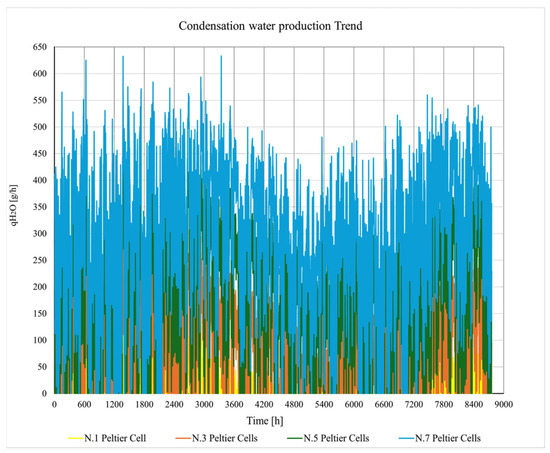
Figure 8.
Condensation water production trend.
Similarly, the temperature variations at the outlet of the Peltier cell section were systematically analysed, the results of which are illustrated in Figure 9. With one Peltier cell, the outlet air temperatures vary from approximately 293.08 K to 280.47 K (considering the extreme values), reflecting a modest cooling effect. As the number of active Peltier cells increases, the system demonstrates a progressively greater cooling capacity, with outlet temperatures decreasing accordingly.
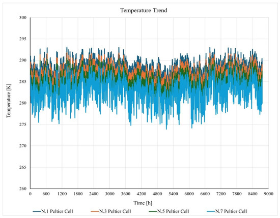
Figure 9.
Outlet temperature profile after the Peltier cell section.
In intermediate configurations, such as the one utilising five Peltier cells, the cumulative cooling power becomes sufficient to reach minimum temperatures of 276.23 K, indicating a significant removal of thermal load from the airflow. With seven Peltier cells, the outlet temperature approaches zero Kelvin, specifically reaching 273.89 K, effectively avoiding the presence of ice that could compromise the structural integrity of the system presented. In any case, it is worth emphasising that this progressive thermal behaviour confirms the direct correlation between the number of Peltier cells installed and the extent of temperature reduction achieved in the system.
3.3. Optimisation of Results: Regulation Technique
To improve efficiency and the quality of the results obtained, a rotary disc valve is strategically employed to regulate and reduce the incoming airflow. This adjustment leads to a substantial decrease in flow rate, specifically halving it to approximately 71.1 kg/h on the cold side of the cell. As illustrated in Figure 10, this controlled reduction in airflow initiates a more pronounced condensation phenomenon starting from the first configuration, where condensation is observed almost throughout the year, with a peak of 124.24 g/h during the month of February (1375 h). This value progressively increases in the subsequent configurations, ensuring better and more frequent condensate collection, even in setups involving a higher number of Peltier cells. Therefore, by using this regulation technique, it is not possible to guarantee the presence of condensation during all hourly intervals throughout the year in the four proposed configurations. However, the periods without condensation are significantly reduced. This makes it possible to operate with a lower number of Peltier cells while still achieving substantial values, without necessarily having to use seven Peltier cells (final configuration) as in the previous case.
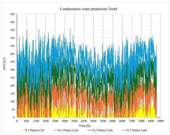
Figure 10.
Trend of collected condensate in Regulation Mode.
Comparison of Figure 9 and Figure 11 shows that as the flow rate is halved, there is a decrease in the outlet temperature.
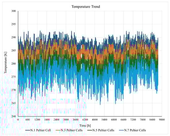
Figure 11.
Outlet temperature profile after the Peltier cell section in Regulation Mode.
With only one Peltier cell, the minimum outlet temperature recorded is approximately 279.46 K. This temperature continues to decrease as the number of active cells increases: it drops to 264.42 K when all seven Peltier cells are active.
Under these conditions, to ensure the integrity of the device, it is possible to provide for the use of a thermostatic control device that, once the desired temperature is reached, stops the air supply into the pipe.
4. Conclusions
This study investigated the thermal and fluid dynamic behaviour of a Horizontal Air–Ground Heat Exchanger (HAGHE), with a focus on how environmental variables such as temperature and humidity affect the heat exchange process and the occurrence of condensation. The system integrates Peltier cells to enhance the cooling effect, and its performance was evaluated under different boundary conditions through a combination of analytical modelling and numerical simulations.
The results showed that the thermal behaviour of the soil significantly influences the heat exchange rate and that the presence of moist air can trigger condensation within the ducts, contributing to an additional latent heat sink. The simulations confirmed that coupling thermoelectric modules with the geothermal probes leads to a measurable increase in cooling efficiency.
Moreover, the analysis highlighted the potential of using recycled Peltier cells as a low-cost solution to improve air treatment in warm and humid climates. The system’s passive nature, minimal maintenance requirements, and compatibility with renewable energy sources such as shallow geothermal energy make it a viable alternative or complement to conventional HVAC systems, particularly in contexts where energy efficiency and sustainability are priorities.
In summary, the proposed HAGHE system demonstrates the feasibility of integrating thermoelectric cooling with ground heat exchange to enhance the pre-conditioning of ventilation air. Its adaptability, modularity, and environmental compatibility offer promising perspectives for further development and practical applications in energy-efficient building systems.
Author Contributions
Conceptualization, C.B., M.S. and P.M.C.; methodology, C.B., P.M.C. and M.S.; software, P.M.C. and M.S.; validation, C.B., P.M.C. and M.S.; formal analysis, C.B., P.M.C., M.S., G.F.F., A.B. and M.B.; investigation, C.B., P.M.C., M.S., G.F.F., A.B. and M.B.; resources, C.B., P.M.C. and M.B.; data curation, C.B., P.M.C., M.S., G.F.F., A.B. and M.B.; writing—original draft preparation, C.B., P.M.C. and M.S.; writing—review and editing, C.B., P.M.C. and M.S.; visualization, C.B., P.M.C. and M.S.; supervision, C.B., P.M.C. and M.B.; project administration, C.B. and M.B.; funding acquisition, C.B. and M.B. All authors have read and agreed to the published version of the manuscript.
Funding
This study is funded by the “European Commission—Next Generation EU”—PNRR M4—C2–investimento 1.1: Fondo per il Programma Nazionale di Ricerca e Progetti di Rilevante Interesse Nazionale (PRIN)—PRIN 2022PNRR cod. F53D2300971 0001 “AIRcon.WATER (Air conditioning and Water from Air, by Thermal Earth Recovery)”, Università del SALENTO CUP F53D23009710001, Università degli Studi di PALERMO CUP B53D23027020001.
Data Availability Statement
The original contributions presented in this study are included in the article. Further inquiries can be directed to the corresponding author.
Conflicts of Interest
The authors declare no conflicts of interest.
Abbreviations
| Specific heat of soil [J·kg−1·K−1] | |
| Mass flow rate of water [g·h−1] | |
| Annual average value of the air temperature [K] | |
| Annual temperature range/2 [K] | |
| Days with the lowest temperature [K] | |
| Hours of the year [h] | |
| Burial depth [m] | |
| Max temperature difference at , and Q = 0 W [°C] | |
| Max current at [A] | |
| Max voltage at [V] | |
| Max cooling capacity at , and T = 0 °C [W] | |
| Greek letters | |
| Thermal diffusivity of soil [m2·s−1] | |
| Thermal conductivity of soil [W·m−1·K−1] | |
| Density of soil [kg·m−3] | |
| Period of the sinusoid [day] | |
| Acronyms | |
| EAHX | Earth-to-Air Heat Exchanger system |
| HAGHE | Horizontal Air–Ground Heat Exchanger system |
References
- Kumar, A.; Alam, T. A review on geothermal energy systems and various approaches to enhance the system’s performance. Energy Build. 2025, 344, 115962. [Google Scholar] [CrossRef]
- Nkinyam, C.M.; Ujah, C.O.; Asadu, C.O.; Kallon, D.V. Exploring Geothermal Energy as a Sustainable Source of Energy: A systemic Review. Unconv. Resour. 2025, 6, 100149. [Google Scholar] [CrossRef]
- Maghrabie, H.M.; Abdeltwab, M.M.; Tawfik, M.H.M. Ground-source heat pumps (GSHPs): Materials, models, applications, and sustainability. Energy Build. 2023, 299, 113560. [Google Scholar] [CrossRef]
- Ben, H.; Brown, C.S.; Kolo, I.; Falcone, G.; Walker, S. Decarbonising well-insulated buildings in a warming climate: The case of adaptive thermal comfort with geothermal space heating. Energy Build. 2024, 319, 114466. [Google Scholar] [CrossRef]
- Violante, A.C.; Donato, F.; Guidi, G.; Proposito, M. Comparative life cycle assessment of the ground source heat pump vs air source heat pump. Renew. Energy 2022, 188, 1029–1037. [Google Scholar] [CrossRef]
- Bina, S.M.; Fujii, H.; Qaisova, D.; Lein, R.; Rahmatov, J.; Inagaki, F. Ground source heat pump systems in Central Asia: A case study from Dushanbe, Tajikistan. Geothermics 2025, 128, 10328. [Google Scholar] [CrossRef]
- Li, W.; Li, X.; Wang, Y.; Tu, J. An integrated predictive model of the long-term performance of ground source heat pump (GSHP) systems. Energy Build. 2018, 159, 309–318. [Google Scholar] [CrossRef]
- Zhou, S.; Jia, H.; Zhou, B.; Liu, J.; Cui, P.; Yu, M. Study on the ground temperature response induced by GSHP system operation under different geological conditions. Geothermics 2025, 130, 103333. [Google Scholar] [CrossRef]
- Bhutta, M.M.A.; Hayat, N.; Bashir, M.H.; Khan, A.R.; Ahmad, K.N.; Khan, S. CFD applications in various heat exchangers design: A review. Appl. Therm. Eng. 2012, 32, 1–12. [Google Scholar] [CrossRef]
- Congedo, P.M.; Lorusso, C.; Baglivo, C.; Milanese, M.; Raimondo, L. Experimental validation of horizontal air-ground heat exchangers (HAGHE) for ventilation systems. Geothermics 2019, 80, 78–85. [Google Scholar] [CrossRef]
- Bordignon, S.; Carnieletto, L.; Zarrella, A. An all-in-one machine coupled with a horizontal ground heat exchanger for the air conditioning of a residential building. Build. Environ. 2022, 207, 108558. [Google Scholar] [CrossRef]
- Tong, C.; Li, X.; Ju, H.; Duanmu, L.; Huang, C. A hybrid numerical model for horizontal ground heat exchanger. Renew. Energy 2024, 230, 120825. [Google Scholar] [CrossRef]
- Lamarche, L.; Beauchamp, B. A new contribution to the finite line-source model for geothermal boreholes. Energy Build. 2007, 39, 188–198. [Google Scholar] [CrossRef]
- Priarone, A.; Fossa, M. Modeling the ground volume for numerically generating single borehole heat exchanger response factors according to the cylindrical source approach. Geothermics 2015, 58, 32–38. [Google Scholar] [CrossRef]
- Buscemi, A.; Beccali, M.; Guarino, S.; Brano, V.L. Coupling a road solar thermal collector and borehole thermal energy storage for building heating: First experimental and numerical results. Energy Convers. Manag. 2023, 291, 117279. [Google Scholar] [CrossRef]
- Misra, R.; Bansal, V.; Agrawal, G.D.; Mathur, J.; Aseri, T. Transient analysis based determination of derating factor for Earth Air Tunnel Heat Exchanger in winter. Energy Build. 2013, 58, 76–85. [Google Scholar] [CrossRef]
- Misra, R.; Bansal, V.; Agrawal, G.D.; Mathur, J.; Aseri, T. Transient analysis based determination of derating factor for earth air tunnel heat exchanger in summer. Energy Build. 2013, 58, 103–110. [Google Scholar] [CrossRef]
- Chiesa, G. EAHX–Earth-to-air heat exchanger: Simplified method and KPI for early building design phases. Build. Environ. 2018, 144, 142–158. [Google Scholar] [CrossRef]
- Li, J.; Jimenez-Bescos, C.; Calautit, J.K.; Yao, J. Evaluating the energy-saving potential of earth-air heat exchanger (EAHX) for Passivhaus standard buildings in different climates in China. Energy Build. 2023, 288, 113005. [Google Scholar] [CrossRef]
- Ougazzou, M.; El Maakoul, A.; Khay, I.; Degiovanni, A.; Bakhouya, M. Techno-economic and environmental analysis of a ground source heat pump for heating and cooling in Moroccan climate regions. Energy Convers. Manag. 2024, 304, 118250. [Google Scholar] [CrossRef]
- Saleem, A.; Ambreen, T.; Ugalde-Loo, C.E. Energy storage-integrated ground-source heat pumps for heating and cooling applications: A systematic review. J. Energy Storage 2024, 102, 114097. [Google Scholar] [CrossRef]
- Wakil, M.; Sghiouri, H.; Mghazli, M.O.; El Mghari, H.; Bakhouya, M.; Kaitouni, S.I. Integrating EAHX and ventilation systems through a decision-making algorithm for enhanced energy efficiency and thermal comfort in smart buildings. Energy Convers. Manag. 2025, 325, 119411. [Google Scholar] [CrossRef]
- Ghosal, M.K.; Tiwari, G.N. Modeling and parametric studies for thermal performance of an earth to air heat exchanger integrated with a greenhouse. Energy Convers. Manag. 2006, 47, 1779–1798. [Google Scholar] [CrossRef]
- Mannella, G.A.; La Carrubba, V.; Brucato, V. Peltier cells as temperature control elements: Experimental characterization and modeling. Appl. Therm. Eng. 2014, 63, 234–245. [Google Scholar] [CrossRef]
- Casano, G.; Piva, S. Experimental investigation of the performance of a thermoelectric generator based on Peltier cells. Exp. Therm. Fluid Sci. 2011, 35, 660–669. [Google Scholar] [CrossRef]
- Shi, L.; Abed, A.M.; Fayed, M.; Abdulghani, Z.R.; Anqi, A.E.; Khadimallah, M.A.; Moria, H.; Wae-Hayee, M. Economic cost analysis of air-cooling process using different numbers of Peltier modules; Experimental case study. Case Stud. Therm. Eng. 2023, 41, 102627. [Google Scholar] [CrossRef]
- Freire, L.O.; Navarrete, L.M.; Corrales, B.P.; Castillo, J.N. Efficiency in thermoelectric generators based on Peltier cells. Energy Rep. 2021, 7, 355–361. [Google Scholar] [CrossRef]
- Dipova, N. Design and development of peltier assisted infrared drying based soil moisture content device. KSCE J. Civ. Eng. 2019, 23, 29–36. [Google Scholar] [CrossRef]
- Congedo, P.M.; Baglivo, C.; Negro, G. A New Device Hypothesis for Water Extraction from Air and Basic Air Condition System in 487 Developing Countries. Energies 2021, 14, 4507. [Google Scholar] [CrossRef]
- Baglivo, C.; Buscemi, A.; Spagnolo, M.; Bonomolo, M.; Lo Brano, V.; Congedo, P.M. Toward a Sustainable Indoor Environment: Coupling Geothermal Cooling with Water Recovery Through EAHX Systems. Energies 2025, 18, 2297. [Google Scholar] [CrossRef]
- Meteonorm; Handbook part I: Software; Meteotest: Bern, Switzerland, 2020.
- Remund, J.S.C.M.; Müller, S.C.; Schilter, C.; Rihm, B. The use of Meteonorm weather generator for climate change studies. In Proceedings of the 10th European Conference on Applications of Meteorology (ECAM), Zürich, Switzerland, 13–17 September 2010. [Google Scholar]
- Meteonorm. Global Meteorological Database; Meteotest: Bern, Switzerland, 2012; Available online: https://meteonorm.com/en/ (accessed on 26 June 2025).
- Congedo, P.M.; Lorusso, C.; De Giorgi, M.G.; Laforgia, D. Computational fluid dynamic modeling of horizontal air-ground heat exchangers (HAGHE) for HVAC systems. Energies 2014, 7, 8465–8482. [Google Scholar] [CrossRef]
Disclaimer/Publisher’s Note: The statements, opinions and data contained in all publications are solely those of the individual author(s) and contributor(s) and not of MDPI and/or the editor(s). MDPI and/or the editor(s) disclaim responsibility for any injury to people or property resulting from any ideas, methods, instructions or products referred to in the content. |
© 2025 by the authors. Licensee MDPI, Basel, Switzerland. This article is an open access article distributed under the terms and conditions of the Creative Commons Attribution (CC BY) license (https://creativecommons.org/licenses/by/4.0/).