Abstract
This paper proposes a novel control strategy for a dual-stage grid-connected solar photovoltaic (PV) system designed to ensure reliable and efficient operation under unstable grid conditions. The strategy incorporates a Phase-Locked Loop (PLL)-based positive sequence estimator for accurate detection of grid voltage disturbances, including sags, swells, and fluctuations in solar irradiance. A dynamic DC-link voltage regulation mechanism is employed to minimize converter power losses and enhance the performance of the Voltage Source Converter (VSC) under weak grid scenarios. The control scheme maintains continuous maximum power point tracking (MPPT) and unity power factor (UPF) operation, thereby improving overall grid power quality. The proposed method is validated through comprehensive simulations and real-time hardware implementation using the OPAL-RT OP4510 platform. The results demonstrate compliance with IEEE Standard 519, confirming the effectiveness and robustness of the proposed strategy.
1. Introduction
Renewable Energy Sources (RES), including solar, wind, and hydro, are vital for achieving a sustainable and low-carbon energy future. Among these, solar energy is particularly promising due to its abundance, scalability, and ability to convert sunlight into electricity or heat using photovoltaic (PV) or solar thermal technologies [1]. Technological advancements have significantly enhanced the efficiency and cost-effectiveness of solar systems, positioning them as a key solution for reducing greenhouse gas emissions and dependence on fossil fuels. However, the conversion of DC power from solar PV systems into AC for grid integration introduces PQ issues, such as harmonics, voltage fluctuations, and waveform distortions primarily caused by inverter switching operations. Effective filtering and advanced inverter control strategies are essential to mitigate these issues. Moreover, the growing integration of RES and power-electronic-based loads continues to pose significant PQ challenges in modern electrical networks [2,3]. Major power quality (PQ) challenges in modern power systems include:
- Harmonic Distortions: The proliferation of non-linear loads, such as power electronic converters and energy-efficient appliances, introduces significant harmonic content, leading to increased system losses, equipment overheating, and malfunction of protection devices [4,5].
- Voltage Variations: Voltage sags, swells, and momentary interruptions degrade voltage stability, potentially disrupting the operation of sensitive loads and reducing system efficiency [6,7].
- Transient Disturbances: Fast, short-duration events caused by switching operations or fault conditions can result in insulation breakdown and damage to sensitive electronic components [4,8].
- Renewable Energy Integration: The variability and intermittency of sources like solar and wind exacerbate PQ issues such as voltage fluctuations and harmonic generation, particularly when not adequately controlled [9,10].
Voltage Source Converters (VSCs) are widely employed in solar PV systems to address power quality (PQ) challenges associated with DC–AC conversion. Utilizing advanced pulse-width modulation (PWM) techniques, VSCs generate high-quality sinusoidal AC waveforms, effectively mitigating harmonic distortions. Jain and Singh [11] developed a positive sequence estimator-based control strategy to improve power quality in a grid-connected, double-stage solar PV system. In addition to regulating output voltage, VSCs enhance system stability under varying load and input conditions and suppress transient disturbances through high-speed switching operations [12,13,14].
When integrated with MPPT algorithms, VSCs significantly improve overall system efficiency. MPPT ensures operation of the PV array at its optimal power point under changing irradiance and temperature conditions, while the VSC converts the optimized DC output into grid-compliant AC power. With advanced control strategies, VSCs enable precise regulation of voltage and current, minimize harmonic content, and ensure robust performance under dynamic operating scenarios [15,16].
System architectures that integrate MPPT, VSCs, and grid interfacing mechanisms are fundamental to the effective operation of modern photovoltaic (PV) systems. MPPT algorithms optimize energy extraction from the PV array, while VSCs ensure the delivery of high-quality AC power compatible with grid standards [17]. Mehta and Singh [18] investigated single-stage topologies, wherein a single VSC performs both MPPT and DC–AC conversion, offering a compact solution but necessitating sophisticated control strategies. Conversely, Mirhosseini et al. [19] proposed dual-stage configurations employing a dedicated DC–DC converter for MPPT and a separate VSC for grid interfacing, providing enhanced control flexibility at the expense of increased system complexity.
To enable the seamless integration of Distributed Energy Resources (DERs), it is imperative to address challenges such as power quality degradation, intermittency, and grid stability. Recent advancements—such as high-performance VSCs, adaptive MPPT algorithms, hybrid AC/DC architectures, and grid-forming inverter technologies—have demonstrated significant potential in overcoming these issues. These emerging solutions contribute not only to improved power quality and system resilience but also to enhanced adaptability under dynamic grid conditions, thereby supporting the global transition to sustainable and decentralized energy systems.
Voltage sags and swells in grid-connected systems adversely affect the performance of converters utilizing pulse-width modulation (PWM). These disturbances necessitate real-time adjustments in duty cycles and switching frequencies to maintain voltage stability, which can lead to increased switching losses and elevated current stress on power devices. Yan et al. [20] proposed a DSOGI-FLL-based control technique to mitigate PWM dead-time effects and eliminate current zero-crossing distortions. Additionally, the sensitivity of PWM to input voltage variations reduces conversion efficiency and contributes to thermal stress on the system components [21,22,23,24].
This paper presents an adaptive Positive Sequence Detection (PSD) control strategy for a grid-connected two-stage photovoltaic (PV) system aimed at enhancing power quality (PQ) under grid disturbances, including voltage sags, swells, unbalances, and waveform distortions. The proposed control framework integrates adaptive DC-link voltage regulation to ensure system stability and minimize losses in the VSC. A Perturb and Observe (P&O) algorithm is implemented for MPPT, enabling optimal energy extraction under varying solar irradiance conditions.
A prototype system was developed and evaluated under diverse operating scenarios, including fluctuating grid voltages and irradiance levels. Simulation and real-time experimental results obtained and compared with IEEE Standard 519 [25,26]. The key contributions of this work are:
- VSC-Based DC–AC Conversion: Enables efficient conversion of PV-generated DC power into grid-compliant AC for injection during available irradiance conditions;
- Active Harmonic Filtering: The VSC functions as an active filter, mitigating grid voltage distortions, compensating reactive power, and regulating the DC-link voltage to improve efficiency;
- Adaptive PSD Control: Accurately extracts positive sequence components (PSCs) from distorted grid voltages, ensuring balanced grid currents and maintaining Total Harmonic Distortion (THD) within IEEE 519 limits;
- Robust MPPT under Variable Irradiance: The P&O-based MPPT technique ensures consistent maximum power extraction under dynamic environmental conditions;
- Experimental Validation: The proposed system is validated through MATLABR2019b/Simulink simulations and real-time hardware-in-the-loop testing using the OPAL-RT OP4510 platform, confirming its practical viability and performance.
Paper Organization: Section 2 presents the mathematical modeling of the solar PV module. Section 3 discusses the overall system architecture and the PLL-based control strategy. Section 4 analyzes the system’s dynamic behavior through MATLAB simulation results. Section 5 presents experimental validation using the OP4510 hardware-in-the-loop simulator. Section 6 offers a comparative performance analysis with existing techniques. Section 7 concludes the paper, highlighting key contributions and future research directions.
2. Mathematical Framework for Solar PV Module
In practical applications, PV cells act as the essential building blocks for harnessing solar energy and converting it into electricity. Since a single PV cell generates only a small amount of power, multiple cells are combined to form PV modules, which enhance efficiency and output. To further scale up electricity generation, these modules are interconnected in specific series and parallel configurations, creating PV arrays. These arrays are the backbone of solar power systems, ensuring reliable and sustainable energy production. Each individual solar cell can be modeled as an electrical circuit component, demonstrating its role in the systematic conversion of sunlight into clean energy. This structured integration of PV cells, modules, and arrays is to optimizing solar energy utilization for various applications [27,28].
The solar PV device can be modeled as an ideal solar cell, represented by a current source () connected in parallel with a diode, as depicted in Figure 1. This equivalent circuit helps in understanding the electrical behavior of a solar cell by illustrating how the photocurrent generated by sunlight interacts with the intrinsic semiconductor properties of the device.
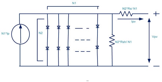
Figure 1.
Equivalent Electrical Representation of a PV Panel.
The current of the solar module, driven by the photocurrent, can be expressed using the following Equation (2)
where
—Solar module current.
—PV cell-generated current.
—Short circuit current.
—Diodereverses saturation current.
—Short circuit current coefficient at (25 °C).
—Reference temperature at 25 °C.
—Operating temperature of the device.
—Solar irradiance.
—Output voltage of PV array.
—Thermal voltage ()
—Number of solar modules connected in parallel.
—Number of PV cells connected in series.
and —Series and shunt resistance.
—Charge of electron.
—Diode ideality factor.
3. System Layout and Control Process
The proposed dual-stage solar PV system as shown in Figure 2, connected to a three-phase grid, introduces an innovative control strategy aimed at enhancing power quality under weak grid conditions. Unlike traditional approaches, this system integrates an APSE with dynamic control features, ensuring superior performance during voltage disturbances.
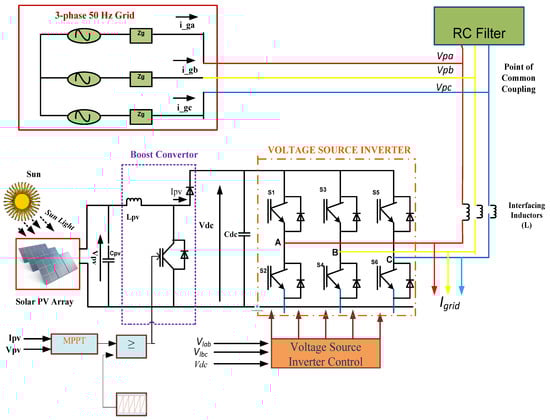
Figure 2.
Dual-stage solar PV system connected to a 3-phase grid.
3.1. System Architecture and Novel Features
The system (in Figure 2) consists of a solar PV array, DC-link capacitor, ripple filter, three-phase grid, AC inductors, VSC, and a DC–DC boost converter. A novel aspect of dual-stage PV inverter system that distinguish it from conventional designs following approach:
- Adaptive Control Mechanism: Unlike static control methods, our adaptive mechanism dynamically adjusts the DC-link voltage in real-time based on grid conditions, minimizing VSC losses during fluctuations;
- Enhanced PSE: We incorporate an improved PLL-based estimator that effectively isolates PSCs even under severe voltage sags, swells, and unbalanced grid conditions;
- Integrated Harmonic Mitigation: The VSC not only manages DC–AC conversion but also acts as an active filter, significantly reducing THD to below 3.90%, outperforming conventional SOGI-based methods.
3.2. Advanced Control Strategy
- A.
- MPPT Enhancement
The system utilizes an optimized P&O technique with adaptive gain tuning, which ensures rapid convergence to the maximum power point despite of sudden changes in solar irradiance. The duty cycle () for the boost converter is calculated as:
By integrating an adaptive gain control function, the system prevents local oscillations around the maximum power point, thus mitigating the common drawbacks of conventional MPPT algorithms.
- B.
- Dynamic VSC control
- a.
- Positive Sequence Component Isolation:
The PCC line voltages () are measured and transformed into their corresponding phase voltages (). This transformation is crucial for accurate monitoring and control of the system, ensuring proper phase balancing and optimal power distribution. By converting line voltages into phase voltages, the system can effectively manage and adjust power flow based on real-time operational conditions [29].
To further process these voltages, Clarke’s transformation is applied to convert the phase voltages into components, as represented in Figure 3:
where

Figure 3.
Block diagram of a control system for an integrator-based positive sequence filter.
To mitigate harmonic distortions, these transformed voltages are fed into a PSE utilizing an integrator-based control approach. This control strategy effectively extracts the PSC from unbalanced and distorted voltages, ensuring stable operation even under challenging grid conditions such as DC offset, voltage sag, swells, and waveform distortions. The estimator ensures system stability by dynamically adjusting for these grid disturbances. The value of as provided in Figure 3 is calculated which are given below,
—are provided in [Appendix A.1].
The inverse Clarke transformation, as formulated in (6), reconstructs the R–Y–B phase voltages from PSCs. These transformed voltages serve as inputs for the computation of the terminal PCC voltage () which is mathematically defined in (7), ensuring system stability and phase consistency.
- b.
- Control Strategy for PCC Voltage Regulation:
Figure 4 illustrates the control strategy implemented for maintaining PCC voltage stability, DC-link regulation, and grid synchronization in a three-phase grid-connected PV system. The control structure consists of multiple stages, including DC-link voltage control, reference current generation, and inverter switching using a hysteresis controller. The whole process can be explained in the following steps.
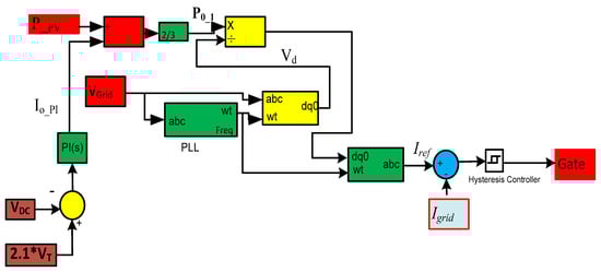
Figure 4.
Control strategy by using PLL.
- DC-Link Voltage Regulation Using PI Controller:
- The DC-link voltage regulation is a crucial aspect of the control system, ensuring that power transfer remains stable and efficient.;
- The reference DC-link voltage is compared with the measure DC link-voltage () to compute an error signal;
- This error is processed using a Proportional-Integral (PI) controller, which generates an output signal to compensate for losses and maintain the desired DC link voltage;
- The computed power loss component is integrated into the overall control scheme, influencing the reference grid current calculation as provided in (8).
- ii.
- Dynamic Reference Grid Current Computation:
- The reference grid currents are computed to ensure proper synchronization with the grid;
- The power generated by the PV array is dynamically adjusted by subtracting the loss component , giving the effective power component (
—is the power generated by PV array.
- c.
- PLL and Grid Reference Current Generation
To maintain proper synchronization between the PV output current and the grid voltage, a PLL-based control strategy is employed [28]. The PLL extracts the phase angle of the grid voltage, ensuring that the inverter-generated currents remain perfectly in phase with the grid. This synchronization is essential for stable power injection and maintaining a high-power factor (PF). The control scheme begins by transforming the three-phase grid voltages into reference frame using transformation. This transformation isolates the direct-axis voltage components, with the PLL ensuring that for accurate phase tracking.
- d.
- Grid Reference Current Computation
- Once the phase information is obtained, the reference grid current is computed to maintain balance power injection:
- 1.
- Extracting the active power component ( ) from the PV system;
- 2.
- Utilizing the direct-axis voltage , obtained from the transformed grid voltage, to determine the reference current;
- 3.
- Computing the required reference using:
Further, the calculated reference current is converted back into the frame using an inverse transformation. The final reference currents are then compared with actual grid currents, and the error is processed through a hysteresis controller, which generates the switching pulses for the VSC.
4. Simulation Results and Discussion
The system dynamically adapts to variations in irradiance and grid voltage, ensuring efficient PV operation and maintaining grid stability. This adaptive control maximizes power extraction, mitigates disturbances, and facilitates the reliable integration of renewable energy into the grid. The MATLAB/Simulink simulation parameters are listed in Appendix A.2.
- A.
- Performance during fluctuations in PV irradiation levels
Figure 5 shows the grid voltage, grid current, VSC current, DC-link voltage, and PV power. As insolation decreases, both the PV arrays current and the grid current decline, reducing power injection into the grid. However, the P&O MPPT algorithm maintains operation at the maximum power point, ensuring efficient energy conversion and stable grid integration under varying insolation conditions.
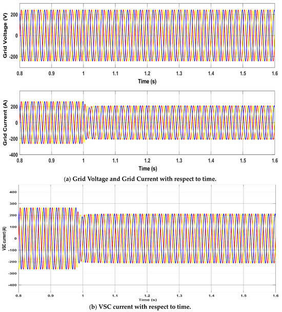
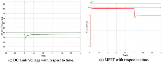
Figure 5.
Solar Irradiation Variation with respect to time.
- B.
- Performance during voltage sag
A sudden 20% grid voltage drop at t = 1 s, caused by load addition, is shown in Figure 6a, along with a corresponding reduction in grid current to maintain constant PV power output. To minimize converter losses, is adaptively regulated with grid voltage variations, as shown in Figure 6b. Similarly, Figure 6c illustrates that when the grid voltage decreases by 20%, the PV current increases to sustain power injection, while the DC-link voltage drops from 525 V to 420 V, further reducing converter losses. The injected power meets IEEE harmonic standards, with voltage and current THD of 3.90% and 1.28%, respectively. The current flowing in grid from solar panel increases, this increase ensures that the total power from the solar source remains constant shown in Figure 6d.
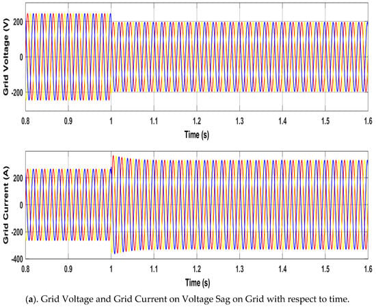
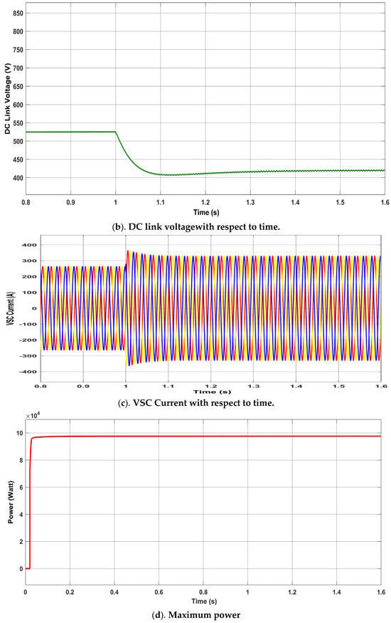
Figure 6.
Voltage Sag.
- C.
- Performance during voltage swell
A sudden 20% grid voltage rise, caused by load removal, is shown in Figure 7. At t = 1, the grid voltage increases by 20% (Figure 7a), while the grid current decreases to maintain constant PV power output. To minimize converter losses, VDC is adaptively adjusted with grid voltage variations, as illustrated in Figure 7b. The system is connected to a 100 kW PV array. During the grid voltage rise, the PV current decreases proportionally shown in Figure 7c, ensuring constant power injection, while the DC-link voltage increases from 525 V to 630 V, further reducing converter losses. The current flowing in grid from solar panel decreases, this decrease ensures that the total power from the solar source remains constant shown in Figure 7d. The harmonic content of the injected power remains within IEEE limits, with voltage and current THD measured at 3.90% and 1.28%, respectively, as shown in Figure 8.
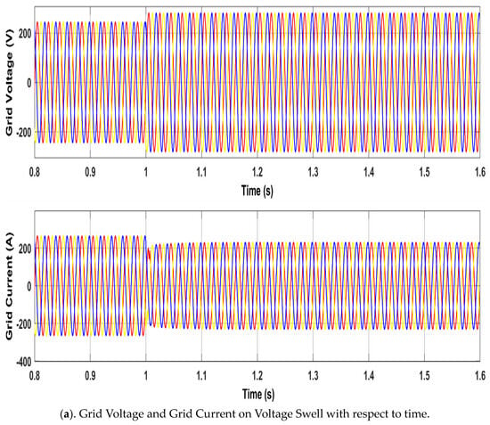
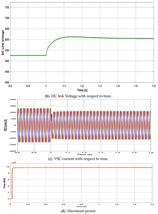
Figure 7.
Voltage Swell.
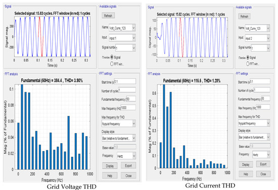
Figure 8.
Voltages and Current THD.
5. Experimental Result and Analysis [25]
The proposed approach was validated through real-time experiments on an OPAL-RT platform for a three-phase system. Figure 9A shows the OPAL-RT implementation block diagram, and Figure 9B depicts the experimental setup, which includes the OP4510 simulator (Xilinx Kintex-7 FPGA), host PC, I/O interface cards, communication interface, and LAN. The system was integrated using MATLAB/Simulink and RT-LAB (v2021.3.4), with data captured via a KEYSIGHT DSOX2024A oscilloscope. Voltage control of a weak grid using MPPT was tested under three scenarios over 0.8–1.6 s, matching the MATLAB simulation conditions. Parameters remained constant from 0.8 to 1.0 s, with scenario-specific variations applied after 1.0 s.
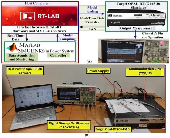
Figure 9.
(A) Block diagram of OPAL RT (OP4510). (B) Experimental setup.
- ➢
- Case-1: Variation in PV Irradiation t = 1 Second
At an irradiance of 1000 W/m2, the grid voltage and current are 245 V (per phase, peak) and 265 A (peak), respectively. When irradiance drops to 80% of its nominal value, the line current decreases to 210 A, while the grid voltage remains constant. Simulink simulation results are shown in Figure 5, and OPAL-RT experimental results are shown in Figure 10.
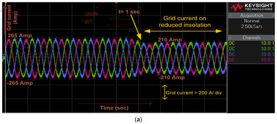
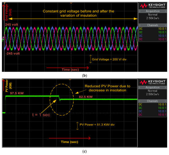
Figure 10.
(a) Grid Current, (b) Grid Voltage, (c) PV power, at variation in PV irradiation.
- ➢
- Case-2: Voltage Sag at t = 1 Second
In Case 2, a voltage sag is applied at t = 1 s. Before the sag, the grid voltage is 245 V per phase (peak, Figure 11a), line current is 265 A (peak, Figure 11b), DC-link voltage is 525 V (Figure 11c), and PV power output is 9.8 × 10⁴ W (Figure 11d). After the sag, the grid voltage drops to 0.8 × 245 V (Figure 11a), the line current rises to 360 A (peak, Figure 11b), the DC-link voltage decreases to 420 V (Figure 11c), while PV power remains constant (Figure 11d). OPAL-RT results closely align with Simulink simulations, with Figure 6a–d and Figure 11a–d showing consistent behavior, confirming the proposed model’s accuracy and robustness across platforms.
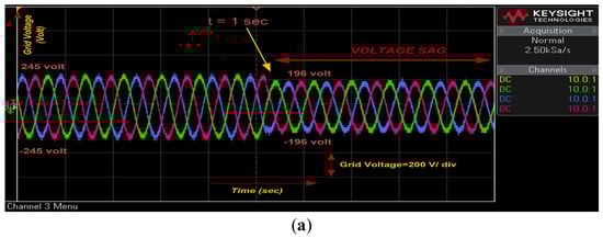
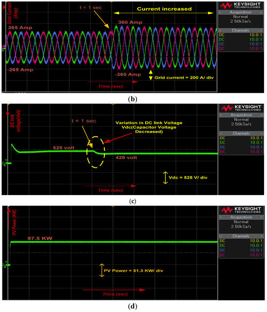
Figure 11.
(a) Grid voltage, (b) Grid current, (c) DC link voltage, (d) PV power, at voltage sag.
- ➢
- Case-3: Voltage Swell at t = 1 Second
In Case 3, a voltage swell is applied at t = 1 s. Before the swell, the grid voltage is 245 V per phase (peak, Figure 12a), line current is 265 A (peak, Figure 12b), DC-link voltage is 525 V (Figure 12c), and PV power output is 9.8 × 10⁴ W (Figure 12d). After the swell, the grid voltage increases to 1.2 × 245 V (Figure 12a), line current decreases to 220 A (peak, Figure 12b), and DC-link voltage rises to 630 V (Figure 12c), while PV power remains constant (Figure 12d). The OPAL-RT results align closely with the Simulink simulations, confirming the model’s accuracy and robustness across platforms, with Figure 7a–d and Figure 12a–d showing consistent behavior.
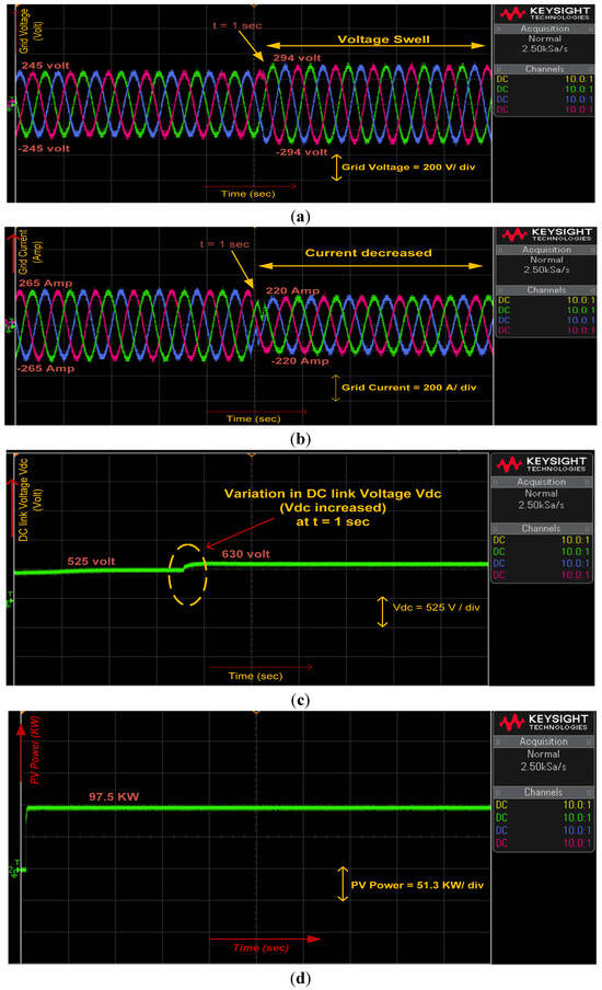
Figure 12.
(a) Grid voltage, (b) Grid current, (c) DC link voltage, (d) PV power, at voltage swell.
6. Comparison of Different Control Strategies
Table 1 summarizes the parameters used in the simulations and experiments to assess the performance of the proposed method alongside the SOGI-D, DSOGI, and SOGI-Q techniques.

Table 1.
Parameters of the test system.
Table 2 presents a comparison of the proposed technique with SOGI-D, DSOGI, and SOGI-Q in terms of dynamic recovery time, harmonic elimination, and DC offset rejection. During grid recovery from disturbances, the proposed method achieves lower DC offset, enhanced harmonic suppression, and shorter dynamic recovery time, resulting in a cleaner and faster power response. It outperforms SOGI-D, DSOGI, and SOGI-Q in both DC offset removal and harmonic elimination. Moreover, the proposed technique exhibits significantly reduced dynamic recovery time when reaching steady state under conditions of voltage sag, voltage swell, and irradiance variation. In addition, it consistently maintains unity power factor at the grid side while extracting maximum power from the solar panel. Table 3 gives a comparison of proposed technique with SOGI-Q and DSOGI based on statistical analysis of the data on the total harmonic distortion (THD) of the grid voltage under three operating scenarios: sag, swell and irradiation changes [30].
Table 2.
Comparison of proposed technique with SOGI-D, DSOGI and SOGI-Q techniques.
Table 3.
Comparison of proposed technique with DSOGI and SOGI-Q based on statistical inference of voltage harmonic for sag, swell and fluctuations in solar irradiance.
7. Conclusions
This paper presented a PLL-based positive sequence estimator for a dual-stage grid-connected solar PV system operating under abnormal grid conditions. The proposed control strategy ensures accurate detection of voltage disturbances and employs dynamic DC-link regulation to minimize VSC losses, particularly under weak grid scenarios. Simulation and real-time validation using MATLAB/Simulink and the OPAL-RT OP4510 platform confirm enhanced grid stability, improved power quality, and consistent MPPT with unity power factor operation. The system meets IEEE Standard 519 requirements, demonstrating its effectiveness and suitability for practical grid-connected PV applications. The proposed control framework can be extended in several directions. Future work may involve integrating hybrid renewable systems, such as PV–wind or PV–storage configurations, to enhance reliability and energy management. The adoption of grid-forming VSCs could further improve system stability in weak or inverter-dominated grids. Advancing MPPT algorithms using artificial intelligence or model predictive control can enhance tracking accuracy under rapidly varying irradiance and temperature conditions.
Author Contributions
Conceptualization, L.S.T.; Methodology, P.K.S.; Software, P.K.S.; Formal analysis, P.K.S. and P.S.; Investigation, P.S., S.C.C. and L.S.T.; Resources, S.C.C. and L.S.T.; Writing—review & editing, P.S.; Supervision, P.S., S.C.C. and L.S.T.; Funding acquisition, P.K.S. All authors have read and agreed to the published version of the manuscript.
Funding
This research received no external funding.
Data Availability Statement
The original contributions presented in this study are included in the article. Further inquiries can be directed to the corresponding author.
Conflicts of Interest
The author(s) declared no potential conflicts of interest with respect to the research, authorship, and/or publication of this article.
Nomenclature
| PV | Photovoltaic |
| VSC | Voltage Source Converter |
| RES | Renewable Energy Sources |
| DER | Distributed Energy Resources |
| PQ | Power Quality |
| PCC | Point of Common Coupling |
| PLL | Phase Locked Loop |
| PSE | Positive Sequence Estimator |
| APSE | Adaptive Positive Sequence Estimator |
| PSD | Positive Sequence Detection |
| MPPT | Maximum Power Point Tracking |
| SOGI | Second Order Generalized Integrators |
| UPF | Unity Power Factor |
| PSC | Positive Sequence Components |
| P&O | Perturb and observe |
| DVR | Dynamic Voltage Restorer |
| THD | Total Harmonic Distortion |
| Inductor of boost converter | |
| Capacitor of boost converter | |
| DC link capacitor | |
| Grid impedance | |
| to | MOSFET of VSC |
| and | Line current of grid for , and phase |
| PCC line voltage between phase and phase | |
| PCC phase voltage of , and phase | |
| Terminal PCC voltage | |
| DC link voltage | |
| component of Clark transformation of PCC phase voltage | |
| component of input voltage of inverse Clark transform (output of filter). | |
| Filtered output voltage of inverse Clark transform | |
| and | loop gain of filter |
| Output power of solar panel | |
| Grid line voltage | |
| Grid line current | |
| Direct axis voltage component of to transformation |
Appendix A
Appendix A.1
Appendix A.2
Simulation parameters:
.
References
- Juarez-Perez, E.J.; Momblona, C.; Casas, R.; Haro, M. Enhanced power-point tracking for high hysteresis perovskite solar cells with a galvanostatic approach. Cell Rep. Phys. Sci. 2024, 5, 101885. [Google Scholar] [CrossRef]
- Modi, G.; Singh, B. Power quality improvement in solar energy conversion system integrated to weak ac grid. J. Inst. Eng. Ser. B 2024, 105, 1511–1526. [Google Scholar] [CrossRef]
- Alturki, Y.A.; Alhussainy, A.A.; Alghamdi, S.M.; Rawa, M. A novel point of common coupling direct power control method for grid integration of renewable energy sources: Performance evaluation among power quality phenomena. Energies 2024, 17, 5111. [Google Scholar] [CrossRef]
- Saxena, V.; Kumar, N.; Singh, B.; Panigrahi, B.K. A voltage support control strategy for grid integrated solar PV system during abnormal grid conditions utilizing interweaved GI. IEEE Trans. Ind. Electron. 2020, 68, 8149–8157. [Google Scholar] [CrossRef]
- Nguyen, N.T.; Hosani, K.A.; Al-Sumaiti, A.S.; Nguyen, T.H.; Jaafari, K.A.A.; Alsawalhi, J.Y. Fast harmonic rejecting control design to enable active support of charging stations to micro-grids under distortion. IEEE Trans. Transp. Electrif. 2023, 9, 4132–4146. [Google Scholar] [CrossRef]
- Devassy, S.; Singh, B. Performance analysis of solar PV array and battery integrated unified power quality conditioner for microgrid systems. IEEE Trans. Ind. Electron. 2021, 68, 4027–4035. [Google Scholar] [CrossRef]
- Dahesh, M.; Al-Matwakel, M.; Dhamrin, M. Degradation analysis of 38-year-old PV modules under the weather conditions of sana’a-yemen. IEEE J. Photovolt. 2025, 15, 137–145. [Google Scholar] [CrossRef]
- Mishra, S.; Mallick, R.K.; Nayak, P.; Ramasamy, T.N.; Panda, G. Dynamic power quality disturbance classification in grid-integrated PV systems: Leveraging clark transformed modal voltage and subspace weighted KNN. IEEE Access 2024, 12, 116572–116586. [Google Scholar] [CrossRef]
- Wang, K.; Yuan, Z.; Song, Q.; Xin, Q.; Huang, B.; Liu, W.; Feng, J. Grid-forming offshore wind farm integration through LCC-assisted diode rectifier. IEEE Trans. Power Deliv. 2025, 40, 178–190. [Google Scholar] [CrossRef]
- Saroha, J.; Pandove, G.; Singh, M. Modelling and simulation of grid connected SPV system with active power filtering features. J. Inst. Eng. Ser. B 2018, 99, 25–35. [Google Scholar] [CrossRef]
- Jain, V.; Singh, B. Power quality improvement in PV system tied to weak grid. IEEE Trans. Ind. Appl. 2021, 57, 1265–1273. [Google Scholar] [CrossRef]
- Xiong, L.; Liu, X.; Liu, Y.; Zhuo, F. Modeling and stability issues of voltage-source converter-dominated power systems: A review. CSEE J. Power Energy Syst. 2022, 8, 1530–1549. [Google Scholar] [CrossRef]
- Taghvaie, A.; Warnakulasuriya, T.; Kumar, D.; Zare, F.; Sharma, R.; Vilathgamuwa, D.M. A comprehensive review of harmonic issues and estimation techniques in power system networks based on traditional and artificial intelligence/machine learning. IEEE Access 2023, 11, 31417–31442. [Google Scholar] [CrossRef]
- Srikanth, M.; Kumar, Y.V.P.; Amir, M.; Mishra, S.; Iqbal, A. Improvement of transient performance in microgrids: Comprehensive review on approaches and methods for converter control and route of grid stability. IEEE Open J. Ind. Electron. Soc. 2023, 4, 534–572. [Google Scholar] [CrossRef]
- Dileep, G.; Singh, S.N. Maximum power point tracking of solar photovoltaic system using modified perturbation and observation method. Renew. Sustain. Energy Rev. 2015, 50, 109–129. [Google Scholar] [CrossRef]
- Mohamed, F.; Wasti, S.; Afshar, S.; Macedo, P.; Disfani, V. Mmc-based distributed maximum power point tracking for photovoltaic systems. In Proceedings of the 2020 IEEE Power & Energy Society General Meeting (PESGM), Montreal, QC, Canada, 2–6 August 2020; pp. 1–5. [Google Scholar] [CrossRef]
- Jahid, M.; Ehtesham, S.; Kirmani, B.; Manullah. Application of flower pollination algorithm and its comparative analysis for MPPT of solar panels under partial shading conditions. J. Inst. Eng. Ser. B 2025. [Google Scholar] [CrossRef]
- Mehta, G.; Singh, S.P. Design of single-stage three-phase grid-connected photovoltaic system with MPPT and reactive power compensation control. Int. J. Power Energy Convers. 2014, 5, 211–227. [Google Scholar] [CrossRef]
- Mirhosseini, M.; Pou, J.; Agelidis, V.G. Single-and two-stage inverter-based grid-connected photovoltaic power plants with ride-through capability under grid faults. IEEE Trans. Sustain. Energy 2015, 6, 1150–1159. [Google Scholar] [CrossRef]
- Yan, Q.; Zhao, R.; Yuan, X.; Ma, W.; He, J. A DSOGI-FLL-based dead-time elimination PWM for three-phase power converters. IEEE Trans. Power Electron. 2018, 34, 2805–2818. [Google Scholar] [CrossRef]
- Jain, C.; Singh, B. A single-phase two-stage grid interfaced SPV system with adjustable DC link voltage for VSC under non ideal grid conditions. In Proceedings of the 2014 IEEE International Conference on Power Electronics, Drives and Energy Systems (PEDES), Mumbai, India, 16–19 December 2014; IEEE: Piscataway, NJ, USA, 2015; pp. 1–6. [Google Scholar] [CrossRef]
- Laasri, S.; Hafidi, E.M.E.; Mortadi, A.; Chahid, E.G. Solar-powered single-stage distillation and complex conductivity analysis for sustainable domestic wastewater treatment. Environ. Sci. Pollut. Res. 2024, 31, 29321–29333. [Google Scholar] [CrossRef]
- Hafidi, E.M.E.; Chahid, E.G.; Mortadi, A.; Laasri, S. Study on a new solar-powered desalination system to alleviate water scarcity using impedance spectroscopy. Mater. Proceeding 2024. [Google Scholar] [CrossRef]
- Menti, A.; Pachoos, P.; Psomopoulos, C.S. Supraharmonic Distortion at the grid connection point of a network comprising a photovoltaic system. Energies 2025, 18, 564. [Google Scholar] [CrossRef]
- IEEE P519.1/D12; IEEE Draft Guide for Applying Harmonic Limits on Power Systems. IEEE: Piscataway, NJ, USA, 2015; pp. 1–124. Available online: https://ieeexplore.ieee.org/servlet/opac?punumber=6246648 (accessed on 17 May 2025).
- IEEE Std. 1159-2019; IEEE Recommended Practice for Monitoring Electric Power Quality. IEEE: Piscataway, NJ, USA, 2019; pp. 1–98. Available online: https://ieeexplore.ieee.org/document/8796486 (accessed on 17 May 2025).
- Khan, M.T.; Singh, P.; Chauhan, A.; Arya, R.; Verma, A.; Titare, L.S.; Choube, S.C. Optimal placement of multiple distributed generators using a novel voltage stability indicator employing arithmetic optimization algorithm. Comput. Electr. Eng. 2023, 110, 108853. [Google Scholar] [CrossRef]
- Vinod; Kumar, R.; Singh, S.K. Solar photovoltaic modeling and simulation: As a renewable energy solution. Energy Rep. 2018, 4, 701–712. [Google Scholar] [CrossRef]
- Yang, Z.; Chen, Y.; Yang, S.; Mak, P.I.; Martins, R.P. A 10.6-mW 26.4-GHz dual-loop type-II phase-locked loop using dynamic frequency detector and phase detector. IEEE Access 2020, 8, 2222–2232. [Google Scholar] [CrossRef]
- Arya, L.D.; Singh, P.; Titare, L.S. Optimum load shedding based on sensitivity to enhance static voltage stability using DE. Swarm Evol. Comput. 2012, 6, 25–38. [Google Scholar] [CrossRef]
Disclaimer/Publisher’s Note: The statements, opinions and data contained in all publications are solely those of the individual author(s) and contributor(s) and not of MDPI and/or the editor(s). MDPI and/or the editor(s) disclaim responsibility for any injury to people or property resulting from any ideas, methods, instructions or products referred to in the content. |
© 2025 by the authors. Licensee MDPI, Basel, Switzerland. This article is an open access article distributed under the terms and conditions of the Creative Commons Attribution (CC BY) license (https://creativecommons.org/licenses/by/4.0/).